Abstract
Advancements in ship propulsion technologies are essential for improving the efficiency and reliability of maritime transportation. This study introduces a comprehensive approach that integrates motor design with sensorless control strategies, specifically focusing on Dual Three-Phase Permanent Magnet Vernier Motors (DTP-PMVM) for ship propulsion. The initial section of the paper explores the design of a 5-MW DTP-PMVM using finite element method (FEM) analysis in dual three-phase configurations. The subsequent section presents a novel sensorless control technique employing a Prescribed-time Sliding Mode Observer (PTSMO) for accurate speed and position estimation of the DTP-PMSM, eliminating the need for physical sensors. The proposed observer convergence time is entirely independent of the initial estimation guess and observer gains, allowing for pre-adjustment of the estimation error settling time. Initially, the observer is designed for a DTP-PMVM with fully known model parameters. It is then adapted to accommodate variations and unknown parameters over time, achieving prescribed-time observation. This is accomplished by using an adaptive observer to estimate the unknown parameters of the DTP-PMVM model and a Neural Network (NN) to compensate for the nonlinear effects caused by the model’s unknown terms. The adaptation laws are innovatively modified to ensure the prescribed time convergence of the entire adaptive observer. MATLAB (R2023b) Simulink simulations demonstrate the superior speed-tracking accuracy and robustness of the speed and position observer against model parameter variations, strongly supporting the application of these strategies in real-world maritime propulsion systems. By integrating these advancements, this research not only proposes a more efficient, reliable, and robust propulsion motor design but also demonstrates an effective control strategy that significantly enhances overall system performance, particularly for maritime propulsion applications.
1. Introduction
In the ship propulsion industry, achieving a certain level of redundancy is crucial for improving safety, reliability, and operational availability [1,2,3]. Several methods are employed to enhance redundancy in electrical drives, including (a) adding a backup system, (b) designing fault-tolerant drives, and (c) converting a single-drive architecture into multiple independent units, such as dual or triple systems [4]. Among these, the dual three-phase system is particularly promising, as it requires only minor modifications to the stator winding, offering a simpler and more cost-effective solution. Due to the increased number of phases in DTP-PMSMs, several innovative methods for rotor position estimation have been developed, highlighting specific advantages of DTP-PMSMs in sensorless control applications [5]. This paper presents an integrated approach that combines the design of DTP-PMVM with sensorless control techniques, setting a new standard for propulsion technologies in the maritime industry.
The research begins with the meticulous design of a 5-MW DTP-PMVM, specifically tailored for ship propulsion applications, leveraging FEM analysis. Additionally, a new terminal sliding mode observer for sensorless control is introduced.
Recent research has also explored intelligent energy management strategies for hybrid and electric propulsion systems, particularly in connected vehicle environments, to improve overall system efficiency and control robustness [6]. Such studies complement the objectives of this work, which also aims to enhance propulsion control performance through advanced observer-based methods.
Using dual three-phase electrical machines offers several advantages, with redundancy being the most significant. These machines can continue operating even when one set of windings experiences an open or short circuit, making them highly desirable for fault-tolerant applications in safety-critical areas like ship propulsion or other transportation systems [7,8,9,10,11]. Moreover, dual three-phase configurations enhance the winding factor, which improves torque. They also reduce non-working harmonic components, resulting in lower core losses, improved efficiency, and minimized torque ripple [12,13,14]. Additionally, dual three-phase systems can reduce stator copper losses and thermal stress on power devices and motor windings due to lower current levels compared to conventional three-phase PM motors at the same power output [15].
Low gear ratio vernier machines are also considered promising candidates for direct-drive industrial applications, such as ship propulsion, due to their cost-effectiveness, fast dynamic response, high power density, and efficiency [16,17]. Additionally, the shape of the rotor permanent magnets (PMs) in low gear ratio configurations has a significant impact on performance. Research has shown that, in a comparison between interior PMVMs and surface-mounted PMVMs with low gear ratios, the surface-mounted configuration performs better and could be a strong candidate at the 5-MW level for this application. Therefore, the purpose of this research is to design a dual three-phase PMVM with a low gear ratio for the surface-mounted PM configuration.
Sensorless control techniques can be classified into two main categories. Model-based sensorless control methods are suitable for medium to high-speed operations, whereas saliency-based sensorless control methods are effective at low and zero speeds [5,18]. Techniques such as the Luenberger observer [19], sliding mode observer (SMO) [20,21], and model reference adaptive system (MRAS) [22] are commonly used to estimate rotor position in electric machines, providing precise rotor position and speed estimation at medium and high speeds. However, their accuracy and reliability decrease at low or zero speeds. At these lower speeds, the high-frequency (HF) injection algorithm is typically employed, leveraging the motor’s inherent saliency or saliency induced by inductance saturation effects [23]. Some research has investigated hybrid methods, combining HF signal injection at low speeds with SMO for medium and high-speed ranges [24]. With the increasing use of sensorless PMVM drives, developing effective observers is essential for ensuring robust control. Observer performance can vary significantly under different load conditions, and some methods, such as the extended Kalman filter (EKF), may not be suitable for ship propulsion due to their computational demands and lengthy execution times. Given the specific load characteristics in ship propulsion, designing an appropriate observer is crucial for reliable and robust system control in safety-critical applications [25,26].
The sliding mode observer (SMO) is particularly valued for its ability to enhance system robustness in PMVM drives. When a system operates within the sliding manifold, it follows the manifold dynamics, effectively compensating for parameter variations and external disturbances. However, traditional first-order sliding mode observers suffer from severe chattering. To overcome this limitation, numerous advanced SMO-based sensorless control strategies have been proposed in recent years: An adaptive second-order disturbance observer (SODO) that does not require prior knowledge of disturbance bounds has been developed for surface-mounted PMSMs [27,28,29]. This observer guarantees finite-time convergence of both disturbance and its derivative while automatically adjusting the switching gain to the minimum possible value, thereby significantly suppressing chattering and improving position estimation accuracy without a phase-locked loop.
A continuous variable boundary-layer sliding mode observer combined with position error feedforward compensation has been introduced for high-speed PMSMs operating up to 30,000 r/min [28]. By mitigating buffeting and compensating for delays and inverter nonlinearities, this method achieves remarkably high position estimation precision compared to conventional SMOs.
A decoupling sliding-mode observer tailored for bearingless permanent magnet vernier motors with special dual-purpose no-voltage windings has been presented [29]. The observer successfully decouples torque and suspension currents, enabling accurate back-EMF observation and rotor position estimation in highly integrated bearingless structures.
An improved adaptive super-twisting SMO together with an improved super-twisting quadrature signal generator (IST-QSG) has been proposed to eliminate low-pass filter phase delay and reduce chattering over a wide speed range [30]. Experimental results confirm superior speed and position estimation accuracy and robustness against disturbances.
An adaptive nonsingular fast terminal sliding mode observer (ANFTSMO) that adapts the switching gain according to the sliding surface has been designed to accelerate convergence and further suppress chattering [31]. Verified on a 1 kW PMSM platform, it exhibits higher position estimation accuracy and stronger robustness than conventional nonsingular terminal SMOs. A sliding mode predictive observer (SMPO) that completely eliminates the need for manual gain selection has been developed for variable-leakage-flux PMSMs [32]. By integrating an improved forgetting-factor recursive least-squares parameter identification, it simultaneously achieves fast response, minimal chattering, and effective compensation of parameter variations.
A hybrid terminal sliding-mode flux observer within an indirect field-oriented control framework has been introduced for fast bidirectional startup of PMSMs [33]. The observer removes the need for flux measurement or pure integration and demonstrates quick rotor synchronization without prior load torque knowledge. An improved SMO using a fuzzy logic controller to online tune the switching gains, combined with a dual second-order generalized integrator frequency-locked loop (DSOGI-FLL), has been proposed [34]. This structure effectively suppresses chattering and eliminates phase delay caused by traditional low-pass filters, outperforming super-twisting-based methods in dynamic performance.
An improved sliding mode speed controller with a time-varying reaching law, together with a sliding mode position observer based on the inductance model, has been presented for switched reluctance motors [35]. By introducing a time-varying function, the initial harmful peak at startup is greatly reduced while maintaining high estimation precision and robustness against load disturbances.
A new adaptive fast power reaching law SMO combined with an extended-state-observer-based higher-order PLL has been presented for low-chattering sensorless control [36]. The adaptive gains accelerate convergence when far from the sliding surface and automatically reduce chattering near the surface while using a sigmoid function as the switching element.
A gain-adaptive high-order terminal sliding mode observer (GA-HOTSMO) that dynamically adjusts the sliding-mode gain according to the system state has been developed [37]. The gain increases during large errors for fast convergence and decreases near the sliding surface to suppress chattering, yielding significantly lower current and back-EMF estimation errors than fixed-gain HOTSMOs.
A super-twisting algorithm-based SMO with a modified PLL has been applied to surface-mounted PMSMs to reduce chattering and phase delay [38]. The approach achieves excellent tracking of the d-axis back-EMF, thereby improving the transient performance of the sensorless FOC drive.
A global fast terminal sliding mode observer combined with a PLL has been proposed for in-wheel PMSMs in electric vehicles [39]. It ensures convergence from any initial condition with minimal chattering and provides rapid, overshoot-free speed tracking even under sensor failure scenarios.
An improved back-EMF observer combined with an extended state observer and adaptive mechanisms has been introduced to handle model uncertainties and disturbances [40]. The resulting sensorless control scheme exhibits smaller estimation errors, faster convergence, and stronger robustness with significantly reduced chattering.
In the domain of sliding mode observers (SMOs), several pioneering methodologies have emerged, notably including Finite-Time Sliding Mode Observers (FTSMOs), Fixed-Time Sliding Mode Observers (FxTSMOs), and Prescribed-Time Sliding Mode Observers (PTSMOs) [41]. The Finite-Time Sliding Mode Observer is characterized by its ability to ensure that the observation error converges to zero within a finite time frame. This means that the settling time of the estimation error is confined to a specific duration. However, it is important to note that this settling time is influenced by both the initial estimation error and the observer gains, leading to potential limitations in robustness [42]. Subsequently, the Fixed-Time Sliding Mode Observer was developed, offering a significant advancement. This method guarantees that the upper bound of the settling time is independent of the initial conditions of the estimation error. However, it remains dependent on observer gains. Notably, while it improves over the finite-time observer, the settling time is not entirely independent of the initial conditions. To address the limitations presented by both the Finite-Time and Fixed-Time SMOs, the Prescribed-Time Sliding Mode Observer was introduced. This innovative approach guarantees that the settling time is entirely independent of the initial conditions and observer gains, allowing for a pre-adjustable convergence time that enhances its precision and speed [43].
Building upon the preceding discussion, the development of a sensorless control strategy utilizing a prescribed-time speed and position observer is essential for the reliable and cost-effective control of the DTP-PMVM. This need is particularly pertinent given that the motor parameters may fluctuate across different speed ranges and operating conditions. Consequently, this paper aims to design a Prescribed-Time Sliding Mode Observer (PT-SMO) for the sensorless control of the DTP-PMVM, facilitating the estimation of both position and speed within a configurable time frame while ensuring high precision and rapid convergence. The observer design is conducted across two distinct scenarios. In the first scenario, we consider fixed parameters for the DTP-PMVM and proceed to design a PT-SMO, simulating its performance in Simulink. The results demonstrate the effectiveness of the proposed observer in accurately estimating position and speed. In the second scenario, based on Motor-CAD simulations, we observe that the DTP-PMVM parameters vary with different speeds. We gather these varying parameters into a lookup table and incorporate them into Simulink to model the DTP-PMVM with variable parameters. Results from simulations using the observer designed for fixed parameters reveal that the method does not perform adequately in estimating speed and position under these varying conditions. To address this challenge, we enhance our PT-SMO through an adaptive method that employs a Neural Network approximation. This approach allows for the estimation of unknown parameters within the DTP-PMVM model using adaptation laws, while the neural network effectively estimates the unknown nonlinear functions that arise in the process. The designs of the adaptive observer, the adaptation laws for the unknown modal parameters, and the neural network are employed to estimate and adapt the weights are structured to ensure the prescribed-time convergence of the entire observer. The simulation results indicate that the adaptive observer significantly outperforms the PT-SMO designed for fixed parameters.
Section 2 outlines the principles underlying the proposed design of the DTP-PMVM in Motor-CAD. Section 3 is dedicated to the mathematical modelling of the dynamics of the DTP-PMVM and VSD transformation, which facilitates the controller and observer design. Section 4 introduces the propeller load model. Section 5 delineates the sensorless control methodology and observer design. Section 6 presents the simulation results of the proposed sensorless control method applied to a 5 MW system. Finally, Section 7 offers conclusions and discusses future work.
2. Operation Principle and Proposed Design
Owing to the modulation effect, the PMVM operates inherently at low speeds while generating high torque [15]. The pole-slot combinations of a PMVM are governed by the following equations
where Q, , , and represent the number of stator slots, the number of rotor pole pairs, the number of stator winding pole pairs, and the gear ratio, respectively. Based on recent research, for MW-level applications, a low gear ratio offers more advantages for Vernier machines. This paper designed and analyzed a DTP-PMVM with , , and , the resulting gear ratio is , as a low gear ratio with acceptable performance in MW in ship propulsion based on the previous work [44]. In the PMVM with , PMs create the air-gap field, which is modulated by the stator slots. This modulation results in an effective field that rotates at a speed times higher than the rotor mechanical speed, effectively mimicking the operation of a gearbox and allowing for high torque generation at low speeds.
The DTP-PMVM with is designed and analyzed using ANSYS Motor-CAD (2023.1.1), considering the geometric limitations and specifications for the 5-MW Azipod ship propulsion system to improve the redundancy of the system. It features a compact outer diameter of 1300 mm and a long stack length of 1400 mm, making it an ideal fit for Azipod propulsion, as can be seen in Figure 1.
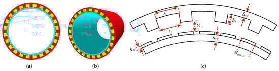
Figure 1.
Structure of the 5-MW PMVM for AZIPOD propulsion, (a) 2D, (b) 3D, (c) and defined dimension.
The rotor and stator are designed using laminated M400-50A steel with a thickness of 0.5 mm to reduce core losses, and segmented N48H magnets to minimize PM losses. For the same slot number and winding configuration, the normal three-phase machine can be redesigned as a dual three-phase machine by creating two separate winding sets with a phase-shifting angle, which improves the winding factor of the dual three-phase configuration. The stator of the DTP-PMVM consists of two overlapping distributed windings with a coil pitch of two and a fill factor of 0.6. The winding diagram, connection, and design parameters of the rotor and stator for the proposed DTP-PMVM are shown in Figure 2 and listed in Table 1.
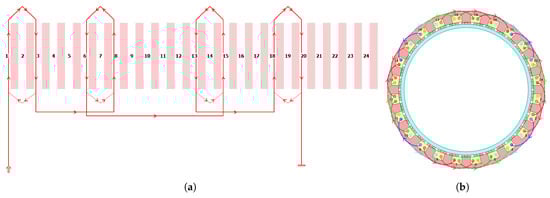
Figure 2.
Winding structure in DTP-PMVM with . (a) winding diagram for one phase, and (b) winding connection of all six phases.

Table 1.
Dimensions of the 5-MW DTP-PMVM with .
No Load and Full Load Test
The no-load analysis of the proposed DTP-PMVM is performed using FEM-based Motor-CAD analysis at the rated speed of 300 rpm. The induced voltage and flux linkage of all phases under no load conditions are shown in Figure 3, respectively. Under no load conditions, all six phases are balanced and symmetrical, with a 30-degree phase shift between the two winding sets, demonstrating the correct design and configuration of the dual three-phase system.
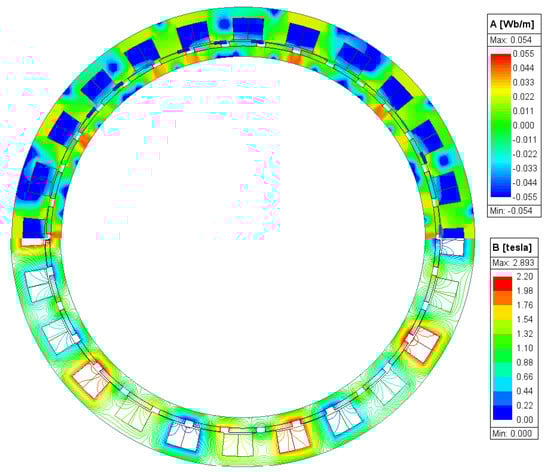
Figure 3.
Full load flux distribution of DTP-PMVM.
The full load analysis of the proposed DTP-PMVM is also performed, based on a rated current of 1610 A and a low current density of 2.96 A/m2 to make sure the machine operates without thermal issues, utilizing air-forced cooling. In addition, the thermal behavior of high-power propulsion motors is a critical factor that influences their operational reliability and lifespan. Recent advancements in battery and motor thermal management, such as micro-channel liquid cooling plate designs, provide promising solutions for efficient heat dissipation in high-density power systems [45]. The full load flux distribution is shown in Figure 4, where the flux path lines and flux density can be observed. The results indicate that the core is not saturated, even with the use of a very thin back iron, demonstrating that the machine operates effectively. The primary purpose of designing the DTP-PMVM is to enhance redundancy in ship propulsion. To evaluate this, the DTP-PMVM is tested under full-load and open-circuit conditions. The torque performance of the DTP-PMVM is assessed in both healthy conditions and with one winding set open-circuited, as shown in Figure 5. Under open-circuit conditions in one winding set, the proposed DTP-PMVM operates at half of the rated power with an acceptable ripple torque of less than 5%. All electromagnetic performance parameters of the proposed DTP-PMVM are presented in Table 2.
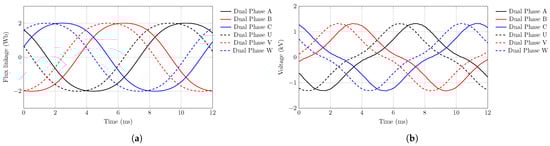
Figure 4.
No load comparison of DTP-PMVM (a) flux linkage comparison, and (b) induced voltage comparison.
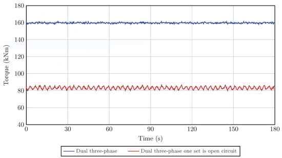
Figure 5.
Torque comparison of the DTP-PMVM in healthy conditions versus when one winding set is open-circuited.
Table 2.
Electromagnetic performance of DTP-PMVM with in 300 rpm.
3. Dual Three-Phase Machine Modelling Methods
DTP-PMs drives can be categorized into two types based on their winding configuration: symmetrical and asymmetrical [46,47,48,49]. Asymmetrical six-phase windings consist of two winding sets that are electrically displaced by 30 degrees. On the other hand, symmetrical windings feature a 60-degree electrical separation between the two sets. Furthermore, DTP-PMs provide flexibility in their winding configuration, allowing for either a single neutral point or two separate neutrals. This study focuses on an asymmetrical configuration with single neutral isolation, as shown in Figure 6. The motor is designed and optimized using the Non-dominated Sorting Genetic Algorithm (NSGA) and the Finite Element Method (FEM), with the design parameters detailed in Table 1 [44].
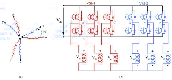
Figure 6.
(a) Asymmetrical arrangement of winding in DTP-Machine; (b) single neutral topology Voltage Source Inverter(VSI)-fed DTP-PMSM drive with stator winding connection. Reprinted with permission from Ref. [41]. 2023 IEEE.
DTP-PMs can be modeled using two approaches: vector space decomposition (VSD) and multiple individual three-phase models (MITPs). The MITP method is based on the synchronous dq-axis model of a three-phase machine, where multiple three-phase sub-machines form the basis. In contrast, the VSD method separates variables of different orders into orthogonal subspaces through mathematical transformations.
3.1. Modeling of MITP
Multiphase PMs consist of multiple three-phase sets, so their model can be viewed as the combination of the models of each individual three-phase machine, with additional coupling voltage terms. For each three-phase set, the machine model is developed in a synchronous dq reference frame. Specifically, the two individual three-phase models for a DTP-PM machine are illustrated in Figure 7 [18].
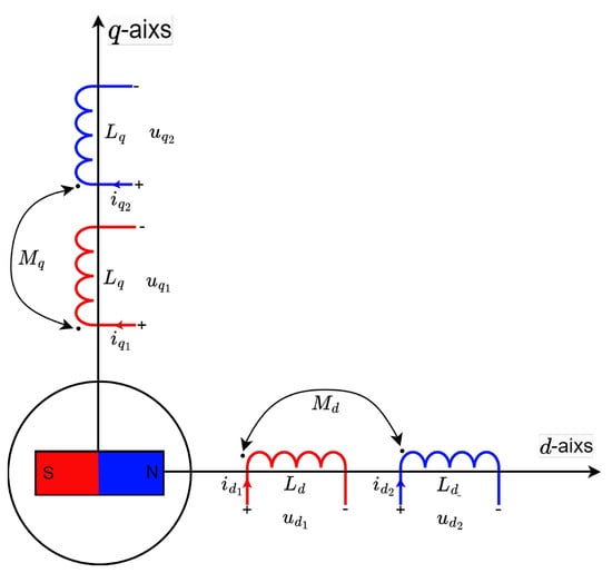
Figure 7.
The two separate three-phase models of DTP PMVMs represented in the dq-axis reference frame. Reprinted from Ref. [18].
The related voltage equations are given as follows [50]
and
where is the stator resistance, is the electrical angular speed, and is the permanent magnet flux linkage. The symbol s represents the derivative. The variables and refer to the -axis voltages and currents for the first winding set, while and represent the voltages and currents for the second winding set. The values and are the -axis inductances, and and are the -axis mutual inductances, indicating the magnetic coupling between the two winding sets. The electromagnetic torque for the multiple individual three-phase model can be expressed as
and the inductances are
where is the leakage inductance.
3.2. VSD Machine Model
Most studies on DTP-PMs simulation utilize the VSD approach due to its benefits, such as simplicity in modeling, ease of controller design, and improved harmonic control. The vector space decomposition (VSD) method [51] is widely used in modeling multiphase machines, as it simplifies the complex high-order electromagnetic system into two-order subsystems across various decomposed subspaces. This simplification allows for easier independent current control within these decoupled subspaces. The VSD transformation for the DTP machine is expressed as
where F is either current, flux linkage or the voltage. Using (7), the current and voltage can be decomposed into and components.
The DTP-PM model can be defined by the following models after the VSD conversion
and
where , , and are voltages, , , and are currents, R is the stator resistance, denotes the magnetic flux linkage, is rotor electrical speed, from (8), the current model for DTP-PMs can be rewritten as
The speed dynamic equation is described as
where , J, and B are mechanical angular velocity, total inertia and friction coefficient, respectively.The electromagnetic torque, , is given by
and
where p is the number of pole pairs of the rotor; thus, .
4. Model of Propeller Load Torque
The electrical system in a vessel with electric propulsion typically includes an onboard power system (an electric generator, distribution system, frequency converters, transformers, and switchboards for the distribution system). Figure 8 shows a condensed overview of the electrical systems in a ship using electric propulsion, illustrating the effects of various load conditions or load effects, such as the ocean environment, ship hull, and ship velocity, on the control of the propulsion motor [41]. Figure 9 describes the mathematical model for the propeller dynamic load [52]. The parameters of the propeller model are listed in Table 3. In Figure 9, Y is the propeller advance number, is the ship advance speed, is the ship efficient thrust force, is the resistive drag, and is the ship speed without considering the wake fraction, w, and it is bigger than [53].
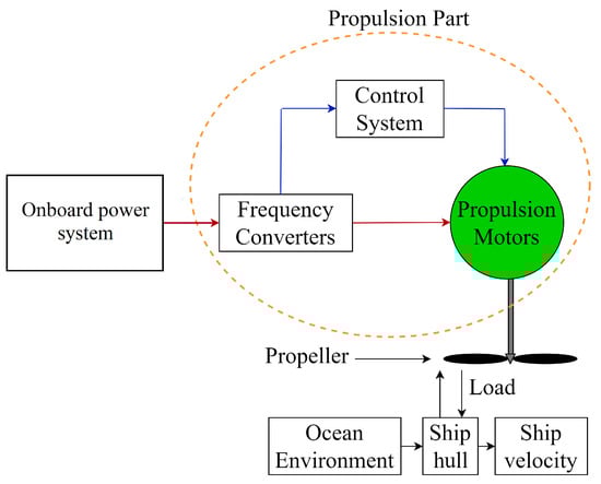
Figure 8.
Simplified electrical system layout in a ship using electric propulsion. Reprinted from Ref. [41].
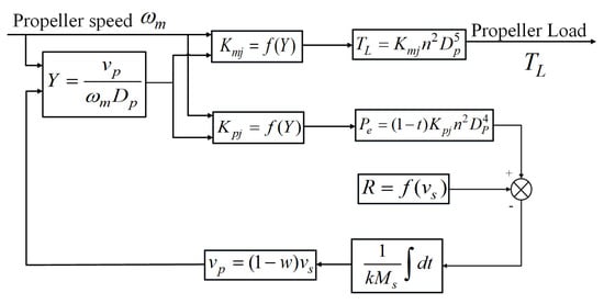
Figure 9.
Mathematical model of the propeller dynamic load.
Table 3.
Parameter Values.
5. Sensorless Control of DTP-PMVM
Figure 10 shows the main components of the sensorless vector control system for DTP-PMSM. The system includes five distinct feedback loops for controlling speed and current. These loops are linked to five comparators, which generate error signals for the respective controllers. The vector control strategy used in this system employs Clarke and Park transformations, along with their inverses, to enable smooth transitions between reference frames. The controllers adjust the inverter switching patterns based on the control signals to manage the inverter’s output, which is determined by the rotor speed and position. This is then compared with reference values, creating an error signal that prompts the controller to generate a corrective signal. The observer utilizes currents to estimate motor speed and position. Unlike traditional back-EMF observers, our proposed observer omits the PLL block. Notably, back-EMF observers require a quadrature PLL for reverse speed estimation, adding complexity, which is avoided in our method. In DTP-machine drive control, the PWM strategy follows the field-oriented principle, where the sub-plane serves as the stator reference voltage vector generated by the control system. Harmonics generated in the subspace cause losses, so it is necessary to cancel the average voltage vectors in this subspace to reduce these harmonics.
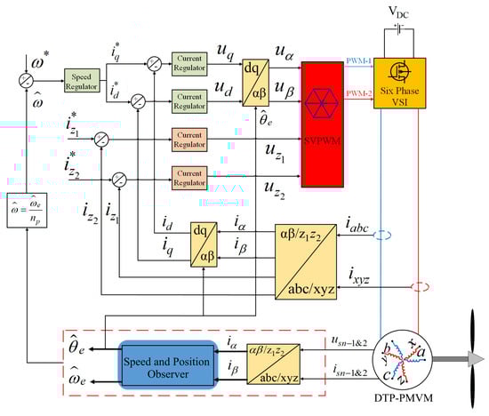
Figure 10.
Overall block diagram of sensorless vector control of DTP-PMVM. Reprinted from Ref. [41].
5.1. Prescribed-Time Sliding Mode Observer
In the following sections, we introduce two innovative designs. The first design features a prescribed-time observer that estimates motor speed and position, initially disregarding uncertainties in model parameters such as resistance and inductance. Next, we account for these uncertainties, recognizing that parameters may vary over time or with different motor operational points. Consequently, the observer is refined to function independently of system parameters, with unknown parameters estimated through adaptation laws. Both of these designs utilize a PI controller. Prior to starting the design of these observers, let us present the following definition and lemma.
Definition 1
([54]). The system described by is deemed prescribed-time input-to-state stable (PT-ISS) within the time interval if there exist a class function β and a class κ function γ for all such that:
where
- ;
- monotonically as .
Numerous functions meet the condition defined for μ. For instance, we select
with being an integer, then
Lemma 1
([55]). If for a nonlinear system there is a smooth positive definite radially unbounded function that satisfies
for positive constants and , then
and consequently it can be concluded that the system is prescribed-time input-to-state stable (PT-ISS) in time . Where and . The system settling time is independent of initial condition.
5.2. PT-SMO for Speed and Position Estimation of DTP-PMVM with Known Parameters
The model of DTP-PMVM can be expressed as
where and are defined
Based on (19), the following observer is proposed
where and is a compensation term that will be defined later. Based on (19) and (20), the derivative of the current estimation error is
where , , and in (13) are the estimation errors of , , and , respectively. , , and are the estimations of , , and , respectively.
Let us define the integral of current errors and
so, the derivative and second-order derivative of e can be expressed as
Based on the integral of estimation error and the prescribed-time sliding system defined in (17), the following sliding surface is introduced
where is a positive constant.
The time derivative of the sliding surface is
where , , and .
Now, the compensation term is proposed as
where is a positive constant.
The speed estimation prescribed-time adaptation law is proposed as
where is a positive constant matrix and is a constant gain. The estimated electrical angular position, , can be obtained as
Remark 1.
To ensure the stability of the proposed observer, it is assumed that the speeds of the DTP-PMVM and its derivative are bounded. Therefore, there exist positive constants ρ, ϱ and such that and . These assumptions are justified by the physical constraints of real-world systems, which prevent the speed from reaching infinity or undergoing abrupt changes.
Theorem 1.
The observer for speed and position, as described in (22), (24), (26), (27) and (29), is capable of accurately estimating the currents and speed of the DTP-PMVM at a predetermined time , regardless of the initial conditions. The estimation errors converge to a vicinity of zero with adjustable precision.
Proof.
The comprehensive proof is provided in Appendix A. □
5.3. Neural Network Based Adaptive PT-SMO for Speed and Position Estimation of DTP-PMVM with Unknown Variable Parameters
In this section, it is assumed that , and are time invariant and unknown. The observer will be modified to address the parameter uncertainty, and adaptation laws will be employed to estimate these unknown parameters. Now the following modified observer is proposed
similar the previous design where and are the compensation term that will be designed later. Based on (19) and (29), the derivative of the current estimation error is equal to
where and is the estimation of .
Furthermore, and are defined as
Given that and are unavailable, their values can be estimated using a Neural Network (NN), which leverages the universal approximation property inherent to neural networks.
, , , and denote the ideal neural-network weights and activation functions corresponding to the disturbance terms and , respectively, .
Given the Radial Basis Function (RBF) neural network’s simplicity and its promising capability in approximating nonlinear functions, we have employed it in our work. Consequently, and are modeled as
- Since the optimal weights are unknown a priori, we utilize adaptation laws derived from the Lyapunov function to train these neural networks online. The specific adaptation laws will be formulated subsequently. Let us define the sliding surface as (24). Based on (22), (23) and (24); one has
where
Now, let introduce the compensation term as follows
where is a small positive constant introduced to avoid division by zero.
The speed estimation prescribed-time adaptation law is proposed as
and are defined as in the previous section. The estimated electrical angular position, , can be obtained as follows
Now the adaptation laws for estimation of , i.e.; are proposed as follows:
The novel adaptation law for estimation of ideal weights of , is proposed as
In the stability analysis, , , and are assumed to be positive definite matrices, while , , and are chosen as positive constants.
Theorem 2.
The adaptive observer for speed and position, as outlined in Equations (29), (34), (35), and (36–38), effectively estimates the currents and the speed of the DTP-PMVM at a designated time , regardless of the initial conditions. The estimation errors diminish to near zero with a tunable degree of precision.
Proof.
The comprehensive proof is provided in Appendix B. □
6. Simulation Results and Analysis
To validate the effectiveness of the proposed observer, extensive simulations were performed in MATLAB/Simulink using the complete DTP-PMVM control architecture illustrated in Figure 10. This included the speed controller, current controller, PWM modulator, inverter, and observer. A variable-step solver (ode45) with a maximum step of was adopted to accurately capture fast electrical transients, while additional fixed-step simulations at were conducted to confirm that the conclusions remain consistent irrespective of the numerical integration scheme. The inverter was ideally modeled with a switching frequency of 10 kHz. The speed controller used a PI structure tuned based on the rated machine parameters shown in Table 2, and the estimated position provided by the observer was used as feedback for the current loop. To emulate realistic operating conditions, a small low-amplitude Gaussian noise was added to the measured currents. Additionally, the nonlinear inductance variation obtained from Motor-CAD, through the and maps, was included to introduce the structural mismatch that motivates the use of the adaptive ANNPT-SMO. For this study, the current references were selected as and .
The RBFNN used within the observer was configured with two inputs for each disturbance channel: for estimating and for estimating . The centres of the radial basis functions were uniformly distributed over the domain , and the widths were set to a constant value of . A total of five neurons () was selected to provide a practical compromise between estimation accuracy and computational demand. These settings were chosen empirically based on iterative testing and prior experience with similar nonlinear observer structures.
For the variable-parameter scenario, the prescribed time of the observer was set to . As expected, decreasing results in faster convergence but slightly increases the noise content in the estimated signals. This behaviour highlights the inherent trade-off between convergence speed and noise sensitivity, and the chosen value of was found to offer a suitable balance for the scenarios examined in this study.
This section presents a comprehensive evaluation of the proposed observers through two distinct simulation scenarios, highlighting the speed and rotor position tracking and estimation capabilities of the Prescribed-Time Sliding Mode Observer (PT-SMO) and the adaptive neural network-enhanced observer (ANN-PTSMO). The analysis emphasizes the observer’s performance under both fixed and time-varying motor parameters and provides a detailed technical discussion of convergence, robustness, and dynamic behavior.
6.1. Scenario 1: Fixed Motor Parameters
In the first scenario, the motor parameters are assumed constant, and the PT-SMO observer is applied. Figure 11a,b show the motor speed tracking performance under the prescribed reference trajectory. The results indicate that the PT-SMO observer achieves highly accurate speed tracking, with an average error of approximately 0.005 RPM. The speed trajectory closely follows the reference without significant overshoot or oscillations, demonstrating the robustness and stability of the prescribed-time sliding mode design.
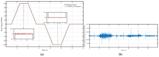
Figure 11.
(a) Speed tracking performance of the PT-SMO under fixed parameters and (b) Speed tracking error of the PT-SMO under fixed parameters.
Figure 12a,b present the speed estimation performance. The observer converges to the actual speed rapidly, with a maximum error of only 0.01 RPM. This confirms that the prescribed-time mechanism effectively guarantees that the estimation error reaches near zero within a predefined time interval, independent of the initial conditions. Such performance is particularly beneficial in applications requiring precise transient response and fast startup. Furthermore, the close alignment between the estimated and actual speed demonstrates the observer’s ability to maintain high accuracy during steady-state operation.
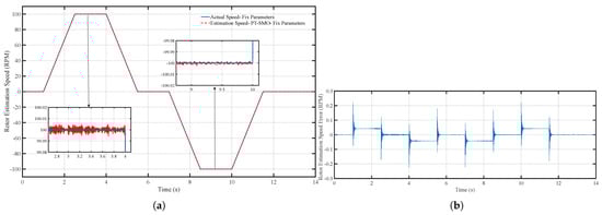
Figure 12.
(a) Speed estimation performance of the PT-SMO under fixed parameters and (b) Speed estimation error of the PT-SMO under fixed parameters.
Figure 13a,b depict the rotor position tracking and estimation performance. The position is accurately tracked, and the estimation error remains negligible throughout the simulation. The synchronized behavior between speed and position estimation highlights the effectiveness of the PT-SMO observer in providing high-fidelity state estimation. The minimal residual errors indicate that the observer’s sliding mode structure suppresses chattering and maintains smooth estimation trajectories, which is critical for torque control in practical sensorless motor applications. Overall, Scenario 1 demonstrates that the PT-SMO observer provides a reliable and precise baseline performance under ideal, fixed-parameter conditions.
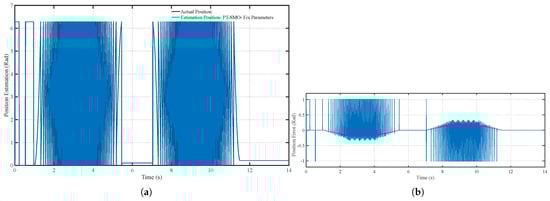
Figure 13.
(a) Position tracking performance of the PT-SMO under fixed parameters and (b) Position tracking error of the PT-SMO under fixed parameters.
6.2. Scenario 2: Time-Varying Motor Parameters
In the second scenario, the motor parameters vary with speed and current, reflecting realistic operating conditions derived from Motor-CAD simulations. Figure 14a,b illustrate that the PT-SMO observer maintains acceptable speed tracking, but its precision decreases compared to the fixed-parameter case. Figure 15a,b and Figure 16a,b show that both speed and position estimation errors increase under time-varying conditions, particularly during rapid changes in the reference trajectory. These results highlight the sensitivity of non-adaptive observers to parameter variations, as the fixed observer model cannot fully compensate for changes in motor characteristics. Despite this, the PT-SMO remains stable and free from oscillations, indicating inherent robustness in its sliding mode structure.
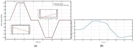
Figure 14.
(a) Speed tracking performance of the PT-SMO under variable parameters and (b) Speed tracking error of the PT-SMO under variable parameters.
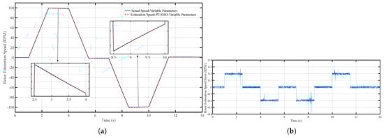
Figure 15.
(a) Speed estimation performance of the PT-SMO under variable parameters and (b) Speed estimation error of the PT-SMO under variable parameters.
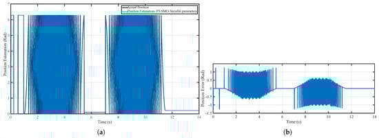
Figure 16.
(a) Position tracking performance of the PT-SMO under variable parameters and (b) Position tracking error of the PT-SMO under variable parameters.
To overcome the limitations of the PT-SMO under variable parameters, the ANN-PTSMO observer is employed. Figure 17a,b show that the adaptive observer significantly improves speed tracking performance, with a noticeable reduction in error compared to the PT-SMO. This enhancement is achieved by the neural network component, which adjusts the observer’s internal model online to account for variations in motor parameters. As a result, the observer maintains high precision even during rapid accelerations or decelerations.
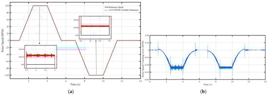
Figure 17.
(a) Speed tracking performance of the ANN-PTSMO under variable parameters and (b) Speed tracking error of the ANN-PTSMO under variable parameters.
Figure 18a,b illustrate the speed estimation performance of the ANN-PTSMO. The average estimation error is approximately 0.01 RPM, similar to the fixed-parameter scenario, demonstrating that the neural network adaptation successfully mitigates the effects of parameter variations. The observer’s convergence remains rapid and consistent, ensuring reliable speed estimation independent of initial conditions. Additionally, the ANN-PTSMO reduces transient overshoot and prevents oscillatory behavior often observed in conventional sliding mode observers when operating under dynamic conditions.
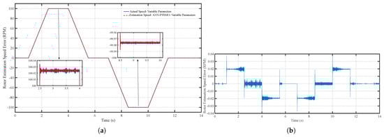
Figure 18.
(a) Speed estimation performance of the ANN-PTSMO under variable parameters and (b) Speed estimation error of the ANN-PTSMO under variable parameters.
Figure 19a,b present rotor position estimation and its error for the ANN-PTSMO. The results confirm that the adaptive observer accurately tracks the rotor position, with minimal and stable errors even when parameters change. The precise position estimation is crucial for maintaining efficient torque production and overall motor performance. The observer’s ability to adapt to time-varying parameters ensures that both speed and position estimates remain synchronized and accurate, a critical requirement for high-performance sensorless control.
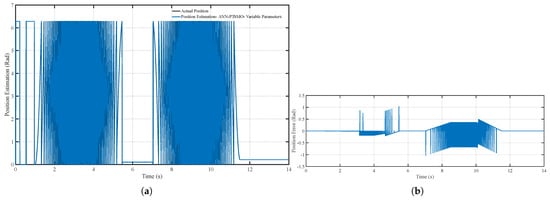
Figure 19.
(a) Position tracking performance of the ANN-PTSMO under variable parameters and (b) Position tracking error of the ANN-PTSMO under variable parameters.
Overall, the simulation results demonstrate that the PT-SMO provides reliable and precise estimation under fixed motor parameters, serving as a baseline for performance evaluation. Under time-varying parameters, the ANN-PTSMO significantly improves tracking and estimation accuracy by combining prescribed-time convergence with adaptive neural network compensation. The results highlight the effectiveness of the proposed observers in maintaining robust, high-fidelity state estimation across a range of operating conditions. This capability is essential for industrial and high-performance applications, where motor parameters may vary due to load changes, temperature fluctuations, or dynamic operating conditions, ensuring both stability and efficiency in practical sensorless control systems.
To provide a clearer quantitative comparison, Table 4 summarizes the key performance indicators of both observers under identical variable parameter conditions. It can be observed that the ANN-PTSMO achieves significantly lower average and maximum errors in both speed and position estimation compared to the PT-SMO. In addition, the convergence time is reduced by approximately 60%, confirming that the adaptive neural network mechanism effectively compensates for parameter variations and improves the accuracy and dynamic response of the estimation.
Table 4.
Performance Comparison Between PT-SMO and ANN-PTSMO.
7. Conclusions
This study presents a comprehensive investigation into sensorless control strategies for Dual Three-Phase Permanent Magnet Vernier Motors (DTP-PMVM) in the context of ship propulsion systems. The work integrates detailed motor design with advanced observer development, focusing on the Prescribed-Time Sliding Mode Observer (PT-SMO) and its adaptive neural network-enhanced extension (ANN-PTSMO).
Two simulation scenarios were conducted to evaluate the performance of the proposed observers. In the first scenario, with fixed and known motor parameters, the PT-SMO achieved highly accurate speed and position estimation, confirming its strong convergence characteristics under ideal conditions. In the second scenario, where motor parameters varied with operating conditions, the ANN-PTSMO demonstrated improved robustness and estimation precision due to its adaptive capability. The neural network adaptation effectively compensated for parameter variations while maintaining the prescribed-time convergence feature, ensuring consistent estimation performance.
Although the simulation results demonstrate the numerical feasibility and robustness of the proposed observers, several limitations must be acknowledged. The study is based entirely on MATLAB simulations and does not include hardware validation. Real-world factors such as measurement noise, sensor delays, inverter nonlinearities, and unmodeled mechanical effects were not considered. Therefore, the applicability of these methods to practical maritime propulsion systems should be viewed as promising but not yet experimentally confirmed. Moreover, the PT-SMO shows sensitivity to parameter variations, which can reduce estimation accuracy under dynamic conditions. The ANN-PTSMO addresses this issue by adapting its internal model, but its performance under extreme disturbances or significant model mismatches requires further investigation.
The proposed observers demonstrate enhanced tracking accuracy and improved robustness against parameter uncertainties. This highlights their potential for next-generation sensorless control of high-power marine propulsion drives.
Future work should focus on hardware-in-the-loop (HIL) or prototype-based experimental validation to confirm the practical effectiveness of the proposed observers. Further studies will also explore robustness against fault conditions, temperature-induced parameter drifts, and load fluctuations. Enhancing the neural network training mechanism to improve adaptation speed and stability, and combining the observer design with advanced control strategies such as model predictive control or robust control, are promising directions for achieving superior overall system performance. Evaluating scalability to larger propulsion systems and other types of electric machines will also be crucial for broader industrial adoption.
In summary, this study establishes a solid simulation-based foundation for prescribed-time and adaptive neural network observer design in DTP-PMVM drives, clarifies their strengths and limitations, and outlines a clear path toward experimental verification and real-world implementation in maritime propulsion systems.
Author Contributions
Conceptualization, V.T.; Methodology, V.T. and H.D.; Software, V.T., N.A. and H.D.; Validation, V.T., N.A. and H.D.; Formal analysis, V.T., N.A., H.D., M.J.K. and R.-J.W.; Investigation, V.T.; Resources, V.T.; Writing—original draft, V.T. and H.D.; Writing—review & editing, V.T., N.A., H.D., M.J.K. and R.-J.W.; Supervision, M.J.K. and R.-J.W.; Project administration, V.T., M.J.K. and R.-J.W. All authors have read and agreed to the published version of the manuscript.
Funding
This work was financially supported by the Department of Electrical and Electronic Engineering, Stellenbosch University in South Africa.
Data Availability Statement
The original contributions presented in this study are included in the article. Further inquiries can be directed to the corresponding author.
Conflicts of Interest
The authors declare no conflicts of interest.
Abbreviations
The following abbreviations are used in this manuscript:
| ANN | Artificial Neural Network |
| ANN-PTSMO | Artificial Neural Network Prescribed-Time Sliding Mode Observer |
| DTC | Direct Torque Control |
| DTP | Dual Three-Phase |
| DTP-PMSM | Dual Three-Phase Permanent Magnet Synchronous Motor |
| DTP-PMVM | Dual Three-Phase Permanent Magnet Vernier Motor |
| FEM | Finite Element Method |
| NN | Neural Network |
| PM | Permanent Magnet |
| PMVM | Permanent Magnet Vernier Motor |
| PMSM | Permanent Magnet Synchronous Motor |
| PTSMO | Prescribed-Time Sliding Mode Observer |
| PWM | Pulse Width Modulation |
| SMO | Sliding Mode Observer |
| SPMSM | Surface-mounted Permanent Magnet Synchronous Motor |
Appendix A. Theorem 1 Proof
Consider a Lyapunov function as
The time-derivative of V is equal to:
Substituting (25)–(28) into (A2) one has:
From Young inequality, the following inequalities can be derived.
where .
Now (A3) stands in the following inequality.
Define and . So,
Based on Lemma 1, V converge to an adjustable neighborhood of zero in a predefined time, i.e.,
Hence, and . From (24) we have
Define the following Lyapunov function.
Tacking time-derivative from (37) and some mathematical simplifications one has:
Utilizing Lemma 1 again, leads that . From (22) the boundedness of can be derived, i.e.; . Thus, the proof of Theorem 1 is completed.
Appendix B. Theorem 2 Proof
Define the following Lyapunov function:
Now compute the time-derivative of V.
Substituting (33)–(38) one has:
Based on the Young inequality, the following inequalities can be established.
with . and are the same as defined in Appendix A. The following inequality is evident based on [56].
Based on (A16)–(A21), (A15) can be write in the following form.
After defining and , one has:
According to Lemma converges to a adjustable vicinity of zero within a predetermined time, i.e.,
So and for where and . Using a method analogous to the one employed in the proof of Theorem 1, we can demonstrate that . Thus, the proof of Theorem 2 is completed.
References
- Burzanowska, H.; Sario, P.; Stulz, C. Redundant Drive with Direct Torque Control (DTC) and Dual-Star Synchronous Machine, Simulations and Verifications. In Proceedings of the EPE 2007—12th European Conference on Power Electronics and Applications, Aalborg, Denmark, 2–5 September 2007. [Google Scholar]
- Nanoty, A.; Chudasama, A. Design of multiphase induction motor for electric ship propulsion. In Proceedings of the Electric Ship Technologies Symposium (ESTS), Alexandria, VA, USA, 10–13 April 2011; IEEE: Piscataway, NJ, USA, 2011; pp. 283–287. [Google Scholar]
- Barcaro, M.; Bianchi, N.; Magnussen, F. Analysis and Tests of a Dual Three-Phase 12-Slot 10-Pole Permanent-Magnet Motor. IEEE Trans. Ind. Appl. 2010, 46, 2355–2362. [Google Scholar] [CrossRef]
- Wang, K.; Zhu, Z.Q.; Ren, Y.; Ombach, G. Torque Improvement of Dual Three-Phase Permanent-Magnet Machine with Third-Harmonic Current Injection. IEEE Trans. Ind. Electron. 2015, 62, 6833–6844. [Google Scholar] [CrossRef]
- Teymoori, V.; Kamper, M.J.; Wang, R.-J.; Kennel, R. Sensorless Control of Dual Three-Phase Permanent Magnet Synchronous Machines—A Review. Energies 2023, 16, 1326. [Google Scholar] [CrossRef]
- Zhang, Y.; Xu, S.; Song, Y.; Qi, W.; Guo, Q.; Li, X.; Kong, L.; Chen, J. Real-Time Global Optimal Energy Management Strategy for Connected PHEVs Based on Traffic Flow Information. IEEE Trans. Intell. Transp. Syst. 2024, 25, 20032–20042. [Google Scholar] [CrossRef]
- Kallio, S.; Andriollo, M.; Tortella, A.; Karttunen, J. Decoupled d-q model of double-star interior-permanent-magnet synchronous machines. IEEE Trans. Ind. Electron. 2013, 60, 2486–2494. [Google Scholar] [CrossRef]
- Demir, Y.; Aydin, M. Design, analysis and validation of a dual three-phase 72-slot, 12-pole permanent magnet synchronous motor. In Proceedings of the 2016 XXII International Conference on Electrical Machines (ICEM), Lausanne, Switzerland, 4–7 September 2016; pp. 1598–1603. [Google Scholar] [CrossRef]
- Guo, L.; Xu, J.; Wu, S.; Xie, X.; Wang, H. Analysis and Design of Dual Three-Phase Fractional-Slot Permanent Magnet Motor With Low Space Harmonic. IEEE Trans. Magn. 2022, 58, 8100112. [Google Scholar] [CrossRef]
- Barrero, F.; Duran, M.J. Recent advances in the design, modeling, and control of multiphase machines—Part I. IEEE Trans. Ind. Electron. 2016, 63, 449–458. [Google Scholar] [CrossRef]
- Ayati, M.; Rezaei, P.; Aghakhani, H. Modeling, fault detection, and stabilization of quadrotor unmanned aerial vehicle with rotor thrust deviation fault. Proc. Inst. Mech. Eng. Part I J. Syst. Control Eng. 2023, 237, 415–432. [Google Scholar] [CrossRef]
- Valencia, D.F.; Taylor, J.; Mohamadian, M.; Luedtke, D.; Emadi, A.; Bilgin, B. A comparative analysis for six-phase motor configurations. In Proceedings of the WCX SAE World Congress Experience, Detroit, MI, USA, 21–23 April 2020; p. 2020-01-0465. [Google Scholar] [CrossRef]
- Levi, E. Multiphase electric machines for variable-speed applications. IEEE Trans. Ind. Electron. 2008, 55, 1893–1909. [Google Scholar] [CrossRef]
- Zhu, Z.Q.; Xia, Z.P.; Wu, L.J.; Jewell, G.W. Analytical modeling and finite-element computation of radial vibration force in fractional-slot permanent-magnet brushless machines. IEEE Trans. Ind. Appl. 2010, 46, 1908–1918. [Google Scholar] [CrossRef]
- Xu, J.; Odavic, M.; Zhu, Z. An Advanced Harmonic Compensation Strategy for Dual Three-Phase Permanent Magnet Synchronous Machines Considering Different Angle Displacements. In Proceedings of the 2019 IEEE Energy Conversion Congress and Exposition, Baltimore, MD, USA, 29 September–3 October 2019; pp. 1797–1803. [Google Scholar]
- Arish, N.; Kamper, M.J.; Wang, R.-J. Electromagnetic analysis of flux barrier U-shaped permanent magnet vernier motor. In Proceedings of the 2021 International Aegean Conference on Electrical Machines and Power Electronics (ACEMP) and 2021 International Conference on Optimization of Electrical and Electronic Equipment (OPTIM), Brasov, Romania, 2–3 September 2021; pp. 198–204. [Google Scholar] [CrossRef]
- Antonysamy, R.P.; Lee, S.R.; Jung, S.Y.; Joo, Y.H. Performance enhancement using robust sliding mode approach-based current control for PMVG-WECS. IEEE Trans. Ind. Electron. 2023, 70, 10156–10166. [Google Scholar] [CrossRef]
- Zhu, Z.; Wang, S.; Shao, B.; Yan, L.; Xu, P.; Ren, Y. Advances in Dual-Three-Phase Permanent Magnet Synchronous Machines and Control Techniques. Energies 2021, 14, 7508. [Google Scholar] [CrossRef]
- Mi, Q.; Ma, R. A Novel Luenberger Observer for the Sensorless Speed Control of PMSM. PCIM Asia 2021. In Proceedings of the International Exhibition and Conference for Power Electronics, Intelligent Motion, Renewable Energy and Energy Management, Shenzhen, China, 9–11 September 2021; pp. 1–7. [Google Scholar]
- Li, C.; Elbuluk, M. A sliding mode observer for sensorless control of permanent magnet synchronous motors. In Proceedings of the Conference Record of the 2001 IEEE Industry Applications Conference. 36th IAS Annual Meeting (Cat. No.01CH37248), Chicago, IL, USA, 30 September–4 October 2001; Volume 2, pp. 1273–1278. [Google Scholar] [CrossRef]
- Zuo, Y.; Lai, C.; Iyer, K.L.V. A Review of Sliding Mode Observer Based Sensorless Control Methods for PMSM Drive. IEEE Trans. Power Electron. 2023, 38, 11352–11367. [Google Scholar] [CrossRef]
- Fan, L.; Yang, T.; Rashed, M.; Bozhko, S. Sensorless control of dual-three phase PMSM based aircraft electric starter/generator system using model reference adaptive system method. In Proceedings of the CSAA/IET International Conference on Aircraft Utility Systems (AUS 2018), Guiyang, China, 19–22 June 2018; pp. 787–794. [Google Scholar]
- He, Y.; Hu, W.; Wang, Y.; Wu, J.; Wang, Z. Speed and Position Sensorless Control for Dual-Three-Phase PMSM Drives. In Proceedings of the 2009 Twenty-Fourth Annual IEEE Applied Power Electronics Conference and Exposition, Washington, DC, USA, 15–19 February 2009; pp. 945–950. [Google Scholar]
- Qiu, X.; Ji, J.; Zhou, D.; Zhao, W.; Chen, Y.; Huang, L. A Modified Flux Observer for Sensorless Direct Torque Control of Dual Three-Phase PMSM Considering Open-Circuit Fault. IEEE Trans. Power Electron. 2022, 37, 15356–15369. [Google Scholar] [CrossRef]
- Teymoori, V.; Dastres, H.; Kamper, M.J.; Wang, R.J.; Arish, N. Enhanced Fast Terminal Sliding Mode Observer for Wide-Speed Sensorless Control of PM Vernier Ship Propulsion Machine Drives. In Proceedings of the 2023 International Aegean Conference on Electrical Machines and Power Electronics (ACEMP) and 2023 International Conference on Optimization of Electrical and Electronic Equipment (OPTIM), Istanbul, Turkiye, 1 September 2023; pp. 1–7. [Google Scholar] [CrossRef]
- Rezaei, P.; Lee, S.Y.; Cho, K.; Hahn, J.O. Robust control of Exo-Abs, a wearable platform for ubiquitous respiratory assistance. J. Dyn. Syst. Meas. Control 2025, 147, 021005. [Google Scholar] [CrossRef]
- Jin, D.; Liu, L. Adaptive Second-Order Disturbance Observer-Based Position Sensorless Drive Strategy for PMSM. IEEE Trans. Power Electron. 2024, 39, 16415–16428. [Google Scholar] [CrossRef]
- Ye, M.; Shi, T.; Li, C.; Yan, Y.; Xia, C. High-Precision Sensorless Control of High-Speed Permanent Magnet Synchronous Motor Based on the Prediction Methodology. IEEE Trans. Power Electron. 2024, 39, 11386–11397. [Google Scholar] [CrossRef]
- Lei, Z.; Xu, P.; Wu, X.; Yuan, K.; Wu, T.; Yu, X.; Yang, D.; Rong, F.; Huang, S. Sensorless Control for Bearingless Permanent Magnet Vernier Motor with Special Windings Based on Decoupling Sliding-Mode Observer. IEEE J. Emerg. Sel. Top. Power Electron. 2025. [Google Scholar] [CrossRef]
- Wang, D.; Liu, X. Sensorless Control of PMSM With Improved Adaptive Super-Twisting Sliding Mode Observer and IST-QSG. IEEE Trans. Transp. Electrif. 2025, 11, 721–731. [Google Scholar] [CrossRef]
- Wang, S.; Wang, H.; Tang, C.; Wang, L.; Zhu, Y.; Liu, H.; Wang, S. Sensorless Control Strategy for Permanent Magnet Synchronous Motor Based on Adaptive Non-Singular Fast Terminal Sliding Mode Observer. IEEE Trans. Appl. Supercond. 2024, 34, 5208905. [Google Scholar] [CrossRef]
- Tan, F.; Zhang, L.; Zhu, X.; Hang, J.; Ding, S. New Sliding Mode Predictive Observer for Variable-Leakage-Flux PMSM Sensorless Drive System. IEEE Trans. Ind. Electron. 2025, 72, 11130–11140. [Google Scholar] [CrossRef]
- Mi, Q.; Ma, R.; Zhang, Z.; Dong, H.; Zhang, G. Improved Sliding-mode Observer for PMSM Sensorless Indirect Field-Oriented Control. IEEE Trans. Transp. Electrif. 2025, 11, 13789–13801. [Google Scholar] [CrossRef]
- Zhu, X.; Huang, J.; Wang, P.; Li, Y.; Qi, G.; Wu, Y.; He, Y.; Zhang, Y. An Improved Sliding Model Observer Sensorless Control for PMSM Based on Fuzzy Logic Controller and DSOGI-FLL. IEEE Trans. Transp. Electrif. 2025, 11, 823–834. [Google Scholar] [CrossRef]
- Sun, X.; Wang, N.; Yao, M.; Lei, G. Position Sensorless Control of SRMs Based on Improved Sliding Mode Speed Controller and Position Observer. IEEE Trans. Ind. Electron. 2025, 72, 100–110. [Google Scholar] [CrossRef]
- Wang, D.; Li, B.; Zhao, Y. An Adaptive SMO Approach for Low-Chattering Sensorless Control of PMSM. IEEE Trans. Power Electron. 2025, 40, 15329–15338. [Google Scholar] [CrossRef]
- Song, C.; Hu, W.; Zhang, J.; Zhao, C.; Sun, X. A Gain-Adaptive High-Order Terminal Sliding Mode Observer Under SPMSM Sensorless Control. IEEE Trans. Power Electron. 2025, 40, 6555–6565. [Google Scholar] [CrossRef]
- Chang, J.-P.; Cheng, M.-Y. Rotor Position Estimation for a Position-Sensorless FOC PMSM Drive—A Super-Twisting-Based Sliding Mode Observer Approach. IEEE Access 2025, 13, 164540–164551. [Google Scholar] [CrossRef]
- Huang, H.; Li, K.; Yu, C.; Sun, Z.; Zhang, Y.; Zhao, Z.; Luo, B. Sensorless Control of Permanent magnet in-wheel motor for EVs Using Global Fast Terminal Sliding Mode Observer. ISA Trans. 2025, 160, 186–195. [Google Scholar] [CrossRef]
- Sun, H.; Zhang, X.; Liu, X.; Su, H. Adaptive Robust Sensorless Control for PMSM Based on Improved Back EMF Observer and Extended State Observer. IEEE Trans. Ind. Electron. 2024, 71, 16635–16643. [Google Scholar] [CrossRef]
- Teymoori, V.; Dastres, H.; Kamper, M.J.; Wang, R.-J.; Arish, N. Sensorless Control of DTP-PMSM Ship-Propulsion Drives by Using Nonsingular Fast Terminal Sliding Mode Observer. In Proceedings of the 2023 26th International Conference on Electrical Machines and Systems (ICEMS), Zhuhai, China, 5–8 November 2023; pp. 4257–4262. [Google Scholar] [CrossRef]
- Ding, H.; Wang, J.; Guo, X.; Li, S.; Guerrero, J.M. Fixed-Time Sliding-Mode Disturbance Observer-Based Finite-Time Backstepping Control for Current Source Rectifier. IEEE J. Emerg. Sel. Top. Power Electron. 2024, 12, 4767–4778. [Google Scholar] [CrossRef]
- Wang, B.; Shao, Y.; Yu, Y.; Dong, Q.; Yun, Z.; Xu, D. High-Order Terminal Sliding-Mode Observer for Chattering Suppression and Finite-Time Convergence in Sensorless SPMSM Drives. IEEE Trans. Power Electron. 2021, 36, 11910–11920. [Google Scholar] [CrossRef]
- Arish, N.; Kamper, M.J.; Wang, R.-J. Performance Comparison of 5-MW Normal and Dual Three-Phase PM Vernier Motors for Ship Propulsion. In Proceedings of the 2023 International Aegean Conference on Electrical Machines and Power Electronics (ACEMP) and 2023 International Conference on Optimization of Electrical and Electronic Equipment (OPTIM), Istanbul, Turkiye, 1 September 2023; pp. 1–8. [Google Scholar] [CrossRef]
- Qi, W.; Lan, P.; Yang, J.; Chen, Y.; Zhang, Y.; Wang, G.; Peng, F.; Hong, J. Multi-U-Style micro-channel in liquid cooling plate for thermal management of power batteries. Appl. Therm. Eng. 2024, 256, 123984. [Google Scholar] [CrossRef]
- Karttunen, J.; Kallio, S.; Peltoniemi, P.; Silventoinen, P.; Pyrhonen, O. Dual three-phase permanent magnet synchronous machine supplied by two independent voltage source inverters. In Proceedings of the International Symposium on Power Electronics, Electrical Drives, Automation and Motion, Sorrento, Italy, 20–22 June 2012; pp. 741–747. [Google Scholar]
- Singh, G.K.; Nam, K.; Lim, S.K. A simple indirect field-oriented control scheme for multiphase induction machine. IEEE Trans. Ind. Electron. 2005, 52, 1177–1184. [Google Scholar] [CrossRef]
- Bojoi, R.; Lazzari, M.; Profumo, F.; Tenconi, A. Digital field-oriented control for dual three-phase induction motor drives. IEEE Trans. Ind. Appl. 2003, 39, 752–760. [Google Scholar] [CrossRef]
- Slunjski, M.; Dordevic, O.; Jones, M.; Levi, E. Symmetrical/Asymmetrical Winding Reconfiguration in Multiphase Machines. IEEE Access 2020, 8, 12835–12844. [Google Scholar] [CrossRef]
- He, Y.; Wang, Y.; Wu, J.; Feng, Y.; Liu, J. A simple current sharing scheme for dual three-phase permanent-magnet synchronous motor drives. In Proceedings of the Annual IEEE Conference on Applied Power Electronics Conference and Exposition (APEC), Palm Springs, CA, USA, 21–25 February 2010; pp. 1093–1096. [Google Scholar]
- Tessarolo, A.; Bortolozzi, M.; Contin, A. Modeling of split-phase machines in Park’s coordinates. Part II: Equivalent circuit representation. In Proceedings of the IEEE Euro Conference, Zagreb, Croatia, 1–4 July 2013; pp. 1314–1319. [Google Scholar]
- Ren, J.J.; Liu, Y.C.; Wang, N.; Liu, S.Y. Sensorless control of ship propulsion interior permanent magnet synchronous motor based on a new sliding mode observer. ISA Trans. 2015, 54, 15–26. [Google Scholar] [CrossRef]
- Sulligoi, G.; Vicenzutti, A.; Menis, R. All electric ship design: From electrical propulsion to integrated electrical and electronic power systems. IEEE Trans. Transp. Electrif. 2016, 2, 507–521. [Google Scholar] [CrossRef]
- Song, Y.; Wang, Y.; Krstic, M. Time-varying feedback for stabilization in prescribed finite time. Int. J. Robust Nonlinear Control 2019, 29, 618–633. [Google Scholar] [CrossRef]
- Li, W.-Q.; Krstic, M. Stochastic nonlinear prescribed-time stabilization and inverse optimality. IEEE Trans. Autom. Control 2021, 67, 1179–1193. [Google Scholar] [CrossRef]
- Li, Y.X. Command filter adaptive asymptotic tracking of uncertain nonlinear systems with time-varying parameters and 577 disturbances. IEEE Trans. Autom. Control 2021, 67, 2973–2980. [Google Scholar] [CrossRef]
Disclaimer/Publisher’s Note: The statements, opinions and data contained in all publications are solely those of the individual author(s) and contributor(s) and not of MDPI and/or the editor(s). MDPI and/or the editor(s) disclaim responsibility for any injury to people or property resulting from any ideas, methods, instructions or products referred to in the content. |
© 2025 by the authors. Published by MDPI on behalf of the World Electric Vehicle Association. Licensee MDPI, Basel, Switzerland. This article is an open access article distributed under the terms and conditions of the Creative Commons Attribution (CC BY) license (https://creativecommons.org/licenses/by/4.0/).