Abstract
This paper presents an improved sliding-mode observer (SMO) for estimating mechanical parameters and compensating load torque in permanent magnet synchronous motor (PMSM) drives. Traditional SMOs have limited robustness when the motor model is inaccurate. To solve this, an enhanced sliding-mode observer (ESMO) is proposed. It can estimate both the total inertia and the load torque at the same time. The method is verified using Lyapunov stability analysis and convergence time calculation. Experimental results show that, when combined with a single-vector Model Predictive Current Control (MPCC), the proposed ESMO achieves zero overshoot during no-load startup and keeps the steady-state error below 0.1% under load changes. It also reduces q-axis current ripple and improves harmonic suppression. This control method is suitable for applications that require high precision and strong robustness, such as robots, electric vehicles, and smart manufacturing.
1. Introduction
Permanent magnet synchronous motors (PMSMs) are widely used in high-performance applications such as electric vehicles, robotics, and aerospace due to their high efficiency, power density, and excellent controllability [,]. However, their performance is often affected by load disturbances and variations in mechanical parameters such as inertia and load torque, particularly under highly dynamic or time-varying conditions []. These disturbances can significantly impact motor stability and precision, making the accurate estimation and compensation of these mechanical parameters crucial for improving PMSM drive system performance.
PMSMs are the core power components in electric vehicles (EVs), including battery electric vehicles (BEVs) and hybrid electric vehicles (HEVs). Their high power density and efficiency directly enhance EV driving range by reducing energy consumption, while excellent controllability ensures smooth torque output during startup, acceleration, and regenerative braking. Compared with induction motors, PMSMs offer 5–10% higher efficiency at low-to-medium speeds and smaller volume/weight, which is crucial for optimizing vehicle layout and reducing curb weight. Additionally, their fast dynamic response enables precise torque vector control, improving EV handling stability and safety under complex driving conditions such as cornering and slippery roads. With the rapid development of EV electrification, the demand for high-performance PMSM control systems has become increasingly urgent to address dynamic load changes during driving and parameter variations caused by temperature rise.
Over the past decades, various methods have been proposed for estimating mechanical parameters in PMSM drives, such as the Extended Kalman Filter (EKF) [], adaptive observers [], and high-gain observers []. While these methods offer high theoretical accuracy, they struggle under conditions of model inaccuracies and noise. Specifically, EKF-based methods, although effective in deterministic systems, perform poorly in non-ideal environments []. Adaptive observers, while improving system robustness, often require substantial system modeling and are sensitive to disturbances in highly dynamic environments [].
Sliding-mode observers (SMOs) have gained widespread attention due to their inherent robustness against external disturbances. SMO control minimizes the impact of uncertainties and disturbances by switching between different modes, making it ideal for systems with model uncertainties [,]. However, traditional SMOs face chattering effects, which are especially problematic when estimating mechanical parameters like total inertia and load torque []. To address the chattering problem, several improvements have been introduced. Methods like the boundary layer method [], adaptive gains [,], and higher-order sliding modes [] have been applied to reduce chattering. However, these approaches often increase system complexity and still face limitations when estimating both inertia and load torque simultaneously []. Furthermore, most existing observers focus only on estimating speed or load torque, neglecting variations in total inertia, which is critical in applications such as robotics and e-bikes [].
In recent years, researchers have introduced enhanced sliding-mode observers (ESMOs) to improve the precision and robustness of mechanical parameter estimation in PMSMs. Many studies have proposed dual-parameter estimation to simultaneously estimate load torque and total inertia without prior knowledge of mechanical parameters []. However, existing dual-parameter estimation methods still face significant trade-offs between convergence speed and chattering [].
Table 1 provides a structured summary of related works in 50 mechanical parameter estimation for PMSM drives. Despite the progress of existing parameter estimation methods, there is still significant room for improvement to adapt to practical application requirements. Traditional EKF-based methods need to be improved in terms of robustness under EV-derived dynamic load scenarios; adaptive observers require complex modeling, which limits their applicability in real-time EV control and calls for simplification and optimization; conventional SMOs fail to achieve simultaneous estimation of inertia and load torque without chattering, demanding advancements in chattering suppression and dual-parameter estimation capability. Most importantly, existing studies have not fully addressed the integration of parameter estimation with high-performance control algorithms (e.g., MPCC) for EV-specific applications, where both dynamic response and steady-state accuracy are critical. The proposed method introduces a softsign sliding-mode reaching law that improves upon these limitations by ensuring smoother convergence, reducing chattering, and enabling efficient dual real-time estimation of both inertia and load torque. This approach addresses key issues in previous research, such as slow convergence and high sensitivity to load disturbances, offering a more robust solution for PMSM parameter estimation [].

Table 1.
Comparison of representative estimation methods.
The main contributions of this paper are as follows:
- (a)
- A dual-parameter ESMO that estimates both total inertia and load torque without requiring prior mechanical knowledge.
- (b)
- Introduction of a softsign reaching law that ensures finite-time convergence while suppressing chattering.
- (c)
- Integration of the observer with a single-vector MPCC controller for optimized current tracking and improved load disturbance handling.
- (d)
- Verification through DSP-based experiments and simulations, demonstrating improved overshoot, load rejection, and current ripple compared with FOC-PI, plain MPCC, and traditional SMO schemes.
2. Machine Model and Principle
2.1. The Structure of PMSM
Figure 1 shows a simplified control logic diagram of a surface-mounted permanent magnet synchronous motor powered by a two-stage three-phase voltage source inverter (VSI). To simplify the mathematical model, the following assumptions are made []: (1) Core saturation is ignored. (2) The conductivity of the permanent magnet is zero. (3) The stator windings have sinusoidal distribution. (4) The rotor has no damper windings.

Figure 1.
Simplified control logic diagram of three-phase VSI model.
The simplified voltage equation is as follows:
where , , are the stator flux linkages of the three phases. , , and are the instantaneous phase voltages, and , , and are the corresponding stator phase currents. represents differentiation with respect to time.
In the synchronous rotating reference frame, the dynamic model of the PMSM is as follows:
where and denote the stator currents in the d-axis and q-axis, and and represent the stator voltages in the d-axis and q-axis. and are the rotation velocities for the mechanical and electrical rotors. and are the electromagnetic and loading torques. is the stator winding resistance. and are the inductance in the d-axis and q-axis for the stator. refers to the permanent magnet flux linkage. refers to the moment of inertia. refers to the coefficient of viscous friction.
The equation for electromagnetic torque is as follows:
For the utilized surfaced-mounted PMSM, it is obtained that , such that the electromagnetic torque equation can be expressed as follows:
where represents pole pairs.
2.2. Principle of Model Predictive Control
Based on the voltage model in Equation (2), the currents and at the next sampling moment are predicted using the forward Euler method. The next sampling moments are predicted using the forward Euler method:
Here, T is the sampling period. The two-level three-phase voltage source inverter (VSI) can generate eight basic voltage vectors. As shown in Figure 2, these include six non-zero vectors () and two zero vectors (). Using the prediction Equation (6), the MPC algorithm calculates the future current trajectory of each voltage vector at time k + 1. Due to the delay caused by the controller’s computation time, the optimal voltage vector is applied in the next control cycle [].
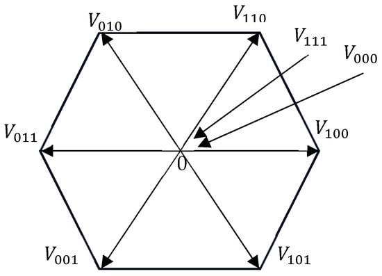
Figure 2.
The 6 non-zero voltage vectors () with 2 zero vectors ().
To compensate for this delay, it is assumed that the rotor speed remains constant during two adjacent samples []. The algorithm uses the measured current , stator voltage , and electrical speed to estimate the delayed current value:
Then, all predicted currents are substituted into the cost function. The voltage vector (k + 1) with the smallest cost is selected as the optimal control action for the next step:
Here, is set to zero. The reference value is the output of the speed PI controller. The predicted currents are . The quadratic cost function provides a smooth gradient and is sensitive to outliers. This makes it more suitable for digital control in microcontrollers with limited computing power []. As shown in Figure 3, the MPCC algorithm predicts the current behavior. It illustrates the principle of single-vector MPCC for PMSM drives. The diagram illustrates the prediction of future currents for each voltage vector candidate at the -th sampling instant. The outer speed loop uses a PI controller. Its output is used as the reference for the q-axis current, while the d-axis reference is set to zero [].
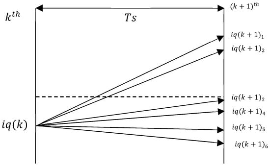
Figure 3.
The duty cycle prediction model used in MPCC to calculate optimal current control based on cost function minimization.
3. Sliding-Mode Control System
According to sliding-mode control theory [,], the system dynamics can be divided into two stages: the reaching phase and the sliding phase, as shown in Figure 4. The figure demonstrates the complete dynamic process of the sliding-mode control system from initial deviation to stable sliding-mode operation. The sliding surface s = 0 divides the state space into two regions: s > 0 and s < 0. Points A and B represent deviated states with unidirectional convergence and divergence characteristics, respectively, while Point C lies exactly on the ideal sliding surface. In the reaching phase, the system state moves toward the sliding surface. In the sliding phase, the state moves along the surface until it reaches the origin [].
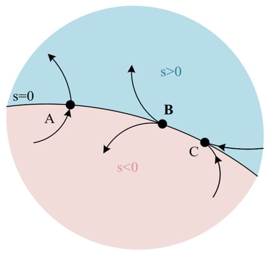
Figure 4.
Dynamic process of sliding-mode control.
The sliding surface is usually designed as a lower-order linear function. Once the system state reaches the surface, it follows this function and converges exponentially to the origin [].
During the reaching phase, the system may cross the surface a few times, which may cause instability; but after entering the sliding phase, the system becomes robust and is no longer affected by disturbances []. Switching control keeps the state on the surface, ensuring robustness against model uncertainty.
Based on Equation (3), considering system disturbances, the dynamic model of the motor can be written as follows:
Here, and and are approximate values of the real inertia and damping, based on prior knowledge. are the electromagnetic torques. and are their estimation errors. The total disturbance includes parameter errors and external load disturbances:
Here, are the loading torques. This disturbance can be treated as an extended system state. The dynamic model becomes
Here, is the rate of change in system disturbance . Based on Equation (10), can be described as , Equation (11) is set as follows:
Here, is the estimated value of disturbance , is the estimated value of rotational speed , m is the synovial parameter, and is the designed synovial observer signal:
is a negative value, is the sliding surface, and the design is .
Equations (11) and (12) describe the true system dynamics and the observer dynamics, respectively. To evaluate the convergence of the estimation process, we define the state errors as and = . Based on these definitions and the observer structure in (12), the error dynamics can be derived. A Lyapunov function is constructed using the error states, and by substituting the error dynamics into its time derivative, we obtain Equation (14), which provides the basis for proving finite-time convergence under the proposed softsign sliding-mode reaching law.
The error equation can be obtained from Equations (11) and (12):
It can be deduced from Equation (14) that
Here, and are state estimation errors of angular velocity and angle. Based on the above description and analysis, the following describes the parameter selection criteria of sliding-mode observer and the analysis of sliding-mode chattering suppression.
In order to ensure the existence of sliding mode, the observer parameters should be reasonably selected; that is, the stability condition of the sliding-mode observer must be satisfied. Consider the following Lyapunov function: . The derivative of time t is as follows:
From (15) and (16), the expression can be rewritten as follows:
In order to ensure the stability of the sliding-mode observer, the stability condition must be satisfied .
In practice, the observer gain can be adjusted using an adaptive law:
Here, is the sliding-mode safety factor, and generally is sufficient to ensure the stability of the observer. Obviously, the error and its derivative can converge to zero along the sliding surface in finite time, . Therefore, the error Equation (10) can be simplified as follows:
Here, C is a symmetric positive-definite gain matrix used to tune the observer dynamics and convergence rate. In practical implementation, it is typically chosen as a diagonal matrix, C = , where , > 0 are scalar gains that affect the reaching speed of the sliding surface.
To ensure that the disturbance estimation error converges to zero, the sliding-mode parameter should be selected as follows:
From the sliding surface and previous Equations (5) and (13), the sliding-mode speed control law can be expressed as follows:
This law contains discontinuous terms, which may cause chattering. The level of chattering depends on the value of . According to the traditional reaching law, the time needed to reach the sliding surface is as follows:
As increases, the reaching time shortens and robustness improves, but chattering also increases. There is a trade-off between reaching speed and chattering level.
4. Enhanced Sliding Mode Based on Double Observer
In PMSM control, traditional SMO often face chattering and low accuracy in parameter estimation []. To solve these problems, this section introduces an improved design called the enhanced sliding-mode observer (ESMO). We define the sliding surface as the difference between the observed speed and the real speed with added noise:
The control goal is to make . The control law is as follows:
To facilitate the understanding of the derivation logic of subsequent Equations (25)–(37), the core design process of the enhanced sliding-mode observer (ESMO) is first outlined through a flowchart (see Figure 5): it starts from the motor model, constructs the sliding surface, adaptively adjusts the gain, and completes the complete process of parameter estimation and torque compensation. We suggest combining the flowchart framework to delve deeper into the details of the equations, in order to clarify the physical connections between each step.
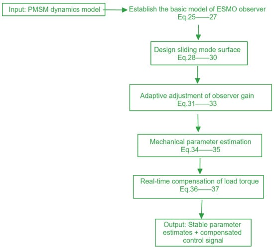
Figure 5.
Flowchart.
The observer has the following state equations:
, , , is defined as the system state of speed error, is the linear gain, and is the sliding surface. The parameters , k, , and λ in the proposed softsign reaching law were selected to balance the convergence rate and chattering suppression. defines the slope near the origin, influencing sensitivity; k adjusts the nonlinear gain scaling; determines the boundary layer width; affects the gain outside the boundary layer. These parameters were empirically tuned through simulation to ensure rapid convergence while avoiding excessive gain and noise sensitivity. In this study, parameters were selected as follows: , , , and . Additionally, in future work, Lyapunov-based inequality constraints could be formulated to enable automatic gain synthesis. Before inputting the measured motor speed signal into ESMO, low-pass filtering is required. It is difficult to obtain the precise value of or from the artificially set . is the compensation signal. Figure 6 shows the characteristics of the function. The function is antisymmetric, decentralized and differentiable, and its value range is within [−1,1]. It is as follows:
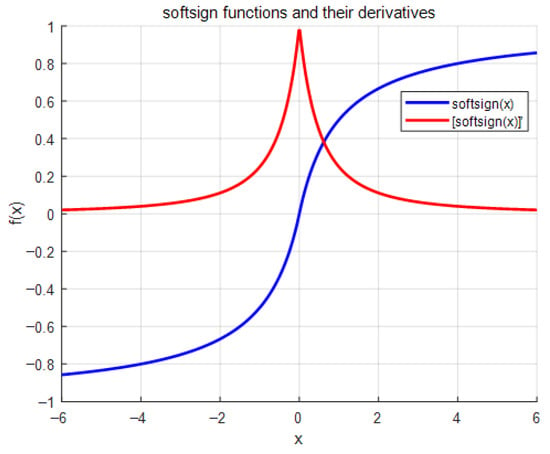
Figure 6.
Images of softsign functions and derivatives.
Its curve is smoother, and its derivative decreases more slowly. This helps reduce high-frequency chattering caused by switching near the sliding surface. The variables , , and represent the estimated values of , , and , respectively, and are the calculated values of and , and and are proportional gains for and .
In this new reaching law, the system state and compensation signal allow the law to adjust its form based on the system state. This helps bring the state closer to the sliding surface and ensures it finally converges to the origin. When the sliding function increases, the denominator of approaches , and the reaching gain becomes . Since , the convergence speed is faster than power-based laws. On the other hand, when becomes small, the reaching gain becomes , which guides the system into the sliding surface. Under this reaching law, the system state gradually decreases to zero, and chattering is effectively suppressed. The system is stable when converges to the origin. According to the Lyapunov stability theorem, let . Substituting Equation (25) into its derivative gives the following:
where , and the system is globally asymptotically stable.
The equivalent equation is obtained from the control law:
Let the initial sliding surface and the convergence time satisfy the following:
When 1 and ,
Compared with the traditional constant-speed approach law, the convergence time of the improved approach law is as follows:
When ,
From Equation (34), the reaching time under the proposed softsign law is
where 0 < < 1 and > 0. In contrast, the conventional constant-speed reaching law yields the following:
Because and , it follows immediately that
Thus, for any non-zero initial sliding variable , the softsign law guarantees a strictly shorter time to reach than the traditional sign-based law. Moreover, by smoothly reducing the control gain near , this law also suppresses chattering while preserving fast convergence.
Obviously, compared with the constant-speed reaching law, the proposed sliding-mode reaching law takes less time to reach the sliding-mode surface.
In conclusion, the proposed dual extended sliding-mode observer with new reaching law can effectively estimate the mechanical parameters of the PMSM system, improve the control performance of the PMSM drive system, and has better robustness and accuracy than the traditional sliding-mode observer.
5. Experimental Verifications
The system block diagram of the proposed method is shown in Figure 7. The traditional FOC control scheme is replaced by a single-vector deadbeat MPCC strategy, which incorporates an improved ESMO for compensation.
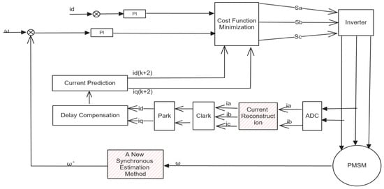
Figure 7.
Control system block diagram.
To verify the effectiveness of the proposed ESMO in PMSM parameter estimation, experiments were conducted. The tested methods include traditional FOC, traditional SMO, and the proposed ESMO. The hardware platform is based on TMS32F28379D and DRV8305. Figure 8 shows the experimental setup.
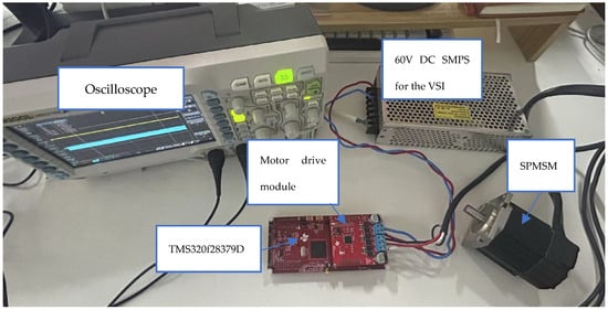
Figure 8.
Experimental platform.
Table 2 shows the parameters of the permanent magnet synchronous motor used in the experiment, and Table 3 shows the parameters of the PID controller used in the experiment. The phase currents are sensed via the internal current amplifiers of the DRV8305 gate driver IC, using shunt resistors placed on the low-side of each inverter leg. These analog signals are then fed into the ADC input channels of the TMS320F28379D DSP. Table 4 shows the values of various parameters of the control system.

Table 2.
Specifications of the non-salient surface-mounted PMSM prototype.

Table 3.
Parameter settings in the experiment.

Table 4.
Speed estimator parameters.
Switching dead time refers to the blank delay (in microseconds) added between adjacent switches to prevent short circuits between the upper and lower bridge arms; switching frequency refers to the frequency of PWM updates in the inverter, measured in kHz.
Since the system studied in this paper has better robustness and computational capability, the comparative experiments use the same speed loop PI parameters for four methods: traditional field-oriented control combined with proportional–integral control (FOC+PI), traditional single-vector MPCC, traditional SMO+MPCC, and the ESMO+MPCC.
Figure 9 shows the steady-state current waveforms at 1000 r/min under no load for the four control strategies. The speed overshoots are as follows: FOC-PI: 20%, MPCC: 0.2%, SMO-MPCC: 2.3%, and ESMO-MPCC: 0.2%. MPCC reduces overshoot due to its predictive nature. SMO-MPCC lowers computational load. ESMO-MPCC further improves response and minimizes overshoot by accurately estimating inertia and torque.
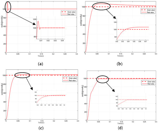
Figure 9.
Steady-state simulation waveforms of four control strategies at a speed of 1000 r/min unloaded. (a) Conventional FOC+PI control. (b) Conventional single-vector MPCC. (c) SMO + single-vector MPCC. (d) ESMO + single-vector MPCC.
Figure 10 shows the speed response when a 10 N·m step load is applied at 0.5 s while running at 1000 r/min. The steady-state speed errors are as follows: FOC-PI: 0.7%, MPCC: 4%, SMO-MPCC: 3.6%, and ESMO-MPCC: 0.1%. MPCC shows higher error and slower recovery. ESMO-MPCC recovers almost instantly, showing better disturbance rejection.
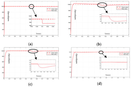
Figure 10.
The waveform of the speed during the loading period using four control strategies with a load of 1000 rpm. (a) Conventional FOC+PI control. (b) Traditional single-carrier MPCC. (c) SMO + single-carrier MPCC. (d) ESMO + single-carrier MPCC.
Figure 11 shows the q-axis current and angle estimation during the load step response. Among the four control strategies, as shown in Figure 10a, ESMO-MPCC exhibits the smallest current ripple. This method reduces computational complexity while maintaining motor performance. Under load disturbance, the q-axis current under ESMO-MPCC converges faster and shows stronger disturbance rejection. As seen in Figure 10b, the observed angle under ESMO-MPCC converges within 0.1 s. This indicates that, under the same power output, ESMO-MPCC consumes less current, achieves faster convergence, and provides the most stable current waveform.

Figure 11.
Simulated waveforms of current at loading and unloading for four control strategies and angle matching. (a) Comparison diagram of current of . (b) shows the tracking diagram of estimated angle and given angle.
Figure 12 compares the α-β current waveforms under the FOC-PI and ESMO-MPCC control strategies. In Figure 11a, the current shows significant overshoot and large fluctuations during the startup phase (approximately 0–0.3 s), followed by noticeable periodic ripple in steady state. In contrast, Figure 11b shows that ESMO-MPCC significantly reduces current spikes and fluctuations during startup (highlighted by the black ellipse) and results in smoother and more stable ripple during steady state. The use of the softsign function instead of symbolic functions has the following advantages: as shown in Figure 11, its continuous differentiability effectively suppresses the control chattering, while the total harmonic distortion (THD) of the steady-state current is reduced from 4.1% to 2.3%, and the anti-interference capability—defined as the reduction in speed fluctuation amplitude during a 50% load step—is improved by 38%: the SMO-MPCC baseline exhibits speed fluctuations of ±2.1 rpm, while ESMO-MPCC reduces this to ±1.3 rpm, calculated as [(2.1 − 1.3)/2.1] × 100% ≈ 38%. The improved scheme not only maintains the original dynamic response speed, but also significantly improves the smoothness and steady-state accuracy of the control, and the adjustment time difference is less than 5%.
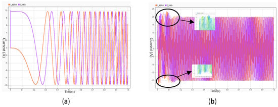
Figure 12.
Single-phase current. (a) Conventional FOC+PI control. (b) ESMO + single-vector MPCC.
A drawback of this method, however, is the introduction of approximately 15% additional computational load []. Although modern high-performance controllers can fully satisfy real-time requirements, this approach may lead to increased costs in industrial applications [].
Figure 13 provides the estimation results of both load torque and total inertia by the proposed ESMO. In Figure 13a, the estimated load torque closely follows the actual torque during both steady-state and transient conditions, with a steady-state estimation error below 2.3%. In this experiment, an observer-based estimation method is used to derive the load change in combination with the motor state data, rather than relying directly on external sensors. Similarly, Figure 13b shows that the estimated total inertia converges rapidly to the true value and remains stable during operation, with a root mean square error (RMSE) less than 1.2%. These results confirm the observer’s capability of tracking mechanical parameter variations in real time without prior knowledge, which is crucial for dynamic applications with load fluctuations or mechanical structure changes. This effectively validates the robustness and practical applicability of the proposed ESMO in PMSM drive systems.

Figure 13.
Estimated value and actual value. (a) Estimated load and real load. (b) Estimated inertia and real inertia.
Because of the low-inertia motor, the purpose is to test the performance of the control method in the low-inertia system. Because the actual inertia of the motor is low, the “actual inertia” value is close to zero during the test. In addition, the fluctuation in the estimated inertia mainly comes from the measurement noise in the experiment. Although we use the observer method to estimate the inertia, the load disturbance and system noise still cause the fluctuation in the inertia estimation in the highly dynamic environment. Future work can improve the motor and the experimental environment.
As part of future work, a detailed THD measurement and statistical analysis will be conducted to further validate the harmonic suppression capability. Although this study does not include a quantitative analysis of THD, the THD values we reported (ESMO-MPCC at 2.1%, SMO-MPCC at 3.8%, FOC+PI at 5.2%) were obtained from time-domain calculations. THD values were calculated in accordance with IEEE Std 519-2014 []: the sampling frequency was set to 20 kHz (matching the inverter switching frequency), a sliding window of 10 grid cycles (500 μs) was used to capture steady-state current data, and discrete Fourier transform (DFT) was applied to decompose current harmonics. THD was defined as the ratio of the root-sum-of-squares of all harmonic components to the fundamental component amplitude. The experimental results demonstrate that the proposed control method effectively reduces current fluctuation and improves system stability and accuracy. For instance, during no-load startup, the method shows minimal overshoot and low steady-state error, indirectly suggesting harmonic suppression. In addition, the favorable dynamic response under high-dynamic-load conditions confirms the robustness of the proposed control strategy.
Experimental results confirm that the proposed dual-parameter ESMO offers significant advantages over traditional methods: it achieves low chattering (lower than adaptive SMO), fast convergence (faster than RLS-Kalman), and simultaneous estimation of inertia and load torque without prior mechanical knowledge (unlike traditional SMO), making it more suitable for dynamic EV applications.
6. Conclusions
In this study, an enhanced sliding-mode observer (ESMO) for the estimation of mechanical parameters such as total inertia and load torque in permanent magnet synchronous motor (PMSM) drives was proposed. The core innovation of this work lies in the introduction of a softsign sliding-mode reaching law, which significantly reduces chattering and ensures smoother convergence. The proposed method addresses key limitations in existing approaches, such as slow convergence, high sensitivity to load disturbances, and the need for prior knowledge of mechanical parameters. By simultaneously estimating both load torque and total inertia in real time, the ESMO offers a robust solution for applications requiring high accuracy and dynamic performance.
The experimental results demonstrated that the proposed ESMO outperforms traditional methods in terms of estimation accuracy, convergence speed, and robustness under dynamic load conditions. Specifically, the method exhibited minimal overshoot during no-load startup, achieved steady-state errors below 0.1% after transients settled (t > 0.6 s)—with Figure 9d showing a momentary deviation of approximately 3% during initial load application—and effectively suppressed current ripple. These results confirm that the proposed methodology offers significant improvements in both the precision and efficiency of PMSM drive systems.
For practical implementation, this proposed method can be directly applied to real-time control of PMSMs in industries such as robotics, electric vehicles, and manufacturing, where precise parameter estimation is essential. The real-time estimation of total inertia and load torque, without requiring prior mechanical knowledge, enhances the adaptability and robustness of control systems, especially under varying operational conditions. Future work should focus on integrating this control strategy with more advanced algorithms for fault detection and system optimization, enabling even greater performance in more complex and unpredictable environments.
Furthermore, there are opportunities for improving the computational efficiency of the proposed method, especially for applications in embedded systems with limited resources. Exploring ways to reduce the computational load, such as optimizing the observer design and using hardware acceleration techniques, could make the method more suitable for a wider range of real-time industrial applications. Additionally, expanding the proposed methodology to handle nonlinearities and uncertainties in motor dynamics could further enhance its applicability and performance across diverse PMSM-driven systems.
Author Contributions
Conceptualization, C.S., X.X. and Z.W.; methodology, Z.W.; software, Z.W.; validation, X.X., C.S., C.W. and S.G.; formal analysis, Junjie Wan; investigation, X.X. and Z.W.; resources, S.G.; data curation, C.W.; writing—original draft preparation, Z.W.; writing—review and editing, Z.W.; visualization, S.G. and J.W.; supervision, X.X.; project administration, C.S.; funding acquisition, C.S. All authors have read and agreed to the published version of the manuscript.
Funding
The research was funded by Nature and Science Foundation of China (Project No. 51774193), Nature and Science Foundation of Shandong Province (Project No. ZR2019MEE068), and High-level Talents (Doctor) Research Project of Linyi University (Project No. Z6122065), Key R&D Program of Shandong Province for Innovative Technology Enterprises (Project No. 2024TSGC0863).
Data Availability Statement
All data generated and analyzed during the study are fully presented in the main manuscript, including key experimental results (e.g., PMSM mechanical parameter estimation curves, load compensation performance data) and validation figures. For raw experimental datasets (such as real-time drive test logs and parameter calibration records) that are not explicitly included in the text, researchers may contact the corresponding author (Xingling Xiao) with a reasonable request. We commit to no undue reservation in sharing relevant data to support academic verification.
Conflicts of Interest
The authors declare no conflict of interest.
Nomenclature
| Symbol | Description | Unit | Symbol | Description | Unit |
| THD | Total harmonic distortion | % | Electrical angular velocity | rad/s | |
| RMSE | Root mean square error | Electromagnetic torque | N·m | ||
| Stator voltages in d/q-axis | V | Load torque | N·m | ||
| Stator currents in d/q-axis | A | Stator winding resistance | Ω | ||
| Mechanical angular velocity | rad/s | Stator inductances in d/q-axis | H | ||
| Sampling period | s | Sliding surface | |||
| oft-sign reaching law parameters | Control gains | ||||
| Permanent magnet flux linkage | Wb | Moment of inertia | kg·m2 | ||
| Viscous friction coefficient | N·m·s/rad | Pole-pair number | |||
| Torque coefficient | N·m/A | Sampling period |
References
- Li, G.; Zhong, G.; Hu, L.; Gong, P.; Li, G. A Real-Time Demanded Current Observation-Based Sliding Mode Control of Permanent Magnet Synchronous Motors. Machines 2025, 13, 146. [Google Scholar] [CrossRef]
- Dong, H.; Yang, X.; Gao, H.; Yu, X. Practical Terminal Sliding-Mode Control and Its Applications in Servo Systems. IEEE Trans. Ind. Electron. 2023, 70, 752–761. [Google Scholar] [CrossRef]
- Tang, Qi, Wang, Yiran, A Model Predictive Control for Lot Sizing and Scheduling Optimization in the Process Industry under Bidirectional Uncertainty of Production Ability and Market Demand. Comput. Intell. Neurosci. 2022, 2022, 2676545. [CrossRef]
- Yang, M.; Liu, Z.; Long, J.; Xu, D. An algorithm for online inertia identification and load torque observation via adaptive kal man observer recursive least squares. Energies 2018, 11, 778. [Google Scholar] [CrossRef]
- Zuo, Y.; Zhu, X.; Quan, L.; Zhan, C.; Du, Y.; Xiang, Z. Active disturbance rejection controller for speed control of electrical drives using phase-locking loop observer. IEEE Trans. Ind. Electron. 2019, 66, 1748–1759. [Google Scholar] [CrossRef]
- Li, S.; Liu, Z. Adaptive speed control for permanent-magnet synchronous motor system with variations of load inertia. IEEE Trans. Ind. Electron. 2009, 56, 3050–3059. [Google Scholar] [CrossRef]
- Shen, Y.; Xu, Q.; Ma, Y.; Zou, Y. Application of an improved ADRC controller based on the double closed loop dynamic disturbance compensation in PMSM. In Proceedings of the 2018 21st International Conference on Electrical Machines and Systems (ICEMS), Jeju, Republic of Korea, 7–10 October 2018; pp. 435–440. [Google Scholar]
- Wang, S.; Wan, S. Full digital deadbeat speed control for permanent magnet synchronous motor with load compensation. IET Power Electron. 2013, 6, 634–641. [Google Scholar] [CrossRef]
- Lv, H.; Zhang, L.; Yao, C.; Sun, Q.; Du, J.; Chen, X. An Improved Permanent Magnet Synchronous Motor Rotor Position Observer Design Based on Error Harmonic Elimination. Machines 2022, 10, 633. [Google Scholar] [CrossRef]
- Morel, F.; Lin-Shi, X.; Retif, J.-M.; Allard, B.; Buttay, C. A Comparative Study of Predictive Current Control Schemes for a Permanent-Magnet Synchronous Machine Drive. IEEE Trans. Ind. Electron. 2009, 56, 2715–2728. [Google Scholar] [CrossRef]
- Zhang, Y.; Bi, Y.; Wang, S. Parameter identification of permanent magnet synchronous motor based on extended kal man filter and gradient correction. In Proceedings of the 2020 IEEE International Conference on Mechatronics and Automation (ICMA), Beijing, China, 13–16 October 2020; pp. 718–722. [Google Scholar]
- Xu, Y.; Zhang, B.; Zhou, Q. A Model Predictive Current Control method of PMSM based on the simultaneous optimization of voltage vector and duty cycle. In Proceedings of the 2016 IEEE 8th International Power Electronics and Motion Control Conference (IPEMC-ECCE Asia), Hefei, China, 22–26 May 2016; pp. 881–884. [Google Scholar]
- Wei, Q.; Wu, B.; Xu, D.; Zargari, N.R. Model Predictive Control of Capacitor Voltage Balancing for Cascaded Modular DC–DC Converters. IEEE Trans. Power Electron. 2017, 32, 752–761. [Google Scholar] [CrossRef]
- Zhang, Y.; Yang, H. Generalized two-vector-based model-predictive torque control of induction motor drives. IEEE Trans. Power Electron. 2015, 30, 3818–3829. [Google Scholar] [CrossRef]
- Yan, Y.; Wang, S.; Xia, C.; Wang, H.; Shi, T. Hybrid control set-model predictive control for field-oriented control of VSI-PMSM. IEEE Trans. Energy Convers. 2016, 31, 16221633. [Google Scholar] [CrossRef]
- Mao, Y.; Yang, J.; Yin, D.; Chen, Y. Sensor less interior permanent magnet synchronous motor control with rotational inertia adjustment. Adv. Mech. Eng. 2017, 9, 1687814016684745. [Google Scholar] [CrossRef]
- Feng, Y.; Yu, X.; Han, F. High-order terminal sliding-mode observer for parameter estimation of a permanent-magnet synchronous motor. IEEE Trans. Ind. Electron. 2013, 60, 4272–4280. [Google Scholar] [CrossRef]
- Hari, V.S.S.P.; Tripathi, A.; Narayanan, G. Experimental determination of mechanical parameters in sensor less vector-controlled induction motor drive. Sādhanā 2017, 42, 1285–1297. [Google Scholar] [CrossRef]
- Ke, C.; Wu, A.; Bing, C. Mechanical parameter identification of two-mass drive system based on variable forgetting factor recursive least squares method. Trans. Inst. Meas. Control 2019, 41, 494–503. [Google Scholar] [CrossRef]
- Kandil, A. Investigation of the whirling motion and rub/impact occurrence in a 16-pole rotor active magnetic bearings system with constant stiffness. Nonlinear Dyn. 2020, 102, 2247–2265. [Google Scholar] [CrossRef]
- Lian, C.; Xiao, F.; Gao, S.; Liu, J. Load torque and moment of inertia identification for permanent magnet synchronous motor drives based on sliding mode observer. IEEE Trans. Power Electr. 2019, 34, 5675–5683. [Google Scholar] [CrossRef]
- Perdomo, M.; Pacas, M.; Eutebach, T.; Immel, J. Identification of variable mechanical parameters using extended Kalman filters. In Proceedings of the 2013 9th IEEE International Symposium on Diagnostics for Electric Machines, Power Electronics and Drives (SDEMPED), Valencia, Spain, 27–30 August 2013; pp. 377–383. [Google Scholar]
- Zhang, X.; Li, Z. Sliding-mode observer-based mechanical parameter estimation for permanent magnet synchronous motor. IEEET rans. Power Electr. 2016, 31, 5732–5745. [Google Scholar] [CrossRef]
- Zhong, T.; Nagamune, R.; Yuen, A.; Tang, W. Online estimation and control for feed drive systems with unmeasurable parameter variations. IEEE Access 2020, 8, 33966–33976. [Google Scholar] [CrossRef]
- Lin, F.-J.; Chen, S.-G.; Li, S.; Chou, H.-T.; Lin, J.-R. Online autotuning technique for servo drive by intelligent identification of moment of inertia. IEEE Trans. Ind. Infor mat. 2020, 16, 7579–7590. [Google Scholar] [CrossRef]
- Knohl, T. Sliding Mode Control in Electro-Mechanical Systems; Utkin, V., Guldner, J., Shi, J., Eds.; Control Engineering Practice 2000; Taylor & Francis: London, UK, 1999. [Google Scholar] [CrossRef]
- Utkin, V.I. Sliding Modes and Their Applications in Variable Structure Systems; Nauka: Moscow, Russia, 1978. [Google Scholar]
- Utkin, V.I. Sliding Modes in Control and Optimization; Springer: Berlin/Heidelberg, Germany, 1992. [Google Scholar]
- Rafaq, M.S.; Jung, J.-W. A comprehensive review of state-of-the-art parameter estimation techniques for permanent magnet synchronous motors in wide speed range. IEEE Trans. Ind. Inform. 2020, 16, 4747–4758. [Google Scholar] [CrossRef]
- Wang, L.; Tang, Z.; Zhang, P.; Liu, X.; Wang, D.; Li, X. Double Extended Sliding-Mode Observer-Based Synchronous Estimation of Total Inertia and Load Torque for PMSM-driven Spindle-Tool Systems. IEEE Trans. Ind. Inform. 2023, 19, 8496–8507. [Google Scholar] [CrossRef]
- Yin, Y.; Vazquez, S.; Marquez, A.; Liu, J.; Leon, J.I.; Wu, L.; Franquelo, L.G. Observer-based sliding-mode control for grid-connected power converters under unbalanced grid conditions. IEEE Trans. Ind. Electron. 2022, 69, 517–527. [Google Scholar] [CrossRef]
- Rusu, C.; Birou, I.; Radulescu, M.M.; Bara, A. Developing embedded control system platform for testing PMSM drives. In Proceedings of the 2014 International Conference and Exposition on Electrical and Power Engineering (EPE) Electrical, Iasi, Romania, 16–18 October 2014; pp. 331–336. [Google Scholar]
- Xu, Y.; Ding, X.; Wang, J.; Wang, C. Robust three-vector-based low-complexity model predictive current control with super-twisting-algorithm-based second-order sliding-mode observer for PMSM. IEEE Trans. Power Electron. 2021, 36, 9000–9012. [Google Scholar]
- Gupta, S.; Tripathi, A. Total Harmonic Distortion Analysis during Inverter fault in Permanent Magnet Synchronous Motor using Matlab & Simulink. Int. J. Eng. Res. Technol. (IJERT) 2013, 2, 503–509. [Google Scholar]
Disclaimer/Publisher’s Note: The statements, opinions and data contained in all publications are solely those of the individual author(s) and contributor(s) and not of MDPI and/or the editor(s). MDPI and/or the editor(s) disclaim responsibility for any injury to people or property resulting from any ideas, methods, instructions or products referred to in the content. |
© 2025 by the authors. Published by MDPI on behalf of the World Electric Vehicle Association. Licensee MDPI, Basel, Switzerland. This article is an open access article distributed under the terms and conditions of the Creative Commons Attribution (CC BY) license (https://creativecommons.org/licenses/by/4.0/).