1. Introduction
As electric vehicles (EVs) possess the advantages of low noise, saving fossil energy, and reducing environmental pollution, they have been promoted vigorously in many countries around the world. However, due to the limitations of battery capacity and charging infrastructure, the shortcomings of charging have become the most important bottleneck problems in the development of EVs. A common method for recharging a depleted EV is traditional wired power transmission, which has drawbacks including wire aging, plug damage, electric arcs when plugging and unplugging, potential electric accidents, high maintenance costs, and weak environmental adaptability [
1].
Meanwhile, with the rapid development of power electronics, automatic control, and artificial intelligence, the industrial applications of electrical engineering are prone to have higher power levels, more intelligence, and wireless technology, allowing for full use to be made of electricity and achieving higher convenience. A WPT system mainly consists of a transmitter and a receiver: the electrical power is conducted at the transmitter side and transferred from the transmitter coil to the receiver coil through WPT technology. To date, wireless power transfer based on the magnetic coupling resonance technology method has been deeply researched, as it is able to achieve a high transmission and power efficiency at the meter level, making its mature application in modern and future industrial application fields possible, such as reliable and high-efficient power supply for EVs, unmanned ground vehicles (UGVs), and some cutting-edge electromagnetic devices. As a result, WPT systems have received increasing attention due to their outstanding advantages, such as higher convenience, safety, and reliability with respect to traditional wired power transfer systems [
2].
In the progress of the WPT, the transmitting coil and receiving coil are ideally assumed to be mutually steady, providing a fixed relative position to maintain a high power transfer efficiency [
3,
4]. However, in the event of relative motion between the transmitter and receiver, especially in the case of wireless charging between two traveling EVs, the transmitting coil and receiving coil are prone to be in random relative motion, causing the position between these two coils to randomly change. Such cases have been investigated by many scholars, showing that the relative position between the transmitting coil and receiving coil strongly affects the power level and transfer efficiency of the WPT [
5,
6,
7]. Several works on WPT for EVs have been proposed. In [
8], the authors explored the analysis and design of a resonant magnetic wireless system for charging electric vehicles and proposed a design methodology for a serial–serial wireless system, which outlines how to determine the appropriate pad dimensions for transferring power to the EV battery. In [
9], the authors provided a detailed analysis to illustrate the effect of varying parameters on the operation of the WPT charger and presented the main design steps of the charger elements in terms of operating frequency, efficiency, and misalignments. In [
10], the authors described prototype equipment and its instrumentation for a whole wireless power transfer charging infrastructure. The system characterization results were provided and the future of inductive WPT technology was further discussed.
However, in order to consolidate the use of WPT for EV battery recharging, there are still some critical issues to be addressed, such as a favorable tolerance to coil misalignments in case of a rolling road surface and determining a safe charging distance for the EVs. In order to improve the anti-misalignment ability of coupled coils, a variety of coil structures have been proposed. In [
11], an omnidirectional energy harvester with a multi-coil structure for a WPT system was proposed. Compared with traditional single-direction receivers, this harvester can provide more homogenous output power with relatively high transmission efficiency under arbitrary transmission directions. However, the structure is large and not suitable for deployment on the side of EVs. In [
12], a ground-side power-transmitting coil parameter design method was proposed. The designed method takes into account the driving speed of the EV, the EV’s power consumption per kilometer, the coil energy loss, and the system charging efficiency, but the proposed structure must be deployed under the road. In [
13], a split flat solenoid coupler (SFSC) was proposed to significantly extend the lateral misalignment and reduce the usage of copper and ferrite. To obtain a good balance among coupling, misalignment tolerance, and cost, an optimization method for SFSC was proposed in which size limitations and ferrite tile specifications are considered. A 1000-W prototype was built, and the highest power transfer efficiency of 89.12% was achieved under a lateral misalignment as high as 400 mm. However, this structure does not consider the influence of coil deflection on mutual inductance.
For WPT of EVs, most studies have focused on the operating environment of city roads [
14] and factory transportation [
15] with the purpose of realizing WPT for EVs through transmitters buried in the ground. In desolate places of operation, such as hillsides, forests, and deserts, there has been insignificant research progress regarding a WPT between EVs due to the transmission power level, operating conditions, and working environment. In order to solve this problem, in this paper, a double-layer coupling structure with a solenoid pad and double-D pad (SP-DDP coupling structure) is designed, which can be deployed on the side of EVs. A model is built based on the LCC/S compensation topology, using an inductor–capacitor–capacitor structure to compensate the primary side and series capacitors to compensate the secondary side. Finally, the anti-misalignment and anti-deflection effectiveness of the proposed coupling structure is verified through simulation and prototype experiments.
2. Overview of an EV WPT System
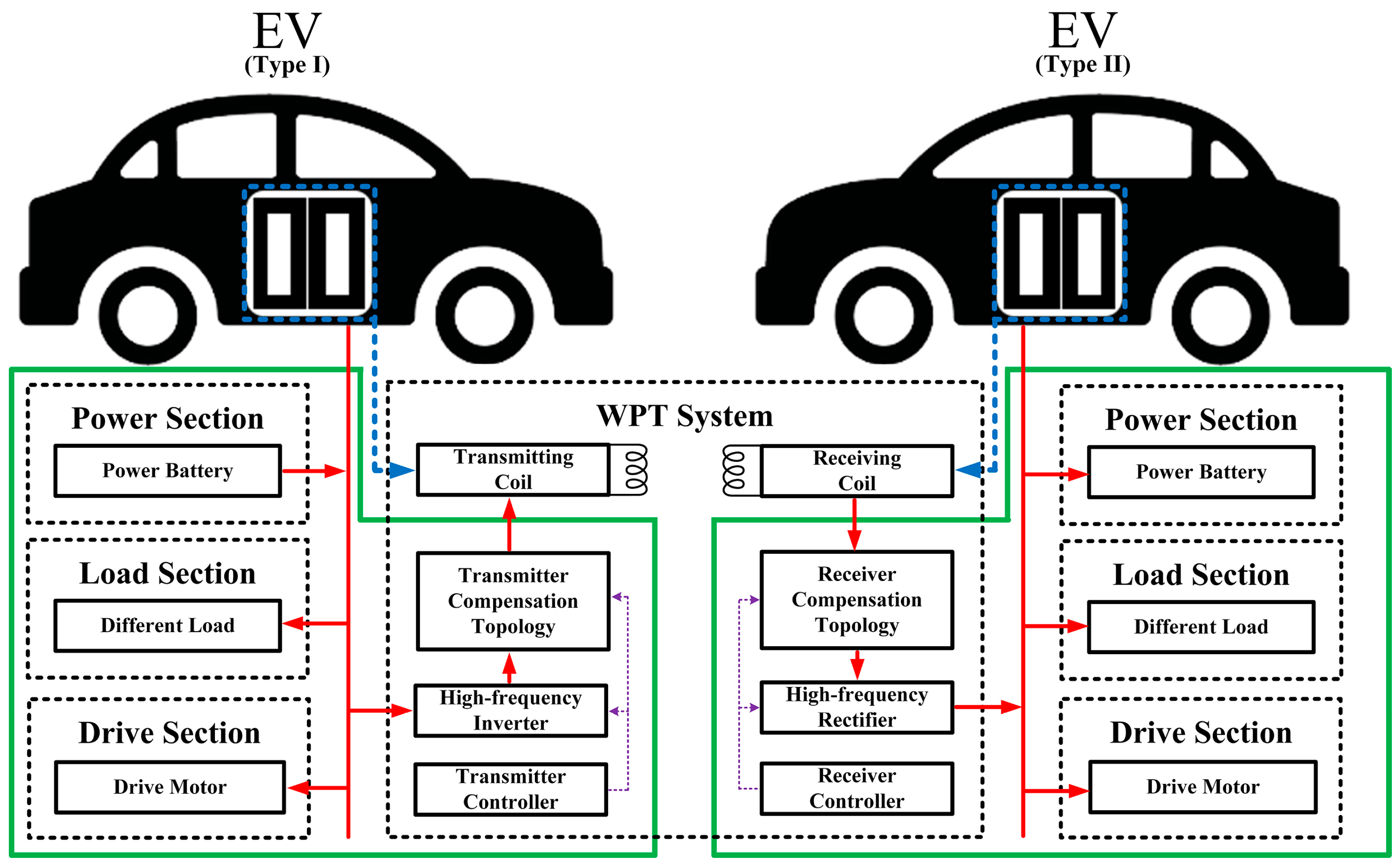
A general framework for an EV WPT system is shown in
Figure 1. The system comprises three components: the power section, the load section, and the drive section. The type I EV transmits electric energy to the type II EV through the WPT system. The high-frequency inverter inverts DC into high-frequency AC and the transmitter compensation topology reduces the reactive power of the transmitter circuit. The transmitter coil and receiver coil realize the conversion of electric and magnetic energy and, thus, the wireless transmission of energy. The receiver compensation topology reduces the reactive power of the receiver circuit. The AC is rectified into DC by the high-frequency rectification circuit at the receiver and then transmitted into the DC network of the type II EV. The transmitter controller and receiver controller issue control signals to regulate the WPT process.
Different from the WPT of electric vehicles in urban roads or parking lots, the WPT technology for EVs proposed in this paper seeks to realize wireless charging between EVs in desolate environments. In such conditions, the output characteristics of the compensation topology and the anti-misalignment and anti-deflection performance of the coupling coils are more demanding. For the compensation topology, as the working conditions of the electric vehicle are dynamically adjusted according to the environment, the system should still achieve constant voltage or constant current output when the coil mutual inductance and system load change. For the coupling coil, when the wireless charging of EVs is carried out in a desolate environment with uneven ground, the coupling coils can still maintain a high mutual inductance and the variation of mutual inductance is small when misalignment and deflection occur between the coupling coils at the transmitter and receiver ends. Based on the above analysis, compensation topologies with better adaptability and coupling structures with stronger anti-misalignment and anti-deflection performance are essential. The above two aspects are studied in the following parts of this paper.
The compensation circuit can reduce the reactive power of the EV WPT system, weaken the sensitivity of the system to changes in the coupling coefficient, load, and other parameters, and improve the transmission capacity of the system. According to the application scenario of the WPT system for EVs, in order to improve the adaptability of the compensation circuit, the compensation circuit should meet the following requirements as much as possible in the process of structure selection and parameter matching.
- 1.
The system should achieve load-independent constant voltage/current output:
The receiver of the WPT system in an EV usually needs to charge the energy storage elements, such as power batteries. The load characteristics of such elements will change during the charging process. If an appropriate compensation circuit structure can be designed to realize load-independent constant voltage/constant current output, the charging process can be better controlled and the charging efficiency of the system improved.
- 2.
The transmitting coil should achieve load-independent constant current output:
The transmitting coil achieves load-independent constant current output, that is, the current of the transmitting coil will not change with a change in the reflection impedance of the receiver, which can prevent excessive currents in the transmitting coil from causing damage to the transmitting coil when the receiver is open. In addition, in order to improve the ability of the EV WPT system to achieve one-to-many transmission, when the transmitting coil charges multiple receiving coils at the same time, under the condition that the transmitting coil realizes load-independent constant current output, the system input at the receiving end can be regarded as multiple constant voltage sources that do not affect each other.
- 3.
The input impedance should meet the zero phase angle (ZPA) condition:
The input impedance can meet the zero phase angle (ZPA) condition. Due to the large gap between the transmitting coil and the receiving coil, the leakage inductance of the coupling device is large, the reactive power input at the transmitting end is large, and the system efficiency is reduced during the operation of the WPT system in the EVs. Therefore, it is necessary to design a suitable compensation circuit such that the input voltage and input current of the transmitter remain in phase and the input impedance of the system is pure resistance, that is, the input impedance meets the ZPA condition and the reactive power of the system is reduced.
- 4.
The number of compensating devices should be as small as possible:
In the actual operation process of a WPT system on EVs, the compensation devices are not ideal devices, and there are parasitic resistors in the compensation inductor and capacitor. The higher the number of compensation devices, the greater the system loss and the lower the efficiency. Therefore, under the same conditions, the compensation circuit structure with the least number of compensation devices should be selected to reduce the system loss, thus improving system efficiency.
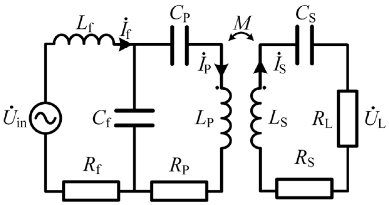
As for the LCC/S compensation topology, the current of the transmitter and the output voltage of the receiver are independent of the load resistance under the ZPA condition [
16,
17].
Figure 2 briefly presents the LCC/S structure, where
Uin is the input high-frequency AC voltage generated by the inverter;
Lf,
Cf, and
CP are the series compensating inductor, parallel compensating capacitor, and series compensating capacitor, respectively, which comprise the symmetric T-type network;
CS is a secondary series compensating capacitor;
L1,
L2, and
M are the primary self-inductance, secondary self-inductance, and mutual inductance of the coupling coils, respectively; and
RL is the equivalent load resistance of the receiver circuit.
Based on Kirchhoff’s voltage and current laws (KVL and KCL), circuit parameters for the LCC/S compensation topology can be developed.
In order to satisfy the zero phase angle (ZPA) condition, the resonant conditions of the LCC/S structure are designed as follows:
Ignoring the parasitic parameters of inductance and capacitance, the output voltage and power of the system can be expressed as follows:
According to the above formula, the system output is mainly related to the mutual inductance of the coupling coils and the equivalent load resistance of the receiver circuit. Therefore, it is important to design a suitable coupling structure for the EVs in order to reduce the mutual inductance variation when wirelessly charging in desolate places.
3. Design of Coupling Structure
The spatial motion of the coils in the process of WPT of the EVs mainly includes two types: misalignment and deflection.
Misalignment mainly includes two kinds: axial and radial misalignment. Axial misalignment is mainly due to the relative distance changing during the charging process of the EVs, which causes misalignment movement between the transmitting coil and the receiving coil along the direction perpendicular to the coil plane. Meanwhile, radial misalignment is mainly due to a deviation in the forward speeds of the EVs in the charging process, misalignment of the parking position, and the height difference between the vehicles in the vehicle group, which causes misalignment movement along the coil plane between the transmitting coil and the receiving coil.
Deflection types mainly include flip and rotation. Flipping is mainly due to the lateral slope between EVs, which causes the angle between the transmitting coil plane and the receiving coil plane to flip. Rotation is mainly due to the difference in angle of rotation between the transmitting coil plane and the receiving coil plane, relative to the initial state, due to the slope of the ground along the forward direction between the EVs.
Considering the above analysis, combined with the actual application scenario of EVs, the design requirements for the coupling coil can be summarized as follows.
- 1.
The coupling coil has a certain resistance to combined spatial motion:
Considering the terrain changes when the EVs are parked or moving, it is difficult to achieve alignment between the transmitting and receiving coils. Therefore, it is necessary to consider the combination of multiple spatial motion modes of the coil when designing the coupling coil.
- 2.
The size of the coupling coil should be limited:
The design size of the coupling coil should be limited according to the size of the EVs and the required transmission distance requirements.
- 3.
Electromagnetic shielding and electromagnetic compatibility should be considered:
The electromagnetic radiation generated during the use of the WPT device will affect the communication between EVs and the safety of surrounding personnel. Therefore, it is necessary to design electromagnetic shielding devices to weaken the influence of relevant electromagnetic radiation.
- 4.
The manufacturing cost of the WPT system should be considered:
In the case of the same or similar performance of the coupling coil, a coil optimization scheme with a smaller total number of turns should be selected.
3.1. Parameter Optimization
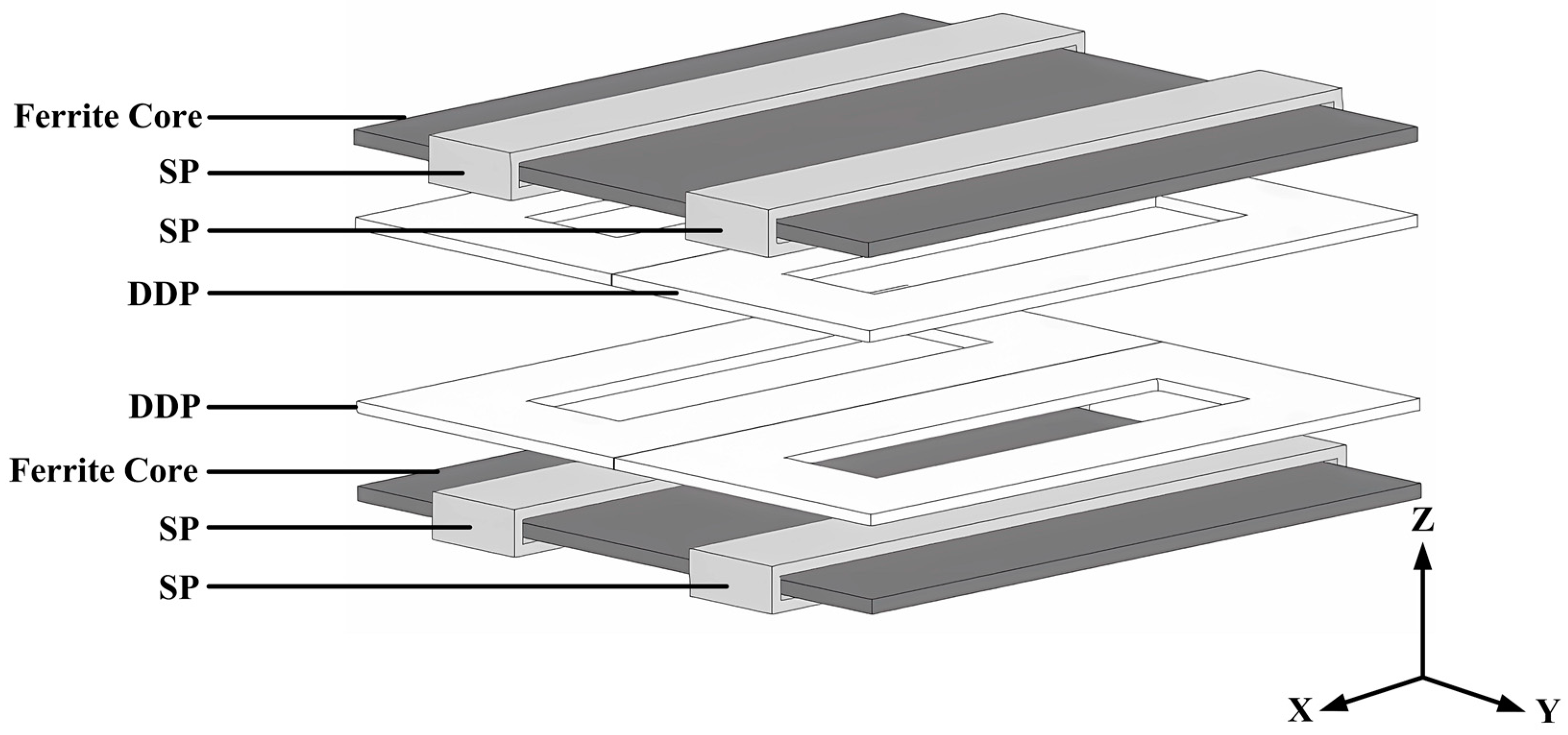
The solenoid pad (SP) and the double-D Pad (DDP) are two common planar coupling structures, which present anti-misalignment and anti-deflection performance in certain directions, respectively. In order to realize the complementary advantages of SP and DDP coupling structures and to design a coupling structure that satisfies the demands of EV wireless charging in desolate places, an SP-DDP coupling structure is proposed in this paper, which is shown in
Figure 3.
In order to improve the anti-misalignment and anti-deflection performance of the SP-DDP coupling structure, an inverse connection between the SP and the DDP at the transmitter and a forward connection between the SP and the DDP at the receiver are adopted. The circuit equivalent model is shown in
Figure 4.
In the figure,
LS1 and
LS2 are the self-inductance of the SP at the transmitter and the receiver, respectively;
LD1 is the self-inductance of the DDP at the transmitter and
LD2 is the self-inductance of the DDP at the receiver;
MS1D1 is the mutual inductance between the SP and the DDP at the transmitter;
MS2D2 is the mutual inductance between the SP and the DDP at the receiver;
MS1S2 and
MD1D2 are the mutual inductance between the SPs and DDPs at the transmitter and the receiver, respectively;
MS1D2 is the mutual inductance between the transmitter SP and the receiver DDP;
MD1S2 is the mutual inductance between the transmitter DDP and the receiver SP;
L1 and
L2 are the self-inductance of the transmitter coil and the receiver coil, respectively; and
M is the mutual inductance of the SP-DDP coupling structure. The formulas for
L1,
L2, and
M are provided below.
The coupling coil in an EV WPT system has strict requirements in terms of coil size, mutual inductance, and transmission distance, which greatly increases the difficulty of parameter optimization of the coupling coil. For the proposed SP-DDP coupling structure, this paper summarizes a set of parameters used in the optimization process. In order for the optimized coil to meet the relevant indices of the EV WPT system, the parameter optimization process included three parts:
Defining the limiting conditions and optimization parameters;
Finite element simulation and evaluation of the coil;
Electromagnetic shielding design.
3.1.1. Defining the Limiting Conditions and Optimization Parameters
In the finite element simulation experiment, 0.05 mm × 1000 strands of Litz wire with a diameter of 2.4 mm and a maximum current of 10 A were selected. The length, width, and height of the ferrite were 200 mm, 200 mm, and 3 mm, respectively. According to the demand of the WPT system studied in this paper, the self-inductance of the coupling structure must exceed 200 μH.
The number of coils has a great influence on the performance of the coupling coil. Therefore, the number of SPs and DDPs in the transmitter and the receiver were selected as optimization objects. The number of transmitter SPs, receiver SPs, transmitter DDPs, and receiver DDPs are represented by NS1, NS2, ND1, and ND2, respectively.
3.1.2. Finite Element Simulation and Evaluation of the Coil
Due to the limiting conditions of the WPT system, the number of coil turns should be less than 20. According to a previous experiment, the mutual inductance of the proposed SP-DDP coupling structure changed significantly with misalignment along the Y-axis. The simulation results indicated that when the number of turns of SP and DDP increased from 1 to 20, the mutual inductance increased with an increase in the number of turns along the Y-axis and the variation range of mutual inductance decreased gradually. When the number of coils varied within the range of 12 to 14, the mutual inductance variation was smaller than that corresponding to all the other coil turns within 100 mm misalignment along the Y-axis.
The proposed SP-DDP coupling structure was optimized by magnetic field finite element analysis. A simulation experiment was carried out to limit the mutual inductance variation range to 20%, and the maximum distance of the coupling structure misalignment along the
X- and
Y-axes within the mutual inductance variation range was solved. Under the condition of mutual inductance variation ranging less than 20%, the maximum misalignment distance of the SP-DDP coupling structure along the
X-axis was 180 mm and the minimum was 150 mm; meanwhile, the maximum value of the misalignment distance along the
Y-axis was 120 mm and the minimum value was 40 mm. Considering the maximum misalignment distance of the SP-DDP coupling structure along the
X- and
Y-axes, the maximum misalignment distance along the
X-axis was set to 160 mm and the maximum misalignment distance along the
Y-axis was set to 120 mm, and the total number of turns of the coil was minimized. The number of transmitter SPs, transmitter DDPs, receiver SPs, and receiver DDPs were obtained as 12, 14, 12, and 12, respectively. The optimized structure parameters are given in
Table 1.
3.1.3. Electromagnetic Shielding Design
The coupling structure transmits energy through a magnetic field coupling, which inevitably produces magnetic leakage and electromagnetic radiation. There are a large number of ferromagnetic structures in EVs, and wireless communication is required between EVs during wireless charging. Electromagnetic radiation will affect the communication between EVs and the safety of people in their vicinity. Therefore, it is necessary to design electromagnetic shielding devices to weaken the related electromagnetic radiation effects.
Common electromagnetic shielding methods for coupling coils include magnetic metal shielding and non-magnetic metal shielding. Magnetic metal shielding uses the characteristics of low magnetic resistance of magnetic metal materials, such that a large amount of the magnetic flux flows into the magnetic metal materials and, because of the large magnetic resistance, almost no magnetic flux inflow is observed in the shielding area, thus facilitating electromagnetic shielding. A non-magnetic metal shield achieves electromagnetic shielding by generating an induced electromotive force and eddy current inside it to weaken the magnetic field entering the shield area. Magnetic metal shielding can enhance the magnetic field in the coupling region but typically has a higher cost. Non-magnetic metal shielding is less costly but weakens the magnetic field in the coupling region.
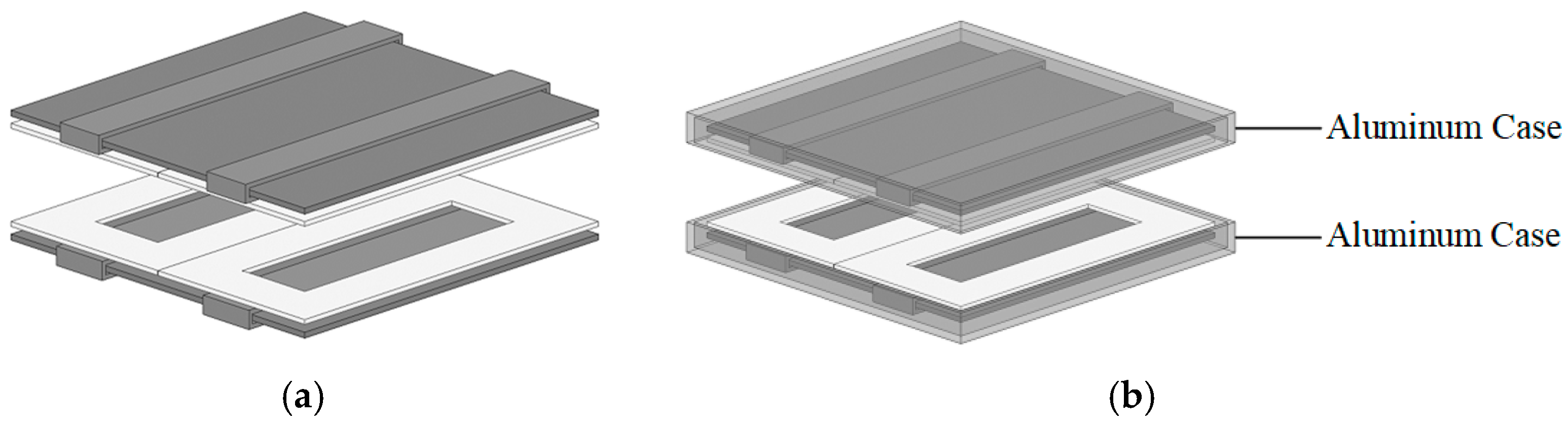
As a non-magnetic metal shielding material, aluminum has the advantages of light weight, high conductivity, and low cost. Therefore, a 1 mm-thick aluminum case was used as the electromagnetic shielding device for the coupling structure. The SP-DDP coupling structures with and without the aluminum case shielding are shown in
Figure 5.
A finite element simulation of the SP-DDP coupling structure before and after including the aluminum electromagnetic shielding was carried out, and the simulation results are shown in
Table 2. According to the simulation results, the performance of the coupling structure was not significantly changed before and after the aluminum plate was applied. However, the self-inductance and mutual inductance of the coil decreased, and the weight of the coupling structure increased slightly.
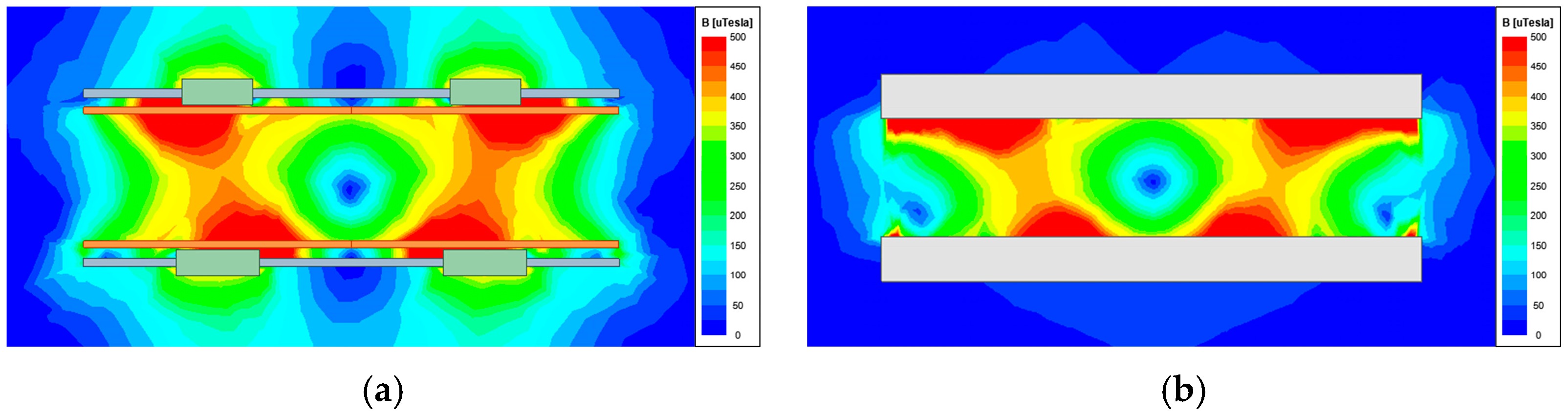
By analyzing the magnetic field distribution cloud diagram of the SP-DDP coupling structure with and without the aluminum case shielding, as shown in
Figure 6, the aluminum case was observed to shield a large amount of magnetic flux: the magnetic flux at the back of the transmitting coil and receiving coil was significantly reduced, indicating an outstanding shielding effect.
3.2. Anti-Misalignment and Anti-Deflection Performance
The movement of the SP-DDP coupling structure in space mainly includes two aspects: misalignment along the X-, Y-, and Z-axes and deflection around the X-, Y-, and Z-axes. The variation tendencies of the magnetic field and mutual inductance when misalignment and deflection occurred between the transmitter and receiver were analyzed, respectively.
Misalignment and mutual inductance changes in the SP-DDP coupling structure are depicted in
Figure 7. The SP-DDP coupling structure has the strongest anti-misalignment performance along the
X-axis, the second-best anti-misalignment performance along the
Y-axis, and the weakest anti-misalignment performance along the
Z-axis. In particular, when the misalignment distance was less than 160 mm along the
X-axis, 120 mm along the
Y-axis, and 100 mm along the
Z-axis, the variation amplitude of mutual inductance was less than 20%.
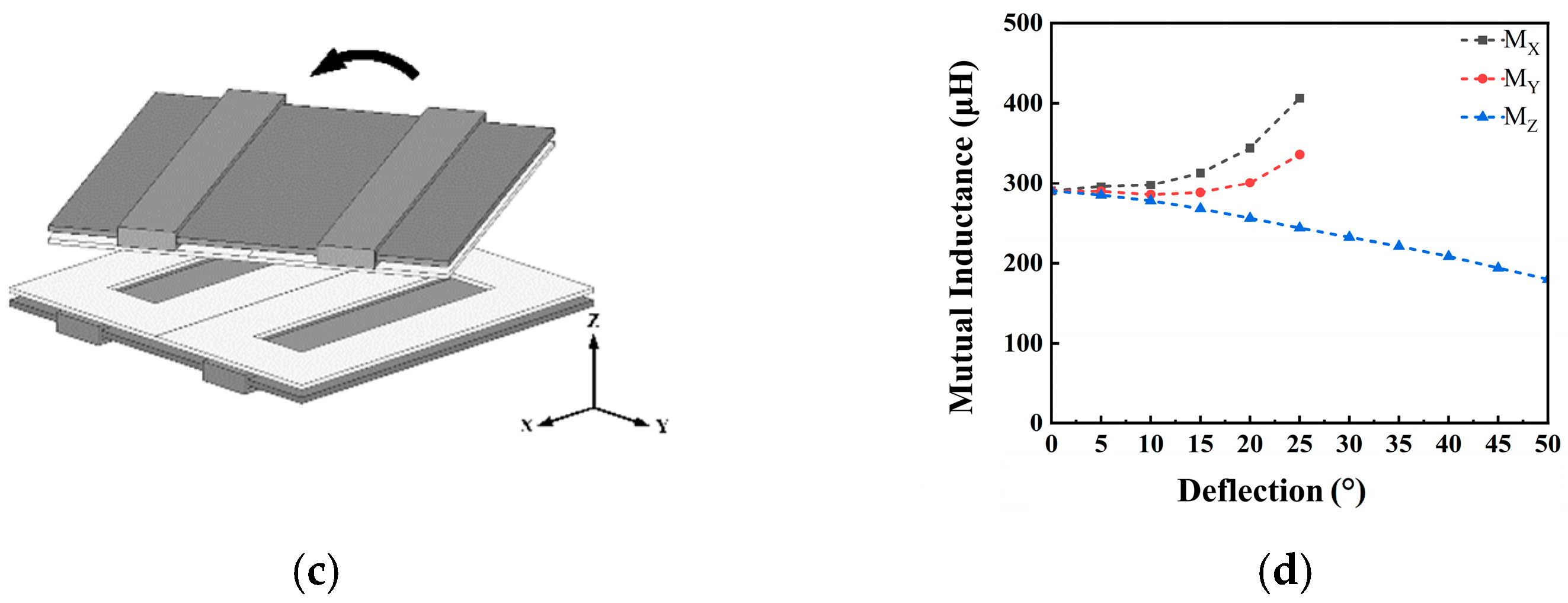
The deflection and mutual inductance change of the SP-DDP coupling structure are shown in
Figure 8. The SP-DDP coupling structure presented the strongest anti-deflection performance around the
Y-axis, the second-best anti-misalignment performance around the
Z-axis, and the weakest anti-misalignment performance around the
X-axis. When the deflection degree was less than 20° around the
X-axis, 25° around the
Y-axis, and 30° around the
Z-axis, the variation amplitude of mutual inductance was less than 20%.
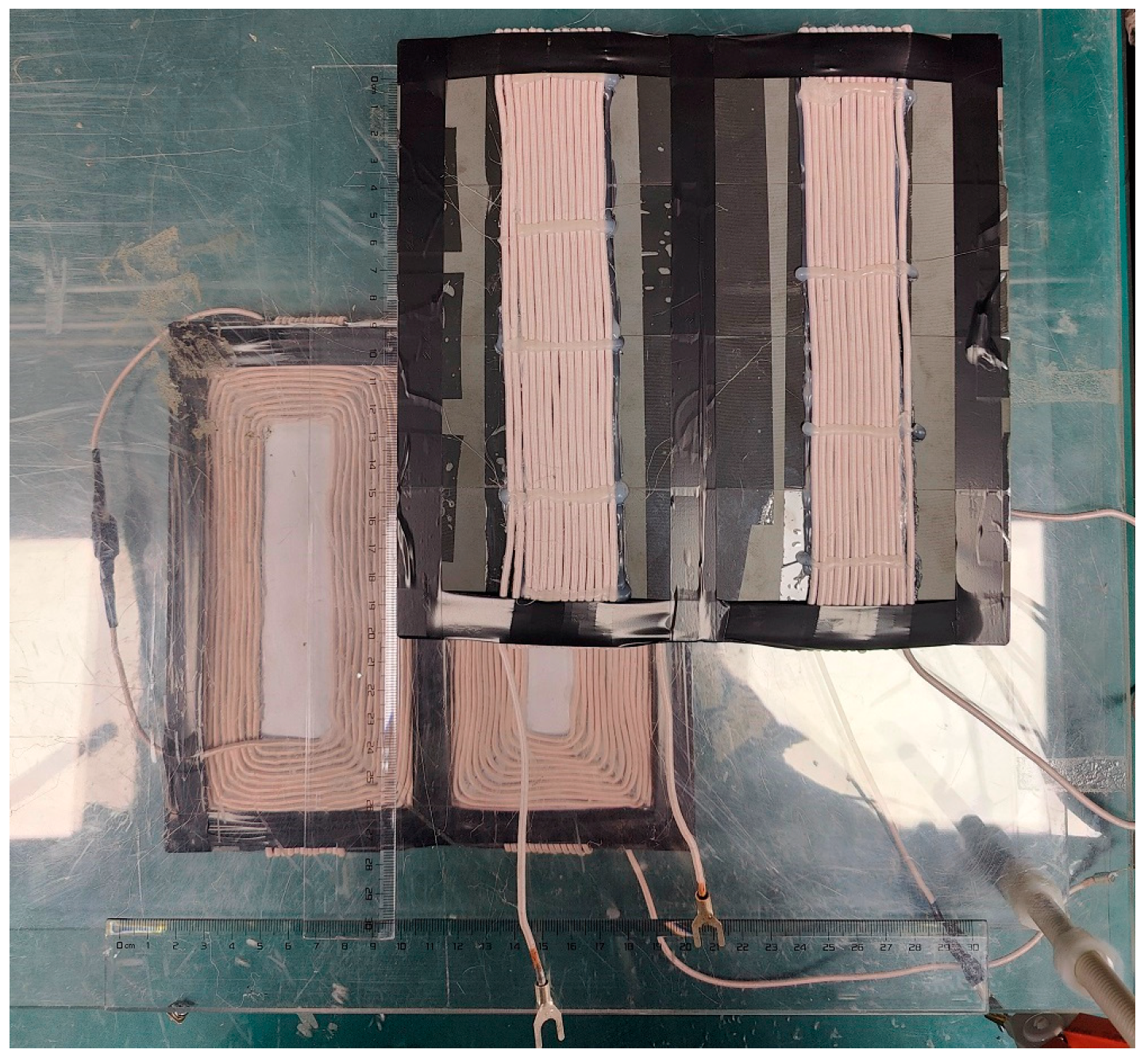
3.3. Experiment of Prototype
The SP-DDP coupling structure was fabricated using Litz wire, and the parameters of the coupling structure were consistent with the simulation parameters given in
Table 1. The experimental prototype of the SP-DDP coupling structure is shown in
Figure 9.
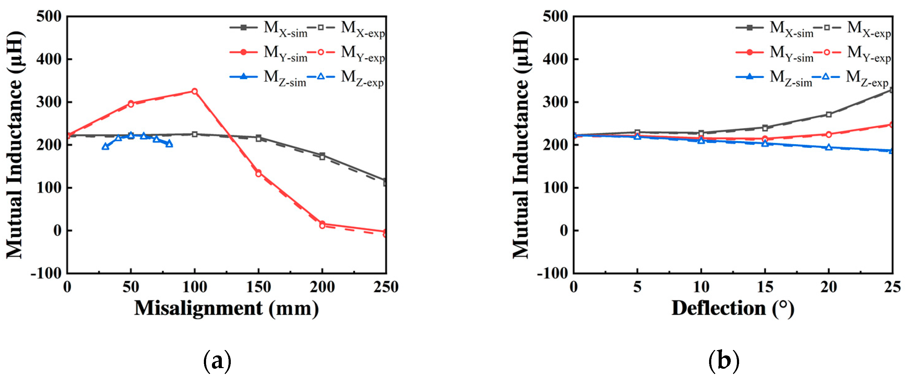
In the experiment, the simulated coupling coil was shifted along the X- and Y-axes, and the LCR digital bridge was used to measure the self-inductance and mutual inductance of the coupling coil.
A comparison between the simulation results and the experimental results is shown in
Figure 10.
MX-sim,
MY-sim, and
MZ-sim are the simulation mutual inductance of misalignment along the
X-,
Y-, and
Z-axes as well as the deflection around the
X-,
Y-, and
Z-axes, respectively;
MX-exp,
MY-exp, and
MZ- exp are the experimental mutual inductance of misalignment along the
X-,
Y-, and
Z-axes as well as the deflection around the
X-,
Y-, and
Z-axes, respectively.
The experimental results demonstrated that, under the condition that the transmission distance between the transmitting coil and the receiving coil is 50 mm and the coil is in a positive position, the self-inductance of the transmitting coil is 312.26 μH, the internal resistance is 0.23 Ω, the self-inductance of the receiving coil is 274.53 μH, and the internal resistance is 0.21 Ω. The mutual inductance of the coils is 222.49 μH. The discrepancy between the simulation and experimental values for the mutual inductance of the coupling structure was mainly caused by the tightness degree and shape deviation of coil winding when developing the coupling structure. The measuring instrument is also an important source of error. The experimental results for the SP-DDP coupling structure verify that the proposed coupling structure has excellent anti-deflection and anti-deflection performance. Under the proposed experimental conditions, the output efficiency of the system was 92.65% and the output power was maintained at 192.02 W.


