Abstract
In the mid-low speed Maglev train, the levitation force produced by end electromagnets is influenced by the train speed due to the eddy current effect, especially the front-end electromagnets at high speed. In this paper, the eddy current effect of front-end electromagnets is calculated by an analytical method, which is validated by the Finite Element method (FEM). To compensate a decrease of levitation force, two improved structures of end electromagnet modules are designed and compared. One is the permanent magnet compensation structure, designed by inserting a piece of permanent magnet (PM), and called the PM hybrid structure, and the other is an additional electromagnet compensation structure, which adopts five electromagnets, and called the five-coil structure. In terms of comparison, the five-coil structure can not only produce a high enough levitation force, but can also be easily manufactured. Its effectiveness is verified by the prototype application.
1. Introduction
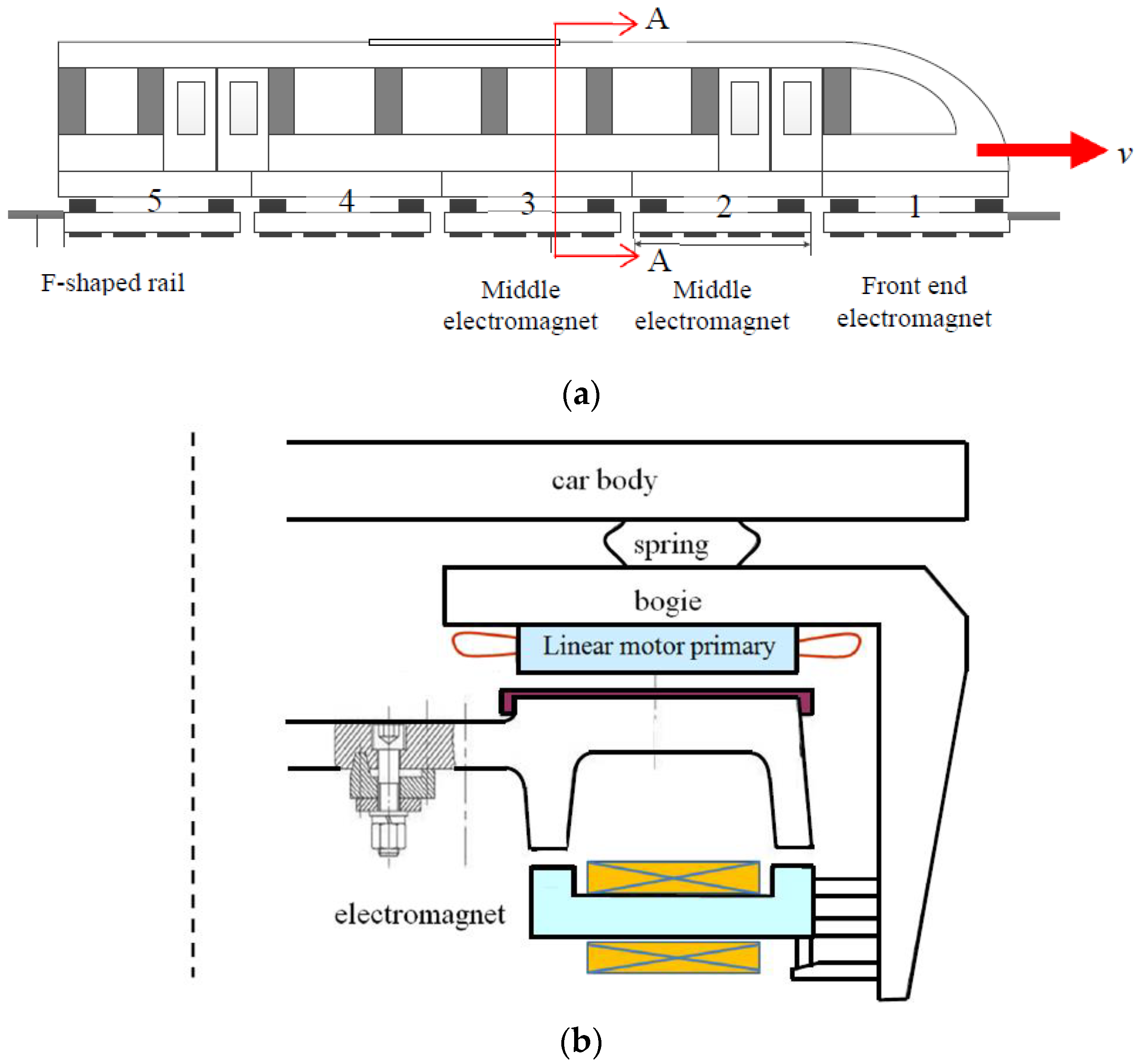
The mid-low speed Maglev train adopts electromagnets to provide levitation force [1,2]. In each train carriage, there are ten electromagnet modules, which are uniformly distributed on two sides and directly face the F-shaped rail. Figure 1a shows a lateral view of five electromagnet modules in one train carriage, and Figure 1b shows the cross section of the train.
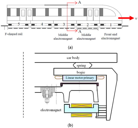
Figure 1.
Levitation system diagram of mid-low speed Maglev train: (a) The lateral view of five electromagnet modules in one train carriage; (b) The cross section of the train (A-A).
When the electromagnets are supplied with DC excitation currents, an attractive normal force, also called levitation force, is produced between the electromagnets and the F-shaped rail. With this levitation force, the train carriage is attractive to the rail and this makes the train levitate at a fixed air gap length, normally 9–12 mm. To each electromagnet at the fixed levitation air gap length, the levitation force is mainly decided by the DC excitation current. In addition, it is also relative to the train speed. Since the F-shaped rail is made of solid iron, an eddy current is induced during the train’s operation, alongside the levitation force. Apparently, the eddy current can decrease the levitation force of the end electromagnets.
Normally, the mid-low speed Maglev train operates at around 100 km/h [1,2], so the decrease in levitation force produced by the end electromagnet module is not so big, and all electromagnet modules have the same structure. However, when the train operates at high speed (≥160 km/h), the influence becomes apparent. It is critical to the operation of the levitation system and the design of the electromagnets. The calculation of levitation force has been researched by many researchers with different methods to consider the influence of speed [3,4,5,6,7]. Further to the levitation force, the tangential force produced during motion is also investigated [8], which adds additional braking force to the linear induction motor [9]. Moreover, the coupling effect of levitation and the guidance systems are researched [10], and the high-precision analytical model and high-performance control method are investigated [11,12]. Other than the analytical and control methods, research on the hybrid excitation structure is vital in order to improve the suspension capability of the Maglev train, which can depend on the permanent magnet (PM) and electrical excitation [13,14,15,16,17], or HTS coil excitation and electrical excitation [18]. The HTS electromagnet is also focused on [19].
Levitation force is deeply influenced by the eddy current effect. As imagined, levitation force is decreased due to eddy current. This influence becomes more serious when the speed of the Maglev train increases, such as from 100 km/h to 200 km/h [20]. In order to keep the levitation force constant, the excitation currents of the end electromagnets become bigger. Apparently, the biggest eddy current occurs at the entrance end, which is normally called the front end. That is to say, the excitation currents of front-end electromagnets need to be much improved. In order to lower the levitation excitation current, the normal method is to adopt a hybrid excitation structure. The disadvantages are that it is difficult to control, has low reliability, low mechanical strength and so on. They are still in the progress of research and have not been applied to the actual train yet.
In this paper, levitation force is first calculated, considering the eddy current effect, by an analytical method, and then the influence of high speed is analyzed, which is validated by the FEM method. After that, the PM compensation structure (PM hybrid structure) and the additional electromagnet compensation structure (five-coil structure) of the end electromagnet modules are proposed in order to keep levitation force as constant as possible. Finally, the five-coil structure is adopted and validated.
2. Analytical Method of Levitation Force
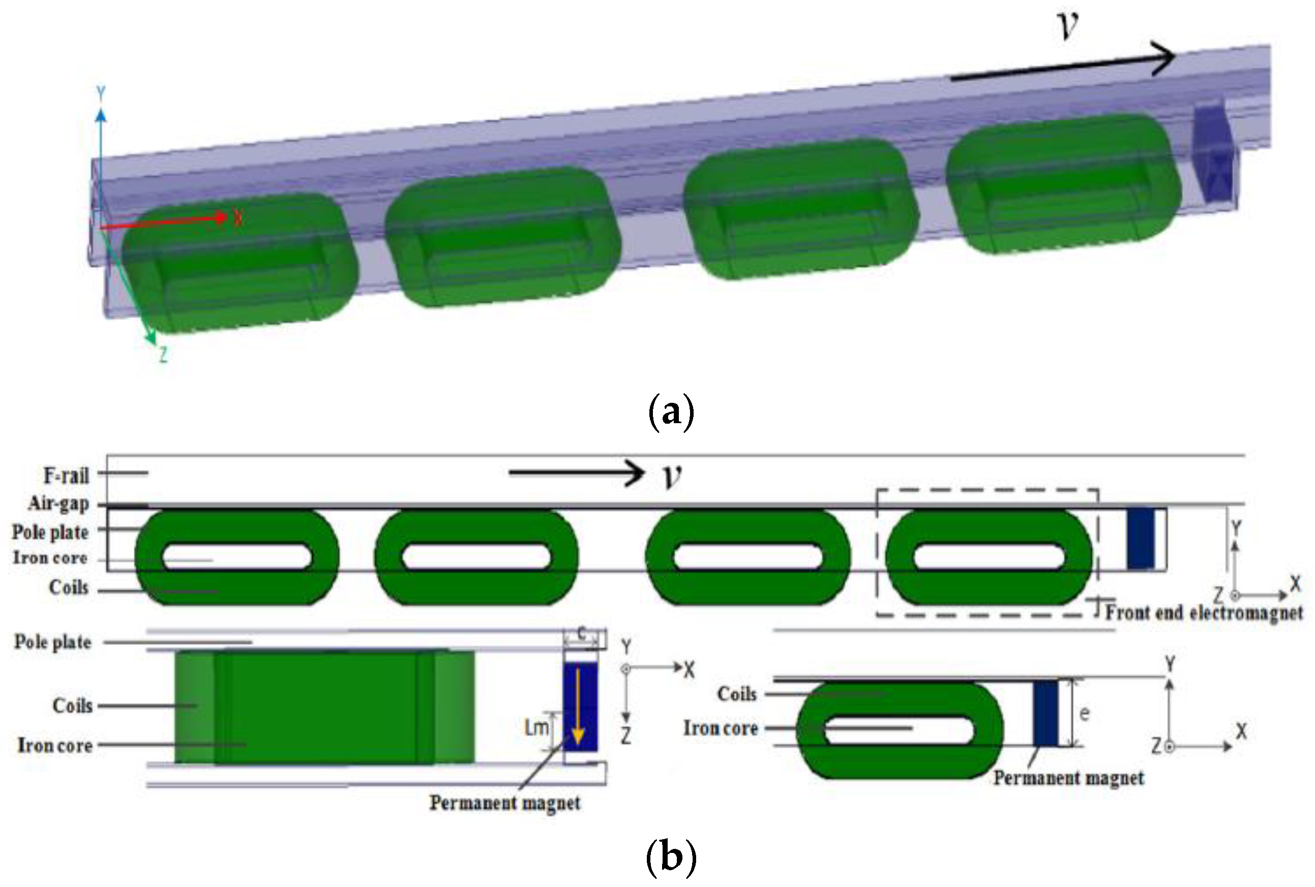
Figure 2 shows a 3D diagram of one electromagnet module of the No. 5 vehicle of the Changsha Maglev line. The electromagnet module is composed of two pole plates, four coils and four bottom plates, which face on to a solid iron core F-shaped rail. That is to say, there are four identical electromagnets in one module. The four excitation coils are made of aluminum due to the design requirement for light-weight materials. The main geometry parameters and materials are listed in Table 1.
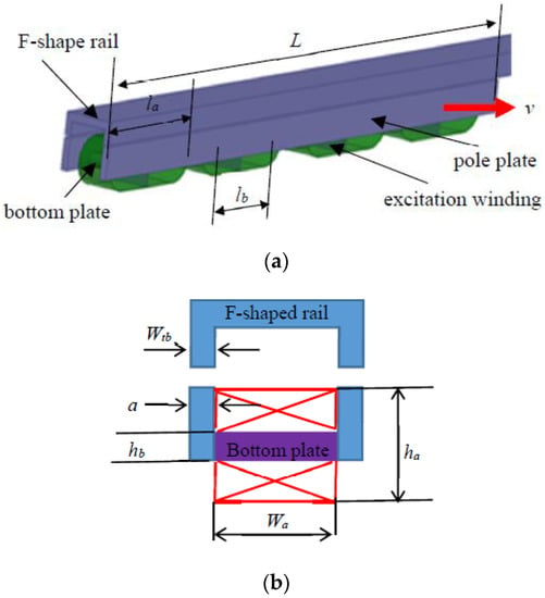
Figure 2.
3D model of one electromagnet module: (a) 3D diagram; (b) geometry parameter diagram.

Table 1.
Main Geometry Parameters of Electromagnet module.
The levitation force can be calculated by the analytical method (AM). The analytical method can rapidly calculate the average levitation force, but the saturation of iron core and the difference among the four electromagnets cannot be considered.
With the AM, the levitation force calculation expression, considering eddy current effect, is as follows [7]:
where Fy0 is the levitation force under static conditions, By0 is the air gap flux density produced by DC excitation current, Cn, an are the coefficients, n is harmonic order,, L, a are the air gap, iron length and plate width, N is the turn number per excitation coil and I is the excitation DC current. The coefficients Cn and an are the function of speed v, the calculation methods of which are shown in Ref. [7].
With Equations (1)–(3), the levitation force can be calculated, shown in Table 2. As can be seen, the influence of speed becomes more and more apparent along with the increase of speed. When the speed increases to 160 km/h, the levitation force is only 71.2% of that of the static condition.
Table 2.
The Calculated Levitation Force by AM.
To maintain constant levitation force, the excitation current needs to be improved. As can be seen in Equations (1)–(3), the levitation force is directly proportional to the square of excitation the DC current, therefore the excitation DC current of 160 km/h operating velocity is 1.185 times that of the static levitation status. Since the analytical method simplifies the model, the calculation is bound to have certain errors; moreover, it only focuses on the average value. In order to verify the results of AM, the 3D FEM method is adopted, since it can calculate accurate levitation force under any conditions.
3. 3D FEM Model of Levitation Force
For the low-speed Maglev train, electromagnet modules are not continuously fixed, as shown in Figure 1a. The gap between two adjacent modules is 168 mm. Under the gap area, there exists small eddy current in the F-shaped rail, since flux density has some change. Under ideal conditions, all modules need to be included in the 3D FEM model to calculate the actual levitation force of each electromagnet module. However, this kind of FEM model is so big that a normal computer cannot be used. Therefore, the 3D FEM model needs to be simplified. As shown, although the eddy current is induced in the F-shaped rail under each gap area, the biggest eddy current occurs in the front-end electromagnet module, and its levitation force is different to the others. That is to say, the modules are divided into two kinds and can be analyzed by two models. First, model one only includes the front-end electromagnet module when calculating the levitation force of the front end. Second, model two includes both the front-end electromagnet module and one middle electromagnet module in calculating the levitation force of the middle one.
3.1. Model One: Front-End Electromagnet Module
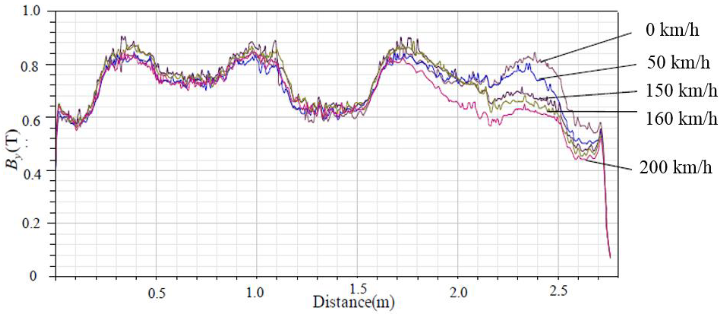
The FEM model of the front-end electromagnet module is erected, shown in Figure 3. The longer F-shaped rail is the stator, and the shorter electromagnet module is the mover. Based on this model, air gap flux density and levitation force are calculated. Figure 3 shows the distributions of air gap flux density By at the speed 0 km/h, 50 km/h, 100 km/h, 160 km/h and 200 km/h during the whole length of the front-end electromagnet module. As shown in Figure 2a, the speed of the train is towards the right direction. As to the F-shaped rail, the left is the departed end, and the right is the front end.

Figure 3.
The distributions of air-gap flux density at different speeds over the whole length of the front-end electromagnet module.
As can be seen, at the front end, the air gap flux density of the front-end electromagnet module decreases with increase in eddy current, while that of the departed end is only slightly affected. Moreover, over the whole length, By is not constant. The high value is under the electromagnets, while the low value is under the gap between the two electromagnets. The levitation force at different speeds is obtained, listed in Table 3. Apparently, the results of FEM are slightly lower than that of the analytical method. The error is 0.3 kN at 200 km/h and 1.7 kN at 0 km/h. That is to say, the results of both methods are almost identical, especially at high speed.
Table 3.
Levitation Force of Electromagnet by FEM.
3.2. Model Two: Front End Electromagnet Module and One Middle Electromagnet Module
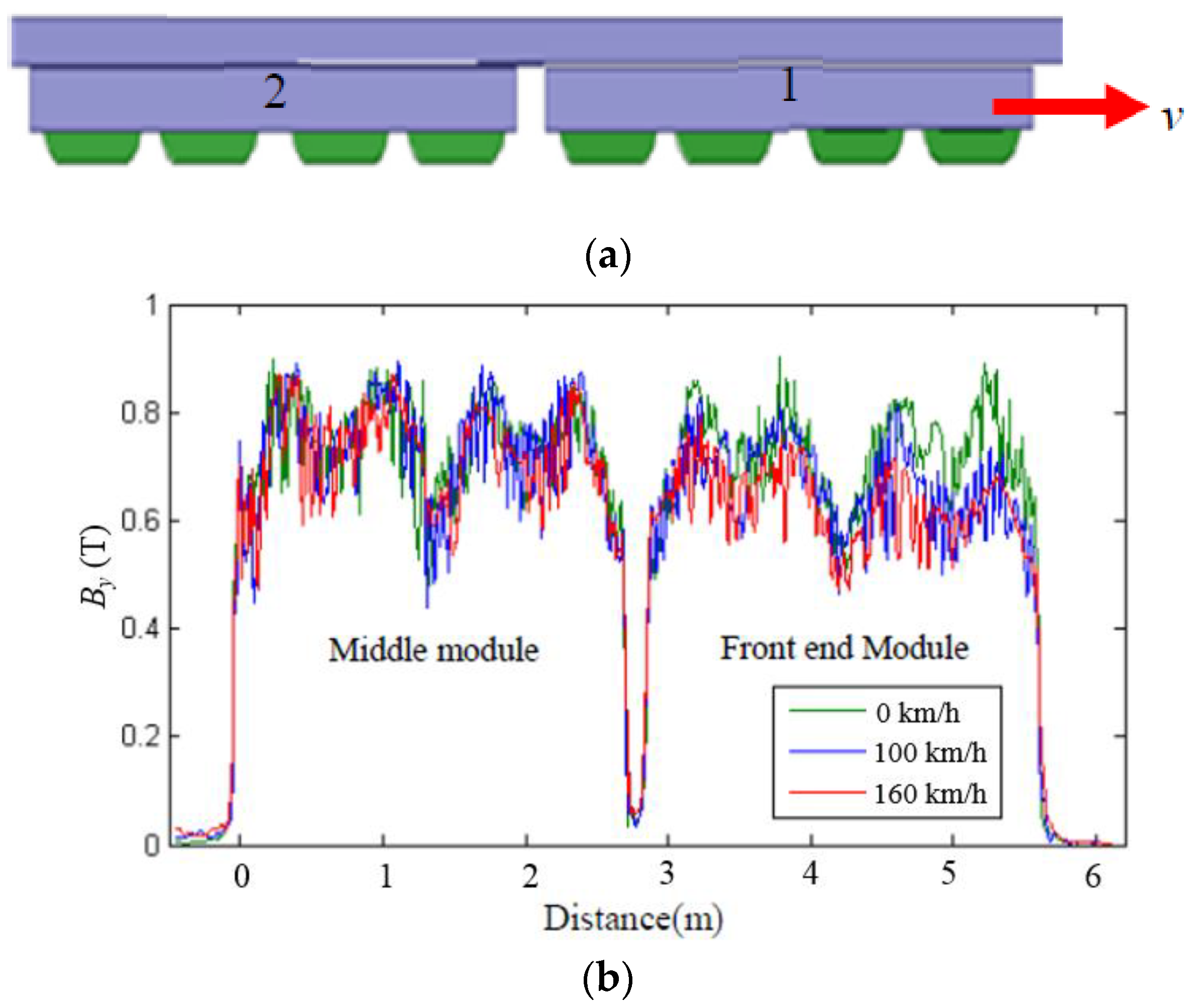
The former calculation is focused on the front-end electromagnet module, so that the levitation force of the middle electromagnet module cannot be investigated. Therefore, the 3D FEM model with front-end electromagnet and one middle electromagnet was built, shown in Figure 4a, which are No. 1 and No. 2 modules in Figure 1a.

Figure 4.
FEM model and air-gap flux density of two electromagnet modules at different speeds: (a) The FEM model of two electromagnet modules; (b) Air-gap flux density along with longitudinal direction.
With this model, the air gap flux density and levitation force of two electromagnet modules are calculated. Figure 4b shows the air gap flux density along with the longitudinal direction at speed 0 km/h, 100 km/h and 160 km/h. On the right is the front-end electromagnet, and on the left the middle electromagnet. Apparently, compared with the front-end electromagnet, the air gap flux density of the middle electromagnet is slightly affected. That is to say, the eddy current has influenced the levitation force of all electromagnets, but the front-end one has been influenced more. In this two modules model, the levitation force of the front-end electromagnet module and of the middle electromagnet model are obtained. Subtracting the levitation force from model one, the levitation force of the middle electromagnet module can be obtained. Assuming the middle electromagnet modules are the same, the total levitation force of all the middle electromagnet modules is obtained by multiplying by the number of electromagnet modules.
With model one and model two, the levitation force of the whole Maglev train can be calculated by adding that of the front-end electromagnet module with those of all the middle electromagnet modules.
3.3. Experimental Validation
The dynamic levitation force under high speed conditions cannot be directly measured. However, regarding the Maglev train, since the levitation force needs to be kept constant, excitation DC current needs to be adjusted according to speed. Therefore, the influence of speed on levitation force can be shown by the measured excitation DC current. Table 4 shows the measured excitation currents of front-end electromagnets and middle electromagnets when the speed v is 0 km/h and 87.5 km/h respectively.
Table 4.
Measured excitation current of electromagnets.
As can be seen, the excitation current of the front-end electromagnet increases from 34.02 A to 41.57 A when the train accelerates from 0 km/h to 87.5 km/h. The increase ratio is 1.22 times, which is bigger than for the analytical results. However, that of middle electromagnets changes from 32.76 A to 30.24 A. That is to say, the front-end one is the most seriously influenced, while the middle one is slightly influenced. Regarding the front-end electromagnet, temperature increases due to the enlarged excitation DC current, especially at high speed.
4. Improved Structures of End Electromagnet Module
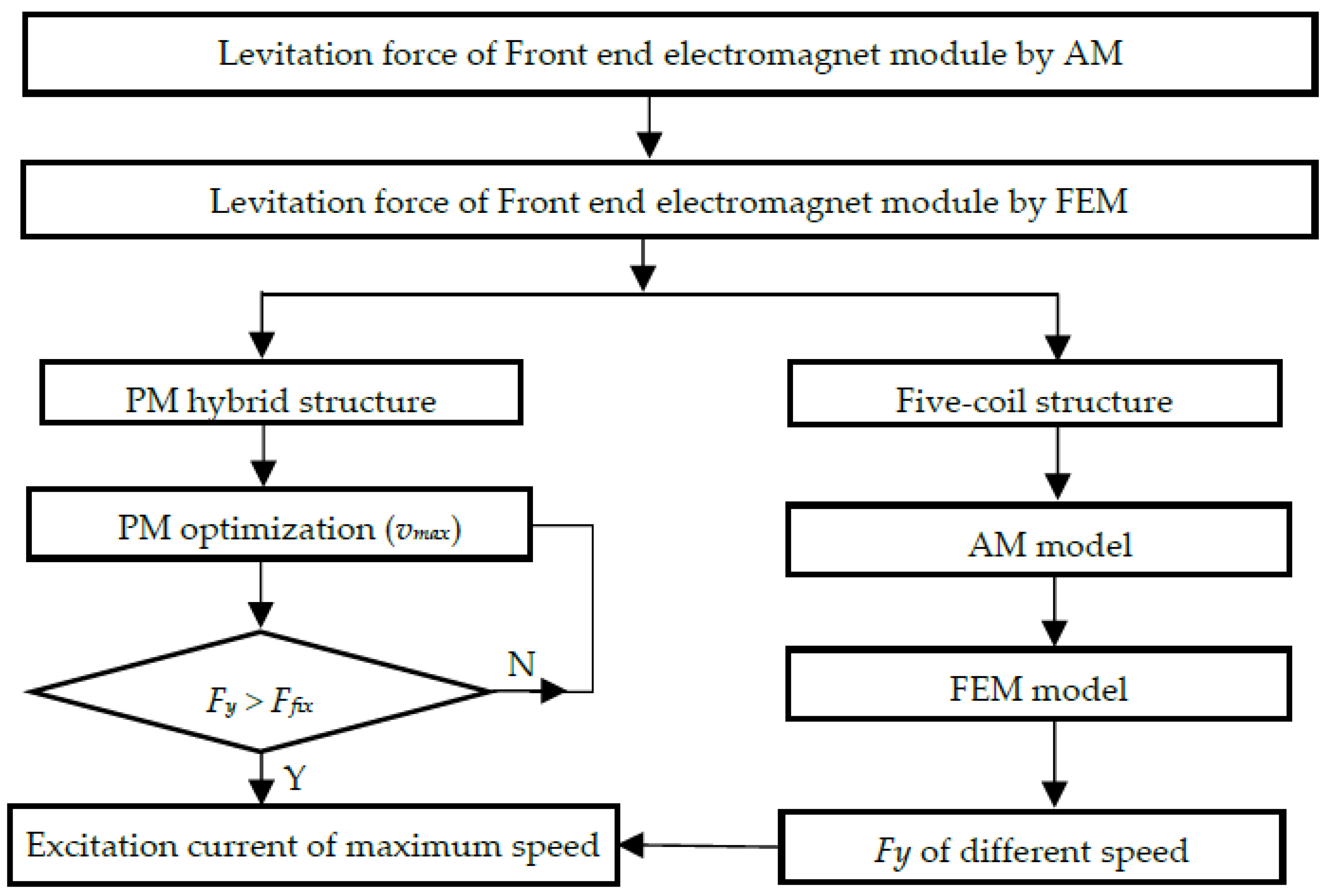
The front-end electromagnet module has high excitation current at high speed which makes the temperature increase, so that the end electromagnet module may overheat and burn down. In order to reduce the excitation current at high speed, two effective compensating methods can be adopted. One is a PM hybrid structure and the other is a five-coil structure, which can improve the excitation flux density. These two improved structures are not aimed at decreasing the eddy current of the rail, but at increasing the static levitation force, which makes the levitation force improve at high speed. This section aims at designing an effective end electromagnet module by following analysis, and the design flow chart is shown in Figure 5.
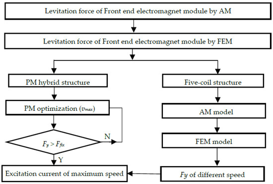
Figure 5.
The flow chart of improved structures.
4.1. PM Hybrid Structure
The PM hybrid structure inserts a permanent magnet between two pole plates in the front end of the electromagnet module. Viewing the magnetic field circuit, the electrical excitation and PM excitation are in parallel. The detailed position of the permanent magnet is shown in Figure 6a. Figure 6b shows the PM magnetization direction and dimensions diagram. The material of the permanent magnet is NdFeB35. According to the design flow chart shown in Figure 5, the dimension of the PM is designed when the levitation force of 160 km/h is more than the required value Ffix, 39 kN. The length Lm, height c and width e of the permanent magnet are 0.0702 m, 0.072 m and 0.135 m, respectively.
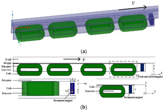
Figure 6.
Hybrid excitation structure: (a) 3D FEM; (b) the lateral view.
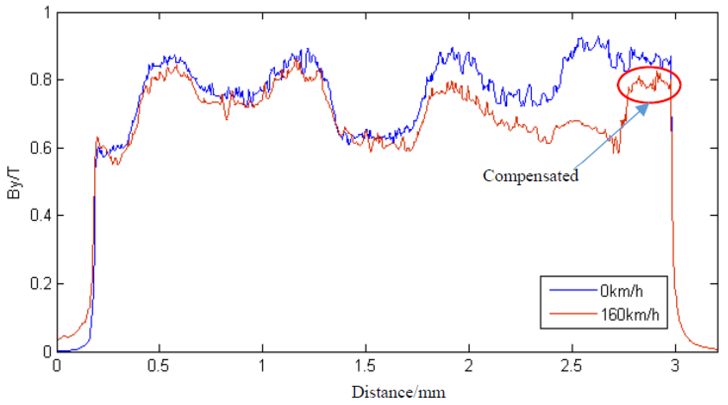
Based on the 3D FEM model, the air gap flux density is calculated at a speed of 0 km/h and at 160 km/h, shown in Figure 7. Apparently, although the air gap flux density is still lowered in the front-end electromagnet by the eddy current, the impact of the influence is effectively compensated, since the air gap flux density in the end is improved, due to the additional PM compared with the former traditional structure. In this application, the levitation force of maximum speed is most important, so that only this speed is investigated.
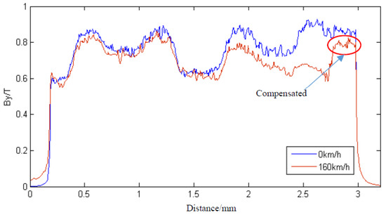
Figure 7.
Air-gap flux density of PM hybrid structure.
The calculated levitation forces are listed in Table 5. As can be seen, the levitation force of this PM hybrid structure increases to 39 kN at 160 km/h, which is very close to that of the traditional structure at 0 km/h. Apparently, the excitation DC current at high speed does not need to improve. Moreover, the excitation DC current at static levitation is lowered.
Table 5.
Levitation Force of PM hybrid structure.
In conclusion, the temperature of the front-end electromagnet module can be lowered during the whole operating time. However, reliability of the levitation system is affected by adding the PM since the electromagnets need to work outdoors in an open environment. The control method also becomes different when considering the levitation force contributed by the PM.
4.2. Five-Coil Structure
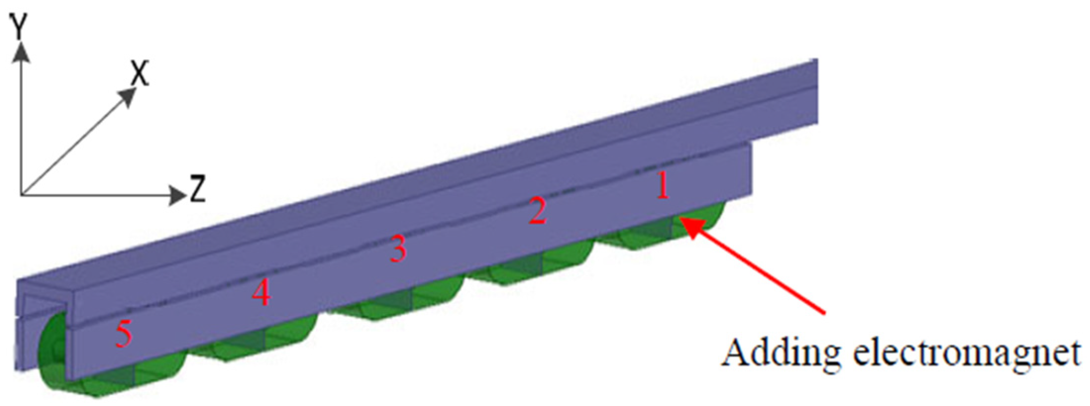
In order to avoid adopting the PM, another effective method is to add additional electromagnets in the front-end electromagnet module, to form what is called the five-coil structure. That is to say, the front-end electromagnet module has five electromagnets, so that the length of the front-end electromagnet module is enlarged from 2.72 m to 3.385 m, as shown in Figure 8. Compared with the PM hybrid structure, it is much heavier, but it is easily manufactured, since all the electromagnets are the same.
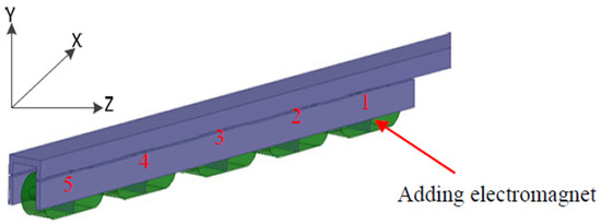
Figure 8.
3D FEM model of five-coil structure.
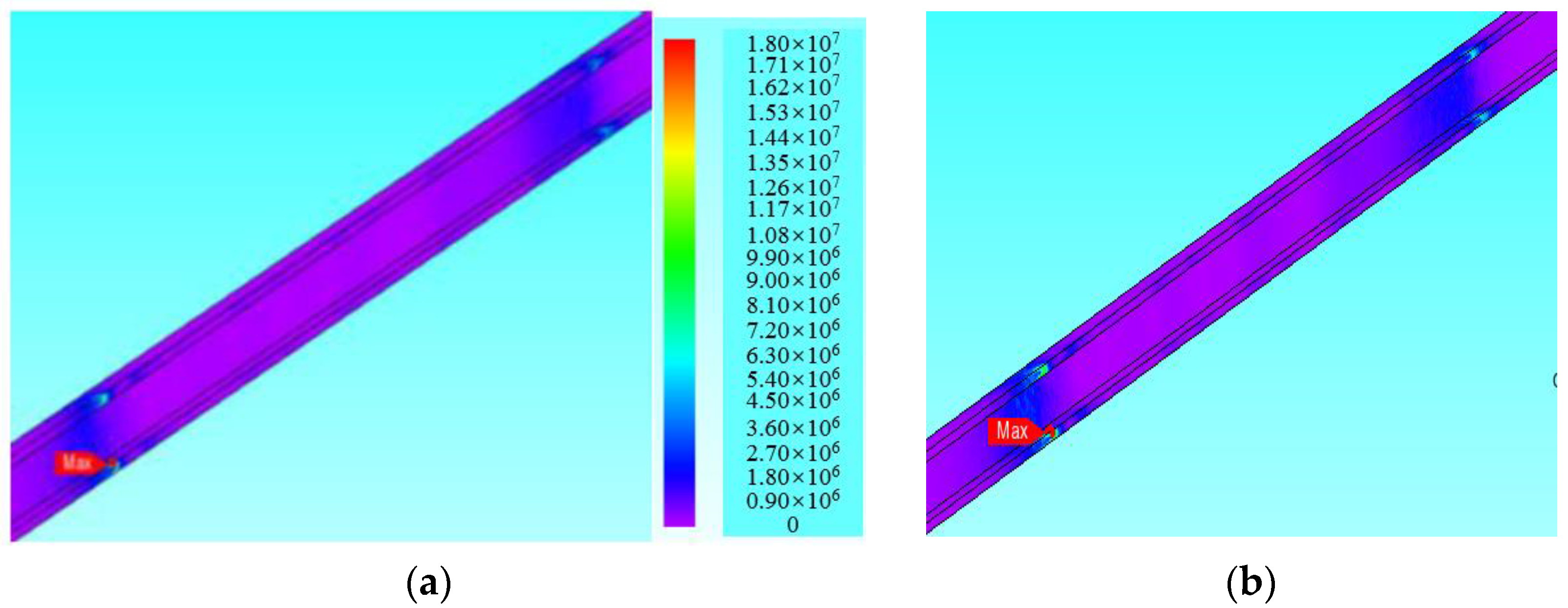
Under the same excitation current, the levitation forces at different speeds are calculated, shown in Table 6. The corresponding eddy current of the F-shaped rail is shown in Figure 9. Apparently, although the eddy current is increased, the levitation force can still reach 41.4 kN when speed is 160 km/h, which is more than that of the static traditional structure. At the same time, the static levitation force is much more than that of the traditional one.
Table 6.
Levitation Force of Five-coil Electromagnet Structure.

Figure 9.
The eddy current of F-shaped rail at different speed: (a) 100 km/h; (b) 160 km/h.
That is to say, the excitation DC current is lower during the whole operating time compared to the traditional structure, which has better compensating effect than the PM hybrid structure. Although the volume and mass of the end electromagnet module becomes big, reliability is not affected and manufacture is easy because all electromagnets are the same. To the traditional structure, two electromagnets are controlled by a control unit. To this five-coil structure, five electromagnets are still divided into two groups, therefore a control unit controls three electromagnets, but the control method is the same as that of the traditional one.
5. Prototype and Experiment
Both improved structures can effectively improve the levitation force of front-end electromagnet modules at high speed. The PM hybrid one lowers reliability and also makes installation difficult, so that it has still not had successful engineering application up till now. The five-coil one enlarges the length and mass of the electromagnet module, but does not change the control method and reliability. Considering its practicability, the latter one was selected as the end electromagnet module for a 160 km/h Maglev train. The prototype was then made and applied in an actual Maglev train.
5.1. Static Test Platform
Figure 10 shows the five-coil structure prototype and corresponding test platform, which has five electromagnets. The F-shaped rail is attached to the test base, and the electromagnet module is installed under the force bracket to keep the fixed air gap between electromagnets and the F-shaped rail. Four force transducers are fixed between the force bracket and test bed.
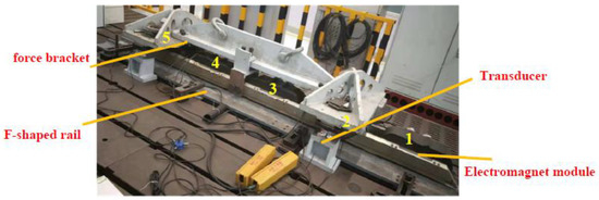
Figure 10.
The coil-compensated front-end electromagnet module and corresponding test platform.
When supplied with excitation DC current, the levitation force, called normal force, can be measured. Table 7 shows the measured results and predicted results, which are compared with that of the traditional structure under the same excitation current. It can be seen that the error between measured and calculated results is less than 5%, which is within the engineering tolerance limit. In addition, its levitation force is 10.4 kN higher than that of the traditional structure.
Table 7.
The Comparison of Levitation Force (kN).
5.2. Application Test
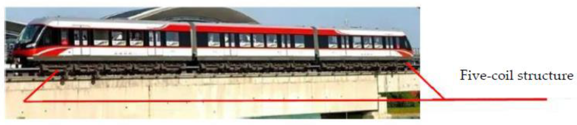
It has already been applied on the 160 km/h Maglev train, shown in Figure 11, which has successfully reached 160 km/h on the commercial Changsha line. In the end electromagnet module, the end three coils are in a series as a control unit, called point 1, and the other two are in a series as another control unit, called point 2. Although the levitation force cannot be directly measured for the Maglev train, the air gap length can be controlled for suspension operation. The operation validates that this five-coil structure is effective for the Maglev train at high speed.

Figure 11.
160 km/h Maglev train adopting five-coil structure as end electromagnet module.
6. Conclusions
The levitation force of front-end electromagnets in the Maglev train are affected by the eddy current in the F-shaped rail during the operation. An analytical method, considering the eddy current effect, was employed in this paper. With this method, the levitation forces of different speeds were investigated and compared with those of FEM. It was shown that the levitation force of the front-end electromagnet module decreases about 8.7 kN at a speed of 160 km/h. The effectiveness of the FEM model is validated by the static levitation force of the prototype.
Since the levitation force cannot be changed to keep the suspension stable, the DC excitation current needs to be improved, along with increase in train speed. In order to keep the levitation force without increasing the excitation current at high speed, two improved structures of end electromagnet modules were designed, which are the PM hybrid structure and the five-coil structure, respectively. The results show both structures can produce enough levitation force at a high speed of 160 km/h under allowed excitation current. However, the five-coil structure is easily made and controlled, which is why it was adopted by the 160 km/h Maglev train. Finally, the prototype was made and already operates in an actual operating line. By the line test, the effectiveness of the designed five-coil front-end electromagnet module has been proved.
Author Contributions
Conceptualization and writing—original draft preparation, Y.H.; writing—review and editing, Q.L. All authors have read and agreed to the published version of the manuscript.
Funding
This research received no external funding.
Institutional Review Board Statement
Not applicable.
Informed Consent Statement
Not applicable.
Data Availability Statement
Not applicable.
Conflicts of Interest
The authors declare no conflict of interest.
References
- Lu, Q.; Li, Y.; Ye, Y.; Zhu, Z.Q. Investigation of Forces in Linear Induction Motor Under Different Slip Frequency for Low-Speed Maglev Application. IEEE Trans. Energy Convers. 2013, 28, 145–153. [Google Scholar] [CrossRef]
- Tong, L.; Ma, Y.; Xu, R. Medium and low speed maglev technology applicable to urban mass transit. Electr. Locomot. Mass Transit. Veh. 2003, 26, 4–6. [Google Scholar]
- Yamaguchi, T.; Kawase, Y.; Hori, S.; Iwai, Y. 3-D parallel finite element method with prismatic edge elements for dynamic analysis of electromagnets. In Proceedings of the ICEMS2015, Pattaya, Thailand, 25–28 October 2015; pp. 981–984. [Google Scholar]
- Li, G.; Jia, Z.; He, G.; Li, J. Analysis of eddy current induced in track on medium-low speed maglev train. IOP Conf. Ser. Earth Environ. Sci. 2017, 69, 012184. [Google Scholar] [CrossRef]
- Chen, G.R.; Zheng, L.L.; Zhou, D.F. Study on the Characteristics of the Maglev Electromagnet Considering the Magnetic Field Induced by Eddy Current. Appl. Mech. Mater. 2013, 392, 413–419. [Google Scholar] [CrossRef]
- Ohsaki, H.; Du, J. Influence of eddy current induced in steel rails on electromagnetic force characteristics of EMS maglev systems. In Proceedings of the Maglev 2004, Shanghai, China, 31 August 2004; Volume 2, pp. 960–965. [Google Scholar]
- Yamamura, S.; Ito, T. Analysis of speed characteristics of attracting magnet for magnetic levitation of vehicles. IEEE Trans. Magn. 1975, 11, 1504–1507. [Google Scholar] [CrossRef]
- Borcherts, R.; Davis, L. Lift and drag forces for the attractive electromagnetic suspension systems. IEEE Trans. Magn. 1974, 10, 425–428. [Google Scholar] [CrossRef]
- Lv, G.; Zeng, D.; Zhou, T.; Liu, Z. Investigation of Forces and Secondary Losses in Linear Induction Motor with the Solid and Laminated Back Iron Secondary for Metro. IEEE Trans. Ind. Electron. 2017, 64, 4382–4390. [Google Scholar] [CrossRef]
- Jeong, J.; Ha, C.; Lim, J.; Choi, J. Analysis and Control of Electromagnetic Coupling Effect of Levitation and Guidance Systems for Semi-High-Speed Maglev Train Considering Current Direction. IEEE Trans. Magn. 2017, 53, 8300204. [Google Scholar] [CrossRef]
- Schmid, P.; Schneider, G.; Dignath, F.; Liang, X.; Eberhard, P. Static and Dynamic Modeling of the Electromagnets of the Maglev Vehicle Transrapid. IEEE Trans. Magn. 2020, 57, 8700115. [Google Scholar] [CrossRef]
- Ni, F.; Mu, S.; Kang, J.; Xu, J. Robust Controller Design for Maglev Suspension Systems Based on Improved Suspension Force Model. IEEE Trans. Transp. Electrif. 2021, 7, 1765–1779. [Google Scholar] [CrossRef]
- Safaei, F.; Suratgar, A.A.; Afshar, A.; Mirsalim, M. Characteristics Optimization of the Maglev Train Hybrid Suspension System Using Genetic Algorithm. IEEE Trans. Energy Convers. 2015, 30, 1163–1170. [Google Scholar] [CrossRef]
- Tzeng, Y.; Wang, T.C. A novel compensating approach for self-sensing Maglev system with controlled-PM electromagnets. IEEE Trans. Magn. 1995, 31, 4208–4210. [Google Scholar] [CrossRef]
- Long, Z.; He, G.; Xue, S. Study of EDS & EMS Hybrid Suspension System with Permanent-Magnet Halbach Array. IEEE Trans. Magn. 2011, 12, 4717–4724. [Google Scholar]
- Zhai, D.; Lai, X.; Meng, J.; Liu, G.; Wu, J.; Xiao, S. The Hybrid Suspension System for Middle-to-Low-Speed Maglev Trains Considering the Prevention of Firm Absorption. IEEE Trans. Transp. Electrif. 2022, 8, 1482–1492. [Google Scholar] [CrossRef]
- Liu, S.; An, B.; Liu, S.; Guo, Z. Characteristic research of electromagnetic force for mixing suspension electromagnet used in low-speed maglev train. IET Electr. Power Appl. 2015, 9, 223–228. [Google Scholar] [CrossRef]
- Hu, W.; Zhou, Y.; Zhang, Z.; Fujita, H. Model Predictive Control for Hybrid Levitation Systems of Maglev Trains with State Constraints. IEEE Trans. Veh. Technol. 2021, 70, 9972–9985. [Google Scholar] [CrossRef]
- Lee, C.Y.; Jo, J.M.; Han, Y.J.; Chung, Y.D.; Yoon, Y.S.; Choi, S.; Hwang, Y.J.; Jo, H.C.; Jang, J.Y.; Ko, T.K. Design, Fabrication, and Operating Test of the Prototype HTS Electromagnet for EMS-Based Maglev. IEEE Trans. Appl. Supercond. 2012, 22, 3600504. [Google Scholar]
- Ding, J.; Yang, X.; Long, Z.; Dang, N. Three-Dimensional Numerical Analysis and Optimization of Electromagnetic Suspension System for 200 km/h Maglev Train Considering Eddy Current Effect. IEEE Access 2018, 6, 61547–61555. [Google Scholar] [CrossRef]


Publisher’s Note: MDPI stays neutral with regard to jurisdictional claims in published maps and institutional affiliations. |
© 2022 by the authors. Licensee MDPI, Basel, Switzerland. This article is an open access article distributed under the terms and conditions of the Creative Commons Attribution (CC BY) license (https://creativecommons.org/licenses/by/4.0/).