Abstract
An Electric propulsion (E-propulsion) system for ASEAN (Association of Southeast Asian Nations) long-tail boat is proposed in this article. It offers several advantages over a traditional internal combustion engine propulsion system. Besides low noise and zero-emission, characteristics of electric engine (E-engine) allow regenerative braking and starting the propeller in the water. A design of E-engine has been achieved through finite element analyses and lump-parameter thermal simulations. It shows better performances than Honda GX270 internal combustion engine in terms of volume, weight, torque, and power. A full scale prototype of E-engine was manufactured. Experiments have been conducted on an engine test bench. Torque, power, efficiency and temperatures were well aligned with the simulation results.
1. Introduction
Water transportation is an important means of transportation in ASEAN (Association of Southeast Asian Nations) countries since ancient times. Many regions of these countries are seaside or have thousands of rivers and canals around the cities. People usually transport goods and passengers by rivers, canals and coasts. In the past, small to large boats have been developed with low cost, and are easy to build with local material and easy maintenance aspects. Such boats have been slowly improving over the past centuries [1,2]. Nowadays, the latest developments use modern materials such as aluminum, plastic, and fiber-reinforced plastic. Most of them, traditional or new designs, are equipped with an engine. Some of them use small general-purpose engines, the others use automotive diesel or gasoline engines [3]. These boats emit polluted emissions and therefore have a bad impact on the environment.
Electric boats (E-boat) have been recently developed [3,4,5,6]. It can mitigate noise and air pollutions along the rivers and canals during operations. Moreover, several advantages of electrical motors, such as high starting torque and regenerative braking, provide new functions that have never been possible with internal combustion engines. The research on the E-boat’s propulsion using the permanent magnet synchronous machine is conducted in [6].
This work focuses on a development of electric powertrain for long-tail boat in ASEAN. A review of traditional boats using internal combustion engine (ICE) is presented. Then, an electrical architecture of E-powertrain is proposed. Its propulsion electric asynchronous motor is designed and compared with a general-purpose internal combustion engine. Some experimental results on motor prototype are presented in the last section.
2. Long-Tail Boat in ASEAN
2.1. Mechanical Configuration
Long-tail boats are widely used in ASEAN, especially in Can Tho, Vietnam and in Bangkok, Thailand. Typically, the driving power is simply transferred from an internal combustion engine (ICE) to a propeller through a long propeller shaft (origin of the name “long-tail”) without speed reduction. Moreover, there is no power connection/disconnection mechanism or clutch. As the engine is on-board above the water level, the long propeller shaft is employed to direct the propeller thrust as horizontal as possible (Figure 1).
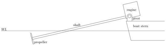
Figure 1.
Typical configuration of long-tail boats in ASEAN.
Since there is no clutch, the starting torque is relatively high and may prevent the engine to start properly if the propeller is immerged in water. Practically, to start the engine, the driver must lift the propeller out of water to eliminate the hydrodynamic torque. Once the engine and the propeller are well running, the driver gradually sinks the propeller into water to propel the boat.
Another problem with the no-clutch installation occurs when slowing the boat. As the engine rotational speed is low, the engine-generated torque is low as well. At some point, the generated torque is not enough to counter the hydrodynamic torque and the engine is forced to stop. Practically, when slowing the boat, the driver has to lift the propeller out of water as well, unless he wants to stop the engine.
2.2. Internal Combustion Engine Honda GX270
Examples of engine size can be found in [2]. The article showed that small, long-tail fishing boats in Kaoseng fishing community on the Coast of Songkhla Lake in Thailand employed engines ranging from 6.5 HP (4.8 kW) to 11.5 HP (8.5 kW).
The GX series internal combustion engine from Honda is one of the most popular engines for motorized long-tail boat. It ranges from GX100 to iGX800 with displacement from 98 up to 779 cm3 [7]. Honda GX270 engine is suitable for a small, long-tail boat. Figure 2 shows Honda GX270 engine mounted with long-tail propulsion system. All components are in the same packaging. It can be easily mounted and unmounted from the boat. Honda GX270 engine’s performance curves are shown in Figure 2. It can produce maximum torque of 19.1 Nm at 2500 rpm, maximum power of 6.3 kW at 3600 rpm and continuous rated power of 5.1 kW at 3600 rpm. Its dry weight is 25.8 kg. It can weigh around 30 kg with lubricant and fuel. In the current paper, the Honda GX270 engine is used to compare with the designed E-engine for a small, long-tail boat.
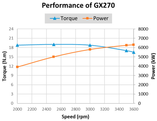
Figure 2.
Performance of Honda GX270 engine [7].
2.3. E-Propulsion Proposal
A complete electrical propulsion system for E-boat application is presented in this section. It comprises of an electric motor, battery packs, transmission shaft, propeller, electric control unit and instrument cluster, as shown in Figure 3. The motor is connected to the propeller via a long-tail shaft. It is mounted on a pivot engine stand so the driver can rotate the propeller left-right and up-down.
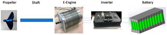
Figure 3.
E-propulsion architecture.
As mentioned earlier, a long-tail boat using ICE without clutch may suffer from low starting engine torque. The propeller must be lifted out into the air before the engine can be started. Whilst an electric motor has high starting torque, the propeller can be started in the water without any problem. Another advantage of the E-propulsion system is regenerative braking. It can apply negative torque to the propeller and regenerate electric energy back to the battery packs. A conventional long-tail boat using ICE without clutch and gearbox cannot generate reverse thrust. Moreover, the propeller must be lifted into the air to prevent the engine stalling.
3. Design Calculations of E-Engine for Long-Tail E-Boat
Even for the electric vehicle application, the low-cost asynchronous machine is well known by its simple manufacturing and reliability compared to the permanent magnet synchronous motor [8,9]. The drawback of this technology is the lower efficiency. It can be solved by using the copper rotor cage instead of the traditional aluminum rotor cage as Tesla model S and X [9]. Therefore, the asynchronous machine can be a good candidate for E-boat application developed for ASEAN emerging markets.
3.1. Electromagnetic Design Calculations
Using the same design method as [10], a three-phase asynchronous machine with copper cage rotor is designed for E-boat application. Indeed, a 1D analytical model of induction machine is used during the sizing step. Then the 2D finite element analysis is performed in order to validate this design in term of electromagnetic torque, torque oscillation, harmonic currents and losses. Desired peak torques are reached by tuning slip and motor voltage. The motor is cooled by the natural wind while operating with the help of cooling fins perpendicular to the shaft. Table 1 shows the volume, dimensions, and performances of this E-Engine for E-Boat. Figure 4 shows the cartography of efficiency in the whole of torque speed range of the designed E-engine. The efficiency of each operating point in this cartography is maximized by searching a set of optimum of the slip and motor voltage. The maximum torque at low speed and the maximum power are 26 Nm and 7.8 kW respectively. The top speed of motor is 6000 rpm. The weight and the volume of the motor are only 14.8 kg and 4.6 L.

Table 1.
E-engine design parameters and performances.
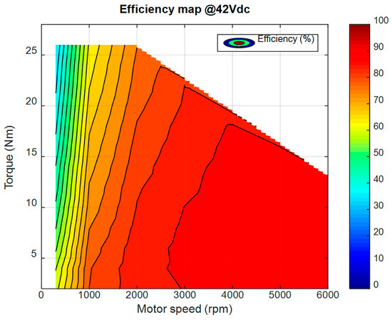
Figure 4.
Efficiency map of E-engine for E-boat.
E-engine has several advantages comparing to ICE (Figure 2 and Figure 4). The first one is the maximum torque (26 Nm) produced at very low speed and large range from 0 rpm to 2000 rpm. The second advantage is the capability of operating in high speed (up to 6000 rpm) of E-engine using field-weakening technique. The third one is the much better efficiencies of E-engine compared to the ones of ICE. A large area of efficiency between 80% and 90% can be observed in Figure 4. The next section details the thermal calculations related to the specific E-boat applications.
3.2. Thermal Calculations
Long-tail boat drivers usually apply torque for a short period to accelerate the boat, then they latch the accelerator. The propeller shaft is occasionally lifted into the air to prevent engine from stalling and to avoid floating debris. S3 IEC duty cycle can represent this kind of operation. A S3 duty cycle comprises of a time of constant load operation and a time of no-load. In this study, E-engine’s thermal behavior was computed over S3 10% and S3 30% at power of 7.5 kW and rotational speed of 3600 rpm.
Thermal behavior of E-engine was performed using lump-parameter model. It comprises of a number of thermal resistors (Rth), thermal capacitors (Cth) and power sources (Pth). A simplified model was developed, based on models proposed in [11,12,13,14]. There are 8 nodes, 11 thermal resistors, 7 capacitors and 5 power sources as shown in Figure 5. Rth and Cth depend on motor geometries, material and cooling method. For radial heat conduction, Rth of an element is computed as:
where k is thermal conductivity coefficient, rint is internal radius, rext is external radius, L is length and θ is open angle as shown in Figure 6.
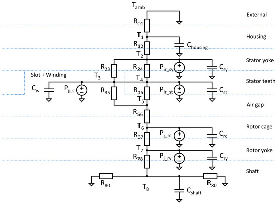
Figure 5.
Thermal model.
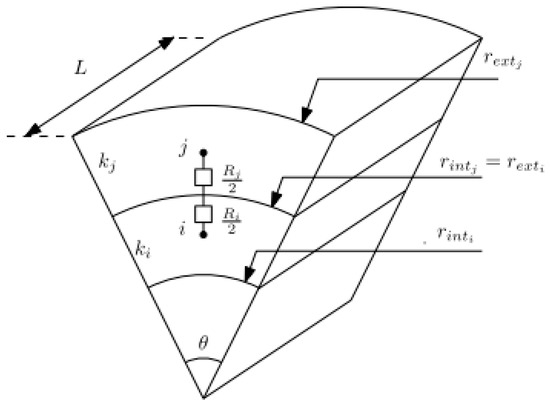
Figure 6.
Thermal resistance of radial convection.
Convection heat transfer is considered at the external housing and the air gap. Rth due to heat convection can be computed as:
where A is heat exchange surface and h is heat convection coefficient.
h at the air gap and external frame can be expressed as:
where Nu is Nusselt number, l is length of air gap or external frame. For air gap, Nusselt number is as function of Taylor number which is obtained empirically. For external housing, a force convection heat transfer is considered. Nusselt number depends on air speed and length of motor housing. Thermal coefficient calculations are explained in more details in [11,12,13,14].
Figure 7 shows thermal simulation result on S3 10% duty cycle. The duty cycle was repeated until the maximum temperature between two adjacent cycles was less than 1 °C. At this stage, the E-engine thermal behavior was considered steady state. The winding temperature reaches 64 °C steady state temperature after 8 repeated cycles. The rotor cage temperature stabilizes at 85 °C. This S3 10% duty cycle is far lower than maximum allowable winding and rotor temperatures.
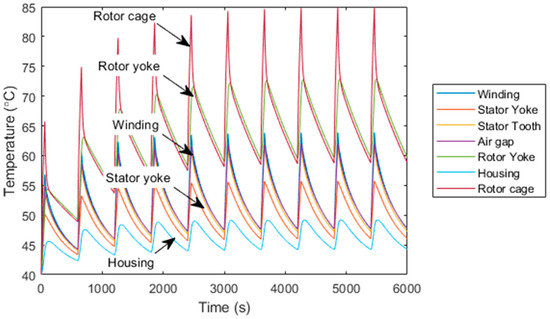
Figure 7.
Thermal simulation for S3 10% duty cycle.
The simulation result on S3 30% duty cycle is shown in Figure 8. The winding temperature only reaches 101 °C while the rotor temperature reaches 165 °C. The first one is far from the class H limit (180 °C) chosen in the design and the second one gets closer to the thermal-electromechanical limit when operating at high speed with some safety margin.
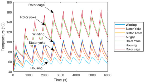
Figure 8.
Thermal simulation for S3 30% duty cycle.
4. Prototype and Experimental Testing
4.1. Prototype
A prototype (Figure 9) of E-engine has been manufactured based on the design described above. Electrical laminations were cut by an electrical discharge machining and welded together. The three-phases stator winding schema is presented in Figure 10. Copper cage rotor was die-casted.
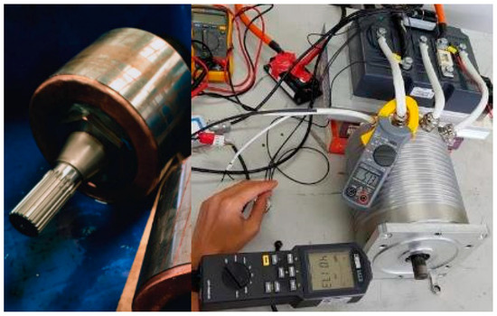
Figure 9.
Copper rotor and E-engine prototype at no-load testing at 4017 rpm.
Figure 10.
Winding schema of E-engine.
Figure 9 also shows the no-load test at 4017 rpm of the E-engine. The E-engine is controlled by an inverter which is fed by a simulator battery in the test-bench.
4.2. Experimental Results
Figure 11 shows the prototype mounted on the test-bench in order to test the performances of this designed E-engine. The load machine allows to pilot the speed and undergo the torque and power produced by the machine under test. The specimen is controlled in torque mode by the inverter. The electric power is fed via inverter by a battery simulator. The experimental torque and electric power are measured by torque meter and power analyzer. The calibration of the motor control map is firstly realized. Then, some experimental results will be tested.
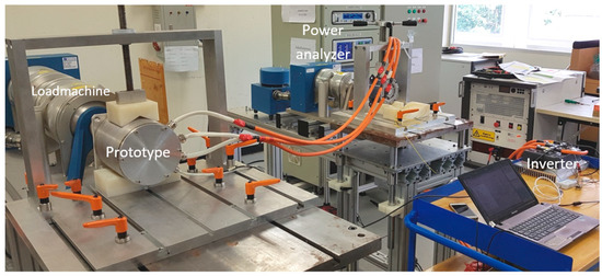
Figure 11.
Experimental measurement on test-bench.
The maximum torque at 0 rpm is measured in Figure 12. The rotor of the specimen is blocked in this test. The E-engine is capable to produce 25.87 Nm that is very close to the simulation results in Figure 4.
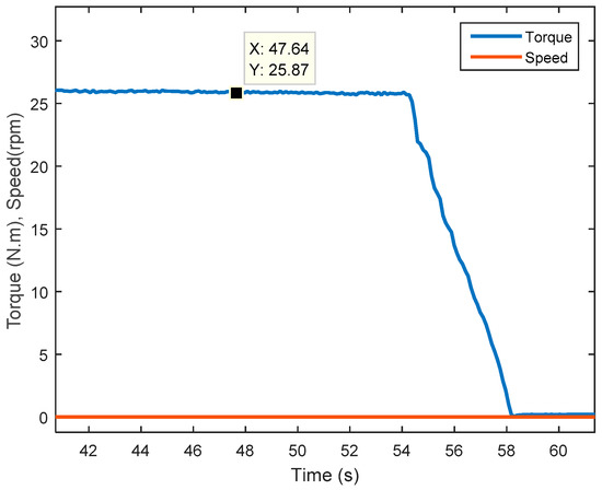
Figure 12.
Peak torque at 0 rpm (blocked rotor) with 275 A.
Figure 13 shows the measured peak performances (torque and power) of E-engine prototype in the whole speed range. This designed E-engine can produce more maximum torque and power than ICE’s Honda GX270 (25.8 Nm and 7.8 kW vs. 19 Nm and 6.3 kW) with a reduction of engine weight (−43%).
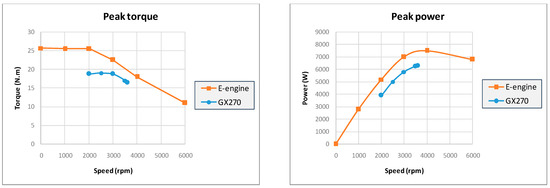
Figure 13.
Peak performance in measurement at 42 Vdc of E-engine and comparison with ICE Honda GX270.
The rising temperatures of the peak performance operating point (maximum torque 25.8 Nm at 1000 rpm) of prototype is shown in Figure 14. At this point, after 170 s (2.83 min), the maximum temperature of stator winding reaches only 103 °C. Using thermal class H, the E-engine can support a longer period at peak performance operation.
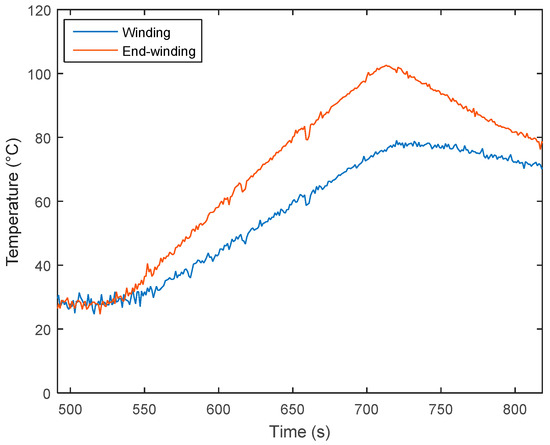
Figure 14.
Rising temperatures of operating point of peak torque at 1000 rpm.
Figure 15 shows the continuous performance test of 3 kW at 4000 rpm. A fan is used during this test to simulate the wind flow of 5 m/s. After 4250 s (71 min), the temperatures of E-engine are stabilized. The winding temperatures reach 150 °C steady state.
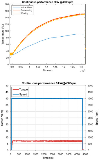
Figure 15.
Rising temperatures at the operating point of continuous performance 3 kW at 4000 rpm during 71 mn.
These experimental tests prove the design calculations of E-engine for E-boat application and its margin capability.
5. Comparison with the ICE Engine
From the perspective of engine performance, torque and power, it is clear that the proposed E-engine running at 42 Vdc can replace the ICE Honda GX270 as shown in Figure 13. The E-engine is also smaller and lighter as shown in Table 2. This allows more possibility to employ the E-engine instead of the ICE.
Table 2.
Comparison between the ICE Honda GX270 and E-engine.
However, the E-engine must include an inverter and battery pack in operations. The inverter weighs only about 2 kg but the weight of battery pack is significant. The weight of battery pack can be a main drawback of the E-propulsion system. For 1 h of operation, 3 kWh or equivalent of 15 kg of battery packs are required while Honda GX270 needs only 2.4 l or approximately 2 kg of petrol. Nevertheless, in this case, the total weight of E-propulsion system would be about 30 kg which is comparable with Honda GX270 system of 28 kg (petrol included). A trade-off between weight, range and cost must be considered. This topic will be analyzed in a future work.
Another advantage of the E-propulsion is the flexibility over the weight distribution for the E-boat. The E-engine, the inverter, and the battery packs are not necessary to be at the same place. Especially, the battery pack can be used as ballast to better allocate the boat center of gravity both vertically and longitudinally which eventually improves the boat stability.
6. Conclusions
The design and comparison of electric engine and internal combustion engine for long-tail boat in ASEAN is presented. The interesting experimental results of E-engine prototype on the test-bench validate the electromagnetic-thermal design calculation method. An advantage of the designed E-engine over the classic internal combustion engine (Honda GX270) for the long-tail boats is not only the generated torque at zero or low rotational speed, but also in terms of performances, volume, and weight (−43%). Due to the unique mechanical configuration of long-tail boats, the driver often lifts the propeller out of water to control the hydrodynamic torque; for example, when starting the engine or slowing the boat. However, the E-engine allows to overcome this problem with the high torque at zero and low rotational speed.
Author Contributions
This article presents the collective work of all authors (V.T.T., P.N.H., S.P. and S.K.). All authors have read and agreed to the published version of the manuscript.
Funding
This research received no external funding.
Conflicts of Interest
The authors declare no conflict of interest.
References
- Kaewkhiaw, P.; Yoshitake, A.; Kanemaruand, T.; Ando, J. Experimental and Numerical Study of Propeller Performance for Long-Tail Boat in Thailand. In Proceedings of the Japan Society of Naval Architects and Ocean Engineers, Hyogo, Japan, 8 June 2015; Volume 20, pp. 407–410. [Google Scholar]
- Chainarong, S.; Sitthipong, S.; Meengam, C. Influence of stress to mechanical failure of long tail shaft in the power transmission system on local fishing boat. SNRU J. Sci. Technol. 2016, 8, 127–132. [Google Scholar]
- Paul, D. A History of Electric Ship Propulsion Systems. IEEE Ind. Appl. Mag. 2020, 26, 9–19. [Google Scholar] [CrossRef]
- Guellard, B.; de Montgros, X.; De La Barriere, P.P.; Wolfensberger, G.; D’oliveira, P. An overview of electric and solar boats market in France. World Electric. Veh. J. 2013, 6, 75–87. [Google Scholar] [CrossRef]
- Rajper, S.Z.; Albrecht, J. Prospects of Electric Vehicles in the Developing Countries: A Literature Review. Sustainability 2020, 12, 1906. [Google Scholar] [CrossRef]
- Postiglione, C.S.; Collier, D.A.; Dupczak, B.S.; Heldwein, M.L.; Perin, A.J. Propulsion system for an all electric passenger boat employing permanent magnet synchronous motors and modern power electronics. In Proceedings of the 2012 Electrical Systems for Aircraft, Railway and Ship Propulsion, Bologna, Italy, 16–18 October 2012; pp. 1–6. [Google Scholar]
- Internal Combustion Engine Honda Gx270. Available online: https://engines.honda.com/models/model-detail/large-gx (accessed on 20 February 2021).
- Frieske, B.; Kloetzke, M.; Mauser, F. Trends in Vehicle Concept and Key Technology Development for Hybrid and Battery Electric Vehicles. World Electric. Veh. J. 2013, 6, 9–20. [Google Scholar] [CrossRef]
- Sieklucki, G. An Investigation into the Induction Motor of Tesla Model S Vehicle. In Proceedings of the 2018 International Symposium on Electrical Machines (SME), Andrychów, Poland, 10–13 June 2018; pp. 1–6. [Google Scholar]
- Tuan, V.T.; Kreuawan, S.; Somsiri, P.; Nguyen, H.P. Low cost motor drive technologies for ASEAN electric scooter. J. Electr. Eng. Technol. 2018, 13, 1578–1585. [Google Scholar]
- Tungpimolrut, K.; Tuan, V.T.; Kreuawan, S.; Nguyen, H.P. Design of e-scooter motor with thermal analysis based on driving cycle. In Proceedings of the Grand Renewable Energy, Yokohama, Japan, 17–22 June 2018; pp. 300–304. [Google Scholar]
- Boglietti, A.; Cavagnino, A.; Lazzari, M.; Pastorelli, A. A simplified thermal model for variable speed self cooled industrial induction motor. IEEE Trans. Ind. Appl. 2003, 39, 945–952. [Google Scholar] [CrossRef]
- Miller, P.H.; Roberts, D.; Turner, D.R. Lumped parameter thermal model for electrical machine of tefc design. Electr. Power Appl. IEE Proc. B 1991, 138, 205–218. [Google Scholar] [CrossRef]
- Pawlus, W.; van Khang, H.; Hansen, M.R. Identification of induction motor thermal model for improved drivetrain design. In Proceedings of the 2016 XXII International Conference on Electrical Machines (ICEM), Lausanne, Switzerland, 4–7 September 2016; pp. 1776–1782. [Google Scholar]
Publisher’s Note: MDPI stays neutral with regard to jurisdictional claims in published maps and institutional affiliations. |
© 2021 by the authors. Licensee MDPI, Basel, Switzerland. This article is an open access article distributed under the terms and conditions of the Creative Commons Attribution (CC BY) license (http://creativecommons.org/licenses/by/4.0/).