Abstract
The advantages of LoRaWAN over conventional networks (GSM, 4G, 5G) in terms of investment and operating costs have been proven for network coverage in urban and rural areas. However, the theoretical coverage compared to the reality on the ground and the quality of service (QoS) provided remain very relative and depend on several technical factors, subject to increased research. Several recent approaches and hardware specifications recommended adding gateways as a solution to improve the LoRaWAN QoS indicators, mainly for high-traffic situations. However, such a solution will not work in all real-life scenarios since many factors must be considered. This article presents a study of the factors impacting the LoRaWAN QoS in the case of the usage of multiple gateways by exploring different scenarios to show how the payload length impacts the whole network’s packet delivery ratio (PDR) and how it interacts when enhancing the GW number with and without confirmed traffic. Based on the simulation results, increasing the number of gateways can negatively impact the network’s ability to support higher payload packets, especially in a high-traffic scenario. More precisely, we can say that for a low number of GWs, it is more appropriate to use a high payload length since we can achieve a high PDR. Nevertheless, with a high number of GWs, it would be more appropriate to use a low payload length to achieve a good PDR. Similarly, our analyses show that increasing the number of gateways ensures a better PDR but with a significant packet loss at the gateways, which is synonymous with higher energy consumption.
1. Introduction
Nowadays, the Internet of Things (IoT) has emerged as one of the most revolutionary events of this decade. This novel trend can generally be described as an ecosystem where ubiquitous sensors connect the Internet to the physical world. The IoT can also be defined as a network of physical objects known as “things” with varying degrees of sensing, processing, and communication capabilities that enables these objects to collect and exchange data. The contextualization of the different usage modes of connected objects in the smart city leads us to address the need for specific and objective planning for any rigorous deployment. This approach will be decisive for conceptual adjustment purposes and guarantees a better QoS. For an environment with high-traffic demand, the very rigorous regulations of the standard and the known shortcomings of the chirp spread spectrum (CSS) [1] modulation and the Pure ALOHA protocol (P-ALOHA) increase the loss rate packets due to collisions. Hence, finding the best way to respond to these issues while minimizing the infrastructure costs (CAPEX-OPEX) is necessary.
In the literature, several approaches recommended adding gateways (GWs) as a solution to improve the LoRaWAN QoS indicators, mainly for high-traffic situations. However, such a solution will not work in all cases since many factors need to be considered such as the packet payload size, the number of gateways to be used, the periodicity of sending data, etc. In addition, in dense networks, the degradation of network performance is proportional to the increase in the number of nodes.
In this paper, we present a study of the factors impacting the LoRaWAN QoS in the case of the usage of multiple gateways. First, we show through simulations the role of configuration in the congestion of a LoRa gateway operating in the industrial, scientific, and medical (ISM) band EU860-870. We also show the payload size effect on the QoS of a LoRaWAN network. For this, we simulate several multi-gateway scenarios by varying the sending packet frequency, the packet payload, the number of gateways, and the number of nodes. Our results clearly show that a one-gateway network comprising a thousand nodes transmitting small-sized messages at a reduced frequency can provide better QoS than a multi-gateway network with a transmission frequency of around one message every minute per node. This first observation motivated us to study multi-gateway behaviour to plan a better traffic-oriented architecture.
The main goal of this paper is to provide a behaviour study of the multi-gateway usage in LoRaWAN under high-traffic conditions. This study can help us to better understand the parameters that can impact network performance when increasing the number of gateways. In addition, in this study, we answer the following questions: What does adding gateways imply concerning network performance? Under which conditions can we add more gateways without losing performance quality?
The rest of this paper is organized as follows. In Section 2, we give an overview of LoRaWAN technology fundamentals and highlight the constraints. In Section 3, the related works about using multiple gateways in a LoRaWAN are discussed. In Section 4, we provide and discuss our simulation results. Finally, in Section 5, we conclude this paper with a global overview and give some perspectives.
2. Fundamentals of LoRaWAN Technology
The best-known low-power wide area network (LPWAN) technologies working on the unlicensed band are Sigfox [2] and LoRa [3]. However, the latter, which is the subject of our study, is the most popular thanks to some of its characteristics that are essential for some IoT applications such as smart cities and industry 4.0. Among these characteristics are the downlink channel, which is necessary for the functionalities of the control-command mode, the capacity of this technology to support traffic, and the consideration of mobility. LoRa remains the most widespread technology on the market and the most documented in terms of research thanks to its free media access control (MAC) LoRaWAN protocol promoted by the LoRa alliance [3]. LoRaWAN presents a better quality ratio compared to the investment costs for the smart city, smart grids, smart farming, and remote monitoring systems [4]. Its architecture is star-of-star, as depicted in Figure 1, where each element works at one or more OSI layers (physical (L1), datalink (L2), network (L3), transport (L4), session (L5), presentation (L6), application (L7)). Specifically, the end device works at layers L1 and L2. The GW works at layers L1, L2, L3, and L4. The servers work at all layers.
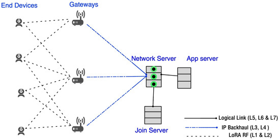
Figure 1.
LoRaWAN network architecture.
2.1. LoRa (Long Range)
The term LoRa or LoRa RF (long-range radio frequency) refers to the technology owned by SEMTECH [5]. Its CSS modulation allows linear broadband frequencies, making the signal robust to channel noise. In addition, thanks to the orthogonal channels, communications with different data rates do not interfere with each other, which presents a significant advantage in overcoming interferences. At the PHY level, LoRa offers the possibility of optional choices to transmitters from five parameters, namely: the Central Frequency (), Transmission Power (), Spreading Factor (), Bandwidth (), and Coding Rate (). However, the signal range and transmission bit rate () in a LoRa network depend on the used combination of these parameters and are defined by the following expression:
The spreading factor is equal to the number of bits per symbol. We can deduce from Equation (1) the modulation speed noted (symbol rate) and expressed in bauds in Equation (2):
Depending on the combination of these parameters, the LoRa modules allow obtaining 28 different flow rate values from the transmission between 0.3 kbits/s and 11 kbits/s. For example, Figure 2 shows the impact of these parameters on the bit rate () and symbol rate (). In addition, this figure illustrates how the LoRa communication range and throughput (for the 868 MHz band) are impacted by the bandwidth values, the signal’s output power, and the spreading factor used.
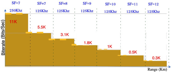
Figure 2.
LoRaWAN bit rate variation according to and parameters [5].
Although LoRa has advantages over competing technologies, its simple ALOHA channel access method is considered the main weak point for possible traffic-oriented scalability. For this channel access method, a station can transmit whenever it wants and waits for an acknowledgement (ACK) (in the confirmed traffic case). The terminal retransmits its frame if no ACK has been received from the network server after a fixed period. The corresponding information is corrupted and lost whenever two or more packets collide. Thus, the packets in question must be retransmitted, leading to additional bandwidth use and a reduction in the network’s capacity.
2.2. LoRAWAN (Long-Range Wide-Area Network)
LoRaWAN is an open-source protocol developed and supported by the LoRa Alliance community. This MAC protocol offers self-optimization possibilities thanks to a few native mechanisms, such as the adaptive data rate (ADR) or the transmission management based on channel listening called listen before talk (LBT) and adaptive frequency agility (AFA), which are similar to the CSMA channel access protocol [1]. These mechanisms aim to reduce the DC limitation, which corresponds to the maximum occupation time authorized on an ISM channel, and minimize interference and power consumption while ensuring long-range communication.
2.3. Regulations
In Europe, LoRa operates in the 863–870 MHz frequency band. It can work in two sub-bands, one at 868 MHz, which offers three LoRa channels at 125 kHz, and the other at 867 MHz, which offers five LoRa channels at 125 kHz. The gateway should be able to listen to all channels simultaneously. The number of channels that can be used is 8 + 2 (1 LoRa + 1 FSK) uplink and 1 downlink, but this depends on the specific regulations adopted for the gateway. In the case of SEMTECH, LoRaWAN by default uses three channels of the 868 MHz band, but the 867 MHz band can also be configured in the uplink. There is one 869.525 MHz downlink channel with fixed and settings (12 and 125 kHz). Depending on the sub-band used, the regulations define a channel occupation time (DC) and the TP to be used. For the g1 sub-band, the DC is limited to 1% with the LBT and AFA operations for a maximum transmission power (MTP) of 14dBm. The g3 sub-band is eligible for an occupancy rate of 10% (LBt + AFA) and a transmission power of 27dBm. Table 1 summarises the different sub-bands used by LoRaWAN technology and the corresponding power and DC, whereas Table 2 presents the LoRaWAN default channels.

Table 1.
Frequency plan sub-band g EU868-SEMTECH with MTP and DC.

Table 2.
LoRaWAN default channels.
2.4. LoRaWAN Limits
LPWAN technologies are often requested for their large-scale and low-cost coverage benefits. As they are designed for this purpose, thousands of nodes with varied application requirements can be requested. From the above, we can summarise the main factors impacting the performance of LoRaWAN in three points:
- The radio channel degradation: the CSS modulation uses a constant bandwidth for signal broadcasting [6], which makes the latter more robust against phenomena related to the propagation of electromagnetic waves. Despite this advantage, the various phenomena related to the propagation [7] of electromagnetic waves, the frequency collision, and the Doppler effect, significantly degrade the network QoS using this technology.
- ISM band regulations: as detailed above, LoRaWAN is subject to strict regulations regarding the occupation time of the ISM band. These regulatory limits constitute a blocking factor for a traffic-oriented network, which is typical for a network in which the packet transmission sequence per node is very high and counts in thousands for a limited number of gateways. For example, for the g1 band, with a maximum spreading factor and a bandwidth of 125 kHz, the number of messages sent in all channels per minute is around four. Even if the LBT and AFA make it possible to bypass the limitation rules, these mechanisms are still not well documented by SEMTECH.
- The end devices (EDs) and gateway capacity: gateways play an essential role in the LoRaWAN architecture. For networks with constrained nodes that do not support the IP stack, such as class 0 objects governed by IETF RFC 7228 [8], the gateway is the essential element in the chain. For a network using objects of this class, the network’s capacity can be reduced to the hardware limits of the latter. De facto, the channels’ saturation at the gateway level will be characterized by congestion, which will generate a loss of packets on reception, proportional to the traffic. Such observation has been demonstrated in several works such as in [9,10,11]. This problem persists even for commercial gateways supporting eight channels of parallel communications.
3. Related Works
LoRaWAN was designed for long-range and low-speed communication. It naturally displays shortcomings in responding to the challenges of current applications, requiring high data traffic. The shortcomings in this sense have also been confirmed thanks to the latest works [11,12,13] using effective simulation tools and considering a more realistic environment of the LoraWAN architecture. In a LoRa network, the selection of the spreading factor is position based. Nodes connect to gateways on the simple criterion of signal strength (RSSI), and spreading factors are allocated to nodes based on their distance from the gateway.
LoRaWAN protocol uses the ADR mechanism to correct deficiencies at the low layer (PHY) level. This key mechanism allows terminals to dynamically change the transmission parameters of the latter according to a rate calculated on the average of the last 20 messages received by the receiver to improve the success rate of packets and reduce power consumption.
The ADR mechanism has been the subject of increased research. In [14], this mechanism was highlighted as a perspective for adapting the LoRaWAN network to a traffic-oriented urban scenario. Li et al. [15] demonstrated that the ADR is best suited to a static and stable link environment and struggles in the face of network dynamics. In [13], the authors demonstrated that the ADR mechanism does not allow for obtaining significant results in the presence of congestion, which will affect the reception of the message on the uplink (UL), which is necessary for triggering this mechanism. Proposals for improved protocols of the said mechanism using simple ALOHA have been made in works such as [7] for a single-gateway network and [10] for a multi-gateway network.
In [16,17], the authors highlighted the technical perspectives at the level of the lower MAC/PHY layers and the capacity for self-adaptation of the parameters of the LoraWAN network to improve the QoS. In [18], the authors showed that increasing the number of gateways may be an obstacle given the material and regulatory constraints regarding channel occupation time and simultaneous reception.
All these conclusions allow us to appreciate the contribution of the ADR to improving the quality of service of the LoRaWAN network. Although this mechanism claims to re-adapt the configuration of the terminals by modifying the parameters to maintain quality, this is not a practical solution since the development of new simulation tools with scenarios very close to reality and based on coherent mathematical models has made it possible to highlight the shortcomings of such an approach.
More precisely, the implementation of the ADR in the NS-3 module has allowed for more realistic analyses of the ability of this mechanism to optimize the network. Thus, it is possible to perform a precise diagnosis and highlight the fundamental limits of the multi-gateway network. In [19], the authors showed that the use of a confirmation message (ACK) is a degrading factor for the channel due to the DC limitation of the gateways.
In [6], by implementing the CSMA access method protocol as an improvement at the LoRaWAN level, the authors demonstrated a considerable reduction in the packet collision rate, which led to an improvement in the QoS. However, using this method negatively impacts power consumption for a medium-sized network. In [20], Ameer et al. proposed an algorithm and demonstrated that it could achieve targeted performance more than the native ADR. Kim et al. [21] also demonstrated that this mechanism responds poorly to high levels of packet collision, as in the case of dense networks.
In [22,23], the authors mentioned the impact of LoRa packet size on reception success but they assumed that it was harmless to network performance.
In [24], the authors argued that the packet transmission time (ToA) is an essential indicator without demonstrating and highlighting its impact on any dense network deployment planning.
We note that all the related works cited above, including those proposing an increase in the number of gateways, did not address the issue of gateway performance as a function of packet size or the real impact of the traffic generated by the packet transmission period.
Given the above, we diagnosed the LoRaWAN QoS through scenario simulations that mimicked a traffic-oriented multi-gateway infrastructure deployment. Our analysis allowed us to better understand multi-gateway behaviour, mainly the advantages and disadvantages that it has for a network with dense traffic.
4. Simulations and Results Analysis
To study multi-gateway behaviour and its correlation with the parameters, we conducted several simulations using the NS-3 simulator. Our simulation took into consideration five parameters, which are the number of EDs deployed in the network, the payload length, the generation packet period, the number of deployed gateways, and whether or not the traffic required an ACK. Table 3 summarises the used simulation parameters. We note that we used the LoRaWAN implementation available in [25]. In addition, we used the Simulation Execution Manager (SEM) for NS-3 [26] to manage all the discussed parameters. We also note that the obtained results were the average of ten simulations for each parameter combination. The network formed a star topology architecture composed of several nodes ranging from 100 to 1000, deployed randomly over a radius of 7.5 km. The number of GWs varied from 1 to 5 with a predefined fixed position. The first GW was placed at the centre of the network. The simulation time was 60 min, where each node sent a data packet with a frequency varying from one packet per minute to one packet every 17 min. The data payload varied from 10 to 100 bytes.

Table 3.
Simulation parameters.
4.1. Performance Metrics
For each simulation, we computed the following metrics:
- A-PDR: the aggregated packet delivery ratio by considering all deployed gateways. By aggregated, we mean that a packet was received by at least one GW.
- Pkt-Sent: the number of packets sent by all EDs in the network. We note that this number also included the retransmitted packets in the case of confirmed traffic.
- LPI: refers to the number of lost packets at the gateway due to interference. The value of this metric was the average for all used gateways.
- LPTX: refers to the number of lost packets at the gateway since it was in the transmitting phase (TX), typically, when the gateway sent the ACK to the ED. The value of this metric was the average for all used gateways.
We note that we only show a part of the obtained results to avoid redundancy. Generally, we do not display all the results for other generation period traffic since our goal was to study multi-gateway behaviour in high-traffic conditions. However, we can confirm that we still observed the same trend in those results with a frequency of 1 pkt every 3, 5, 7, and 9 min but with slight differences.
4.2. Studied Scenarios
In this subsection, we study three scenarios to show how the payload length impacts the A-PDR and how it interacts when varying the sending packet frequency, the packet payload, the number of gateways, and the number of nodes, with and without confirmed traffic.
4.2.1. Effect of the Payload Length
Figure 3 shows the results obtained for two and five gateways while varying the payload length with a frequency of 1 packet/min and unconfirmed traffic. We can see from Figure 3a that the A-PDR was high for payload lengths from 60 to 100 bytes. The same figure shows that the A-PDR decreased significantly by using a payload length from 10 to 50 bytes. In addition, Figure 3a tells us that when the number of EDs increased, the achieved A-PDR decreased regardless of the payload length. We can explain this behaviour by the fact that using a low payload length (10 to 50 bytes) increases the number of sending packets over the network considerably, mainly when the number of EDs increases, as we can see in Figure 3c. Thus, with such a high number of packets sent, the gateway suffers from a high interference level, leading to packet loss, as shown in Figure 3e.
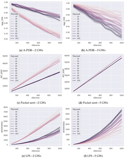
Figure 3.
Performance results for two and five gateways while varying the payload length with a frequency of 1 packet/min—unconfirmed traffic.
However, we can see that we had the opposite behaviour concerning the A-PDR and LPI for a network with five gateways. As shown in Figure 3b, the network achieved a better A-PDR in the case of a low payload length. In addition, the number of sending packets was nearly the same with a network of five gateways while varying the payload length, as we can see in Figure 3d. Moreover, in Figure 3f, we can see that with a high payload (ex. 100 bytes), the network suffered from a high interference level compared to the case of using a low payload. Such behaviour is related to the fact that using more gateways will make the ED use a low value, as shown in Figure 4. More precisely, Figure 4a shows that when we used one gateway, most of the EDs had an equal to 10, 11, or 12 since they were located far away from the gateway. However, with five gateways, as depicted in Figure 4b, most of the EDs used an of 7. Such hidden behaviour had a significant impact on network performance. In fact, when an ED used a low (e.g., ), it could send more packets, as we can see in Table 4 and Table 5. In addition, the airtime was low compared to using a high . In addition, for the same used , the payload length significantly impacted the airtime and the number of allowed messages to transmit.
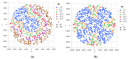
Figure 4.
(a) SF allocation with 2 GWs; (b) SF allocation with 5 GWs. allocation according to the number of gateways deployed in the case of 1000 EDs.

Table 4.
Airtime and number of allowed messages according to different data rates for a payload of 10 bytes [27].

Table 5.
Airtime and number of allowed messages according to different data rates for a payload of 100 bytes [27].
Figure 5 shows the results obtained for two gateways while varying the payload length with a different frequency of sending packets and unconfirmed traffic. Typically, with 1 packet every 3, 5, 7, and 9 min, the behaviour was still the same as we can see in Figure 5a–d. These figures confirm that using a low payload length (10 to 50 bytes) achieves a low A-PDR compared to a higher payload length (60 to 100).
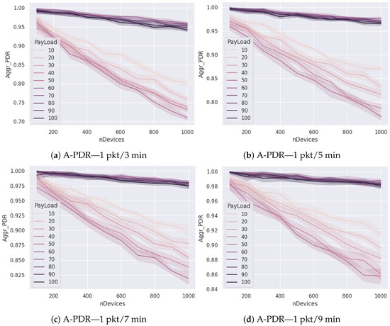
Figure 5.
Aggregated PDR results for two gateways while varying the payload length with a frequency of one packet every 3, 5, 7, and 9 min—unconfirmed traffic.
4.2.2. Effect of the Number of Gateways
Figure 6 shows the obtained results for 10 and 100 bytes of payload length while varying the gateway number with a frequency of 1 packet/min and with unconfirmed traffic. We can see from Figure 6a,b that, as expected, the more gateways we used, the higher the A-PDR that was achieved. In addition, we can see that the A-PDR decreased as the number of EDs increased, mainly in the case of 100 bytes. From Figure 6c,d, we can see clearly that when the number of gateways increased, the number of packets sent also increased, regardless of the payload length. Such behaviour can be explained by the fact that using more gateways will make the ED use a low value (e.g., ), which allows them to send more packets, as we can see in Table 4 and Table 5. Finally, Figure 6e,f show that by increasing the number of gateways, the LPI indicator decreased considerably compared to the case of using one or two gateways. In addition, using a high payload length led to a low LPI compared to using a low payload length. As previously stated, such behaviour can be explained by the fact that with more gateways, the ED uses a low value (e.g., ), which leads it to send packets with low airtime. So, gateways will have a low probability of facing interferences and thus lose packets.
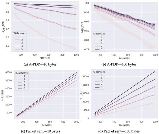
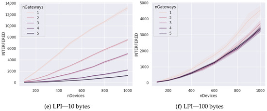
Figure 6.
Performance results for a payload of 10 and 100 bytes while varying the number of gateways with a frequency of 1 packet/min—unconfirmed traffic.
Figure 7 shows the results obtained for a payload of 100 bytes while varying the gateway number with a different frequency of sending packets and unconfirmed traffic. Typically, with one packet every 3, 5, 7, and 9 min, the behaviour was still the same, as we can see in Figure 7a–d. These figures confirm that increasing the number of gateways leads to a higher number of packets sent.
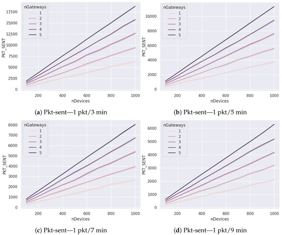
Figure 7.
Pkt-sent results for a payload of 100 bytes while varying the number of gateways with a frequency of one packet every 3, 5, 7, and 9 min—unconfirmed traffic.
4.2.3. Effect of the Confirmed Traffic
Figure 8 shows the obtained results of the LPTX metric in the case of confirmed traffic while varying the payload length and the number of gateways with a frequency of 1 packet/min.
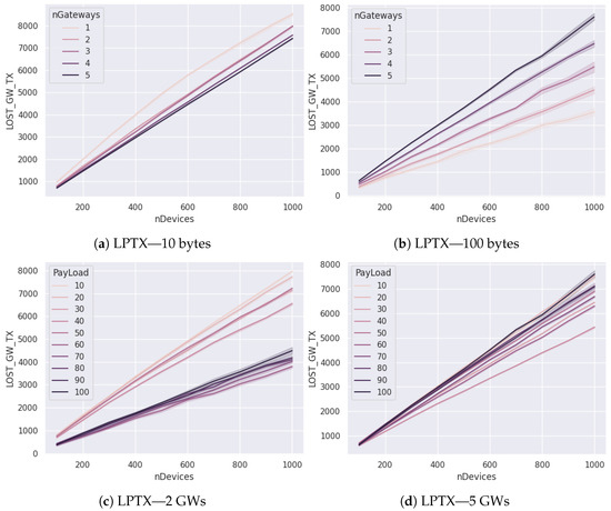
Figure 8.
Number of lost packets at the gateway since it was in the transmitting phase while varying the number of gateways (a,b) and the payload length (c,d) with a frequency of 1 packet/min—confirmed traffic.
We can see in Figure 8a that with a low payload (10 bytes in this case), using a low number of GWs led to a high LPTX value. We note that the difference between using one GW and five GWs never exceeded 1000 lost packets, and this was the advantage of using more gateways. However, we see the opposite behaviour in Figure 8b, which shows the LPTX value when using a high payload (100 bytes). In this case, with one GW, we achieved a shallow LPTX value compared to the case of using five GWs, mainly when the number of EDs increased. We can explain this by the fact that using more gateways increased the number of sent packets since the ED used a low value, allowing it to send more packets. In addition, the number of retransmissions naturally increased when an ACK was required at the ED (confirmed traffic).
Figure 8c,d show the obtained LPTX value for the case of two and five gateways, respectively, while varying the payload length. In Figure 8c, we can see that with a low payload length (10 to 50 bytes), we obtained a very high LPTX value compared to the case of using a high payload length (more than 60 bytes), mainly when the number of EDs increased. In Figure 8d, we can see that the LPTX value remained roughly the same for five gateways, even if we vary the payload length.
In summary, our study of these three scenarios has made it possible to answer our initial questions. Typically, adding gateways implies that the network performance decreases in the case of high traffic. So, we can add more GWs without losing performance only if we choose the right payload length.
5. Conclusions
In this paper, we conduct a behaviour study of multi-gateway usage in LoRaWAN under high-traffic conditions. For this, we simulate several scenarios to show how the payload length impacts the PDR of the whole network and how it interacts when varying the sending packet frequency, the packet payload, the number of gateways, and the number of nodes, with and without confirmed traffic. As the main results, we can say that for a low number of deployed GWs, it is more appropriate to use a high payload length to achieve a high A-PDR. On the contrary, it is more appropriate to use a low payload length when the number of GWs increases. In addition, using several gateways can improve the network QoS; however, the right number of gateways to use must be based not only on the number of EDs deployed but also on the data flow to be generated. This flow can be determined by the sending data periodicity or by the packet’s payload length. In addition, we have seen through our work that adopting a multi-gateway strategy increases the number of nodes using lower spreading factors (). This behaviour makes the multi-gateway network fail in the case of high traffic, mainly when the packet payload increases. Therefore, a multi-gateway network is not a guarantee of optimization in all circumstances. Thus, we can have better results in terms of traffic by focusing on the proper settings. For future work, we plan to make a more extensive study by considering other metrics such as energy and latency.
Author Contributions
Conceptualization, K.S.A. and I.B.; methodology, K.S.A., I.B., A.A. and P.L.; validation, K.S.A., I.B., A.A. and P.L.; formal analysis, K.S.A., I.B., A.A. and P.L.; investigation, K.S.A. and I.B.; data curation, K.S.A. and I.B.; writing—original draft preparation, K.S.A. and I.B.; writing—review and editing, K.S.A., I.B., A.A. and P.L.; supervision, A.A. and P.L. All authors have read and agreed to the published version of the manuscript.
Funding
This research received no external funding.
Data Availability Statement
Not applicable.
Conflicts of Interest
The authors declare no conflict of interest.
Abbreviations
The following abbreviations are used in this manuscript:
| ACK | Acknowledgement |
| ADR | Adaptive Data Rate |
| AFA | Adaptive Frequency Agility |
| A-PDR | the Aggregated Packet Delivery Ratio |
| BW | bandwidth |
| CAPEX | Capital expenditure |
| CF | Central Frequency |
| CR | Coding Rate |
| CSS | Chirp Spread Spectrum |
| CSMA | Carrier Sense Multiple Access |
| DC | Duty Cycle |
| GW | Gateway |
| IoT | Internet of Things |
| ISM | Industrial, Scientific and Medical |
| LBT | Listen Before Talk |
| LPWAN | Low Power Wide Area Network |
| LoRAWAN | Long Range Wide Area Network |
| LPI | Lost Packets at the gateway due to Interference |
| LPTX | Lost Packet at the gateway since it is in the transmitting phase (TX) |
| MAC | Media Access Control |
| OPEX | operational expenditure |
| Pkt-Sent | Packets sent by all ED in the network |
| QoS | Quality of Service |
| SF | Spreading Factor |
| TP | Transmission Power |
References
- Reynders, B.; Pollin, S. Chirp spread spectrum as a modulation technique for long range communication. In Proceedings of the 2016 Symposium on Communications and Vehicular Technologies (SCVT), Mons, Belgium, 22 November 2016; pp. 1–5. [Google Scholar] [CrossRef]
- SigFox. Available online: https://sigfox.fr/ (accessed on 8 May 2022).
- LoRa Alliance. Available online: https://lora-alliance.org/ (accessed on 8 May 2022).
- Ertürk, M.A.; Aydın, M.A.; Büyükakkaşlar, M.T.; Evirgen, H. A survey on LoRaWAN architecture, protocol and technologies. Future Internet 2019, 11, 216. [Google Scholar] [CrossRef]
- Semtech LoRa Technology Overview. Available online: https://www.semtech.com/lora (accessed on 8 May 2022).
- To, T.H.; Duda, A. Simulation of LoRa in NS-3: Improving LoRa Performance with CSMA. In Proceedings of the 2018 IEEE International Conference on Communications (ICC), Kansas City, MO, USA, 20–24 May 2018; pp. 1–7. [Google Scholar] [CrossRef]
- El Chall, R.; Lahoud, S.; El Helou, M. LoRaWAN Network: Radio Propagation Models and Performance Evaluation in Various Environments in Lebanon. IEEE Internet Things J. 2019, 6, 2366–2378. [Google Scholar] [CrossRef]
- Terminology for Constrained-Node Networks, Internet Engineering Task Force, Request for Comments RFC 7228, mai 2014. Available online: https://www.ietf.org/id/draft-ietf-lwig-7228bis-00.html (accessed on 8 May 2022).
- Mikhaylov, K.; Petaejaejaervi, J.; Haenninen, T. Analysis of Capacity and Scalability of the LoRa Low Power Wide Area Network Technology. In Proceedings of the European Wireless 2016 22th European Wireless Conference, Oulu, Finland, 18–20 May 2016; pp. 1–6. [Google Scholar]
- Magrin, D.; Capuzzo, M.; Zanella, A. A Thorough Study of LoRaWAN Performance Under Different Parameter Settings. IEEE Internet Things J. 2020, 7, 116–127. [Google Scholar] [CrossRef]
- Van den Abeele, F.; Haxhibeqiri, J.; Moerman, I.; Hoebeke, J. Scalability Analysis of Large-Scale LoRaWAN Networks in ns-3. IEEE Internet Things J. 2017, 4, 2186–2198. [Google Scholar] [CrossRef]
- Magrin, D.; Centenaro, M.; Vangelista, L. Performance evaluation of LoRa networks in a smart city scenario. In Proceedings of the 2017 IEEE International Conference on Communications (ICC), Paris, France, 21–25 May 2017; pp. 1–7. [Google Scholar] [CrossRef]
- Capuzzo, M.; Magrin, D.; Zanella, A. Confirmed traffic in LoRaWAN: Pitfalls and countermeasures. In Proceedings of the 2018 17th Annual Mediterranean Ad Hoc Networking Workshop (Med-Hoc-Net), Capri, Italy, 20–22 June 2018; pp. 1–7. [Google Scholar] [CrossRef]
- Hauser, V.; Hégr, T. Proposal of Adaptive Data Rate Algorithm for LoRaWAN-Based Infrastructure. In Proceedings of the 2017 IEEE 5th International Conference on Future Internet of Things and Cloud (FiCloud), Prague, Czech Republic, 21–23 August 2017; pp. 85–90. [Google Scholar] [CrossRef]
- Li, S.; Raza, U.; Khan, A. How Agile is the Adaptive Data Rate Mechanism of LoRaWAN? In Proceedings of the 2018 IEEE Global Communications Conference (GLOBECOM), Abu Dhabi, United Arab Emirates, 9–13 December 2018; pp. 206–212. [Google Scholar] [CrossRef]
- Goursaud, C.; Gorce, J.M. Dedicated networks for IoT: PHY/MAC state of the art and challenges. EAI Endorsed Trans. Internet Things 2015, 15, e3. [Google Scholar] [CrossRef]
- Dawaliby, S.; Bradai, A.; Pousset, Y. Adaptive dynamic network slicing in LoRa networks. Future Gener. Comput. Syst. 2019, 98, 697–707. [Google Scholar] [CrossRef]
- Pop, A.I.; Raza, U.; Kulkarni, P.; Sooriyabandara, M. Does Bidirectional Traffic Do More Harm Than Good in LoRaWAN Based LPWA Networks? In Proceedings of the GLOBECOM 2017—2017 IEEE Global Communications Conference, Singapore, 4–8 December 2017; pp. 1–6. [Google Scholar] [CrossRef]
- Bankov, D.; Khorov, E.; Lyakhov, A. Mathematical model of LoRaWAN channel access with capture effect. In Proceedings of the 2017 IEEE 28th Annual International Symposium on Personal, Indoor, and Mobile Radio Communications (PIMRC), Montreal, QC, Canada, 8–13 October 2017; pp. 1–5. [Google Scholar] [CrossRef]
- Finnegan, J.; Farrell, R.; Brown, S. Analysis and Enhancement of the LoRaWAN Adaptive Data Rate Scheme. IEEE Internet Things J. 2020, 7, 7171–7180. [Google Scholar] [CrossRef]
- Kim, D.Y.; Kim, S.; Hassan, H.; Park, J.H. Adaptive data rate control in low power wide area networks for long range IoT services. J. Comput. Sci. 2017, 22, 171–178. [Google Scholar] [CrossRef]
- Coutaud, U.; Heusse, M.; Tourancheau, B. Adaptive Data Rate for Multiple Gateways LoRaWAN Networks. In Proceedings of the 2020 16th International Conference on Wireless and Mobile Computing, Networking and Communications (WiMob), Thessaloniki, Greece, 12–14 October 2020; pp. 1–6. [Google Scholar]
- Attia, T.; Heusse, M.; Tourancheau, B.; Duda, A. Experimental characterization of LoRaWAN link quality. In Proceedings of the 2019 IEEE Global Communications Conference (GLOBECOM), Big Island, HI, USA, 9–13 December 2019; pp. 1–6. [Google Scholar]
- Yusri, A.; Nashiruddin, M.I. LORAWAN Internet of Things network planning for smart metering services. In Proceedings of the 2020 8th International Conference on Information and Communication Technology (ICoICT), Yogyakarta, Indonesia, 24–26 June 2020; pp. 1–6. [Google Scholar]
- LoRaWAN ns-3 Implemntation. Available online: https://github.com/signetlabdei/lorawan (accessed on 8 May 2022).
- Magrin, D.; Zhou, D.; Zorzi, M. A Simulation Execution Manager for Ns-3: Encouraging Reproducibility and Simplifying Statistical Analysis of Ns-3 Simulations. In Proceedings of the 22nd International ACM Conference on Modeling, Analysis and Simulation of Wireless and Mobile Systems(MSWIM’19), Miami Beach, FL, USA, 25–29 November 2019; Association for Computing Machinery: New York, NY, USA, 2019; pp. 121–125. [Google Scholar] [CrossRef]
- Airtime Calculator for LoRaWAN. Available online: https://avbentem.github.io/airtime-calculator/ttn/eu868 (accessed on 8 May 2022).
Publisher’s Note: MDPI stays neutral with regard to jurisdictional claims in published maps and institutional affiliations. |
© 2022 by the authors. Licensee MDPI, Basel, Switzerland. This article is an open access article distributed under the terms and conditions of the Creative Commons Attribution (CC BY) license (https://creativecommons.org/licenses/by/4.0/).