Article

Distributed Uniform Streaming Framework: An Elastic Fog Computing Platform for Event Stream Processing and Platform Transparency †

IMEC, IDLab, Faculty of Applied Engineering, University of Antwerp, 2000 Antwerpen, Belgium
*
Author to whom correspondence should be addressed.
This paper is an extended version of our paper published in Advances on P2P, Parallel, Grid, Cloud and Internet Computing, 3PGCIC 2018; Lecture Notes on Data Engineering and Communications Technologies; Xhafa, F., Leu, F.Y., Ficco, M., Yang, C.T., Eds.; Springer: Cham, Switzerland, 2019; Volume 24.
Future Internet 2019, 11(7), 158; https://doi.org/10.3390/fi11070158
Submission received: 10 June 2019 / Revised: 15 July 2019 / Accepted: 15 July 2019 / Published: 19 July 2019

Abstract

:
The increase of Internet of Things devices and the rise of more computationally intense applications presents challenges for future Internet of Things architectures. We envision a future in which edge, fog, and cloud devices work together to execute future applications. Because the entire application cannot run on smaller edge or fog devices, we will need to split the application into smaller application components. These application components will send event messages to each other to create a single application from multiple application components. The execution location of the application components can be optimized to minimize the resource consumption. In this paper, we describe the Distributed Uniform Stream (DUST) framework that creates an abstraction between the application components and the middleware which is required to make the execution location transparent to the application component. We describe a real-world application that uses the DUST framework for platform transparency. Next to the DUST framework, we also describe the distributed DUST Coordinator, which will optimize the resource consumption by moving the application components to a different execution location. The coordinators will use an adapted version of the Contract Net Protocol to find local minima in resource consumption.

1. Introduction

The computational resources of Internet of Things (IoT) [1,2] devices are typically limited. Traditionally, these computational resources are extended with resources from the cloud [3]. This architecture makes complex applications possible with limited computational resources at the edge. The increase in connected devices and new applications that require low latency requires a new computational paradigm. In this new computational paradigm, the software is no longer executed statically but is executed by the device with enough available resources, and that fulfils the application requirements. These applications will be executed dynamically by the device that is most optimal at a given moment in time. This means that the edge devices, fog devices, and the cloud will work together to make optimal use of the resources that are available. To achieve this optimal use of resources, we will need to monitor a lot of resources such as network usage, response times, battery life, and computational resource, etc. All these resources will be used to make the optimal decision about which device will execute an application.
In a modern IoT environment, a large volume of data is produced at a high rate, resulting in a huge data stream that needs to be processed. Moxey et al. [4] describe a method to process such a data stream with the use of an event-processing model, incorporating multiple application components. This model prescribes a flow of events; the event is produced by an event producer (e.g., an updated GPS location), after which it is processed by an event processor and sent to an event consumer (see Figure 1). Using this paradigm, one can split up a single monolithic application into multiple interconnected application components. This allows us to run each component on a designated device; the use of resources for the entire application can then be distributed along multiple devices. However, as the resource requirements are based on the amount of received events, such event-processing devices are prone to an overload of events, resulting in an overloaded device. However, these overloaded situations can be overcome if those application components are allowed to migrate to devices with more resources available.
In this paper, we propose the Distributed Uniform Stream (DUST) Framework [5], which paves the road towards an elastic streaming platform. It optimizes the distribution of resources in a modern IoT environment. The core of the framework, called DUST Core, enables different application components to stream events between each other. As the components need to be able to migrate between devices, the underlying middleware configuration must be interchangeable; the Core makes abstraction of this towards the application components. Additionally, a distributed coordination system is introduced, which takes the optimization and distribution of the components over available resources into account. This results in a system of application components that can adapt to occurring changes in event-streaming rates in a flexible way.
The paper is organized as follows. In Section 2, related work regarding this research is discussed. Section 3 elaborates on the proposed DUST Core and the Event-Streaming paradigm, while the coordinator system is described in Section 4. The conducted experiments and its results for different use cases are analyzed in Section 5. Section 6 elaborates on a real-world application architecture, created with the DUST Core. Finally, this paper is concluded, and future work is described in Section 7.

2. Related Work

Karim Habak et al. [6] propose the FemtoCloud architecture, enabling the clustering of closely geo-located mobile devices, such as mobile phones at public events. The cluster cooperates to execute tasks, simulating a cloud environment. These clustered mobile devices are connected to a main controller, which controls task scheduling and resource management. The FemtoCloud architecture has a major focus on the dynamic behavior of the devices, optimizing task distribution while minimizing efficiency loss due to device churn. Alternatives to the FemtoCloud architecture, such as the prevalent Multi-Access Edge Computing, have been discussed and analyzed by Pan et al. [7].
Teranishi et al. [8] propose a methodology to dynamically reconfigure event streams in edge-computing environments. Their algorithm can replicate running processes and change the data flow structure, depending on the number of sensors and the amount of data they produce. Two major mechanisms are defined. The scale in/out mechanism ensures the creation of new computation nodes when the computational load threshold is exceeded (scale out). Once the computation load drops back down this threshold, the scaled out nodes will stop running (scale in). The computation offload mechanism detects when too much resources are used. When this happens, it will optimize the network usage and computational load by offloading application components.
In this paper, we used the event-processing model (as described by Moxey et al. [4]) to split the application into multiple application components that stream events to create an application graph the can be placed on multiple execution devices. By doing so, we create an elastic stream processing system for edge, fog, and cloud devices. Hummer et al. [9] describe elastic stream processing with the context of cloud processing. They describe a variety of methods to handle the highly dynamic nature of event processing by using methods such as Quality of Service (QoS) adaptions or event dropping.
This paper focuses on distributed optimal application component placement within the context of cloud devices, fog devices, and edge devices. Eyckerman et al. [10] describe a centralized approach for task placement within the same context. They investigate the use of a genetic algorithm and hill climbing algorithm within this context and compare their result with the optimal task placement that is achieved with a brute force search method.
There are multiple ways of testing such applications and their distribution techniques. One of them is by using a testbed. One major example is the Fed4Fire+ testbed [11] located across all of Europe. This testbed, funded by the Horizon 2020 Research and Innovation Programme, provides several beds with their own capabilities and use cases, ranging from distributed computing to software defined radio to 5G networking. Open to researchers, this testbed can be used to test in realistic environments, potentially improving result correctness compared to simulation.
Byers [12] provides us with many use cases. Their survey mainly focuses on fog computing, but can be extended to other edge-computing paradigms. Examples of use cases are transportation, such as autonomous vehicles; utilities, such as smart grids and consumer, such as smart homes, among many others. This gives an incentive for the development of the distributed framework and the distributed coordination thereof.
In this paper, we will also look for the optimal placement of application components that use event-streaming to send event messages between the application components. Our methods are different from the state-of-the-art methods because we use distributed coordinators that will use multi-agent methods to search for an optimal placement of these application components. These coordinators will use a cost function to describe the quality of a certain execution location in contrast to predetermined thresholds.

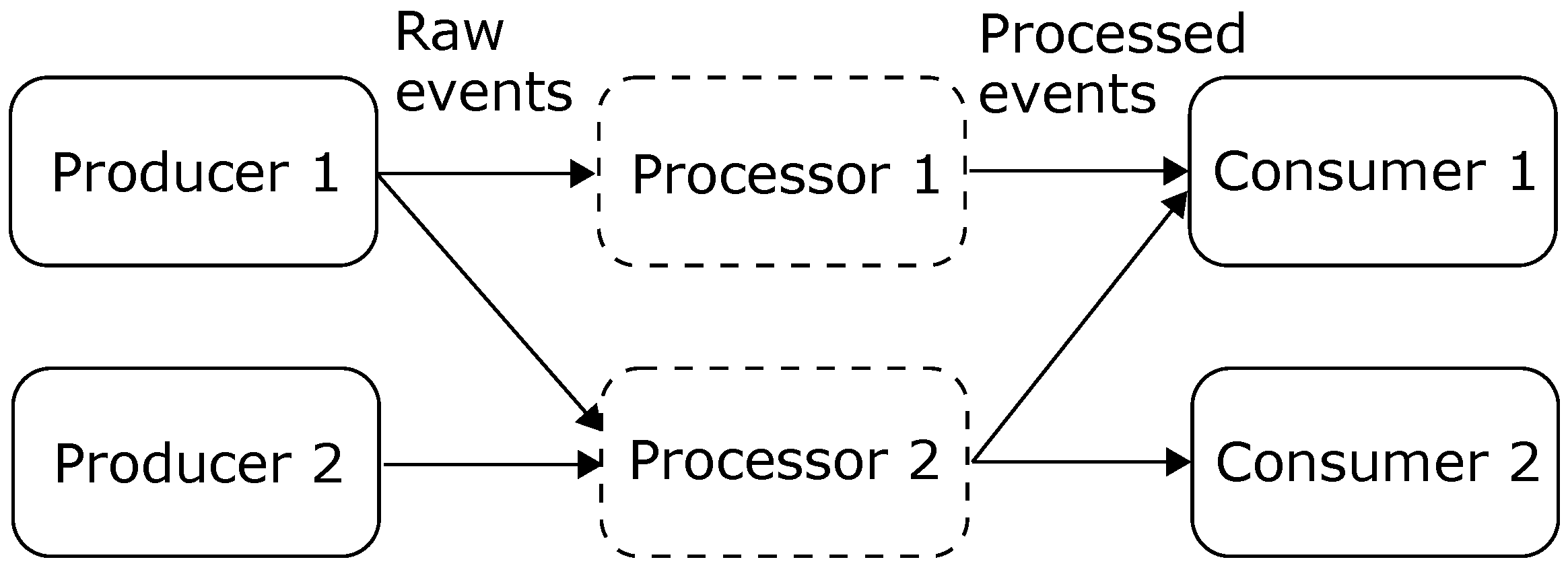
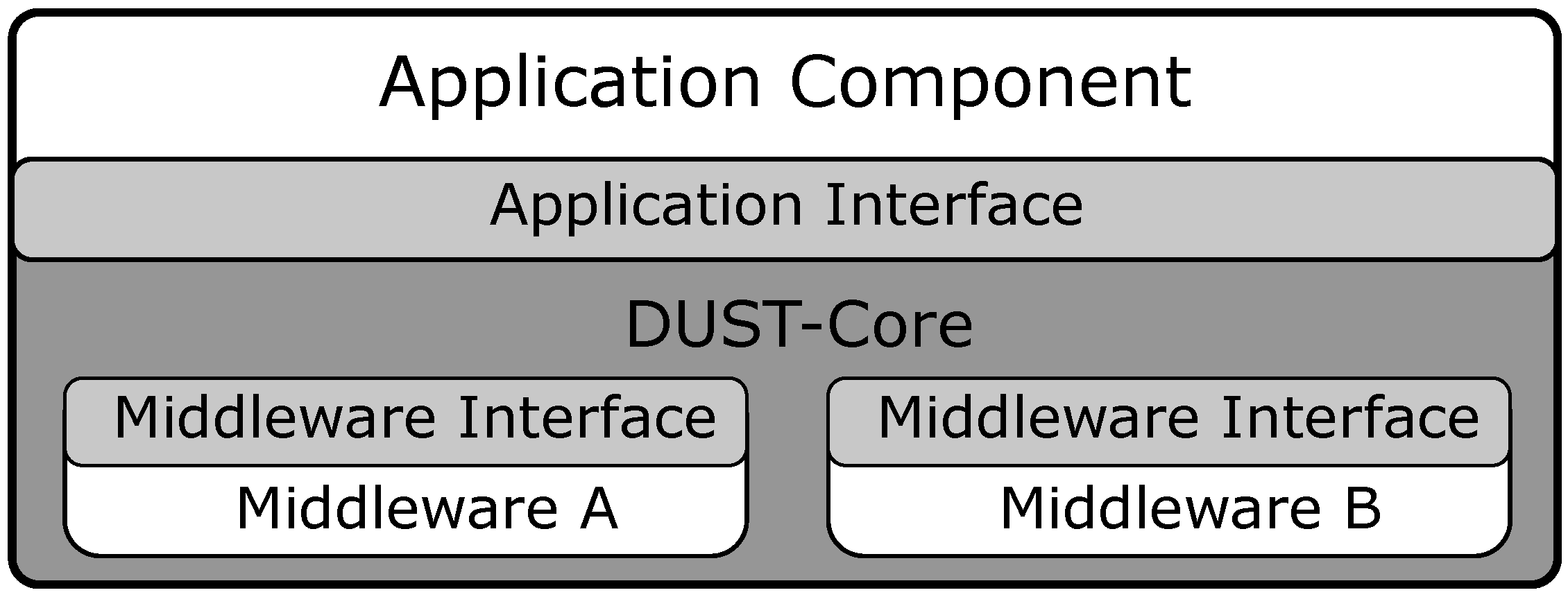
3. DUST Core for Event Streaming

The DUST-Core library implements the common functionality that is required for every streaming component (see Figure 1). This includes functionality such as event-streaming and configuration of the application component but does not include the functionality of the dynamic placement of application components. The dynamic placement is implemented in the DUST Coordinator which is described in Section 4. The DUST-Core architecture (see Figure 2) is divided into three main software modules. The first software module is the application interface which is designed to create the required abstraction to migrate application components and to change the middleware during runtime (e.g., use shared memory when application components are on the same physical device). The second module is the definition of the middleware implementation and requirements for event-streaming. The last software module is the DUST Core, which implements the functionality such as communication with the coordinator, message batching, etc. These software modules are described in the following subsections.

3.1. Application Interface

The first software module within the DUST Core is the Application interface. The design of this interface defines what can be optimized by the coordinator during runtime of the application component. The DUST framework uses the object-oriented programming paradigm to define the software structure. Every application will extend an abstract application component object. This extended object is used by the application to define the application callback functions, present DUST with the correct configuration file and allow the application to call the publish function. The structure of the events between the application components and between the application and the DUST Core is defined by the DUST-Messages. The DUST Core supports unprocessed event from a source device and events from a processor with a more complex data structure. These data-structures can be defined on the application level and are serialized to bytes. These bytes are stored in the payload field of the DUST Message. The DUST-messages data structure is defined as shown in Table 1. The DUST Core will add meta information to the DUST Message like a message id, a time stamp and source id. Because DUST is a publish/subscribe-based platform, the application can choose which application components will receive this event by selecting the topic on which the data is published.
This interface was developed to make the middleware and the execution location transparent to the application. This is a fundamental requirement when we need to change the middleware at runtime or move the application component to a different execution location which is a basic requirement for the DUST Coordinator (See Section 4). In the future, we plan to extend this interface to add new functionalities.

3.2. Middleware

The middleware allows the DUST Core to send the event messages between the application components. A variety of message protocols are available which can be used to stream these events. Every middleware has its own advantages and disadvantages. To support all these message protocols, the DUST Core makes abstraction of these protocols with a middleware interface. The conversion between the protocol implementation and the interface is handled by a middleware specific implementation. Every middleware specific implementation will also include a configuration parsing module to configure the middleware with the middleware specific functions. This makes that the DUST Core and by extension the application has no middleware specific code. This abstraction allows us to make the middleware transparent to the application and extend the amount of available message protocols.
The interface requires that the middleware can deliver the serialized message to other application components based on the publish subscribe paradigm. In this research, we used the messaging protocols MQTT [13], ZeroMQ [14] and DDS [15]. This abstraction allows the DUST Coordinator (see Section 4) to change the execution location of the application component without the need to change the software of the application component. The middleware abstraction will also allow us, in the future, to change to middleware based on the context (e.g., when application components run on the same device, we can change to a middleware that allows for shared memory communication). In the future, we can add additional middleware frameworks such as Kafka [16] to extend the amount of use cases that can be developed using DUST.

3.3. Core Functionality

The DUST Core will connect the application interface module with the middleware modules and offer the general functionality that every application component requires. The DUST Core offers functionality that is available over every message protocol within DUST.
The first functionality DUST offers is event message batching. The goal of batching is to group messages and send them together to minimize the impact on the network. This is important when a lot of small messages are being sent as in an IoT environment. The disadvantage of this approach is that some message need to wait before they are being sent. The DUST Core allows the user to configure the size of the batch before they are being send.
The next functionality the DUST Core offers is that it allows the coordinator to change the middleware during runtime to optimize the distributed resource consumption. Changing the middleware during runtime increases the chance that a message gets lost while the system is in transition. To minimize this problem, the DUST Core will implement a basic QoS level. The DUST Core will add an ID to every message (see Table 1). This ID is used to validate which messages are missing at the receiver side. When a message is missing, the DUST Core will notify the application which messages are missing. This is an important feature when we move application components and cannot guarantee that messages will arrive. The final QoS that is achieved by using the DUST Core will depend on the used middleware in combination with the added QoS that is built on top of the middleware. The QoS of the middleware can be adapted in the configuration or in the middleware specific implementation.
The DUST-Core library also implements the behavior required for the component monitoring. The library makes measurements such as CPU usage, RAM usage, and the number of messages sent between application components. These measurements are sent to the DUST Coordinator to be used in the distributed resource optimization process. The communication between the coordinator is also used to send commands from the coordinator to the application component such as a middleware change or a request to stop the process.

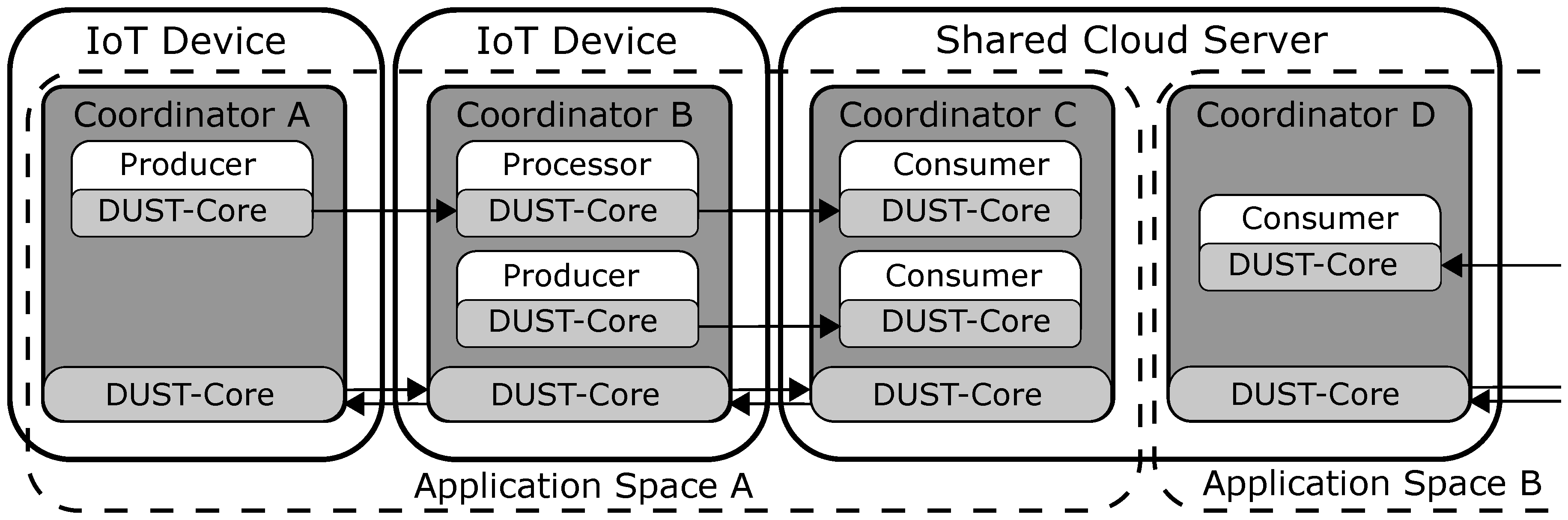
4. DUST Coordinator for Distributed Resource Optimization

The goal of the DUST Coordinator is to monitor every device and adapt the execution location of the application components to minimize the resource consumption. The DUST Coordinator is built on top of the DUST Core and requires that every application component uses the DUST-Core library to stream events. In this section, we will discuss the DUST Coordinator design and the required system architecture to optimize the distributed resource consumption.

4.1. DUST Coordinator System Architecture

The DUST system architecture uses multiple devices (e.g., IoT devices, fog devices and cloud servers) that will cooperate to execute the application graph. The DUST system architecture is shown in Figure 3. The group of devices that help to execute a certain application graph work in the same application space. Every device that is in an application space is required to run a DUST Coordinator. The DUST Coordinators that are in the same application space communicate with each other to optimize the distributed resources consumption. DUST Coordinators that are in a different application spaces do not communicate (e.g., limit the number of coordinators to the coordinators in a single smart home and one cloud instance). Certain devices work in multiple application spaces (e.g., a cloud server) and require a DUST Coordinator for every application space.
The DUST Coordinator is responsible to start, stop, and monitor every application component that runs on that device. The coordinators will communicate with the coordinators in the same application space to optimize the distributed resource consumption. The communication between the coordinators is implemented by the DUST-Core library (see Section 3). The DUST Coordinators are currently only able to move stateless application components because the DUST Core is currently not able to move states from one device to another.

4.2. Contract Net Protocol for Application Component Distribution

The DUST Coordinators will attempt to optimize the distributed resource consumption by changing the execution location of the application components. To determine where the application component will be executed, the coordinators will use an adapted version of the Contract Net Protocol (CNET) [17,18]. This is a method from the multi-agent research domain. The idea of the CNET protocol is to create an auction in which every DUST Coordinator will make an offer for a certain application component. The agent that can make the highest offer, will execute the application component. The CNET protocol contains multiple phases which are described below.
  • Organizer auction In the first phase, every coordinator that detects that an application component can be moved to another device (only processing components are allowed to move) will make a random offer to become the next organizer. The coordinator that can make the highest offer will be the organizer for the next phase. Every offer of the coordinator is a random value to ensure that every coordinator has the same chance to become the next organizer. The offer is sent to every coordinator which will compare the offer with other values it received. Once a coordinator receives an offer that is higher than every previous offer, the coordinator will response with a vote.
  • Organizer announcement The coordinator that received a vote from all the coordinators will become the organizer for the next phase. Once a coordinator receives a vote from every coordinator, it means that every coordinator received the offer and has determined that this offer is the highest. The organizer will respond with an announcement message and will initialize the next phase. In case that no coordinator has received a vote from every coordinator, it means that messages where lost during the auction and the auction will be reset after a certain timeout and the coordinators will restart from the first phase.
  • Task announcement In this phase, the organizer will organize a new auction to determine the execution location of an application component that is running on its device. The organizer will do this by sending a task announcement message to every coordinator which contains the application component requirements. The application component requirements are defined by the application components.
  • Task bidding In the task bidding phase, every coordinator will create an offer of the application components based on its requirements and based on the requirements of the application component that are running on the device of the coordinator. This offer is created with a cost function (see Section 4.3) that represents how the coordinator evaluates the capabilities of the device.
  • Task awarding The organizer will receive an offer from every coordinator and will determine the device which generates the highest offer based on the cost function. In this state of the algorithm, a new configuration will be sent to all the coordinators to update the middleware settings to support the new execution location and start the application component on the new execution location.
  • Organizer release Once the organizer finishes the auctions for the application components, it will release the organizer state by sending an organizer release message to every coordinator. This will trigger the first phase in every coordinator and the process repeats.

4.3. Cost-Function

The coordinators will evaluate the current state of the device and the requirements of the application component with the cost function to create an offer for an application component (see Section 4.2). This offer is used in the CNET algorithm. Sharif et al. [19] describe an equation (see Equation (1)) which can be used to estimate the total resource consumption and map these Key Performance Indicators (KPIs) to a total system cost. Their equation uses KPIs such as CPU usage or network usage. These KPIs are multiplied with a weight w i j which represent the importance of a certain KPI. When we add every weighted KPI of every application component and for every device, we achieve the total distributed resource consumption.
C = i = 1 # C o m p o n e n t s j = 1 # K P I w i j C i j
To calculate a weighted offer for a single application component, we adapt Equation (1) by using the inverse cost for every KPI. This calculation is carried out in Equation (2).
O f f e r = j = 1 # K P I 1 w j C j
In this research, we focused on the following KPIs: CPU usage, and the amount of network communication between application components. For every KPI, the weight w is determined empirically. In future research, we could take more KPIs into account; examples are memory usage, energy consumption, and response time. Another way to create an offer for a device is to take the execution cost of a real-world application component into account, which can also be based on the aforementioned KPIs.

5. Experiments

To validate the functionality of the DUST Coordinator, we perform several experiments to determine the capabilities to optimize the resource use of the application components. Therefore, we need to define KPI’s that allow us to quantitatively compare the optimizations that the DUST Coordinators had made. For this experiment, the following KPIs are chosen:
  • The CPU usage
  • The network usage
  • The number of received messages
The CPU and Network usage are very similar to the KPIs used to calculate the offer of a coordinator. The last KPI is added to the list to verify if the chain of application components can process the number of messages. A drop in the number of received messages indicates that the device was not able to process all messages of the application components. Each experiment had a runtime of 15 min for every use case. This provided the system enough time to stabilize and migrate application components to other devices by the DUST Coordinator if needed. For each use case, we applied a different configuration to have a wider coverage of various setups.

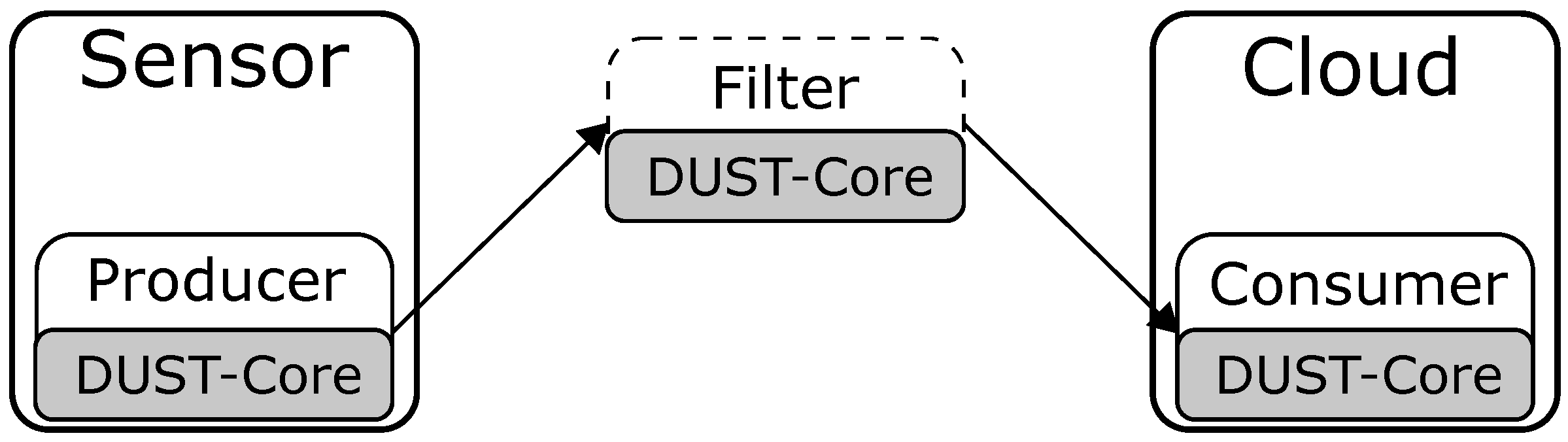
5.1. Use Case 1: Sensor to Cloud Streaming

The first use case is a configuration of a sensor node that streams events to the cloud, as shown in Figure 4. The producer component generates more excessive data than needed by the consumer. Therefore, a filter is placed between the producer and consumer. The filter performs a decimation of two (i.e., only one message out of two will be passed through). The producer and consumer components are not interchangeable between devices as the data is generated in the sensor node and the events are stored in the cloud node. However, the filter component can be placed on both nodes. The task of the DUST Coordinators is to find the optimal placement of the filter component on one of the nodes within the network. The hardware of the sensor is a Raspberry Pi 3 B+ with only a single core enabled. The cloud server uses an Intel i7-7700HQ processor.
For the first experiment, we configured the sensor node to produce 100 messages per second. In Table 2, the results of four different runs are shown to determine the optimal placement of the filter component and observe the behavior of the DUST Coordinators with this configuration. The first two runs examine the performance of the system when the filter component is placed consecutively on the sensor and cloud node without being managed by the DUST Coordinators. The latter experiments indicate that the DUST Coordinators will choose the place the filter component on the sensor node to reduce the network usage. The time to migrate a component between the nodes can vary as the offer to become the organizer is determined randomly.
For the second experiment, we increased the number of messages to the point where the sensor is unable to run the producer and filter component. The results in Table 3 show for the first two experiments that the system can deliver more messages to the consumer component when the filter component is placed on the cloud node. When the DUST framework manages the setup, we see that the DUST Coordinators will move the filter to the cloud to increase the throughput of the entire system.

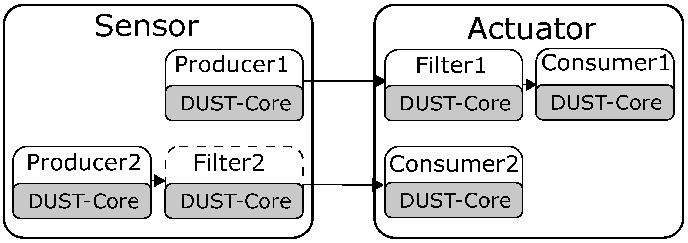
5.2. Use Case 2: Fog Computing

The second use case covers the optimization problem of multiple edge devices that can run multiple application components. Figure 5 shows the configuration of this experiment. The two sensors on the left will send data to the processor component in the middle. The processed data is then sent to the actuator on the right, which performs an action with the data. An average of every 3000 samples of the first sensor is also sent to the cloud though, as shown in the top half of the figure. The Sensor 1 and actuator components are executed on a Raspberry Pi 3 B+ with only a single core enabled. The Sensor 2 component is placed on a different Raspberry Pi 3 B+ with all its four cores enabled. The cloud node runs on an Intel i7-7700HQ processor.
As a reference, we locked the software components to fixed devices as a reference for the performance. The results without optimizations are shown in the first four rows of Table 4. We observe a high CPU usage on the actuator node while there are still computational resources available on other nodes. Additionally, the network load of the Cloud node is very high which we ultimately want to avoid as this connection often is more expensive. When the same configuration is managed by the DUST framework, we notice that the DUST Coordinators place the Processor and Average Application component to the actuator node as shown in the last four rows of Table 4. The actuator node has more computational resources. By migrating the blocks to the actuator node, the network usage of the cloud node is significantly reduced, and the CPU load of the actuator and Sensor 1 node is minimized.

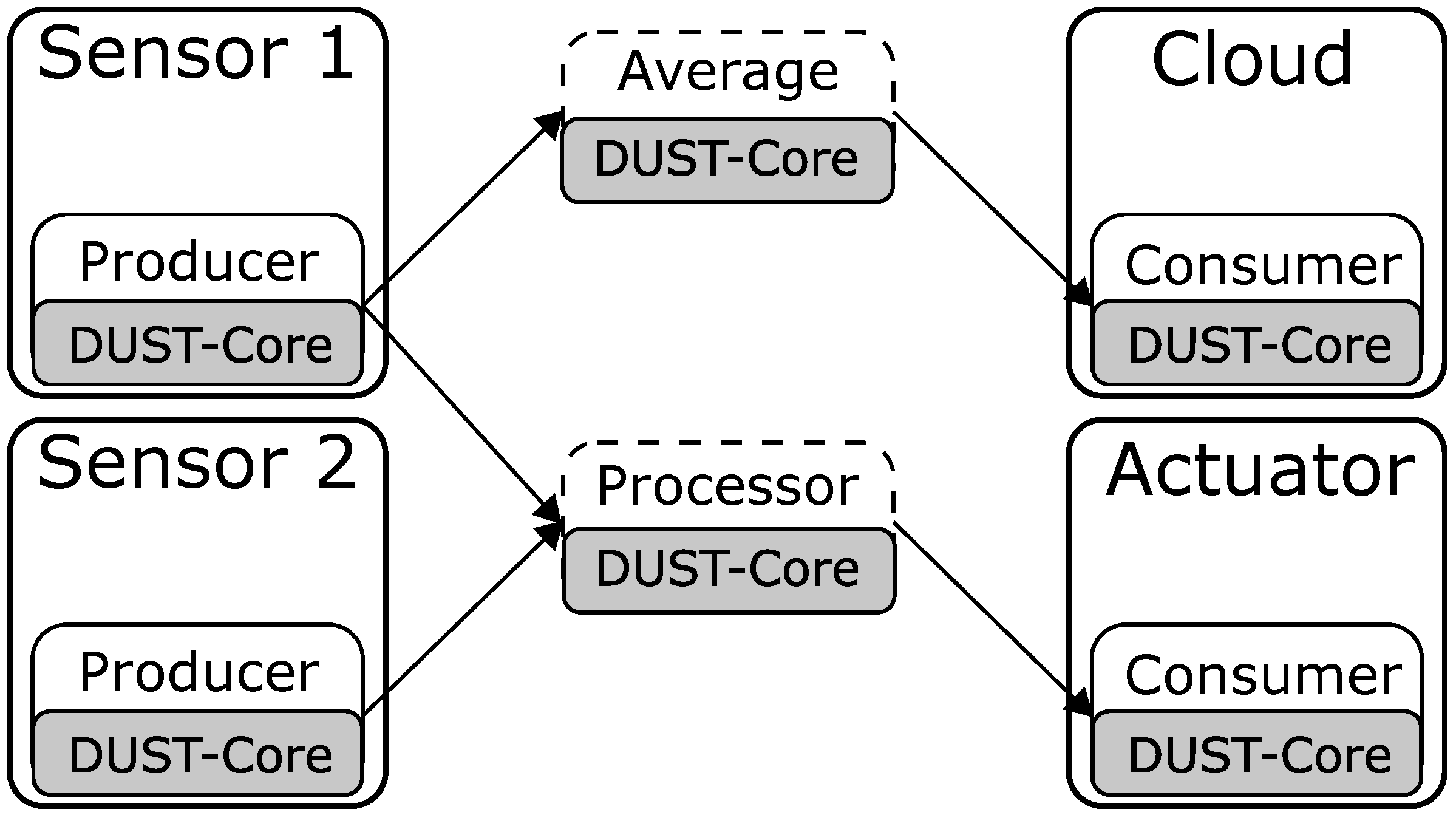
5.3. Use Case 3: Global Optimisations

The final use case shows that the current auction implementation of the DUST Coordinators is not always able to optimize the resource consumption to global minima. Figure 6 shows the configuration of this experiment. The sensor is sending two event streams to the actuator. This data is first filtered before sending it to the corresponding consumer component. Producer 1 will send 200 messages per second while producer 2 only send 100 messages per second. The sensor and actuator node are only allowed to run 3 different components at the same time, due to limited computational resources. Both nodes are executed on two Raspberry Pi 3 B+ with only a single core enabled.
Table 5 is a summary of the experiment results. The network usage shows to be the most optimal in the first two experiments when Filter 1 is placed on the sensor node and Filter 2 on the actuator node. The last experiment however shows that the DUST Coordinator was not able to migrate the components as only one component can be moved at a time. These results show that the DUST Coordinators cannot always find the global minima in resource consumption.

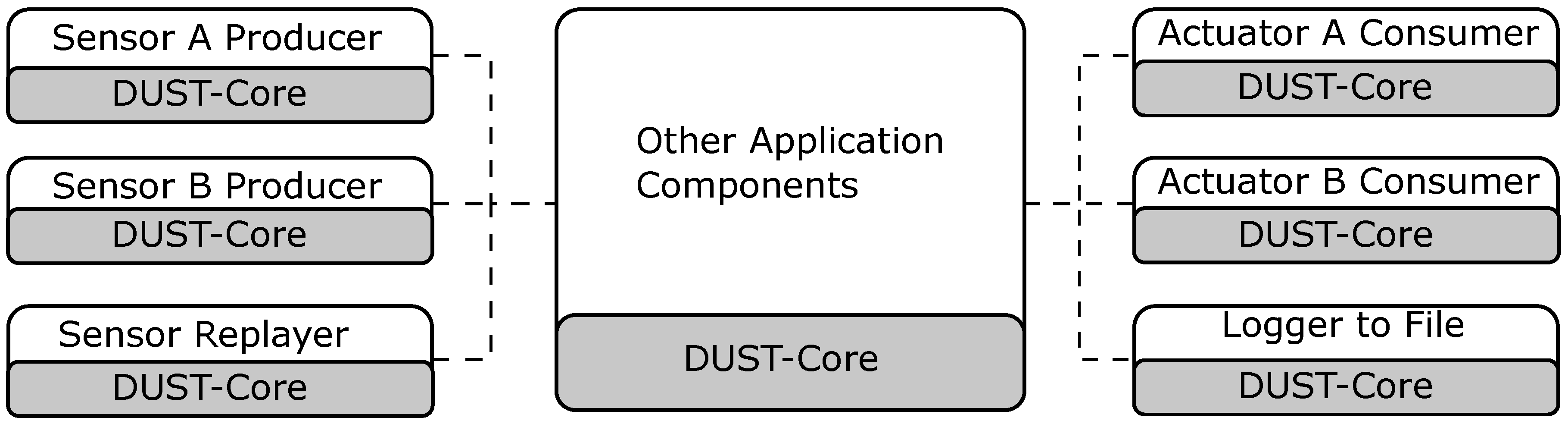
6. Platform Transparency Using Dust: A Connected Driving Use Case

The experiments in Section 5 focusses on the distributed resource distribution using the DUST Coordinators. In this section, we describe a connected driving use case we developed using the DUST-Core. We chose to discuss this use case to highlight the advantages and design considerations when using the DUST-Core without the DUST Coordinators to make the platform transparent to the application components.
In the future, cars will use communication technologies to share useful information with other cars. For example, when a car detects an obstacle on the highway, we need to share this information with other vehicles to improve the safety on the road. Marquez-Barja et al. [20] describe the Smart Highway project in which we are developing a testbed for Vehicle-to-everything (V2X) communication. We do this by installing communication equipment on the highway and by creating an Onboard Unit (OBU). The OBU is capable of sensor processing and can use communication equipment within the vehicle. In this use case, we will focus on the development of the OBU.
A big requirement when we were developing the OBU was that the system needs to be very flexible because it will be used within a Smart Highway testbed. This means that the software for the OBU needs to be able to handle different kind of sensor hardware, actuator hardware, communication hardware, and processing hardware. This large flexibility in hardware forms a challenge to develop the standardized software which is required for the testbed. In the next subsections, we will describe how we used the DUST-Core to create a platform transparent software architecture to create a flexible testbed.

6.1. Application Component Architecture for Hardware Transparency

The OBU-software is based on the event-processing model (as described by Moxey et al. [4]) and implemented using the DUST-Core. We have no DUST Coordinators in the OBU because we need a fixed execution location for every application component (although this could be a future research direction). As discussed in the previous subsection, the software architecture needs to be able to handle large hardware changes with a minimal change in software. To handle this change in hardware, we construct applications with an application graph of multiple application components that stream events to each other. This software architecture allows us to create a strong hardware flexibility without changing the entire application (the processing components are reusable). When we change the event producer of consumer (e.g., the sensor hardware, actuator hardware, or the communication hardware), we only need to change the event producer and/or event consumer that is relevant and reuse the processing components. Figure 7 shows that we can implement multiple producers to read the information from the sensor and publish it in the same data format. By doing so, the hardware change is transparent to the other application components. Additionally, to changing the hardware, we can also replay stored sensor data in the same data format as the original sensor. This allows developers to stub the original sensors without the need for the physical sensors. Figure 7 also shows that the receiving actuators can also be interchanged if we write a new consumer application component to control the actuator with the same data format.
When we change the execution location of a processing application component to a different processing unit, we only need to change the configuration of the application components. This change in configuration will change the flow of events to include the different processing unit in the application execution graph without any change in the application components. This software architecture allows hardware flexibility without the need to restructure the entire application.

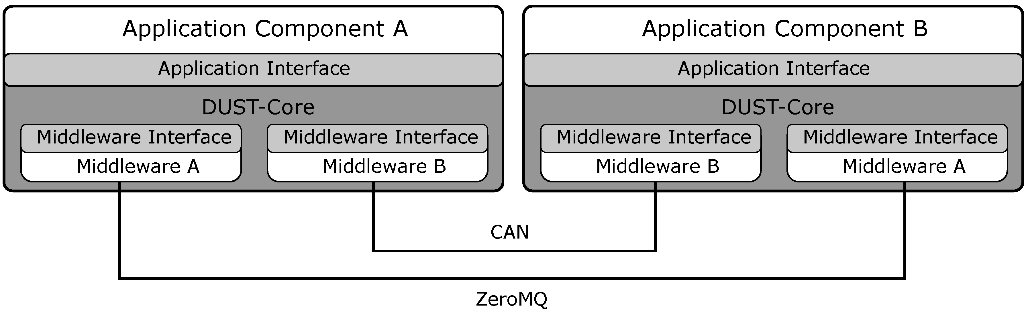
6.2. Middleware Transparency

In the previous section, we described the importance of hardware transparency in the development of the OBU architecture. Next to the hardware transparency, we are also able to create the middleware transparency by using the DUST-Core as a middleware platform. The middleware interface within DUST allows us to change the middleware without the need to change the application components in the application graph. This is also a key requirement within the development of the OBU because when an original equipment manufacturer (OEM) will implement software from the Smart Highway testbed to a real vehicle, they will not use a middleware such as ZeroMQ or MQTT but will send event message on a standard from the automotive industry (e.g., Controller Area Network (CAN), Flexray or Automotive Ethernet). This change in middleware is possible because of the middleware interface in the DUST-Core. In the case that we want to send message events over a CAN-interface, we create a new middleware object in the DUST-Core which is able to send and receive message with a CAN-interface (see Figure 8). The application components do not need to be changed although there is a large change in communication middleware between the application components.

6.3. Platform Transparency

The transparency of hardware and the transparency of middleware that is possible by using the abstractions within the DUST-Core creates the flexibility we required for the Smart Highway testbed. The combination of the hardware transparency and middleware transparency allows us to create a platform transparent software architecture. The described architecture of an event-streaming model in combination of an abstract middleware interface, which is created by using the DUST-Core, creates a platform transparency that allows for a large reusability of application components. We believe that this architecture is usable in a wide range of streaming applications (e.g., IoT applications) to create the same software reusability even when the middleware is changed.

7. Conclusions

In this paper, we demonstrated how we can create application components that can communicate with each other using an abstract middleware interface that is implemented in the DUST Core. The DUST Coordinators can then use these application components to optimize the distributed resource consumption. In our experiments, we showed that the coordinators can optimize the resource consumption but are only able to find local minima in distributed resource consumption. Finally, we demonstrated a real-world example of a system architecture that uses the DUST Core which creates platform transparency and enables software reusability.
Future research could investigate a combination of a global search algorithm with the Contract Net Protocol. This would allow the global method, which is computationally complex, to find an optimal placement and the less computationally complex Contract Net Protocol to make changes during the calculations of the global method. Another research direction is the research on device failure because edge and fog devices are more susceptible to failures than cloud infrastructure. One method would be to recover from a device failure and move the application components towards another execution device to continue the application execution. Another method would be to try to predict when a device will fail and move the application components from that device before the device has failed (e.g., a device with a low battery). Because of the computational peaks that arise from event processing, the techniques described by Teranishi et al. [8] could be combined with the Contract Net Protocol and a global search algorithm.

Author Contributions

Conceptualization, S.V., J.H., T.H., S.B., R.E., M.S., S.M. and P.H.; methodology, S.V., S.M., P.H.; software, S.V., J.H., T.H., S.B., R.E. and M.S.; validation, S.V. and J.H.; formal analysis, S.V.; investigation, S.V., J.H., T.H., S.B. and R.E.; resources, S.V.; data curation, S.V.; writing—original draft preparation, S.V.; writing—review and editing, S.V., J.H., T.H., R.E., S.M. and P.H.; visualization, S.V.; supervision, S.M. and P.H.; project administration, S.M. and P.H.; funding acquisition, S.M. and P.H.

Funding

This research was funded by the Smart Highway project from Agentschap Innoveren en Ondernemen (VLAIO) grant number HBC.2017.0612.

Conflicts of Interest

The authors declare no conflict of interest. The funders had no role in the design of the study; in the collection, analyses, or interpretation of data; in the writing of the manuscript, or in the decision to publish the results.

Abbreviations

The following abbreviations are used in this manuscript:
CANController Area Network
CNETContract Net Protocol
DUSTDistributed Uniform Streaming
IoTInternet of Things
KPIKey Performance Indicator
OBUOnboard Unit
OEMoriginal equipment manufacturer
V2XVehicle-to-everything
QoSQuality of Service

References

  1. Atzori, L.; Iera, A.; Morabito, G. The internet of things: A survey. Comput. Netw. 2010, 54, 2787–2805. [Google Scholar] [CrossRef]
  2. Gubbi, J.; Buyya, R.; Marusic, S.; Palaniswami, M. Internet of Things (IoT): A vision, architectural elements, and future directions. Future Gener. Comput. Syst. 2013, 29, 1645–1660. [Google Scholar] [CrossRef] [Green Version]
  3. Armbrust, M.; Fox, A.; Griffith, R.; Joseph, A.D.; Katz, R.; Konwinski, A.; Lee, G.; Patterson, D.A.; Rabkin, A.; Stoica, I.; et al. A view of cloud computing. Commun. ACM 2010, 53, 50–58. [Google Scholar] [CrossRef] [Green Version]
  4. Moxey, C.; Edwards, M.; Etzion, O.; Ibrahim, M.; Iyer, S.; Lalanne, H.; Monze, M.; Peters, M.; Rabinovich, Y.; Sharon, G.; et al. A Conceptual Model for Event Processing Systems. IBM Redguide Publication. 2010. Available online: http://www.redbooks.ibm.com/redpapers/pdfs/redp4642.pdf (accessed on 17 July 2018).
  5. Vanneste, S.; de Hoog, J.; Huybrechts, T.; Bosmans, S.; Sharif, M.; Mercelis, S.; Hellinckx, P. Distributed Uniform Streaming Framework: Towards an Elastic Fog Computing Platform for Event Stream Processing. In Advances on P2P, Parallel, Grid, Cloud and Internet Computing, 3PGCIC 2018; Xhafa, F., Leu, F.Y., Ficco, M., Yang, C.T., Eds.; Lecture Notes on Data Engineering and Communications Technologies; Springer: Cham, Switzerland, 2019; Volume 24. [Google Scholar]
  6. Habak, K.; Ammar, M.; Harras, K.A.; Zegura, E. Femto clouds: Leveraging mobile devices to provide cloud service at the edge. In Proceedings of the 2015 IEEE 8th International Conference on Cloud Computing (CLOUD), New York, NY, USA, 27 June–2 July 2015; pp. 9–16. [Google Scholar]
  7. Pan, J.; McElhannon, J. Future edge cloud and edge computing for internet of things applications. IEEE Internet Things J. 2018, 5, 439–449. [Google Scholar] [CrossRef]
  8. Teranishi, Y.; Kimata, T.; Yamanaka, H.; Kawai, E.; Harai, H. Dynamic Data Flow Processing in Edge Computing Environments. In Proceedings of the 2017 IEEE 41st Annual Computer Software and Applications Conference (COMPSAC), Turin, Italy, 4–8 July 2017; Volume 1, pp. 935–944. [Google Scholar]
  9. Hummer, W.; Satzger, B.; Dustdar, S. Elastic Stream Processing in the Cloud. Wiley Interdiscip. Rev. Data Min. Knowl. Discov. 2013, 3, 333–345. [Google Scholar] [CrossRef]
  10. Eyckerman, R.; Sharif, M.; Mercelis, S.; Hellinckx, P. Context-Aware Distribution in Constrained IoT Environments. In Proceedings of the International Conference on P2P, Parallel, Grid, Cloud and Internet Computing, Taichung, Taiwan, 27–29 October 2018; Springer: Cham, Switzerland, 2018; pp. 437–446. [Google Scholar]
  11. Fed4Fire. Federation For Fire Plus. Available online: https://www.fed4fire.eu/ (accessed on 5 July 2019).
  12. Byers, C. Architectural Imperatives for Fog Computing: Use Cases, Requirements, and Architectural Techniques for Fog-Enabled IoT Networks. IEEE Commun. Mag. 2017, 55, 14–20. [Google Scholar] [CrossRef]
  13. Paho-mqtt. Eclipse Paho MQTT Python Client Library. Available online: https://pypi.org/project/paho-mqtt/ (accessed on 16 May 2019).
  14. ZeroMQ. ZeroMQ Distributed Messaging. Available online: http://zeromq.org (accessed on 16 May 2019).
  15. OpenSplice DDS. Adlink OpenSplice DDS Community Edition. Available online: http://www.prismtech.com/dds-community/software-downloads (accessed on 16 May 2019).
  16. Kreps, J.; Narkhede, N.; Rao, J. Kafka: A distributed messaging system for log processing. In Proceedings of the NetDB’11, Athens, Greece, 12 June 2011; pp. 1–7. [Google Scholar]
  17. Smith, R.G. The contract net protocol: High-level communication and control in a distributed problem solver. IEEE Trans. Comput. 1980, 12, 1104–1113. [Google Scholar] [CrossRef]
  18. Wooldridge, M. An Introduction to MultiAgent Systems; Wiley: Chichester, UK, 2009; ISBN 978-0470519462. [Google Scholar]
  19. Sharif, M.; Mercelis, S.; Hellinckx, P. Context-Aware Optimization of Distributed Resources in Internet of Things Using Key Performance Indicators. In Proceedings of the International Conference on P2P, Parallel, Grid, Cloud and Internet Computing, Barcelona, Spain, 8–10 November 2017; Springer: Cham, Switzerland, 2017; pp. 733–742. [Google Scholar]
  20. Marquez-Barja, J.; Lannoo, B.; Naudtsy, D.; Braem, B.; Maglogiannisy, V.; Donato, C.; Mercelis, S.; Berkvens, R.; Hellinckx, P.; Weyn, M.; et al. Smart Highway: ITS-G5 and C2VX based testbed for vehicular communications in real environments enhanced by edge/cloud technologies. In Proceedings of the 28th European Conference on Networks and Communications (EuCNC 2019), Valencia, Spain, 18–21 June 2019. [Google Scholar]
Figure 1. The event-streaming graph from producers towards the consumers.
Futureinternet 11 00158 g001
Figure 2. The common DUST-Core architecture.
Futureinternet 11 00158 g002
Figure 3. The DUST system architecture using the DUST Core and the DUST Coordinators with multiple application spaces.
Futureinternet 11 00158 g003
Figure 4. The streaming configuration from sensor to cloud. The filter can be placed on the sensor or on the cloud depending on the devices and the applications.
Futureinternet 11 00158 g004
Figure 5. The streaming configuration from sensors to the actuator. The events from sensor 1 are also averaged over time and send to the cloud.
Futureinternet 11 00158 g005
Figure 6. The streaming configuration from sensor to actuator. The filters can be placed on the sensor or on the actuator.
Futureinternet 11 00158 g006
Figure 7. The hardware is transparent to the processing application components.
Futureinternet 11 00158 g007
Figure 8. The middleware is transparent to the application components.
Futureinternet 11 00158 g008
Table 1. The DUST Message data structure.
TypeDescription
IDuint64A field that is incremented with one to create a unique number for every message.
Typeuint64An optional field in which the application can define the type of message that is send in the payload.
Timestampuint64 + uint32The UTC-time of sending an event message.
KeybytesAn optional field to indicate the key which can be used by the application.
PayloadbytesThe payload of the message. The application can define the structure of the payload.
Source IDstringThe unique string that defines the source application component of the message.
Table 2. Network optimization of use case 1.
Managed byFilter beforeFilter afterCPU Usage ofMessagesTotal Network
DUSTMigrationMigrationSensor/Cloud (%)ReceivedUsage (MB)
SensorSensor29.2/1.144,4205.20
CloudCloud16.3/2.044,5607.44
SensorSensor29.2/1.544,4605.48
CloudSensor29.2/1.943,9405.63
Table 3. CPU optimization of use case 1.
Managed byFilter beforeFilter afterCPU Usage ofMessagesTotal Network
DUSTMigrationMigrationSensor/Cloud (%)ReceivedUsage (MB)
SensorSensor89.1 a /2.6192,04012.81
CloudCloud89.7 a /13.2409,96043.87
SensorCloud89.3 a /5.3326,34034.28
CloudCloud86.9 a /5.8380,06040.90
a The remaining CPU cycles are used by kernel.
Table 4. Fog computing results of use case 2.
Managed byDeviceRunning ComponentsCPU UsageMessagesDevice Network
DUST on the Deviceof Device (%)ReceivedUsage (MB)
Sensor 1Source59.9n.a.33.16
Sensor 2Source19.2n.a.11.54
ActuatorProcessor, Sink77.9237,04525.18
CloudAverage, Sink37.88820.56
Sensor 1Source61.2n.a.33.97
Sensor 2Source, Average,191.5n.a.49.90
Processor
ActuatorSink57.1291,62025.75
CloudSink20.3878.240
Table 5. The global optimisation results.
Managed byFilter1/2 StartFilter1/2 EndCPU Usage ofMessagesTotal Network
DUSTDeviceDeviceSensor/Actuator (%)ReceivedUsage (MB)
Actuator/SensorActuator/Sensor63.4/64.3133,27038.40
Sensor/ActuatorSensor/Actuator81.6/46.2133,13032.60
Actuator/SensorActuator/Sensor64.5/63.4132,71839.00

