Article

Autoplant—Autonomous Site Preparation and Tree Planting for a Sustainable Bioeconomy

1
Skogforsk, The Forestry Research Institute of Sweden, 751 83 Uppsala, Sweden
2
Department of Engineering Design, KTH-Swedish Royal Institute of Technology, 100 44 Stockholm, Sweden
3
Department of Engineering Science and Mathematics, Luleå University of Technology, 971 87 Luleå, Sweden
4
Bracke Forest AB, 843 31 Bräcke, Sweden
5
Södra, 351 89 Växjö, Sweden
6
Département de Génie Mécanique, Université Laval, Québec, QC G1V 0A6, Canada
7
Creative Optimization Sweden AB, 302 31 Halmstad, Sweden
8
Skogstekniska Klustret (The Swedish Cluster of Forest Technology), 907 29 Umeå, Sweden
*
Author to whom correspondence should be addressed.
Forests 2024, 15(2), 263; https://doi.org/10.3390/f15020263
Submission received: 21 December 2023 / Revised: 15 January 2024 / Accepted: 23 January 2024 / Published: 29 January 2024

Abstract

:
Sustainable forestry requires efficient regeneration methods to ensure that new forests are established quickly. In Sweden, 99% of the planting is manual, but finding labor for this arduous work is difficult. An autonomous scarifying and planting machine with high precision, low environmental impact, and a good work environment would meet the needs of the forest industry. For two years, a collaborative group of researchers, manufacturers, and users (forest companies) has worked together on developing and testing a new concept for autonomous forest regeneration (Autoplant). The concept comprises several subsystems, i.e., regeneration and route planning, autonomous driving (path planning), new technology for forest regeneration with minimal environmental impact, automatic plant management, crane motion planning, detection of planting spots, and follow-up. The subsystems were tested separately and integrated together during a field test at a clearcut. The concept shows great potential, especially from an environmental perspective, with significantly reduced soil disturbances, from approximately 50% (the area proportion of the area disturbed by disc trenching) to less than 3%. The Autoplant project highlights the challenges and opportunities related to future development, e.g., the relation between machine cost and operating speed, sensor robustness in response to vibrations and weather, and precision in detecting the size and type of obstacles during autonomous driving and planting.

1. Introduction

In the ongoing climate crisis, it is important to maximize carbon sequestration [1,2] and minimize greenhouse gas emissions in all parts of forestry to reach the goal of a sustainable bioeconomy. A major societal challenge is to maximize forest growth and carbon storage in standing forests [1,3] at the same time as more wood needs to be harvested to produce forest biomass for substituting fossil fuel products [4] or other products associated with high greenhouse gas emissions, such as cement [5]. Forest management methods need to be environmentally friendly and cost-efficient and offer a good work environment for forest workers. Ecologically, economically, and socially sustainable forestry methods, including high and value-creating growth through resource-efficient precision technology, are an important part of the solution. Efficient forest regeneration has the potential to provide rapid re-establishment and growth of seedlings to shorten the phase during which forest regeneration areas are carbon sources instead of carbon sinks [6,7,8].
Traditional mechanical site preparation methods, such as mounding and disc trenching [9,10,11], involve high energy consumption and impact a significant proportion of the soil in a regeneration area (17–70% of the total area of a clearcut [8]). The dominant tree species to be planted in northern Europe are Scots pine (Pinus sylvestris L.) and Norway spruce (Picea abies (L.) H. Karst.). From the perspective of the survival of these seedlings, a disturbed soil area proportion of 3% of the total area is necessary, ensuring that a seedling is surrounded by at least 20 cm of mineral soil to reduce pine weevil (Hylobius abietis (L.)) damage [12].
Currently, labor-intensive manual planting is difficult to source in northern Europe [13,14]. The shortage of labor has been a main driver for silvicultural technology development in boreal forestry since the mid-1960s, with renewed attempts during periods when the shortage has been more evident [15]. As workforce turnover increases, the quality of manual planting may decrease, as it takes time for manual planters to acquire the skills of selecting good planting spots while retaining a high level of productivity. Other drivers of silvicultural technology development, as summarized in [13], have been reductions in the use of herbicides, improvements in the work environment and planting quality, reductions in regeneration costs, and increases in productivity.
Internationally, there are several different commercial planting machines operating, especially within short-rotation plantation forestry, although manual planting still dominates, by far, worldwide [13]. Automation has been suggested as one way to increase productivity in mechanical planting [16]. In Brazil, a semi-autonomous planting machine with three heads was launched in 2019 [13]. However, the large eucalyptus fields in Brazil are very different from stony boreal forests, in which the forest floor is mainly intact and standing and fallen trees are left in the regeneration areas. Several projects have tested new technology in recent years, including automation and image analyses in planting machines. In Poland, a scientific–industrial consortium is developing a planting robot, RoboFoR [17,18]. In parallel with the Autoplant project, Södra (the forest owners’ association of southern Sweden) is developing its own planting machine, BraSatt [19]. In Sweden, several forestry companies have invested in making PlantmaX (a development of the Silva Nova [20]) smarter such that it avoids unsuitable planting spots by using image analysis [21].
To address several challenges related to forest regeneration, the collaborative project Autoplant was set up by nine organizations: the Forest Research Institute of Sweden (Skogforsk), Luleå University of Technology (LTU), the Swedish Royal Institute of Technology (KTH), the silvicultural technology company Bracke Forest AB, the Cluster of Forest Technology, three forest companies (SCA, Holmen, and Sveaskog), and one forest owners’ association (Södra). The project period was from February 2021 to February 2023.
The overall aim of the project was to address the societal challenges summarized as follows, using the methods shown in italics:
  • The Climate Challenge: Improving planting spots and seedling survival rates results in quicker establishment of new forests following harvesting, thereby reducing carbon dioxide emissions [6,7,8]. The increased precision in site preparation and planting further improves energy efficiency due to a much smaller area proportion of the soil being processed.
  • The Environmental Challenge: Precision site preparation and more precise regeneration planning significantly reduce the area proportion of soil disturbance by only affecting the area closest to the planted seedlings. This benefits environmental and cultural conservation (less damage to cultural remains), as well as other forest values, such as recreation, berry picking, and reindeer herding [22].
  • The Work Environment Challenge: Automation eliminates harmful whole-body vibrations associated with off-road driving, and a safer work environment is promoted.
  • The Workforce and Gender Equality Challenge: New work tasks and lighter workloads may attract new demographic groups to forest work. In the future, the remote handling of certain tasks could contribute to a better balance between work and family life.
The objective of the Autoplant project was to develop autonomous forest regeneration techniques adapted to boreal conditions and characterized by high precision, low environmental impact, and a favorable work environment, while retaining high productivity. The specific objective of the two-year project was to develop and test the different subproducts needed for the future system to work, integrate the subsystems, and demonstrate a fully autonomous site preparation and planting cycle in full scale and in real time at a forest regeneration area (clearcut) in central Sweden. The aim of this paper is to describe the different parts of the Autoplant concept and discuss the challenges and opportunities related to the future development of the complete system, as well as the different subsystems.

2. The Autoplant Concept

Autoplant is not a planting machine prototype but a research concept for developing key subsystems for enabling autonomous forest regeneration machines. The subsystems are described in different sections below and include the following: the brain of the machine—Mission Supervisor (Section 2.1); regeneration and route planning—Pathfinder (Section 2.2); autonomous navigation—Path Planning (Section 2.3); the terrain vehicle platform (Section 2.4); the Planter—new technology for forest regeneration (Section 2.5); the Crane Controller—motion planning and control of the crane (Section 2.7); and finally, detection of planting spots—the Planting Planner (Section 2.8).
A communication diagram of the different subsystems and how they interact, along with the main hardware components, is presented in Figure 1. The Mission Supervisor acts as the coordinator that instructs the main subsystems using ROS (Robot Operating System [23]) actions and services. Prior to the launching of the system, a global route is loaded as a file of coordinates from Pathfinder. In addition to the components shown in the diagram, three computer units run the different software components, mainly as ROS nodes. All three computers and the vehicle Programmable Logic Controller (PLC) are connected to a local ethernet network. An additional laptop allows the control and monitoring of the machine and connects to the machine network using Wi-Fi.

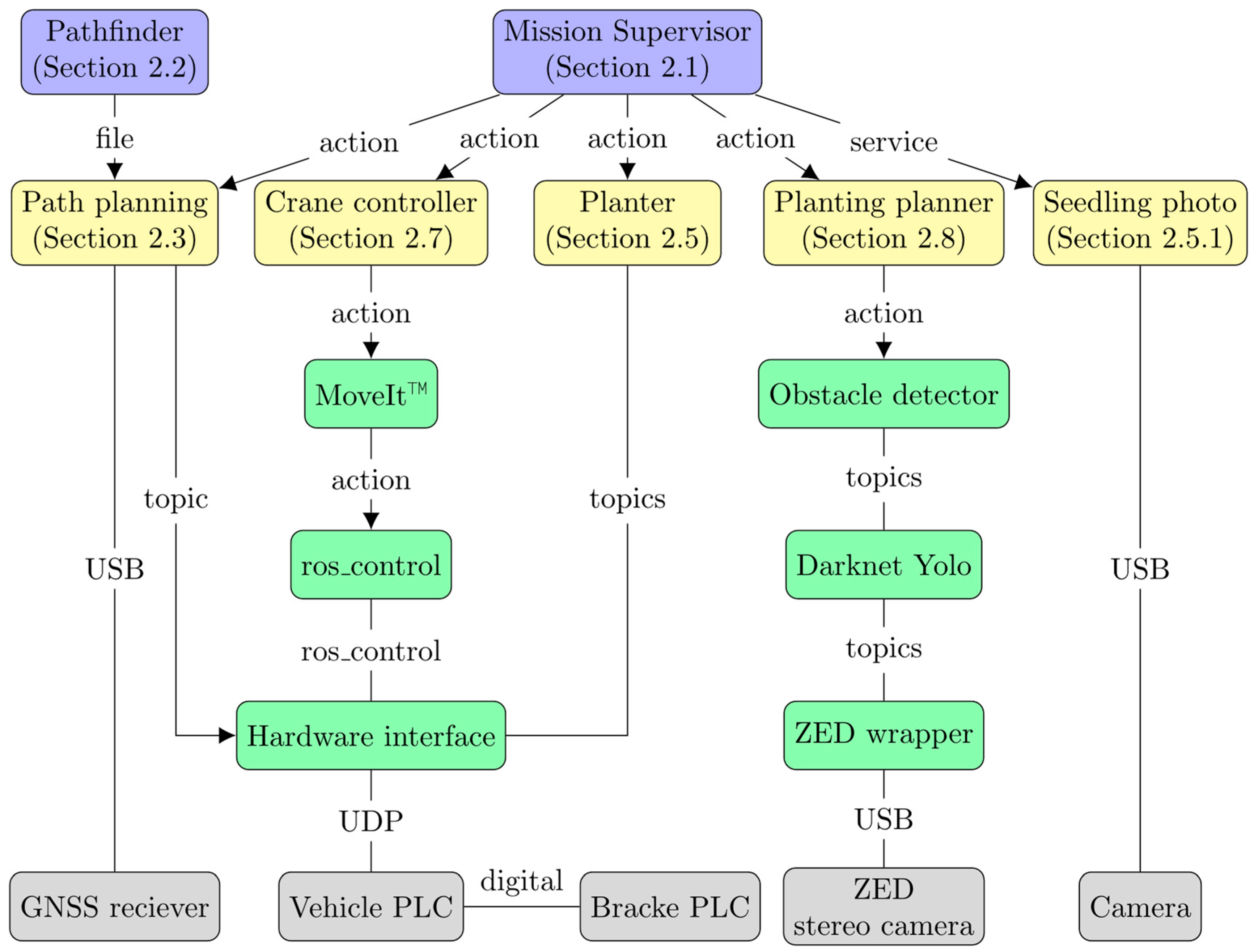
2.1. The Brain of the Machine—Mission Supervisor

The Mission Supervisor serves as the mission planner and is the primary controller of the machine. A detailed description of its function is presented in [24]. This system is structured hierarchically, comprising various subsystems, each tasked with managing a specific hardware system or function. The Mission Supervisor orchestrates the activities of these subsystems, dictating the actions to be executed and their timing.
The Mission Supervisor design is based on finite state machines—a control logic principle that facilitates complex behaviors through a defined set of states. The SMACH toolbox [25] was utilized within ROS to implement the Mission Supervisor as an ROS node. In the setup, most states in the Mission Supervisor correspond to specific actions. These actions, integral to the functioning of the machine, are listed in Table 1. The main operation path in automatic mode can be summarized as follows:
  • The Crane Controller performs TRANSPORT to place the crane in the transport position.
  • The Path Planner performs NEXT_POS, which makes a local path and autonomously moves the machine a predefined distance along the planned path. If the path has reached the final point, the execution goes to standby. Otherwise, the machine stops and initiates planting operations in this new staging area.
  • Now, the crane performs DOCK to place the crane in docking position. Meanwhile, the Planter performs TRANSFER to pick a seedling from the local storage.
  • When the crane is in position, the Planter performs DROP to load itself. Meanwhile, the Planting Planner performs PHOTO_WORKAREA followed by ADD_OBSTACLES to map the obstacles in the staging area.
  • The Planting Planner performs GET_POSITION to find a free position for planting. If no free position is found, the machine will restart at Step 1 and move to a new position.
  • The Crane Controller performs POSITION_ABOVE_SEEDLING followed by POSITION_ON GROUND to place the Planter on the ground using ground pressure sensing.
  • The Planter performs PLANT to scarify and plant the seedling.
  • The Crane Controller performs PHOTO_SEEDLING to place the crane above the plant to take a photo.
  • The Seedling Photo performs TAKE_PHOTO to take a photo of the planting spot.
  • The Planting Planner performs SAVE_SUCCESS, SAVE_FAIL_SCAR, SAVE_FAIL_GROUND, or SAVE_FAIL_CRANE depending on the outcome of the planting.
  • If the attempt failed, and the seedling is still intact, the Planting Planner loops back to Step 6 and performs GET_POSITION. However, if the planting was successful, the execution loops back to Step 3 to load a new seedling instead. This time around, there will be no new detection of obstacles in the staging area. All the planting attempts have already been saved based on the Planter’s location, and no visual identification is needed to localize the seedlings.
The flow of operations in the Mission Supervisor is dynamic, where the transition from a completed state can lead to various subsequent states, depending on the preceding outcomes. One strength of state machines is the methodology for describing and developing these types of processes in a structured way. Placing the code and logic for executing the actions corresponding to states within the individual subsystems keeps the Mission Supervisor at a manageable abstraction level. Each subsystem may encompass additional mechanisms for handling specific tasks, as further illustrated in Figure 1.

2.2. Pathfinder—Regeneration and Route Planning

Pathfinder is a decision support tool developed in the Autoplant project that suggests net area to plant, tree species, seedling density, and the global route for autonomous driving (Figure 2). It consists of two submodules, PlantP [26] and PathP [27], which are described briefly below.

2.2.1. PlantP

The PlantP module, which has been developed in an adjacent project [26], uses the harvested production (hpr) files to decide the net area for regeneration (Figure 2b, the gross area is the planned area for harvesting, Figure 2a). PlantP suggests tree species and seedling density based on the site index derived from the harvested trees. Forest data from the Swedish Forest Agency are used to identify areas with a priori low tree coverage (e.g., impediments). The Swedish National Road Database is used to separate regeneration areas from roads. A soil moisture index map from the Natural Land Cover Database [28] is used to exclude areas that are too wet or too dry, and parent material maps are used to exclude peat soils. The threshold values are based on inventory data from ~6000 sample plots throughout Sweden [26].

2.2.2. PathP

The output from PlantP (Figure 2c) is used as input to PathP together with a digital elevation model (DEM), forcing passages, additional NoGo areas (if present), and machine data. Here, a resolution of 1 m was used for the DEM. The machine data include working speed (default 1 m s−1) and width (here 6 m), extra time penalties for turns of different sharpnesses, critical slope where driving direction is significant (here ≥ 15°), and the seedling carrying capacity (here 1500). The reloading of seedlings is a manual task at the landing. As sharp turns are difficult both for autonomous terrain vehicles in unknown terrain and for large traditional scarifiers, the tool aims to minimize U-turns.
The solution approach is divided into several steps to find the routes: 1. The area is discretized into hexagons, where each hexagon has 10 m between its opposing sides (Figure 2d), each comprising a slope direction based on the DEM. 2. The slope of each hexagon is smoothed in relation to its neighbors. 3. Hexagons are connected to create groups of larger areas with the smoothed directions. Only certain directions are allowed if the slope is greater than a chosen threshold (here 15°). For all feasible and imposed directions, the longest possible path without turning is created. 4. Within each group of hexagons, many lines are generated in the preferred driving direction. 5. A point grid with 1-m squares is generated, and a set-covering problem is solved to find the minimum number of lines to cover all points (penalties are imposed if a point is not covered or if lines are too close to each other). 6. Overlapping lines in different directions are divided into segments, and those that overcover are removed in a postprocess. 7. A traveling salesman problem (TSP) is solved to generate a path for calculation, considering the working width of the machine, including the total time and cost of following the route. The connection costs between arcs resemble the extra turning time (sharp turns have greater time penalties than smooth turns). As one of the outputs, Pathfinder suggests one long route (Figure 2e) that could be used by scarifiers or by planting machines carrying enough seedlings for the whole area. 8. To obtain a route solution based on seedling capacity, a vehicle routing problem (VRP) is solved, calculating the total time and cost for routes considering the seedling capacity in each route. The selected feasible routes make up the solution used in the present Autoplant concept (Figure 2f). A more detailed description of Pathfinder is presented in [27].

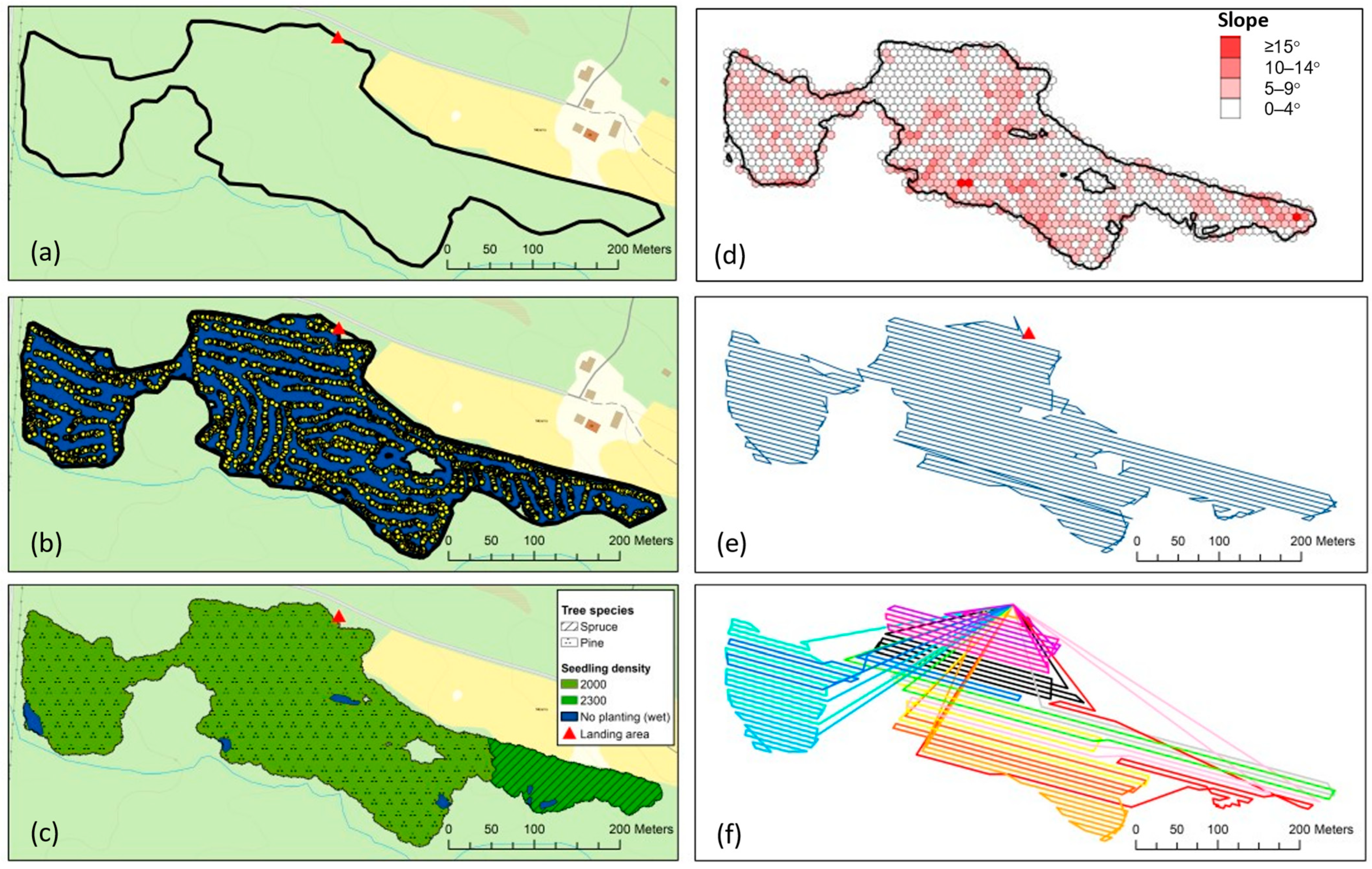
2.2.3. Pathfinder Results

The forest area planned for the Autoplant integration tests was 8.4 ha, and the net harvested area derived from the hpr files in PlantP was 8.1 ha, with an additional 0.1 ha excluded because of conditions that were too wet (Figure 2). The stand index (dominating tree height when the stand is 100 years) based on hpr data was 23, and PlantP suggested that 7.1 ha be planted with Scots pine at a density of 2000 seedlings ha−1 and 0.9 ha be planted with Norway spruce at 2300 seedlings ha−1 (Figure 2c). The total driving distance in Figure 2e is 15.0 km, of which 2.3 km is driving without planting. The suggested 14 routes, each including a maximum of 1500 seedlings, are presented in Figure 2f. The total number of seedlings is 16,200, and the total driving distance is 19.4 km, including 6.7 km without planting. The distance includes the machine following the border back to the landing, not taking the shortest route as visualized in the figure.

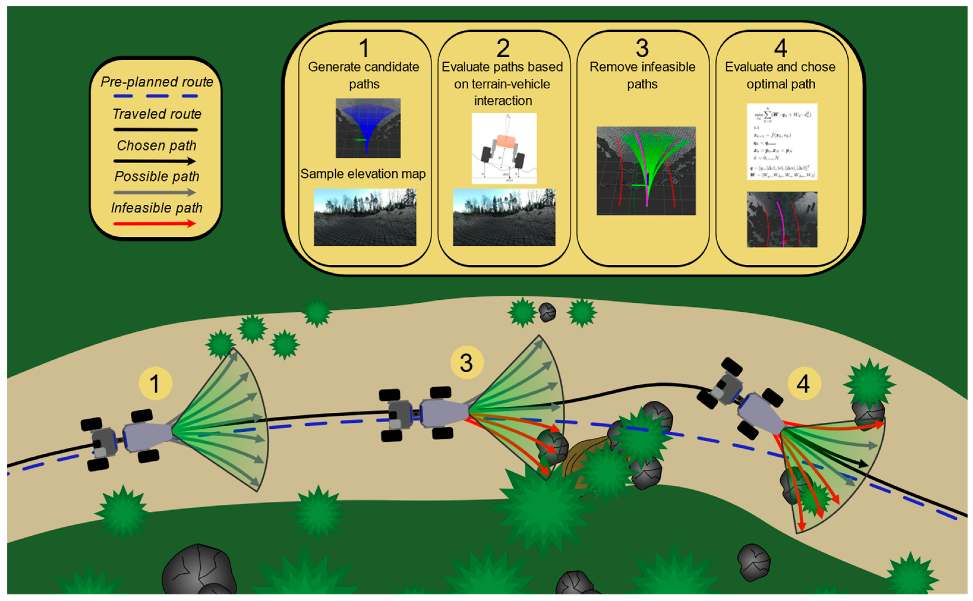
2.3. The Path Planner—Autonomous Navigation

It is not possible to precisely follow a global plan in harsh terrain, as the global plan never considers all variations in a clearcut area. Therefore, a local path planning system has been developed that is described in this section. Navigating autonomously in a harsh forest environment is challenging. Compared to on-road applications, the challenges center on machine–terrain interactions rather than vehicle–vehicle interactions and traffic rules. Even though tools for off-line route planning (global planning) are becoming more precise and advanced, local planning is still needed. The forest is not a static environment, meaning that divergence from a preplanned global route will and must be possible. The resolution from a global plan (here, the output from the Pathfinder decision support tool) could also be insufficient, resulting in a path suggestion impossible to traverse. Autonomously diverging from a global route and briefly following a local path is very similar to the case of a manually driven vehicle, where the operator needs to make local adjustments based on the terrain ahead. These local adjustments are based on the operators’ visual input of the terrain. To accomplish this while driving autonomously, an estimation of the terrain in front of the machine is essential.
In Autoplant, a full-scale test vehicle and a downscaled prototype [29] were both equipped with a stereo camera (ZED2, Stereolabs) in the front of the vehicle to sense the terrain. The sensor input was used to estimate a topology map of the terrain ahead of the vehicle. The topology map was generated using an elevation map developed in [30]. The vehicle is centered on the map and uses point cloud data, based on camera input, to estimate the topology of the terrain around and ahead of the vehicle. The elevation map can be seen as a function that maps height coordinates at the coordinate location, as shown in Equation (1), where M is a function that takes a coordinate pair, x , y , and gives the height h at that location: M x , y = h .
M : R 2 R : x , y h
For the local Path Planner to function, it needs to know its position relative to the global route. This positioning was performed using a combination of GNSS data and wheel odometry. The GNSS module gives the position and heading of the machine, providing there is satellite coverage, and wheel odometry compensates when coverage is lacking.
The developed local path-planning algorithm uses the preplanned global route from Pathfinder (Section 2.2) as a reference and uses a local trajectory rollout approach to generate candidate paths [31]. In the first step, candidate paths are generated in front of the machine, and the topology map is sampled. In the second step, the candidate paths are evaluated based on the vehicle–terrain interaction model, which evaluates a set of state parameters: ground clearance, slope, roll angle, roll angle velocity, and the change in steering angle compared to the previous path. In this step, the goal is to find all paths that are infeasible for the machine and remove them so that only the feasible paths remain, which is accomplished by comparing these parameters to their maximum allowed value based on the vehicle’s capabilities. The calculations of the state parameters are described in Equations (2)–(5).
Firstly, a path is defined as a set of consecutive points. Then, the vehicle model, which is only the front section of the machine, is evaluated at each of these points as shown in Figure 3a. This evaluation starts with the roll angle calculation in Equation (2), where the roll angle d w is calculated from the wheel span, z l , z r , and the height under the wheels at that position as defined in Figure 3b.
α = sin 1 z l z r d w
From the roll angle α , a discrete roll velocity can be calculated by looking at the difference in roll angle between two consecutive evaluation points. Let α k be the roll angle at the current evaluation point and α k 1 be the roll angle at the previous evaluation point; then, the roll velocity α ˙ can be calculated as α k ˙ = α k α k 1 . The slope is calculated for each wheel independently because it is meant to capture obstacles and terrain that the machine is unable to climb. The slopes Δ z l , k , Δ z r , k are defined as the difference in height between two consecutive evaluation points z l , k , z l , k 1 and z r , k , z r , k 1 as shown in Equation (3).
Δ z l , k = z l , k z l , k 1
The last state parameter evaluated along the paths is the ground clearance g c . This is the shortest distance between the bottom of the machine chassis and the terrain. To calculate this distance, the distance from the bottom of the chassis to the wheel–terrain contact must be known. Let that distance be d c , as shown in Figure 3b. Then, under the assumption that the roll angle α is small, the distance between the chassis and the ground at an arbitrary position p s is
Δ d c s = z s + d c M p s
Here, s 0,1 , p 0 are the coordinates of the inside of the left wheel, and p 1 are the coordinates of the inside of the right wheel. M p s obtains the height at p s from the elevation map, and z s is defined in Figure 3b. The resulting ground clearance is the minimum Δ d c between the wheels:
g c = min 0 s 1 Δ d c s
The final state parameter is the change in steering angle between plans. Because each candidate path has a constant steering angle, each plan will have the same. The steering angle of the path under evaluation can be compared to the steering angle of the previous selected path. This evaluation is included to handle cases where, as an example, an obstacle is straight in front of the machine and two candidate paths with similar optimality lie on each side of the obstacle. In this case, it would be preferable to choose one direction and continue, even if this would result in reduced optimality, to avoid a case where the machine zigzags toward the obstacle until it is too close to avoid. If the steering angle changed instantaneously, this would not be an issue, but changing direction takes some time in the real world. The change in steering angle Δ β can be calculated by Δ β = β c β p , where β c is the steering angle of the candidate path and β p is the steering angle of the last chosen path. Then, a cost vector q can be constructed by combining all of the state parameters: q = g c , Δ z , α , α ˙ , Δ β .
In the third step, all infeasible paths are removed as options by comparing each element of q against their maximum allowed value. In the fourth step, the remaining possible paths are evaluated as an optimization problem, which is done by weighting the parameters in q at each point in the paths and adding up the weighted parameters along the path. The resulting sum is viewed as the cost of the path under evaluation. In this step, the distance to the global route is also included as a factor, and the path with the lowest cost will be chosen and published as the new local plan, i.e., the selected path. The local Path Planner generates an updated path at 1 Hz. This allows the algorithm time to recalculate with new sensor data while ensuring continuous improvements of the overall path. The stereo camera covers 15 m ahead of the machine, and each plan is 6 m long, which allows the planner to react to obstacles in time due to vehicle speeds below 2 m/s. This does not limit the planner to including obstacles that can be handled by later samples. The local path-planning steps are illustrated in Figure 4.

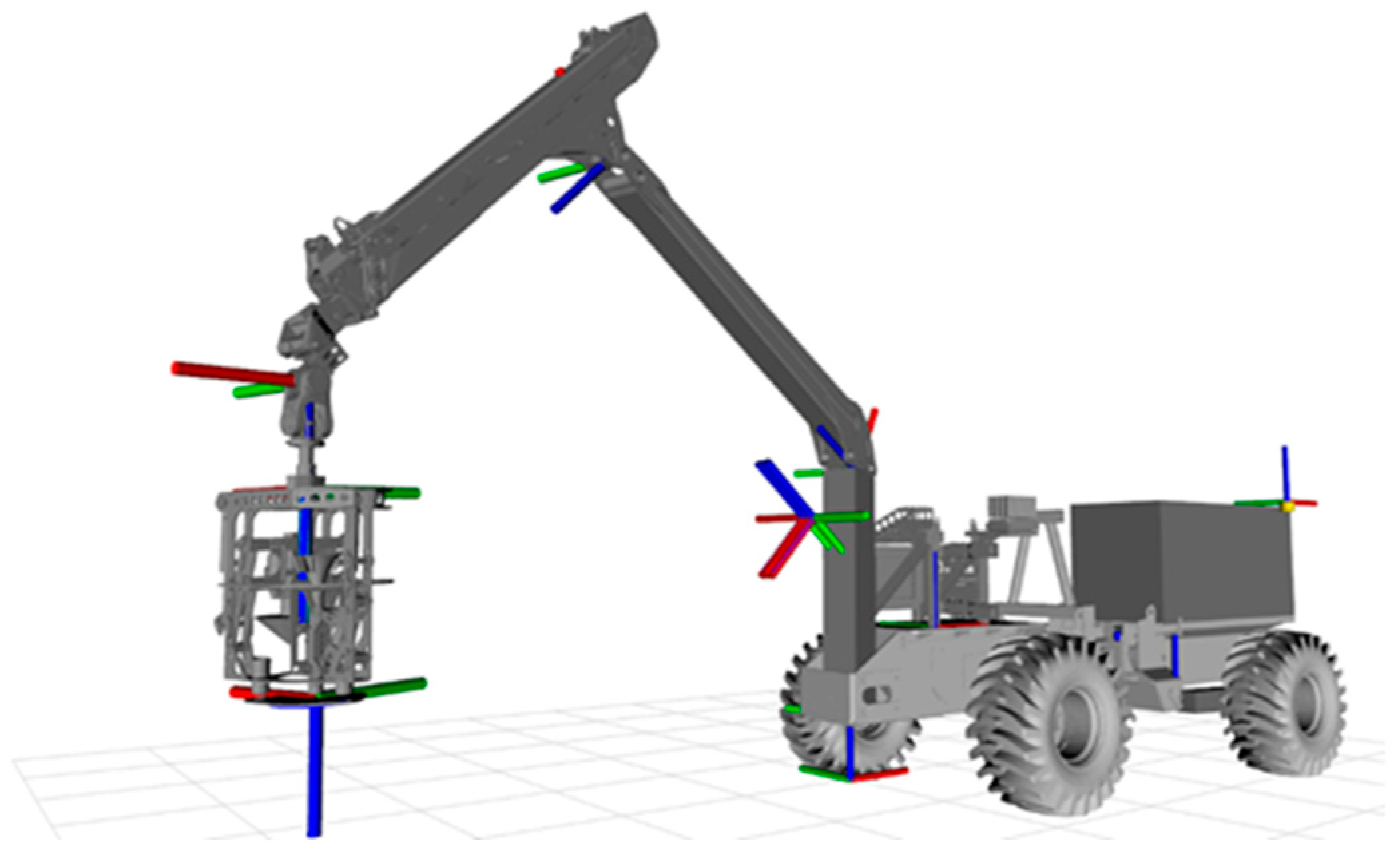
2.4. The Terrain Vehicle Platform

The primary tool for exploring forestry within Autoplant is a heavy-duty unmanned forest machine platform [32,33] (Figure 5), developed by The Machine Design Group at Luleå University of Technology, affiliated with the Arctic Off-Road Robotics Laboratory (AORO). The objective behind creating this unmanned forest machine is to test various robotic software solutions aimed at achieving fully automated forest operations. The machine has, for example, previously been used to successfully demonstrate autonomous forwarding [32].
The 10-ton platform comprises two chassis components: the front section houses the engine, hydraulic pumps, and most computing units, whereas the rear accommodates additional equipment, including a full-scale forest crane that can be interchanged with different modules, or other end-effectors added to the crane. These main sections are connected by a hydraulic articulation joint with 1 degree of freedom (DoF). Powering the machine is a diesel engine and a hydrostatic drivetrain with four hub motors. To allow for traversing over rough terrain, pendulum arms (1 DoF each) are individually controlled hydraulically. The engine also includes generators supplying 24 V and 12 V electrical power to the control units and sensors.
The control system consists of four primary computers with distinct functions. The first, a Ueidaq I/O computer named UEISIM, manages signals activating various mechanical components and gathers data from positional and pressure sensors. The second computer, an NVIDIA Jetson Xavier, is an embedded computing board focused on visual computing and object detection. This board interfaces with a stereo camera for environmental perception. The third computer is a laptop PC with Ubuntu 18.04 that acts as the ROS master in the system and executes most of the other ROS nodes. In addition, a PLC handles control for seedling transfer, site preparation, and planting. Through a local area network, communication is enabled among the three computers, and an analog bit logic interface comprises the communication interface between the PLC and the other computers.
There are positional sensors for all moving joints on the machine and the crane, except for the underactuated joint between the crane and the end-effector the Planter. Pressure sensors are installed on all hydraulic cylinders for precise monitoring. ZED2 stereo cameras from Stereolabs are fitted on both the front and rear of the machine. The platform is equipped with a Leica iCON GPS80 GNSS system featuring dual antennas for accurate localization. A remote emergency switch is in the hand of an operator at all times to ensure the machine can be stopped immediately at any sign of safety-related issues. The mission is otherwise started and stopped from a remote laptop connected to the same local area network.

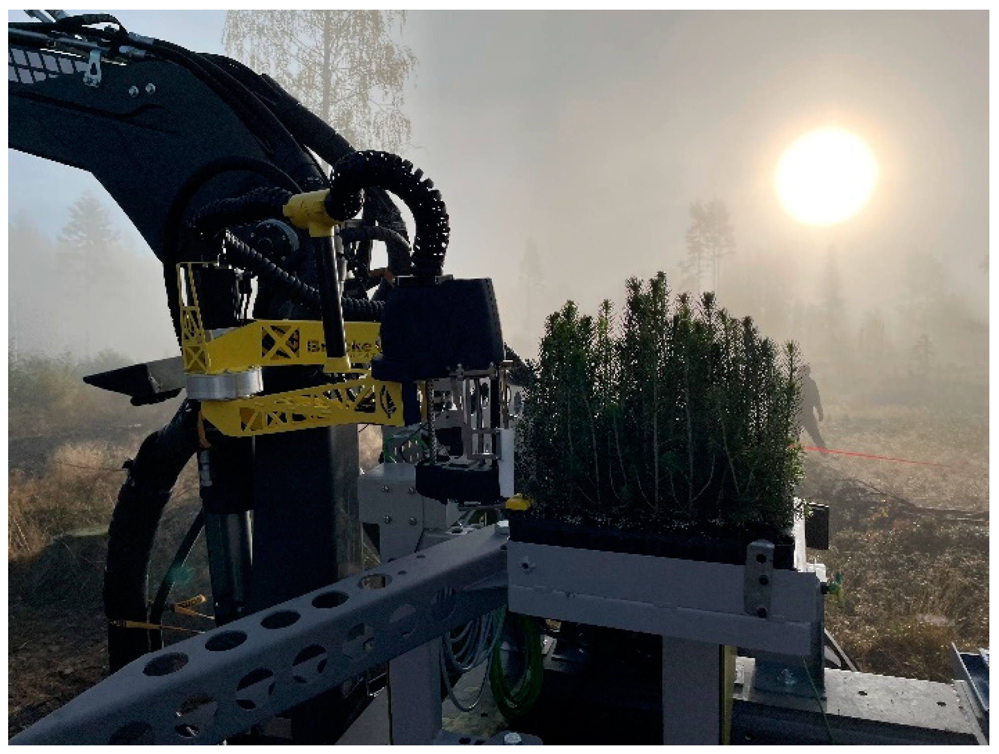
2.5. The Planter—New Technology for Forest Regeneration with Low Environmental Impact

A major challenge in developing new technology for forest regeneration with low environmental impact was to make the Planter (the site preparation and planting device) lightweight and compact but with sufficient strength and power to perform a sufficient site preparation. Bracke Forest AB, as detailed on its official website (www.brackeforest.com), holds a prominent global position in the development and manufacturing of silvicultural technology. This company has garnered recognition for its robust, heavy-duty site preparation equipment, which is designed for integration with forwarders. It is also noted for its advanced planting heads, specifically engineered for attachment to excavators. To develop a new planting device specific to the Autoplant system, about 45 rough concepts were generated and evaluated during several brainstorming sessions, of which some were 3D-modeled to check their feasibility. One conclusion from those sessions was that site preparation was the most challenging part to solve.
To gain a further understanding of a few main principles, three site preparation ideas were chosen and manufactured for testing (Figure 6). The three concepts were (1) a digging concept with a rake-shaped blade that rotates around a horizontal axis, (2) a drilling concept with a spiral, and (3) a scraping concept that scrapes the soil apart with two blades moving parallel to the ground. The designs went through several iterations to test and evaluate their weight, hydraulic demand, and anchoring ability and the quality of the site preparation spot. For example, different kinds of methods were used to obtain a stable anchoring point against the ground. Many tests were conducted both indoors and in the field before a decision was made on which one to use in the final concept. The pros and cons of the three site preparation devices are summarized in Table 2. The drilling concept made the best planting spots consistently and was chosen to be integrated into the final concept (Table 2).
The planting part in the final concept made use of a modified planting tube, which can be compared to a standard manual planting tube, mounted on a parallel linked arm. The drill was also mounted on a parallel linked arm on the opposite side of the planting tube. This was done to achieve a simple and compact device that would scarify and plant in the exact same spot.
The final tests of this concept are promising, and they show a proof of concept that lightweight (around 200 kg) and compact devices like this can achieve an approved result that combines the scarifying and planting parts in 11 s.

Camera for Following Up Planting

The planting follow-up camera was based on an FLIR Blackfly, mounted within a surveillance camera chassis for weather protection. The assembly had a magnet mounting plate and adjustable joint to allow for view adjustment. The magnet attached the camera assembly to the Planter. The camera had its own computer hardware, an NVIDIA Jetson Nano, in a separate enclosure housing. An ROS node was running on the Nano that connected to the machine network using Wi-Fi (Figure 1). In the proposed concept, camera images are taken of both planted seedlings and failed planting attempts. The images can be stored together with metadata such as machine and planting position and machine parameters. Although not further explored in the project, this enables the development of systems for automatically grading the quality of the planting.

2.6. Automatic Seedling Transfer

Early in the workshops held with all participating companies in the Autoplant project, a decision was made that the seedlings should be picked directly from the Hiko-trays (BCC AB, Landskrona, Sweden) in which they are delivered from the nursery. An onboard storage of 1500 seedlings was seen as reasonable to fit on the available terrain vehicle platform, but a single Hiko-tray was used for the integration tests (Figure 7). Automatic seedling transfer from the storage to the planting device is important for increasing the productivity of mechanized planting [34,35] but is challenging due to the sensitivity of the seedlings.
In parallel with the development of the scarifying and planting device, a picking robot was developed by Bracke Forest to transfer seedlings from the onboard storage to the planting device. The picking tool and robot itself were developed in an earlier project [36]. The robot is an SCARA type of robot with the tool mounted on the arm (Figure 7). The tool uses the z-axis (i.e., up-and-down motion) to lift the seedling from the tray. It then rotates around and drops the seedling into the planting tube of the Planter.

2.7. The Crane Controller—Motion Planning of the Crane

The crane client subsystem used MoveIt™, a key component of the ROS package suite renowned for its extensive robotic motion planning tools [37]. This software leverages the joint_trajectory_controller from ros_control, enabling precise control over robotic arm movements [38]. It seamlessly integrates essential robotics elements, including kinematics, dynamics, and sophisticated control techniques. A significant feature of MoveIt is its collision avoidance algorithms, essential for the safe and efficient operation of robot arms.
The joint_trajectory_controller processes trajectories from MoveIt to guide the robot arm movements, employing precise control over each joint. The controller utilizes PID joint controllers, which are integral parts of the ROS control system. For these controllers to effectively manage machine movements, an ros_control hardware interface is required, typically implemented in C++. The full control path is illustrated in Figure 1. Hydraulic cranes are typically nonlinear systems with considerable intrinsic dynamics. Nevertheless, modern hydraulic systems generally include a load-sensing feature, which minimizes the interaction among different actuators. The output from a control valve is closely related to the corresponding actuator speed. By conducting calibration measurements to assess the joint speed at varying valve control signals, a linearization table was developed. This table correlates the desired joint speed with the corresponding valve control signal. With this linearized control being employed as a velocity joint interface in ros_control, the crane could be handled like a robotic arm within the MoveIt and ROS framework.
Although our crane control system has not yet matched the proficiency of an experienced human operator, it demonstrated satisfactory performance as a proof of concept within the limited timeframe of the project. However, the complexity inherent in ros_control, particularly in developing the C++ hardware interface necessary for MoveIt activation, posed significant challenges. This complexity was partly attributed to the nature of ros_control hardware interfaces, which function more like plugins than traditional ROS nodes in terms of communication.

2.8. The Planting Planner—Detection of Planting Spots

Effective planting requires the strategic placement of seedlings. A proficient plant planning system is therefore essential to discern viable planting locations while avoiding unsuitable ones. In the Autoplant project, this challenge is addressed using an obstacle detection system. This can visually identify obstacles like stumps and stones and determine their size and location within the machine’s operational area. The core of the obstacle detection relies on data from a ZED2 stereo camera, complemented by a bounding box detection from the YOLO family. The initial development and training of this AI system are described in [39], and transfer learning was used to merge the work to a contemporary YOLO detector (version 7). The obstacle detector used in the project exhibits a mean average precision (mAP) of 0.80 at an IoU threshold of 0.5. Mean average precision is the typical way of evaluating a detector’s performance across its classes [40].
The plant planning algorithm focuses on selecting locations that maintain a safe distance from detected obstacles and existing seedlings. To achieve this, the Planting Planner initially projects all detected obstacles onto a 2D map of the work area. It then performs a convolution of this map using a specially designed kernel. This kernel embodies the necessary margins required around each seedling, ensuring adequate space for growth. The algorithm processes the convoluted map to pinpoint positions where the values fall below a predefined threshold, indicating suitable planting locations. After each planting attempt, the 2D map is updated, and a new convolution is performed. The projected map and how detected obstacles are projected are illustrated in Figure 8 and described thoroughly in [41].
The developed method is computationally efficient and highly adjustable. Various parameters can be fine-tuned, such as the design of the convolution kernel and the values assigned to projected obstacles on the map, allowing the system to be tailored to different environmental conditions and planting requirements.

3. Integration Tests and Experiments

3.1. Integration Tests at a Forest Regeneration Area

The Autoplant system was integrated and tested together during a week in September 2022 at a regeneration area (clearcut) in the vicinity of Bräcke, Sweden, 62.9130° N, 15.6330° E (WGS84). The hardware developed by Bracke was mounted on the terrain vehicle platform, and the mechanical, hydraulic, and electrical interfaces were connected. The assembly itself went well, as all participants had made use of their respective digital twins.
In the field test, full autonomous site preparation and planting were demonstrated, 1.5 years after the project started (Figure 9). However, in the first test, only a limited number of planting cycles were completed successfully during the two days when the machine was in operation at the clearcut. The main reasons for interruptions in the autonomous execution were the improper configuration of the crane ground clearance model and the overheating of one of the main computers. Once the overheating issue was identified, it was easily solved by increasing the cooling of the computers. To enable proper crane operation, the crane tolerance settings had to be adjusted, and the ground clearance model was redesigned. However, these modifications came at the expense of valuable experimental time.
The tests followed the operation path description in Section 2.1, but only one staging area was tested each time, and the autonomous navigation was therefore not evaluated to the fullest. The tests showed that the integration was successful, with all interfaces working.
During system development, considerable attention was devoted to ensuring safe operation, particularly concerning the crane’s behavior. Consequently, the system exhibited a conservative tendency, favoring aborts over taking risks. One significant advantage of employing a state-machine-based control system lies in its capacity to take appropriate actions to recover from error events. Regrettably, during the integration testing phase, the system had not reached the desired level of completeness in this regard. Future designs should incorporate an error recovery strategy encompassing all states. Transitioning the system to ROS 2 would enhance system monitoring and reliability [42]. Additionally, it is advisable to include monitoring of machine parts and computing hardware parameters, such as temperature and processor load. It can also be noted that streamlining the start process should have been prioritized, as rebooting multiple scripts on multiple computers is a time-consuming endeavor.

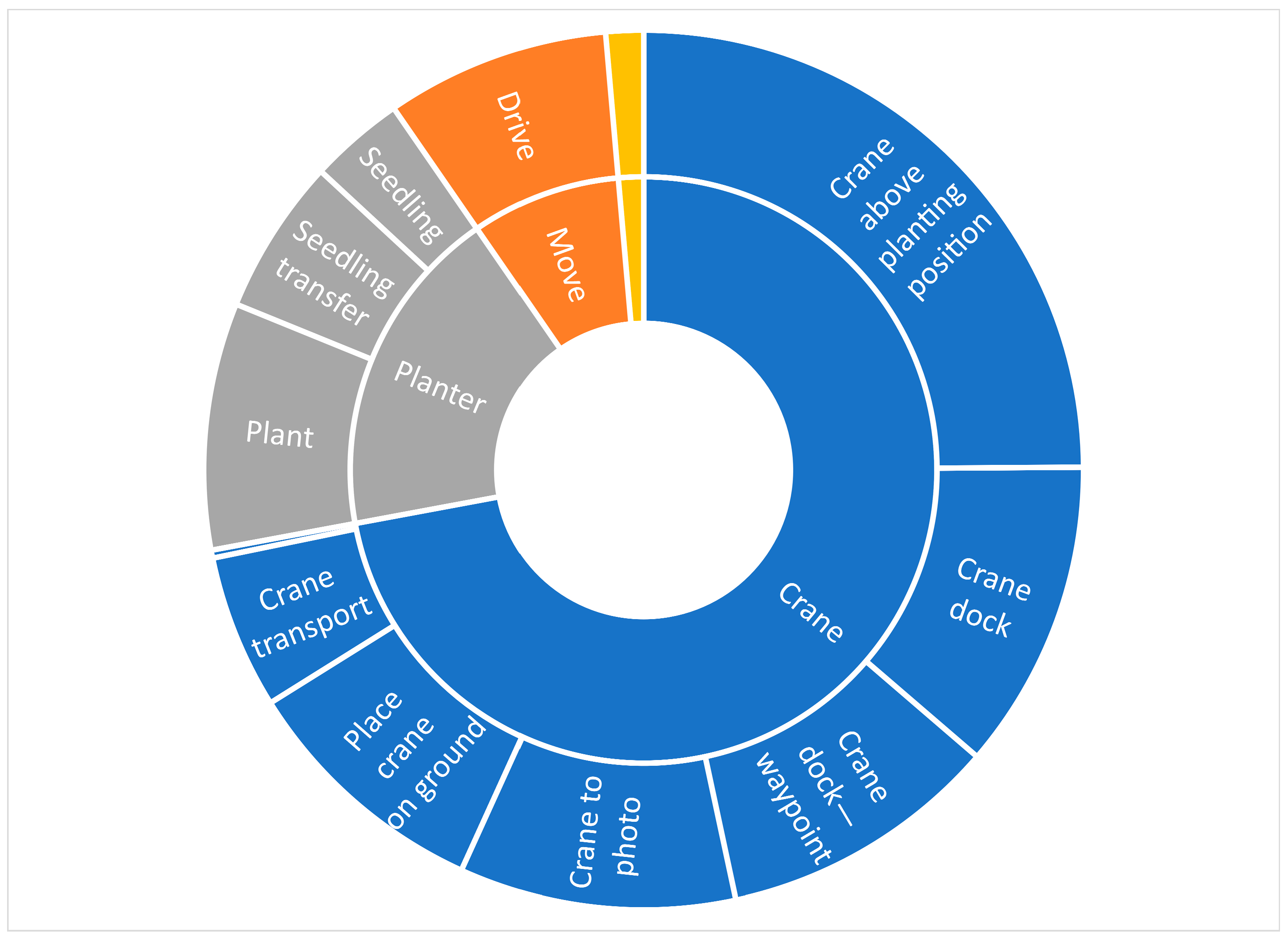
3.2. Field Experiment

In addition to the field tests outside Bräcke, a field experiment was conducted focusing on the evaluation of the overall control of the machine. During these experiments, the concept was able to perform its operation continuously without issues. Additionally, a few simplifications were made to the setup. The actual planting unit was not added as hardware. Instead, an emulator was added to the system that used the same amount of time (11 s, see Section 2.5) to perform the same actions as the real hardware. The location was also easier, a flat grass area scattered with artificial birch stumps at Skogforsk Sävar research station, 63.8944° N, 20.5489° E (WGS84), located close to the town of Umeå in Sweden. Dummy obstacles were scattered on the ground with known positions, and the obstacle detector and Planting Planner operated as intended. This setup made it possible to record the operation times of the system parts (even if some were emulated). The results are presented in Figure 10.
The experiment served as a simulation model validation. The simulation model was a real-time simulation model developed in ROS as a Python node, which mimicked the velocities of joints in the machine. The real-time simulation differs from the discrete-event simulation described in Section 4. The real-time model demonstrated an agreement in timing within 10% for most crane operations. Two primary reasons account for the observed differences. First, the simulation featured obstacles similar in type and size but at uniformly random locations, resulting in varied crane movements. Second, for identical movements like crane docking, the actual machine operated more slowly than the simulator. This discrepancy is likely caused by the machine’s slower response at the start of a movement. Such dynamics are not fully addressed by the linearization table in the controller (Section 2.7), leading to differences in movement speed between the simulation and the actual machine. Although a 10% variance may be acceptable in this application, modeling this nonlinear behavior in the hydraulics might enable further movement improvements. Machine movement was highly underestimated in the simulation because acceleration was ignored by the model, and a 30% deviation was seen.

4. System Analysis

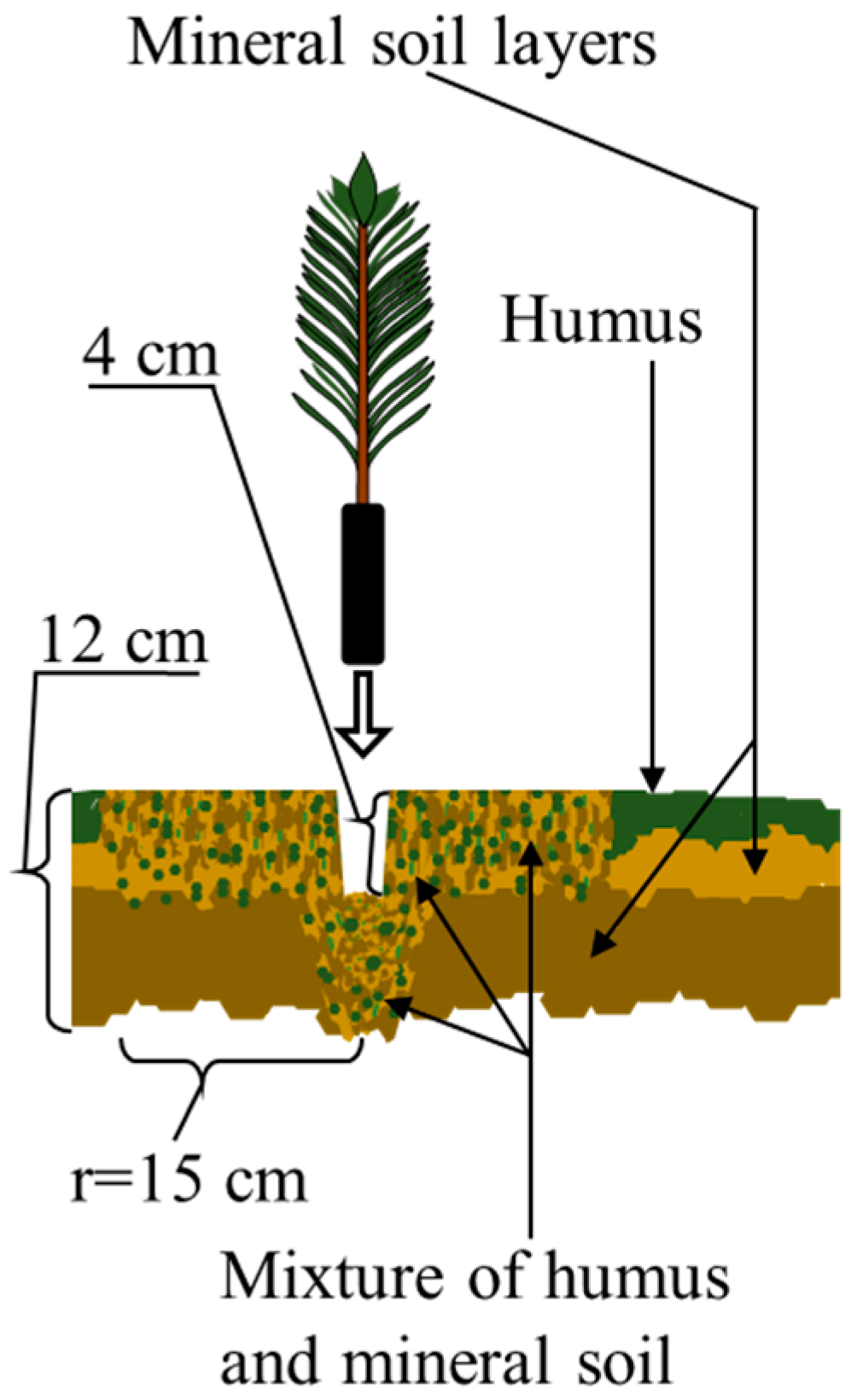
4.1. Modeling the Machine–Soil Interaction

The potential of autonomous planting machines in a conceptual context was assessed by system analysis using discrete-event simulation.
The soil, specifically obstacles, was modeled based on previous research and real-life datasets [43,44,45,46,47,48]. These obstacles encompassed stones and boulders, roots, and stumps. Stones and boulders were represented by six different sizes: 125 cm3, 3375 cm3, 27,000 cm3, 91,125 cm3, 216,000 cm3, and 421,875 cm3. The overall soil stoniness was set at either 20% or 40%. Fourteen percent of the regeneration area was assumed to be covered by stumps and roots (including the zone of rapid taper).
We assumed that the Planting Planner (see Section 2.8) could detect stumps and boulders above the surface and therefore avoid them during site preparation and planting. In contrast, roots and stones below the ground surface were nondetectable. Hitting a nondetectable object would result in the failure of site preparation (and subsequently planting). The minimum allowable distance between planted seedlings was set at 2.0, 2.2, or 2.4 m.
The Planter, i.e., the drilling concept developed by Bracke Forest AB, creates planting spots with a depth of 4 cm, a borehole depth of 12 cm, and a spot diameter of 30 cm (Figure 11). As the planting tube uses the same borehole for planting, there is no risk of encountering obstacles during planting, only during soil preparation. We assumed that the smallest stones (size 125 cm3) do not impede site preparation, whereas larger stones or boulders could obstruct both site preparation and planting. Because the smallest stones accounted for 40% of the stone mass, the effective soil stoniness during the simulation was either 12% (i.e., 0.6 × 0.2) or 24% (i.e., 0.6 × 0.4).

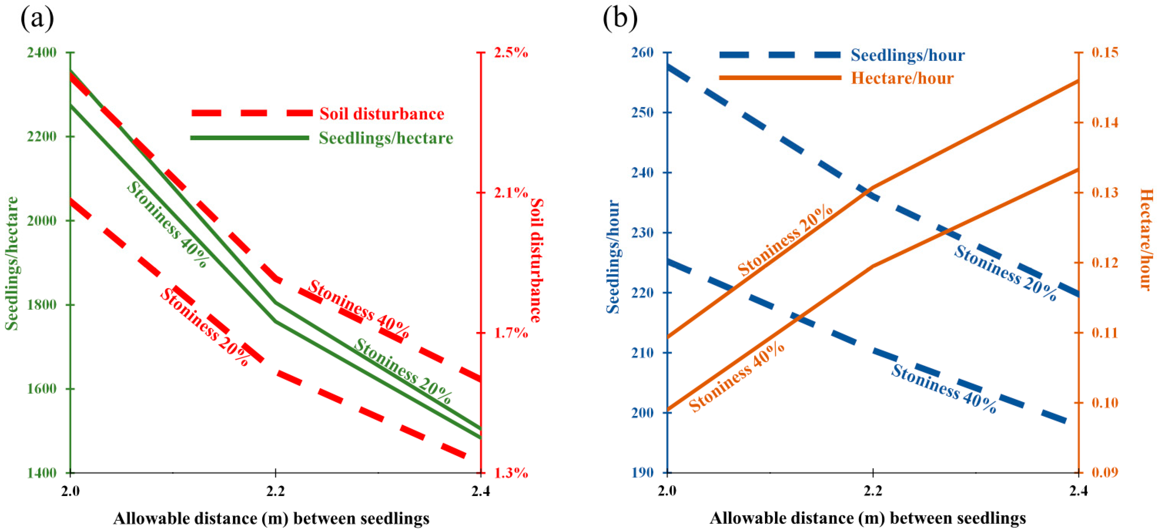
4.2. Simulation Results

The number of planted seedlings ranged from 1500 to 2300 per hectare, depending on the minimum allowable distance between seedlings (Figure 12a). The planting densities aligned with the preferences of the Autoplant collaborative project group. Stoniness had minimal impact on planting density, but it did slightly increase soil disturbance. That said, in all cases, the soil disturbance was below 3% of the area. Machine settings can be adjusted to closely approximate the desired density, but the exact number of seedlings that will survive varies. Generally, the optimal planting density in economic terms is influenced by various factors, including site fertility and interest rates. For instance, the Swedish Forest Agency suggests that the net present value of a stand is optimized when 1000–1500 seedlings are planted per hectare, depending on site fertility [49]. Furthermore, in Fennoscandia, any gaps between planted seedlings are typically filled with naturally regenerated trees, fostering the development of mixed forests, which is beneficial in a number of ways [50].
Productivity was primarily affected by the minimum allowable distance between planted seedlings (Figure 12b). A denser planting resulted in more seedlings planted per hour due to a decreased proportion of time spent driving. However, when analyzed per hectare, the situation was the opposite. A sparser planting arrangement allowed the machine to cover a larger area per hour. The increase in productivity eventually began to decline as the relative proportion of driving time (a constant addition) became more significant.

5. How the Autoplant Concept Helps Solve Societal Challenges

In the emerging bioeconomy, a balance is needed between increased production and regeneration so that the forest maintains its function as a carbon sink while also meeting the new production needs. Our solution is fast forest regeneration with precision site preparation and planting to avoid unnecessary soil disturbance and give the planted seedlings a head start by ensuring sufficient planting spots (the Climate Challenge).
The Autoplant concept has the potential to reduce soil disturbance from today’s 17–70% [8] to less than 3% of the regeneration area (Figure 12a, the Environmental Challenge). In addition, decision support tools such as Pathfinder avoid soil disturbances in sensitive soils (too wet or too dry) and exclude NoGo areas such as historical remains, and they provide the operator with a plan for operation where those areas are already excluded (Section 2.2). However, detecting unmarked historical or cultural remains might become more difficult when the operator is no longer on board the machine. On the other hand, many of the remains (for example charcoal pits) are more easily detectable on a DEM derived from high-resolution LiDAR scans than by the human eye at the site.
In the two-year Autoplant project, there was not enough time to evaluate the planting success in terms of the survival and growth of the planted seedlings compared to manually planted seedlings. However, previous studies have indicated that mechanical planting has been of high quality compared to average manual planting [51,52]. The presented planter unit does not work in exactly the same way as the devices studied previously, and the actual seedling survival rate is a critical aspect of future evaluation. The project has recently received funding for two more years of development and evaluation of the entire Autoplant system, and seedling establishment experiments in different site conditions are an important part of this work.
Manual planting also puts a lot of strain on the planting team, as they need to carry the planting equipment and press it into the potentially stony soil, as well as carry all the seedlings on foot through rough terrain (the Work Environment Challenge). By mechanizing the planting process, the work is transformed from harsh physical labor to operating machines. Mechanical site preparations by scarifiers are today associated with a lot of whole-body vibration, and moving the operator from the machine to the ground automatically reduces these vibrations to zero. Planting machines with a higher level of autonomy open new ways of working, where one operator could manage several machines at the same time. In this scenario, the operator would be responsible for starting the machines and then overseeing their work. If this concept is taken one step further, the operator might not be needed on-site and could instead manage the machines from an office setting. The new tasks could attract other people than those currently employed for the physical hard regeneration work [53] (the Workforce Challenge).
A key feature of the Autoplant concept is precision, and the concept provides a good start for precision forestry [54]. If the goal of improved seedling establishment is reached, fewer seedlings will need to be planted per hectare, and costs can be reduced. The coordinates and information about the planted seedling, such as tree species and type, are stored and may serve as a starting point for a digital twin of the forest [55]. The digital twin can be used for modeling how different forms of forest management, such as precommercial thinning and thinning, affect the stand and its economic or biological value. When the exact coordinates of genetically improved planted seedlings are known, it is easier to make sure that these trees are not removed during precommercial thinning. Known seedling coordinates also allow for precision low-dose fertilization.

6. Opportunities Afforded by the Autoplant Subsystems

The different subsystems have a wider potential for use than the Autoplant concept. The decision support tool Pathfinder (Section 2.2 [27]) could be used for any planting machine. The continuous route (Figure 2e) could also be used for traditional scarifiers, to improve the estimation of the area in which they operate, minimize time-consuming U-turns, and shorten the overall driving distances, thereby reducing time and fuel consumption.
The local Path Planner (Section 2.3) could be used as an operator support tool that suggests paths to an operator driving a machine. The planner is not machine-specific, except for the “maximum parameters” that allow it to be used on any articulated vehicle. Outside real-world implementation, it could be used in simulations to increase the resolution, and it could plan routes by driving the planned routes in a simulation to further improve them.
The vehicle platform (Section 2.4 [32]) can be used for testing various robotic software solutions aimed at achieving fully automated forest operations. The Planter (Section 2.5) is a new lightweight site preparation and planting device, although it is still in the early prototype stage. It demonstrates that site preparation and planting can be performed with a device with a weight that is only 10–15% of that of the Bracke products currently on the market (www.brackeforest.com). This enables new applications for smaller machines (with or without onboard operators), especially if continuous cover forestry increases, and the need for light site preparation and planting in cap cutting or in shelterwoods increases in areas where natural regeneration is insufficient [22]. The robot arm for automatic seedling transfer (Section 2.6 [36]) developed by Bracke can be used not only for loading seedlings to the Planter but also for transferring seedlings from trays to other seedling storage units on the machine or to carousel trays connected to the planting device. This has been pointed out as a crucial step to solve, generally, in mechanized planting [16].
Because the motion planning of the crane (Section 2.7) did not reach the performance of a human operator, the method of linearizing the control allows for further development, since the crane now can be handled as a normal robotic arm. This makes it possible to use standard and readily available software for crane control.
The planting spot detector (Section 2.8 [41]) could be used as an operator support tool to indicate where there are suitable planting spots for mechanized planting. Its lightweight setup, with stereo imagery as the main input, allows it to be used to preplan where to plant seedlings, by scanning the area with stereovision beforehand.
The tool for system analysis of the planting machine–soil interaction (Section 4 [48]) could be adapted for other applications to test, for example, the soil disturbance level and productivity of other forest regeneration machines, given different soil conditions and the density and size of tree stumps.

7. Challenges Still Facing the Autoplant Concept

The specific objective of the two-year Autoplant project was to develop and test the different subproducts needed to make the future system work, integrate the subsystems, and demonstrate autonomous site preparation and planting. A fully autonomous site preparation and planting cycle was demonstrated in full scale and real time in a forest regeneration area (real environment) in September 2022 (Section 3). However, this was a proof of concept and an integration test for testing the subsystems together. The concept is far from a commercial product, and several improvements are needed before a final prototype may be presented:
  • Robustness needs to increase in all sensors and subsystems, as reducing machine down-time has been identified as an important factor for planting machine productivity [16]. The forest environment is rough, and mechanical site preparation produces dust that can affect cameras and sensors. Vibrations when traversing the terrain, as well as every time the Planter hits stones and boulders, also put great strain on the equipment. Different weather conditions and different sun angles also increase the amount of training data needed to create a system that can operate in all conditions. Precision in detecting objects and their size and placement around the machine also needs to increase. For example, fusing sensor data from several sources with filtering techniques can counteract drawbacks caused by poor data from individual sensors [56].
  • Instead of a crane, the machine needs one or several fast arms to carry the Planter(s) and plant enough seedlings every hour. Autonomous machines may not have the same productivity demands as manually operated machines or tools, but operators are needed to start up the machines, monitor them, and reload them with seedlings. The machine productivity must compensate for the costs of its capital and energy use. Reaching a high level of productivity is a key factor for success [16]. From the time study (Section 3.2), it is evident that the concept needs a fast actuator (crane or robotic arm) to move the Planter into position quickly. It would also be beneficial if the Planter could carry at least the quantity of seedlings needed to plant a staging area and collect more seedlings while the machine moves to the next staging area. If the investment cost can be kept down and the size allows for easy transportation between regeneration areas, it would be possible for an operator to handle three machines at the same time with the Autoplant concept [48].
  • A suitable commercial base machine is needed for the concept. The vehicle platform developed by LTU and used in this project was developed to serve as a base for off-road automation research and is not designed to be a commercial product. The size may be appropriate for the task, but more research is needed to evaluate its accessibility in rough terrain. The base machine in the Autoplant concept needs to fulfill the hydraulic demand of the Planter, store at least 1500 seedlings, and be able to traverse rough terrain with boulders and stumps. There are large machines, for example, forwarders, which manage these tasks today, but few lighter and cheaper base machines with good terrain capability are available on the market. Future research includes finding the optimal setup for this kind of lighter terrain vehicle.
  • To enable autonomous forestry systems in Sweden, legislation must change. Today, an operating area needs to be fenced off with, at minimum, continuous hazard warning tape. The cost of putting up the tape on fence posts is enough to ruin the economy of the entire regeneration operation. New regulations and safety systems are needed where, for example, geofencing [57] can replace physical fencing. The safety systems developed in other projects need to reach a level where they can detect humans and larger mammals within the safety zone of the machine.
  • Previous research has identified seedling packaging, transport, and transfer as a bottleneck in the breakthrough of mechanical planting [16,34,35,58]. If seedling trays were optimized for mechanical planting and the handling systems were more cost-efficient, the potential for mechanized planting would increase [16,59,60]. However, the automatic seedling transfer in the Autoplant concept allows for efficient seedling transfer with the present Hiko-tray system.
These improvements will be addressed in the new two-year phase of the project, funded by the Swedish Innovation Agency, Vinnova. This phase will involve large-scale testing of different subproducts, including experiments on seedling establishment where the Autoplant system will be compared to traditional methods. More focus will be directed toward the work environment and human–machine interactions. Bracke Forest will develop a plan for commercialization, and lobbying efforts will be carried out to bring about the changes in Swedish legislation needed before autonomous vehicles can be used in forestry.
It may take a while until autonomous planting machines for rough boreal forest terrain reach the market, but to reach the final goal, we must start somewhere, and the Autoplant concept has tested some directions of the necessary system development. Some of the subproducts might reach the market before the final concept is mature.

8. Conclusions

The Autoplant project has demonstrated fully autonomous site preparation and planting cycles at full scale and in real time in a real-world environment. However, the integration test was very short, and the project focus was on developing and testing the different subsystems needed for the future system to work. Varying amounts of development and testing remain until the subsystems can be used within operational forestry. Precision site preparation and planting help give the planted seedlings a head start and are our solution for addressing the Climate Challenge by both sequestering carbon in biomass and using more wood products to decrease greenhouse gas emissions. The Autoplant concept, with high precision, allows for a system shift toward a more sustainable bioeconomy. The concept has the potential to drastically reduce soil disturbances during forest regeneration. The lightweight precision Planter also has the potential to decrease the size of the base machine, resulting in less machine-induced soil disturbances such as soil compaction and rutting. The Autoplant project highlights the challenges and opportunities regarding future development, e.g., the relation between machine cost and operating speed, sensor robustness in response to vibrations and weather, and precision in detecting the size and type of obstacles during autonomous driving and planting.

Author Contributions

Conceptualization and methodology: L.J.H., G.S., M.R. (Morgan Rossander), H.L., R.v.W., S.L., J.M., A.E., A.W., P.F., M.R. (Mikael Rönnqvist), B.E., B.M. and M.K.; software: G.S., M.R. (Morgan Rossander), H.L., R.v.W., S.L., J.M., A.E. and P.F.; validation, formal analysis, and investigation: L.J.H., G.S., M.R. (Morgan Rossander), H.L., R.v.W., S.L., J.M. and A.E.; resources, all participating organizations; data curation: L.J.H., G.S., M.R. (Morgan Rossander), H.L., R.v.W. and S.L.; writing—original draft preparation: L.J.H., G.S., M.R. (Morgan Rossander), H.L., R.v.W. and J.M.; writing—review and editing: A.E., A.W., M.R. (Mikael Rönnqvist), B.E., B.M. and M.K.; visualization: L.J.H., G.S., M.R. (Morgan Rossander), H.L., R.v.W. and J.M.; supervision: H.L., B.M. and M.K.; project administration: L.J.H.; funding acquisition: L.J.H. (in cooperation with the entire project group). All authors have read and agreed to the published version of the manuscript.

Funding

This research and development project was funded by the Swedish Innovation Agency, VINNOVA, grant number 2020-04202, and participating organizations in the collaboration project “Autonomous forest regeneration for a sustainable bioeconomy (AutoPlant)”, i.e., Bracke Forest AB, SCA AB, Södra Skogsägarna ekonomisk förening, Holmen Skog AB, Sveaskog, Skogforsk—the Forestry Research Institute of Sweden, Luleå University of Technology, The Royal Institute of Technology—KTH, and Skogstekniska Klustret (the Swedish Cluster of Forest Technology).

Data Availability Statement

See the publications on the different subsystems [24,27,33] for data availability. This paper summarizes the complete project and ties the parts together. The data presented in this paper may be available upon request.

Acknowledgments

We would like to thank the following people for valuable input and contribution to this project: the entire team at Bracke Forest led by Klas-Håkan Ljungberg; Magnus Bergman (SCA) and his colleagues who initiated the Autoplant project; Magnus Petersson (Södra); Olov Norgren and Sara Nilsson (Holmen); Jörgen Westman and Anders Järlesjö (Sveaskog); Linda Nyström (Skogstekniska klustret); Fredrik Johansson, Petrus Jönsson, Tobias Semberg, Anders Nilsson, and Gert Andersson (Skogforsk and the Troëdsson Teleoperation laboratory); Torbjörn Lindbäck (LTU); Lars Svensson (KTH). We also want to thank Leslie Walke for language edits.

Conflicts of Interest

The participating organizations in this collaboration project are also funders. They have had an active role in designing the subsystems, but have not influenced the scientific experiments or the interpretation of the results.

References

  1. Schulze, E.-D.; Wirth, C.; Heimann, M. Managing forests after Kyoto. Science 2000, 289, 2058–2059. [Google Scholar] [CrossRef]
  2. Janssens, I.A.; Freibauer, A.; Ciais, P.; Smith, P.; Nabuurs, G.-J.; Folberth, G.; Schlamadinger, B.; Hutjes, R.W.A.; Ceulemans, R.; Schulze, E.D.; et al. Europe’s Terrestrial Biosphere Absorbs 7 to 12% of European Anthropogenic CO2 Emissions. Science 2003, 300, 1538–1542. [Google Scholar] [CrossRef]
  3. Jandl, R.; Lindner, M.; Vesterdal, L.; Bauwens, B.; Baritz, R.; Hagedorn, F.; Johnson, D.W.; Minkkinen, K.; Byrne, K.A. How strongly can forest management influence soil carbon sequestration? Geoderma 2007, 137, 253–268. [Google Scholar] [CrossRef]
  4. Gustavsson, L.; Haus, S.; Lundblad, M.; Lundström, A.; Ortiz, C.A.; Sathre, R.; Truong, N.L.; Wikberg, P.-E. Climate change effects of forestry and substitution of carbon-intensive materials and fossil fuels. Renew. Sustain. Energy Rev. 2017, 67, 612–624. [Google Scholar] [CrossRef]
  5. Ali, N.; Jaffar, A.; Anwer, M.; Khan, S.; Anjum, M.; Hussain, A.; Raja, M.; Ming, X. The greenhouse gas emissions produced by cement production and its impact on environment: A review of global cement processing. Int. J. Res. 2015, 2, 488–500. [Google Scholar]
  6. Mjöfors, K.; Strömgren, M.; Nohrstedt, H.Ö.; Johansson, M.B.; Gärdenäs, A.I. Indications that site preparation increases forest ecosystem carbon stocks in the long term. Scand. J. For. Res. 2017, 32, 717–725. [Google Scholar] [CrossRef]
  7. Mäkipää, R.; Abramoff, R.; Adamczyk, B.; Baldy, V.; Biryol, C.; Bosela, M.; Casals, P.; Curiel Yuste, J.; Dondini, M.; Filipek, S.; et al. How does management affect soil C sequestration and greenhouse gas fluxes in boreal and temperate forests?—A review. For. Ecol. Manag. 2023, 529, 120637. [Google Scholar] [CrossRef]
  8. Sikström, U.; Hjelm, K.; Holt Hanssen, K.; Saksa, T.; Wallertz, K. Influence of mechanical site preparation on regeneration success of planted conifers in clearcuts in Fennoscandia—A review. Silva Fenn. 2020, 54, 10172. [Google Scholar] [CrossRef]
  9. Sutton, R.F. Mounding site preparation: A review of European and North American experience. New For. 1993, 7, 151–192. [Google Scholar] [CrossRef]
  10. Örlander, G.; Gemmel, P.; Hunt, J. Site preparation: A Swedish overview. In FRDA Report; BC Ministry of Forests: Squamish, BC, Canada, 1990; pp. 1–61. [Google Scholar]
  11. Ersson, B.T.; Cormier, D.; St-Amour, M.; Guay, J. The impact of disc settings and slash characteristics on the Bracke three-row disc trencher’s performance. Int. J. For. Eng. 2017, 28, 1–9. [Google Scholar] [CrossRef]
  12. Nordlander, G.; Örlander, G.; Petersson, M.; Hellqvist, C. Skogsskötselåtgärder mot Snytbagge. Available online: http://www2.ekol.slu.se/snytbagge/attachment/snytbaggehandbok_v1_3.pdf (accessed on 1 December 2023).
  13. Ramantswana, M.; Guerra, S.P.S.; Ersson, B.T. Advances in the Mechanization of Regenerating Plantation Forests: A Review. Curr. For. Rep. 2020, 6, 143–158. [Google Scholar] [CrossRef]
  14. Forsmark, V.; Johannesson, T. Skogsvårdsföretagens Rekrytering. [Silvicultural Companies Recruitment]; 1039-2020; Skogforsk Arbetsrapport; Skogforsk: Uppsala, Sweden, 2020; p. 32. [Google Scholar]
  15. Sundblad, L.-G.; Hannerz, M.; Manner, J.; Ersson, B.T. Tidigare, Nuvarande och Framtida Planteringsmaskiner. [Mechanized Tree Planting: Past, Present, and Future Tree Planting Machines]; 1149-2023; Skogforsk Arbetsrapport; Skogforsk: Uppsala, Sweden, 2023; p. 27. [Google Scholar]
  16. Laine, T. Mechanized Tree Planting in Finland and Improving Its Productivity. Ph.D. Thesis, University of Helsinki, Helsinki, Finland, 2017. [Google Scholar]
  17. Tadeusiewicz, R.; Tylek, P.T.; Adamczyk, F.; Pietrzykowski, M.; Szewczyk, G.; Szychta, M.; Kielbasa, P.; Sobocki, S.; Danielak, M.; Juliszewski, T.; et al. RoboFoR—Automat do sadzenia drzew. Podstawowe moduly i wlasciwosci funkcjonalne. In Nauka—Technika—Technologia. Tom 6; AGH: Krakow, Poland, 2022; pp. 119–136. [Google Scholar]
  18. Tylek, P.; Kiełbasa, P.; Szulc, T.; Szychta, M.; Szczepaniak, J.; Wojciechowski, J.; Danielak, M.; Adamczyk, F.; Tadeusiewicz, R.; Juliszewski, T.; et al. Design of a Planting Module for an Automatic Device for Forest Regeneration. Croat. J. For. Eng. 2023, 44, 203–215. [Google Scholar] [CrossRef]
  19. Södra. Södra Utvecklar Planteringsmaskin med Lovande Resultat. Södra Develops Planting Machine with Promising Results. Available online: https://www.sodra.com/sv/se/om-sodra/pressrum/pressmeddelanden/sodra-utvecklar-planteringsmaskin-med-lovande-resultat/ (accessed on 4 December 2023).
  20. Hallonborg, U.; Hofsten, H.v.; Mattsson, S.; Hagberg, J.; Thorsen, Å.; Nyström, C.; Arvidsson, H. Maskinell Plantering Med Silva Nova—Nuvarande Status samt Utvecklingsmöjligheter i Jämförelse med Manuell Plantering. [Mechanized Planting with the Silva Nova Tree Planter—Recent State and Feasibility Compared with Manual Planting]; Skogforsk, the Forestry Research Institute of Sweden: Uppsala, Sweden, 1995; p. 97. [Google Scholar]
  21. Johansson, J.; Semberg, T. Mekanisk Planteringsmaskin lär sig ”se” var Plantan ska Sättas. Mechanical Planting Machine Learns to “See” Where to Plant. Available online: https://www.skogforsk.se/kunskap/kunskapsbanken/2022/planteringsmaskin-lar-sig-se-var-plantan-ska-sattas/ (accessed on 4 December 2023).
  22. Ersson, B.T.; Hansson, L.; Manner, J.; Sandström, P.; Sonesson, J. Forest management in northern Fennoscandia: The need for solutions that mitigate conflicts during forest regeneration and increase the use of continuous cover forestry. Silva Fenn. 2023, 57, 23053. [Google Scholar] [CrossRef]
  23. Robot Operating System (ROS). Melodic Main Webpage. Available online: http://wiki.ros.org/melodic (accessed on 29 May 2023).
  24. Rossander, M.; Lideskog, H. Design and Implementation of a Control System for an Autonomous Reforestation Machine Using Finite State Machines. Forests 2023, 14, 1340. [Google Scholar] [CrossRef]
  25. Bohren, J.; Cousins, S. The SMACH High-Level Executive [ROS News]. IEEE Robot. Autom. Mag. 2010, 17, 18–20. [Google Scholar] [CrossRef]
  26. Sörensen, R.; Johansson, F.; Gålnander, H. Ökad Skogsproduktion och Förbättrad Miljöhänsyn—Genom Anpassning till Lokala Förutsättningar [Increased Forest Production and Improved Conservation Measures—Through Adaptation to Local Conditions]; 1175-2023; Skogforsk Arbetsrapport; Skogforsk: Uppsala, Sweden, 2023; p. 67. [Google Scholar]
  27. Hansson, L.; Flisberg, P.; Rönnqvist, M.; Johansson, F.; Sörensen, R.; Rowell, A.; Jönsson, P. Pathfinder—A tool for operational planning of forest regeneration on clearcuts. In Proceedings of the 19th Symposium on Systems Analysis in Forest Resources Estes Park, Estes Park, CO, USA, 24–27 July 2022. [Google Scholar]
  28. Olsson, B.; Ledwith, M. National Land Cover Database (NMD) Product Description; Swedish Environmental Protection Agency: Stockholm, Sweden, 2020. [Google Scholar]
  29. Sten, G.; Feng, L.; Möller, B. A Reconfigurable Test Platform for Developing Autonomous articulated Pendulum-Arm Suspension Forest Machines. In Proceedings of the the 20th International and 9th Americas Conference of the International Society for Terrain-Vehicle Systems, Online, 27–29 September 2021. [Google Scholar]
  30. Fankhauser, P.; Bloesch, M.; Hutter, M. Probabilistic Terrain Mapping for Mobile Robots with Uncertain Localization. IEEE Robot. Autom. Lett. 2018, 3, 3019–3026. [Google Scholar] [CrossRef]
  31. Gerkey, B.P.; Konolige, K. Planning and control in unstructured terrain. In Proceedings of the ICRA workshop on path planning on costmaps, Pasadena, CA, USA, 19 May 2008. [Google Scholar]
  32. La Hera, P.M.; Trejo, O.M.; Lindroos, O.; Lindbäck, T.; Latif, S.; Li, S.; Karlberg, M. Exploring the Feasibility of Autonomous Forestry Operations: Results from the First Experimental Unmanned Machine. Authorea 2023. [Google Scholar] [CrossRef]
  33. Li, S.; Lideskog, H. Realization of autonomous detection, positioning and angle estimation of harvested logs. Croat. J. For. Eng. 2023, 44, 15. [Google Scholar] [CrossRef]
  34. Laine, T.; Saarinen, V.-M. Comparative study of the Risutec Automatic Plant Container (APC) and Bracke planting devices. Silva Fenn. 2014, 48, 1161. [Google Scholar] [CrossRef]
  35. Ersson, B.T.; Bergsten, U.; Lindroos, O. Reloading mechanized tree planting devices faster using a seedling tray carousel. Silva Fenn. 2014, 48, 1064. [Google Scholar] [CrossRef]
  36. van Westendorp, R. Development of a Transporting System for Seedlings Mounted on A Planting Device [Utveckling av ett System för Att Flytta Plantor från en Kassett till Planteringsröret på en Planteringsmaskin]. Master’s Thesis, Department of Natural Sciences, Mid Sweden University, Östersund, Sweden, 2021; pp. 1–162. [Google Scholar]
  37. Coleman, D.T.; Sucan, I.A.; Chitta, S.; Correll, N. Reducing the Barrier to Entry of Complex Robotic Software: A MoveIt! Case Study. J. Softw. Eng. Robot. 2014, 5, 3–16. [Google Scholar]
  38. Chitta, S.; Marder-Eppstein, E.; Meeussen, W.; Pradeep, V.; Rodríguez Tsouroukdissian, A.; Bohren, J.; Coleman, D.; Magyar, B.; Raiola, G.; Lüdtke, M.; et al. ros_control: A generic and simple control framework for ROS. J. Open Source Softw. 2017, 2, 456. [Google Scholar] [CrossRef]
  39. Li, S.; Lideskog, H. Implementation of a system for real-time detection and localization of terrain objects on harvested forest land. Forests 2021, 12, 1142. [Google Scholar] [CrossRef]
  40. Everingham, M.; Van Gool, L.; Williams, C.K.I.; Winn, J.; Zisserman, A. The Pascal Visual Object Classes (VOC) Challenge. Int. J. Comput. Vis. 2010, 88, 303–338. [Google Scholar] [CrossRef]
  41. Rossander, M.; Li, S.; Lideskog, H.; Hansson, L. Automatic plant position selector for forest regeneration machines. In Proceedings of the 55th International Symposium on Forest Mechanization (FORMEC) and the 7th Forest Engineering Conference (FEC), Florence, Italy, 20–22 September 2024. [Google Scholar]
  42. Macenski, S.; Foote, T.; Gerkey, B.; Lalancette, C.; Woodall, W. Robot Operating System 2: Design, architecture, and uses in the wild. Sci. Robot. 2022, 7, eabm6074. [Google Scholar] [CrossRef] [PubMed]
  43. Herlitz, A. Typbestånd i Slutavverkning. [Typestands for Clear Cutting]; Rapport nr 81; Institutionen för Skogsteknik, Skogshögskolan: Garpenberg, Sweden, 1975. [Google Scholar]
  44. Björkhem, U.; Lundeberg, G.; Scholander, J. Root Distribution and Compressive Strength in Forest Soils. Root Mapping and Plate Loading Tests in Thinning-Stage Stands of Norway Spruce; Rapporter och Uppsatser nr 22; Institutionen för Växtekologi och Marklära, Skogshögskolan: Stockholm, Sweden, 1975. [Google Scholar]
  45. Kalliokoski, T.; Nygren, P.; Sievänen, R. Coarse root architecture of three boreal tree species growing in mixed stands. Silva Fenn. 2008, 42, 189–210. [Google Scholar] [CrossRef]
  46. Stendahl, J.; Lundin, L.; Nilsson, T. The stone and boulder content of Swedish forest soils. CATENA 2009, 77, 285–291. [Google Scholar] [CrossRef]
  47. Lideskog, H.; Karlberg, M. Simulated continuous mounding improvements through ideal machine vision and control. Silva Fenn. 2016, 50, 1386. [Google Scholar] [CrossRef]
  48. Wallner, A.; Eriksson, A.; Manner, J. AutoPlant—Planteringsrobotens Potential i Svenskt Skogsbruk. Systemanalys. [AutoPlant—The Potential of the Planting Robot in Swedish Forestry. System Analysis]; 1158-2023; Skogforsk Arbetsrapport; Skogforsk: Uppsala, Sweden, 2023; p. 20. [Google Scholar]
  49. Krekula, B.; Bergqvist, J.; Fries, C.; Gällerspång, J.; Reisek, J.; Ringagård, J.; Sollander, E.; Svensson, L.; Wågström, K. Föreskrifter för Anläggning av Skog—Regeringsuppdrag; Skogforsk: Jönköping, Sweden, 2018; pp. 1–276. [Google Scholar]
  50. Jonsson, M.; Bengtsson, J.; Gamfeldt, L.; Moen, J.; Snäll, T. Levels of forest ecosystem services depend on specific mixtures of commercial tree species. Nat. Plants 2019, 5, 141–147. [Google Scholar] [CrossRef]
  51. Ersson, B.T. Concepts for Mechanized Tree Planting in Southern Sweden. Ph.D. Thesis, SLU, Swedish University of Agricultural Sciences, Umeå, Sweden, 2014. [Google Scholar]
  52. Luoranen, J.; Viiri, H. Deep planting decreases risk of drought damage and increases growth of Norway spruce container seedlings. New For. 2016, 47, 701–714. [Google Scholar] [CrossRef]
  53. Lawrence, A.; Spinelli, R.; Toppinen, A.M.K.; Salo, E. What are the Implications of the Bioeconomy for Forest-Related Jobs? Winkel, G., Ed.; Towards a Sustainable Bioeconomy: Assessment and the Way Forward. What Science Can Tell Us, No. 8; European Forest Institute: Joensuu, Finland, 2017. [Google Scholar]
  54. Taylor, S.E.; Veal, M.W.; Grift, T.E.; McDonald, T.P.; Corley, F.W. Precision Forestry: Operational Tactics for Today And Tomorrow. In Proceedings of the Forest Engineering Challenges—A Global Perspective, 25th Annual Meeting of Council of Forest Engineering (COFE), Auburn, AL, USA, 16–20 June 2002. [Google Scholar]
  55. Jones, D.; Snider, C.; Nassehi, A.; Yon, J.; Hicks, B. Characterising the Digital Twin: A systematic literature review. CIRP J. Manuf. Sci. Technol. 2020, 29, 36–52. [Google Scholar] [CrossRef]
  56. Felter, S.C.; Wu, N.E. A relative navigation system for formation flight. IEEE Trans. Aerosp. Electron. Syst. 1997, 33, 958–967. [Google Scholar] [CrossRef]
  57. Torens, C.; Nikodem, F.; Dauer, J.C.; Schirmer, S.; Dittrich, J.S. Geofencing requirements for onboard safe operation monitoring. CEAS Aeronaut. J. 2020, 11, 767–779. [Google Scholar] [CrossRef]
  58. Sundblad, L.-G.; Hannerz, M.; Manner, J.; Ersson, B.T. Flaskhalsen—Därför har Maskinell Plantering inte Lyft. [Examining the Bottlenecks Preventing Full-Scale Implementation of Tree Planting Machines in Swedish Forestry]; 1150-2023; Skogforsk Arbetsrapport; Skogforsk: Uppsala, Sweden, 2023; p. 23. [Google Scholar]
  59. Ersson, B.T.; Laine, T.; Saksa, T. Mechanized tree planting in Sweden and Finland: Current state and key factors for future growth. Forests 2018, 9, 370. [Google Scholar] [CrossRef]
  60. Ersson, B.T.; Sundblad, L.-G.; Manner, J. Cost analysis of seedling supply systems adapted for mechanized tree planting: A case study from southern Sweden. Silva Fenn. 2022, 56, 10663. [Google Scholar] [CrossRef]
Figure 1. Autoplant concept communication overview. Each of the yellow boxes represents a subsystem. The green boxes are support functions and nodes, whereas the gray boxes are hardware components. The communication paths of actions, topics, and ros_control are within ROS. UDP is transmitted using the machine network, and the USB connections are to different computers in the system. Figure adapted from [24].
Forests 15 00263 g001
Figure 2. A selection of steps in the Pathfinder decision support tool, demonstrated at the site for the Autoplant integration test at a regeneration area outside Bräcke, Sweden. (a) Gross area planned for final felling (8.4 ha); (b) net area clearcut (blue, 8.1 ha) based on harvester production files (hpr), where the harvester position when felling a tree is marked with a yellow dot; (c) net area to plant (8.0 ha) from the submodule PlantP, including tree species and seedling density, where areas that are too wet for site preparation/planting are excluded; (d) hexagons with different slope and direction; (e) the continuous route (traveling salesman problem, TSP); (f) the routes (different colors) if the machine capacity is 1500 seedlings (vehicle routing problem, VRP).
Forests 15 00263 g002
Figure 3. Illustration of (a) the forward simulation along a path and (b) evaluation at each point in the path, where p s is an arbitrary point between the wheels, z s is the height at that point, z l and z r are the heights under each wheel, d c is the nominal ground clearance, g c is the true ground clearance, and α is the roll angle of the machine.
Forests 15 00263 g003
Figure 4. An illustration of a forest vehicle diverging from a global route due to an obstacle, using a local Path Planner.
Forests 15 00263 g004
Figure 5. The Autoplant digital twin, with coordinate frames for joints and sensors depicted. Coordinate frames are depicted with axes colored red, green, and blue for x, y, and z axes, respectively.
Forests 15 00263 g005
Figure 6. From left to right: (a) a digging concept with a rake-shaped blade that rotates around a horizontal axis, (b) a drilling concept with a spiral, and (c) a scraping concept that scrapes the ground apart.
Forests 15 00263 g006
Figure 7. Picking robot and tool mounted on the test platform, on its way to pick a plant. The seedlings are picked directly from the Hiko-tray supplied by the nursery.
Forests 15 00263 g007
Figure 8. Illustration of the Planting Planner as seen from the ROS Visualization (Rviz) tool in ROS.
Forests 15 00263 g008
Figure 9. Autonomous site preparation and planting demonstrated for the first time in September 2022 at a forest regeneration area outside Bräcke, Sweden. (Left) The autonomous vehicle platform with the crane steering toward the self-selected planting spot. (Right) An autonomously planted seedling with the light site preparation and planting device, developed by Bracke Forest.
Forests 15 00263 g009
Figure 10. Time distribution of different operations in the machine, grouped by subsystem. The yellow part is the Planting Planner. Some operations are performed in parallel, which saves about 7.5% of the time of the sum of the diagram. The data are collected for two staging areas with a total of five plantings. Average time per planting in that case is 84 s. Figure adapted from [24].
Forests 15 00263 g010
Figure 11. Schematics of the planting spot created by Bracke Forest’s drilling concept.
Forests 15 00263 g011
Figure 12. (a) The number of planted seedlings per hectare and the percentage of disturbed soil during site preparation and planting versus the minimum allowable distance (m) between planted seedlings. (b) The number of planted seedlings per hour and hectares planted (i.e., hectares accomplished) per hour versus the minimum allowable distance (m) between planted seedlings.
Forests 15 00263 g012
Table 1. The commands that the subsystems accept from the Mission Supervisor. Here, site preparation is named scarification.
Path Planning Crane Controller
NEXT_POSMove to next staging area positionDOCKPosition for seedling transfer
Planting Planner DOCK_WAYPOINTMove to waypoint near docking
PHOTO_WORKAREATake photo of new staging areaTRANSPORTMove to transport position
ADD_OBSTACLESBuild obstacle map of staging areaPOSITION_ABOVE_PLANTPrepare to move to ground
GET_POSITIONObtain suggested planting positionPOSITION_ON_GROUNDPlace unit on ground
SAVE_SUCCESSSave last planting as failPHOTO_PLANTPosition above seedling
SAVE_FAIL_SCARSave last planting as scarification failPlanter
SAVE_FAIL_GROUNDSave last planting as ground contact failTRANSFERTransfer seedling from tray
SAVE_FAIL_CRANESave last planting as crane failDROPPlace seedling in plant unit
Seedling Photo PLANTScarify and plant
TAKE_PHOTOTake photo of the planted seedlingSTOPEmergency stop
Table 2. Evaluation of the three site preparation concepts.
DiggingDrillingScraping
Weight+++
Hydraulic demand++++
Anchoring ability+++−−
Quality of planting spot+++
Overall rating++++++++++++−−−
Disclaimer/Publisher’s Note: The statements, opinions and data contained in all publications are solely those of the individual author(s) and contributor(s) and not of MDPI and/or the editor(s). MDPI and/or the editor(s) disclaim responsibility for any injury to people or property resulting from any ideas, methods, instructions or products referred to in the content.

