Article

Withdrawal Properties of Self-Tapping Screws in Japanese larch (Larix kaempferi (Lamb.) Carr.) Cross Laminated Timber

1
Department of Wood Mechanics and Timber Structure, Research Institute of Wood Industry, Chinese Academy of Forestry, Beijing 100091, China
2
Department of Wood Science and Engineering, College of Materials Science and Technology, Beijing Forestry University, Beijing 100083, China
3
Department of Product Design, School of Art and Design, Southwest Forestry University, Kunming 650224, China
*
Author to whom correspondence should be addressed.
Forests 2021, 12(5), 524; https://doi.org/10.3390/f12050524
Submission received: 23 March 2021 / Revised: 18 April 2021 / Accepted: 20 April 2021 / Published: 24 April 2021
(This article belongs to the Section Wood Science and Forest Products)

Abstract

:
With the increasing popularity of cross-laminated timber (CLT) constructions around the world, there have been attempts to produce CLT using local wood species in different countries, such as Japanese larch (Larix kaempferi (Lamb.) Carr.) in China. Thus, the need to investigate the connection performance also increases to support the design and construction of CLT buildings using local wood species. In this study, the withdrawal properties of three different types of self-tapping screws (STS), with a diameter of 6 mm, 8 mm, and 11 mm, were tested with Japanese larch CLT. The results revealed that the withdrawal strength of STS increased with increasing density and effective length, but decreased with an increasing diameter. With a density increment of 0.05 g/cm3, the withdrawal strength increased by an average of 9.4%. With an effective length increment of 24 mm, the withdrawal strength increased by an average of 1.4%. An empirical regression model was adopted to predict the withdrawal strength of Japanese larch CLT based on the results, which can be used for potential engineering design of CLT connections using STS.

1. Introduction

Cross-laminated timber (CLT) is a planar, large-dimension engineered timber panel, which has been used for load-bearing components including wall, floor, and roof elements in single- and multistory buildings, halls, and bridges around the world, especially in Europe, Canada, and America [1,2,3,4,5]. In recent decades, the research, production, development, application, and standardization of CLT have also been in progress in China [6].
Existing knowledge concerning linear timber products has been widely used for connecting CLT elements. Fasteners and connection solutions commonly used in traditional timber structures, like dowels, bolts, nails, wood screws, angle brackets, and hold-downs, can be used in CLT structures. However, CLT also requires additional attention and, therefore, new specialized connection solutions and systems, such as self-drilling smooth dowels, self-tapping screws, tight-fitting bolts, inner metal plates [7], the X-RAD connector system [8,9], the SHERPA CLT connector [10], and embedded steel tubes in combination with glued- or screwed- in steel rods [11,12,13,14], have been invented.
Various fasteners and connection solutions are compatible with CLT constructions, and nearly all of them are based on single-dowel type fasteners. Self-tapping screws (STS) are one of the most popular fasteners, because of their superior mechanical properties and convenience of assembly. STS are usually made of carbon steel with a zinc coat, including five parts: head, unthreaded shank, shank profile, threaded shank, and tip. The coat has both a decorative and protective function, and can also decrease friction torque during screwing. An STS forms an internal thread in the workpiece by itself with no pre-drilling and no extra fabricated nut, so it is convenient to assemble in prefabricated CLT constructions [15]. Accordingly, further knowledge, e.g., the axial and lateral resistance, defined as the withdrawal and embedment strength of STS in CLT, is enriching, and the design of STS connection has been a research focus at present.
The withdrawal capacity is one essential parameter with which to evaluate the load-bearing performance of self-tapping screws under an axial load. Blaβ and Uibel [16] (see also Uibel and Blaβ, [17,18,19]) were the first to investigate the performance of self-tapping screws in the side plane and narrow plane of CLT. Their investigation covered variations in diameters of screws, the inserting angles between screw and wood grain, and the gap between laminations. The test results on single screws were used to determine empirical regression functions as well as characteristic models for withdrawal strength as a basis for the design in CLT [12]. Afterwards, more research on the withdrawal strength of STS in CLT focused on the effect of the slenderness of screws [20], wood species and density, the angle between screws and grain direction, the moisture content [21], the gaps [22] and temperature, and so on [23,24,25]. Recently, several studies have been performed aiming to improve this standardized proposal, considering advances in screw technology and timber products, as well as introducing new parameters to the equation. Aware of the differences between solid timber and laminated timber products, Ringhofer [21,24] developed a stochastic model, verified by test results, in which withdrawal resistance is treated as dependent on the density and the number of layers penetrated by the screw. Stamatopoulos and Malo [26,27] investigated the withdrawal stiffness and capacity of axially loaded threaded rods into a timber element with theoretical, numerical, and experimental methods. The agreement of withdrawal capacity between theoretical estimations and experimental results was good. The current research on the withdrawal properties of CLT and GLT (glulam timber) was mainly conducted in Europe and North America, where Norway spruce and spruce-pine-fir (SPF) are the major species [2,22,28]. There is an increasing interest in using Japanese larch in Asia for producing engineered wood products, such as CLT and GLT [6]. Japanese larch CLT has shown higher density and mechanical properties than Norway spruce and SPF.
This study aims to investigate the withdrawal properties of STS in Japanese larch CLT, considering the effects of density variation, effective length, and screw diameter. The test data are used to propose a prediction model by adopting the Blaβ and Uibel equation [16].

2. Materials and Methods

2.1. Materials

2.1.1. Self-Tapping Screws

Three types of commercially available, fully threaded STS were used. All of them are made of carbon steel with bright zinc plating. The steel has a high resistance (fy,k = 1000 N/mm2) for excellent tensile performance. The nominal (outer) thread diameters of the screws are 6 mm, 8 mm, and 11 mm, respectively. As illustrated in Table 1, the first two types have a drilling tip with a cylindrical head, and the third one has a sharp cutting tip with a countersunk head.

2.1.2. CLT Specimens

The lumbers used for CLT were Japanese larch (Larix kaempferi (Lamb.) Carr.) with dimensions of 560 mm (length) by 140 mm (width) by 35 mm (thickness). The number of lumber samples used was 779. The mean value and the coefficient of variation in the density were 0.58 g/cm3 and 10.1% in the air-dry condition. The annual ring width of the lumber ranged from 2 mm to 5 mm, and most of them were about 3 mm. The lumbers were flat-sawn lumbers (a < 30°), free of significant knots, and were divided into six groups by density: A (0.45–0.50), B (0.51–0.55), C (0.56–0.60), D (0.61–0.65), E (0.66–0.70), and F (0.71–0.75) in g/cm3. Then they were, respectively, used to produce three or five-layered CLT panels with one-component polyurethane adhesive (PUR). The dimensions of CLT panels were 560 × 560 × 105 mm3 and 560 × 560 × 175 mm3. The dimensions of CLT specimens were 90 × 90 × 105 mm3 and 90 × 90 × 175 mm3. The density mean value and coefficient of variation in the panels were 0.57 g/cm3 and 12.3%. The moisture content mean value and coefficient of variation were 8.3% and 2.8%.

2.1.3. Test Program

The tests were organized into two series, Series Ⅰ and Series Ⅱ (Table 2). The common parameters of both investigations were wood species of Japanese larch, thread-grain angles α = 90°, and screw diameter d = 6, 8, and 11 mm, with 12 specimens in each group.
Series Ⅰ aimed to investigate the influence of the CLT’s density and the STS’s diameter on withdrawal performance. There was a total of 16 groups with six different wood density levels and three screw diameters. The density groups 0.66–0.70 g/cm3 and 0.71–0.75 g/cm3 for d = 6 mm were absent. The specimen dimensions were 90 × 90 × 105 mm3 and the effective penetration length lef = 96 mm. Series Ⅱ focused on the relationship between the withdrawal capacity and the effective length, and contained eight groups. The following effective lengths were chosen: lef = 48, 72, and 120 mm, as well as the diameter of d = 6, 8, and 11 mm. The dimensions of CLT specimens for lef = 48, 72, and 96 mm were 90 × 90 × 105 mm3, and the dimensions of them for lef = 120 mm were 90 × 90 × 175 mm3.

2.2. Methods

2.2.1. Tension Tests of Self-Tapping Screws

The tensile strength of self-tapping screws was determined by tension tests. The screws were clamped between the two hydraulic jaws of the universal testing machine with axial loading in tension applied at a speed of 2 mm/min. The tensile strength ftens was examined according to GB 27704 [29], as Equation (1). Eleven specimens were tested for each type of screw
f tens = F tens , max π ( d c 2 ) 2 = 4 F tens , max π d c 2
where Ftens,max is the ultimate tensile resistance; dc is the core diameter of STS.

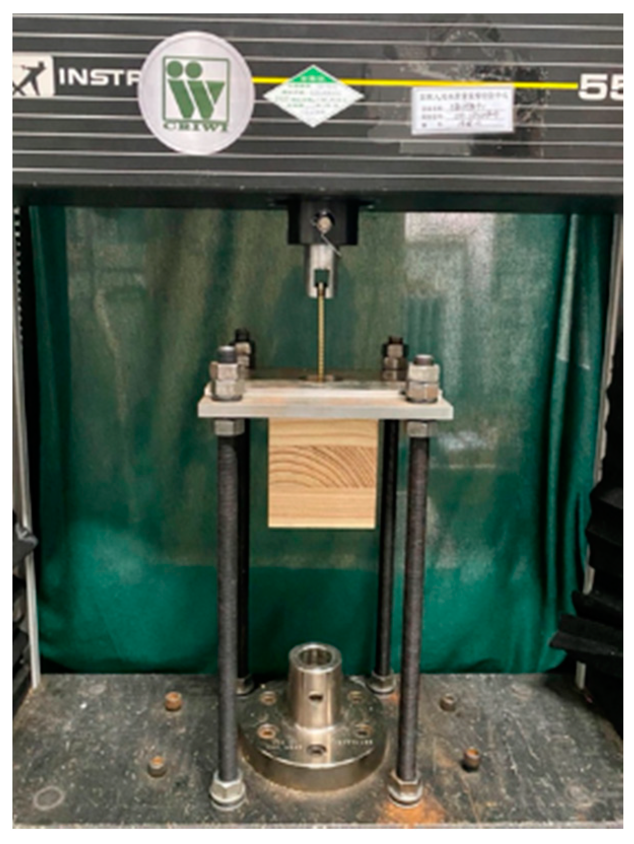
2.2.2. Withdrawal Tests of Self-Tapping Screws in CLT

According to EN 1382 [30], the withdrawal tests were performed under push–pull load conditions on the universal testing machine (Instron 5582) with a constant loading rate of 2 mm/min, as shown in Figure 1. The withdrawal strength was determined following Equation (2)
f ax = F ax , max π × d × l ef
where Fax, max is the maximum load recorded during the test, d is the nominal diameter of STS, and lef is the effective insertion length.

2.2.3. Statistical Analysis

The statistical analysis comprised explorative and descriptive statistical methods, e.g., the estimation of the main statistics for characterizing the location of and variation in test outcomes, as well as box-plots for qualitative comparison of properties from different series.
Moisture content affected the density of wood, thus affecting the withdrawal strength. The density was decreased or increased by 0.5% for every percentage point difference in MC from the reference MC of 12%, according to EN 384 [31]. In order to avoid the influence of different levels of moisture content on the density, the density was calculated with a fixed MC of 12%.
In some tests, the failure mode, such as steel failure of screws in tension, occurred prior to the target failure modes (withdrawal failure); thus, the maximum value of the test was not the withdrawal resistance, but the tensile resistance of STS. These specimen values were eliminated.

3. Results and Discussion

3.1. Screw Performance

To classify the axial tensile performance of the three types of STS, the tensile resistance and strength were determined. Figure 2 shows the typical failure modes. The screws fractured at an arbitrary position along the threaded part, e.g., near the head side (Figure 2a), sharp-cut tip side (Figure 2c), or the middle part (Figure 2b). Differences in failure mode between the three types of screws were not observed [28].
The maximum axial load was taken as the tensile resistance of each screw. The tensile resistance of the STS increased significantly with increasing diameter. This circumstance can be directly deduced from the differences in the associated cross-sections and section module relevant for resisting the external loading. According to the geometric data of the three types of screw (Table 1), the area ratio of the inner (core) cross-section was 16:28:44, which was similar to the tensile resistance (Table 3). Comparing the tensile strength of the three types of STS, no significant differences were found, which can be explained by the same steel grade and hardening processes. These results were similar to those reported by Brandner [28].

3.2. Withdrawal Load-Displacement Behaviour and Failure Modes

Figure 3 shows the typical load-displacement behaviours of density and effective length varieties for the three types of STS under withdrawal tests. The load-displacement curves of withdrawal tests almost had a similar trend, with a linear increase before abrupt failure. The similar feature has been found in the withdrawal test of timber and glued-laminated timber [12]. In the same effective length group, lef = 96 mm, the maximum load increased with the increasing diameter and the increasing density (Figure 3a). In the same density group, ρ12, mean = {0.56–0.60} g/cm3, the maximum load increased with the increasing diameter and the increasing effective length (Figure 3b).
In the initial elastic stage of the loading, the slopes of the lines were close to each other regardless of density variations. No significant differences in the withdrawal stiffness were found in the same density group or effective length group. Comparing the groups d = 8 mm and d = 11 mm, it can be seen that the withdrawal stiffness in screws with a larger diameter was higher than it was with a small diameter (Figure 3).
The typical failure modes of the withdrawal test included the fracture of the STS and the rupture of the CLT. When the withdrawal resistance exceeded the tensile resistance of the STS, the fractures took place at the head (Figure 4d) or the threaded part (Figure 4c) of the STS, and the resistance was nearly equal to the tensile resistance. Since the fractures of the STS itself (steel failure) were independent of timber, the failure modes of the CLT surrounding STS were focused on [12].
The withdrawal failure in CLT was found to be a mix of shear cracks parallel to the grain due to the fiber pull-out (Figure 4a,e–g), and tension perpendicular to the grain (Figure 4b), which was similar to findings in Hübner’s research [32,33]. The bending of fibres and shear cracks occurred around the STS in each layer, while the tension cracks perpendicular to the grain usually occurred at the top layer of the CLT.

3.3. Withdrawal Properties

The statistical analysis of all the withdrawal test groups is summarized in Table 4. The influences and detailed experimental findings on withdrawal properties were analyzed and discussed in the following sections.

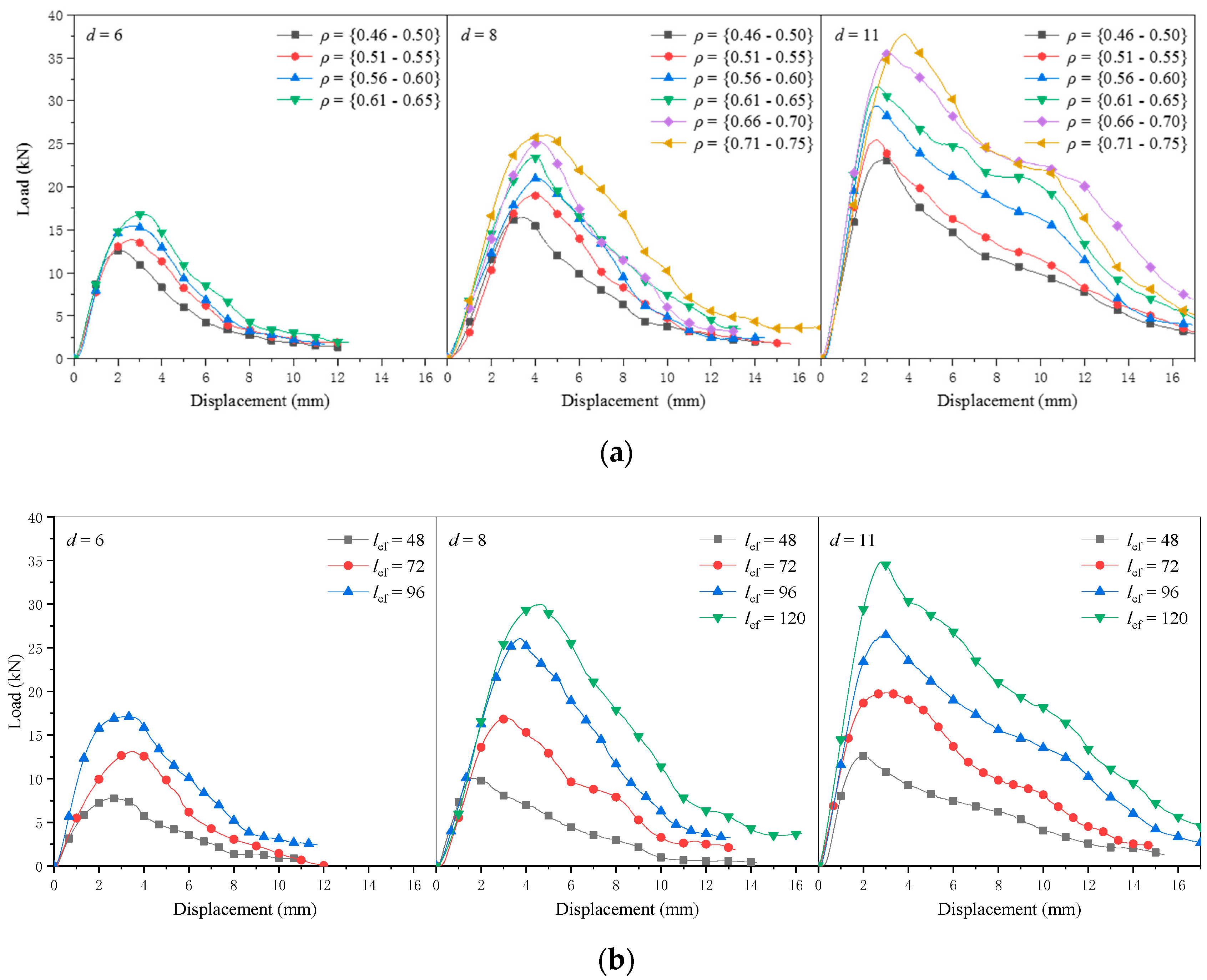
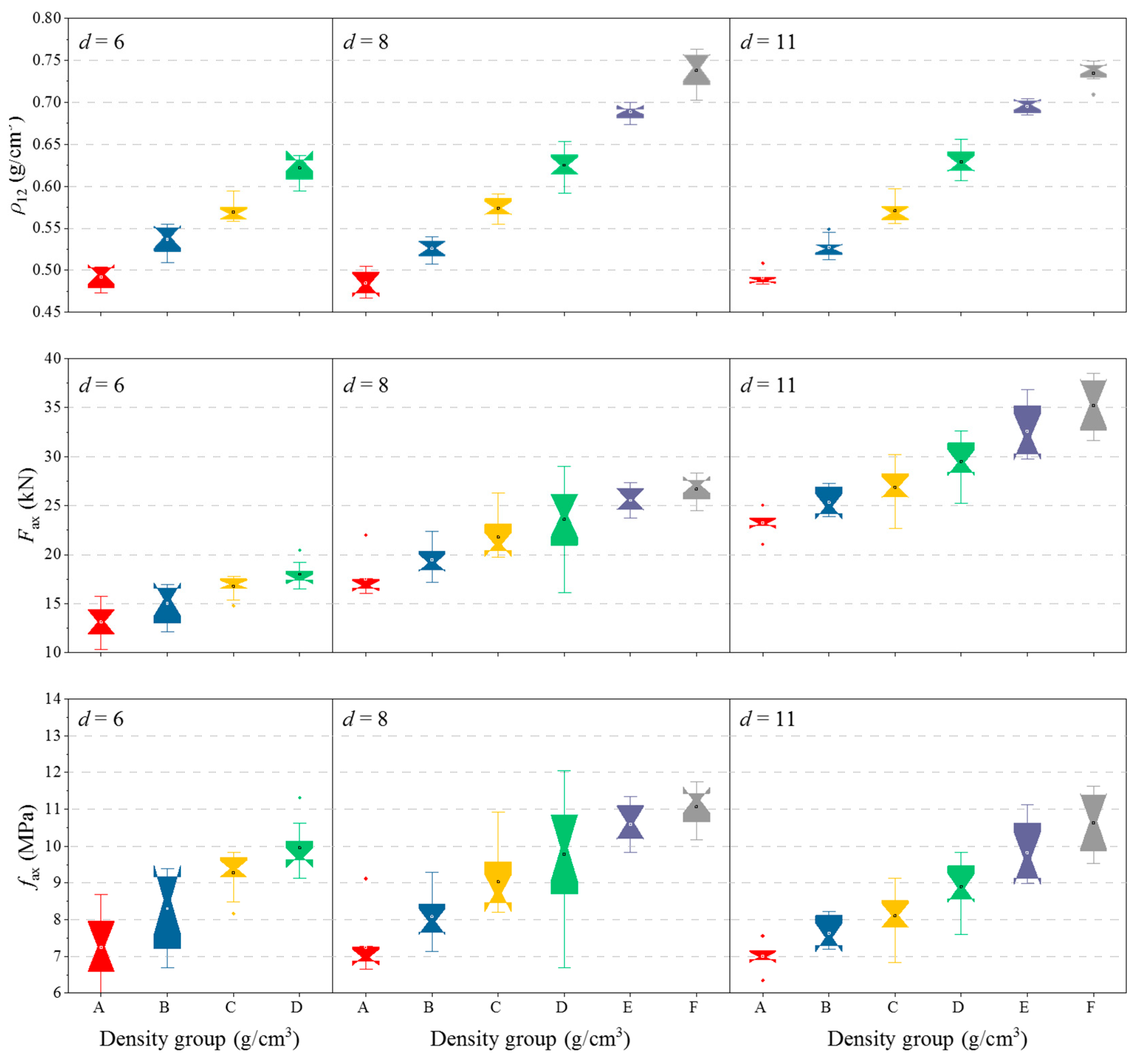
3.3.1. Influence of Density and Screw Diameter on the Withdrawal Properties

The average moisture content (MC) of the CLT in Series Ⅰ was 8.39%, and the average coefficient of variance was 2.37%. The box-plots for the density of the CLT samples are shown in Figure 5 (top). It was found that with a screw diameter of 6 mm and density higher than 0.65 g/cm3, all the specimens failed with screw fracture; the values were nearly the same with the tensile resistance of STS. Therefore, the results of these groups were not included. The coefficient of variation in the mean density, CV (ρ12, mean), was less than 2.8%, as shown in Table 4. The low variation was proof that the density of the specimen was well identified and grouped. The consistency was of great importance to evaluate the influences of density and diameter parameters on the withdrawal properties.
The box-plots of withdrawal capacity for each group are presented in Figure 5 (middle). An increase in withdrawal capacity with increasing diameter and density can be observed. This agrees well with current design equations that the withdraw capacity is a function of diameter and density in EN 1995-1-1 and in technical approvals for STS [34]. Compared with density, the diameter has a more significant influence on withdrawal capacity [28].
The withdrawal strength shown in Table 4 and Figure 5 (below) has a significant increase with increasing density, but a slight decrease with increasing diameter. The same observation was reported by Hübner [33], who tested the axial withdrawal capacity of self-tapping screws with diameters of 6 mm, 8 mm, 10 mm, and 12 mm in hardwoods. Overall, the CV of the withdraw strength of all the tested groups is low due to the control of the experimental design. The mean values of withdrawal strength decrease by an average of 1.8% with the increase in screw diameter from d = 6 mm to d = 8 mm, and further decrease by an average of 6.5% from d = 8 mm to d = 11 mm. When the density increased by 0.05 g/cm3, the withdrawal strength increased by an average of 9.4%. In addition, the larger the diameter, the more obvious the effect.

3.3.2. Influence of Effective Length and Screw Diameter on the Withdrawal Properties

This section focused on the influence of the effective length lef and the diameter d on the withdrawal properties. The test results are summarized in Table 4. The tests were conducted using both three-ply and five-ply CLT specimens. The effective length of lef = 48, 72, and 96 mm were investigated using three-ply CLT specimens, while the effective length at 120 mm was investigated using five-ply CLT specimens. The average moisture content (MC) of the CLT in Series Ⅱ was 8.07%, and the average coefficient of variance was 4.21%.
The density distribution of the CLT specimens in Series Ⅱ is shown in Table 4 and Figure 6 (top). The vast majority of densities were in the range of 0.55 to 0.60 g/cm3, and the mean density (ρ12, mean) was within (0.58 ± 0.01) g/cm3. That tended to identify the influences of parameters on withdrawal properties, e.g., effective length and diameter.
As shown in Figure 6 (middle), it can be seen that the withdrawal capacity increases linearly with increasing effective length and diameter. The withdrawal strength decreases with the increasing diameter of STS, as shown in Figure 6 (below). The withdrawal strength of d = 8 mm was lower than d = 6 mm by an average decrease of 3.1%, but the withdrawal strength decreased by 11.7% from d = 8 mm to d = 11 mm. These indicated that the larger the diameter, the more obvious the drop in withdrawal strength [9], which was similar to findings in Series Ⅰ (Figure 4). When the effective length increased by 24 mm, the withdrawal strength increased by an average of 1.4% (Table 4). The ratios dc/d of the three STS are 0.67 (d = 6 mm), 0.66 (d = 8 mm), and 0.70 (d = 11 mm), respectively, and the first two ratios are lower than the third one. This may be the reason why larger diameters could exacerbate this effect (Figure 6, below).

3.2.3. Prediction Model of Withdrawal Strength of STS in Japanese Larch CLT

The relationship between withdrawal strength f a x and influencing parameters, such as the screw diameter d , effective length l e f , and timber density ρ , is usually described by a multiplicative power regression model of the form [28,35]
f ax = A × d B × l ef C × ρ D
where A, B, C and D are the regression parameters.
The same form was adopted to obtain the regression parameters in Equation (3) using the test data from this study. The obtained formula is expressed as
f ax ,   pred = 0.02 d 0.2 l ef 0.1 ρ 12 1.07
where fax, pred is the predicted withdrawal strength of STS inserted in the side plane of CLT, in MPa; d is the nominal (outer) diameter of STS, in mm; lef is the effective length penetrated in CLT, in mm; ρ12 is the density of the CLT specimen with moisture content of 12%, to avoid the influence of different levels of moisture content on withdrawal strength. The regression parameters (A, B, C, D) were 0.02, −0.2, −0.1, and 1.07, respectively.
Equation (4) describes the prediction model for the withdrawal strength of three commonly used self-tapping screws in CLT made of Japanese larch. The correlation coefficient r is 0.88. Blaβ and Uibel [17] investigated the withdrawal strength of axially loaded self-tapping single screws, with nominal diameters d = 6, 8, and 12 mm, inserted into the side face of CLT. The characteristic approach of the withdrawal strength was present, and the regression parameters of the withdrawal strength approach were 0.14, −0.2, −0.1, and 0.75, respectively. The species of CLT specimens in their research was European spruce (Picea abies) with a mean of approximately 0.45 g/cm3, while the species in this research were Japanese larch with a mean density of around 0.58 g/cm3. The different wood species have micro- and macro-characteristics and density; therefore, the modified equation in this study is developed for Japanese larch for a better agreement [28,32,33].
The verification of this model, as a comparison between test values and predicted values for withdrawal strength of different levels on density, effective length, and diameter is shown in Figure 7. As expected, overall, a better prediction was observed. The model fit very well for CLT with lower density, and the predicted values were a little conservative for CLT with higher density (Figure 7). For configurations with the same density group and different effective length, though the data were slightly scattered, the model fit well (Figure 7).

4. Conclusions

The current research investigated the withdrawal properties of self-tapping screws with axial load in a side plane of CLT made of Japanese larch composed of three or five layers, considering the effects of the diameter of screws, density distribution of CLT, and effective length inserted in CLT. The following conclusions can be drawn:
(1)
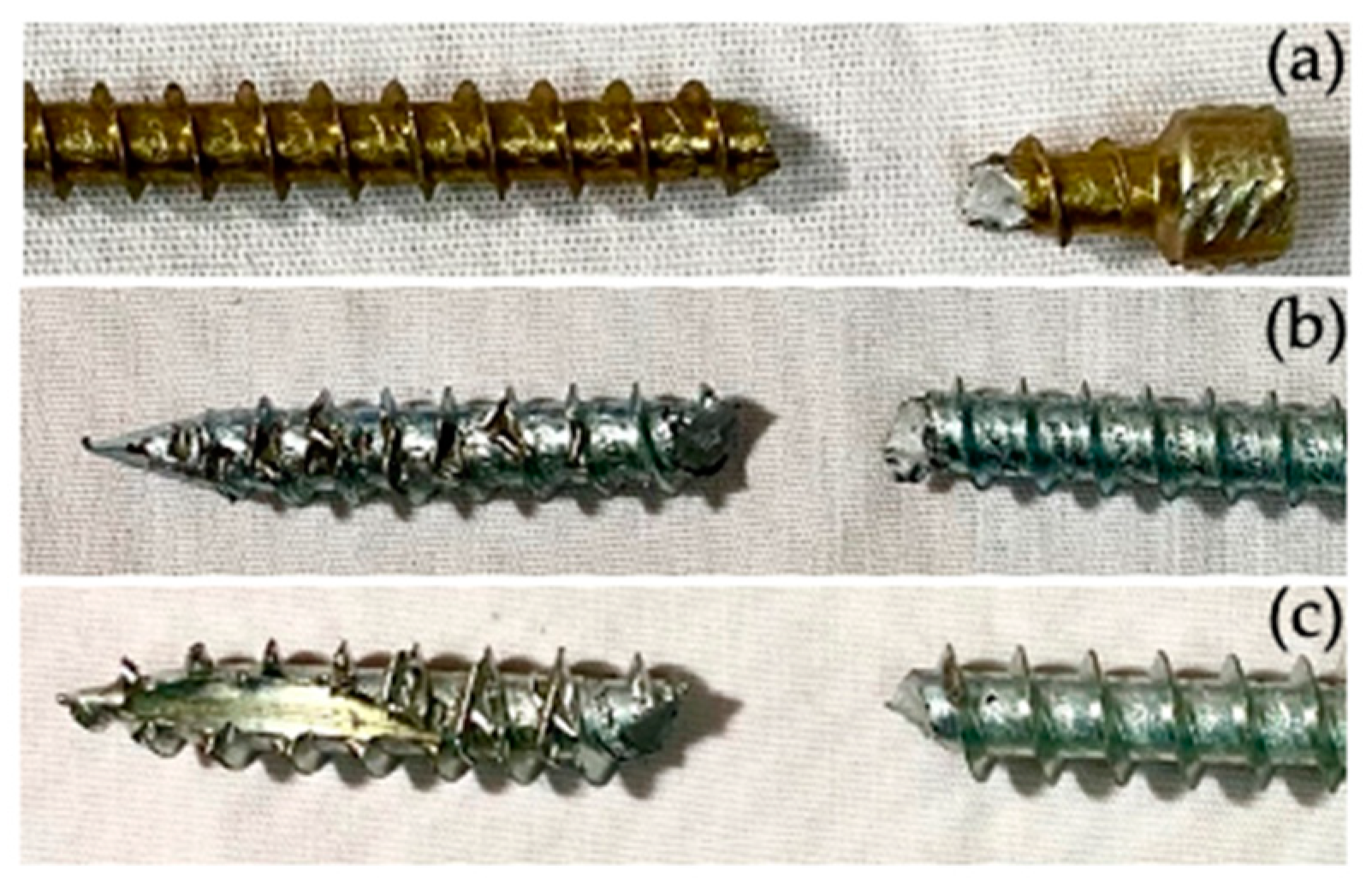
There were no significant differences in the tensile strength of the self-tapping screws of the three diameters (d = 6, 8, and 11 mm), all of which were about 1280 MPa. The typical fracture pattern was steel tension failure at any point of the threaded part;
(2)
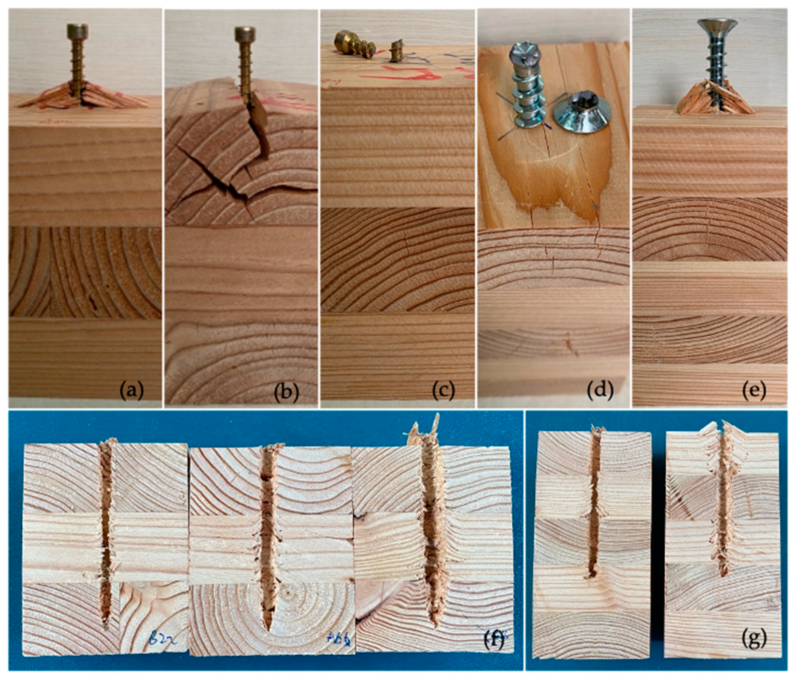
The withdrawal capacity of self-tapping screws was positively related to the density of CLT, as well as the diameter and effective inserted length of the STS. The failure mode of the withdrawal test for STS in CLT was a mix of shear cracks parallel to the grain due to the bending of the fibers and tension perpendicular to the grain;
(3)
The withdrawal strength of self-tapping screws had a power function relationship with density of CLT, diameter, and effective inserted length of STS. In addition, the first influencing factor had a positive effect on the tensile strength, while the remaining two had a negative correlation. The comparison between test values and predicted values obtained reasonable results, while the predicted values were a little conservative for CLT with higher density.
In recent years, COST has taken an action called FP1402 “Basis of Structural Timber Design”—from research to standards, with the aim of overcoming the gap between the broadly available scientific results and the specific information needed by designers, industry, authorities and code committees, and enhancing existing or deriving new methods and design rules for timber structures [36]. In the coming years, the derivation of universal product parameters and design approaches for CLT, as well as the collection and harmonization of methods and parameters to determine the load-carrying of dowel-type fasteners would accelerate the progress of CLT construction, from research to standards.

Author Contributions

Conceptualization, J.X., H.R.; methodology, J.X.; validation, J.X., G.W.; formal analysis, J.X., G.W.; investigation, J.X.; resources, J.X., Y.G.; data curation, J.X., G.W.; writing—original draft preparation, J.X.; writing—review and editing, J.X., G.W.; visualization, J.X.; supervision, S.Z., H.R.; funding acquisition, H.R. All authors have read and agreed to the published version of the manuscript.

Funding

This work was funded by the National Natural Science Foundation of China (31971596).

Institutional Review Board Statement

Not applicable.

Informed Consent Statement

Not applicable.

Data Availability Statement

Not applicable.

Acknowledgments

Our great appreciation goes to the National Engineering Research Center for Wood Industry, the laboratory of Research Institute of Wood Industry at Chinese Academy of Forestry for providing testing materials and machines, and technical staff in assisting this experiment.

Conflicts of Interest

The authors declare no conflict of interest.

References

  1. Gagnon, S.; Pirvu, C. CLT Handbook: Cross-Laminated Timber; FPInnovations: Montreal, QC, Canada, 2011. [Google Scholar]
  2. Brandner, R.; Flatscher, G.; Ringhofer, A.; Schickhofer, G. Cross laminated timber (CLT): Overview and development. Eur. J. Wood Prod. 2016, 74, 331–351. [Google Scholar] [CrossRef]
  3. Brandner, R. Cross laminated timber (CLT) in compression perpendicular to plane: Testing, properties, design and recommendations for harmonizing design provisions for structural timber products. Eng. Struct. 2018, 171, 944–960. [Google Scholar] [CrossRef]
  4. Tuhkanen, E.; Joosep, M.; Gerhard, S. Influence of number of layers on embedment strength of dowel-type connections for glulam and cross-laminated timber. Eng. Struct. 2018, 176, 361–368. [Google Scholar] [CrossRef]
  5. Fink, G.; Jochen, K.; Reinhard, B. Application of European design principles to cross laminated timber. Eng. Struct. 2018, 171, 934–943. [Google Scholar] [CrossRef]
  6. Gong, Y.C.; Wu, G.F.; Ren, H.Q. Block shear strength and delamination of cross-laminated timber fabricated with Japanese la rch. BioResources 2016, 11, 10240–10250. [Google Scholar] [CrossRef] [Green Version]
  7. Blaß, H.J.; Bejtka, I.; Uibel, T. Tragfähigkeit von Verbindungen mit Selbstbohrenden Holzschrauben mit Vollgewinde; KIT Scientific Publishing: Karlsruhe, Germany, 2006. [Google Scholar]
  8. Polastri, A.; Angeli, A.; Gianni, D.R. A new construction system for CLT structures. In Proceedings of the World Conference on Timber Engineering (WCTE), Quebec City, QC, Canada, 10–14 August 2014. [Google Scholar]
  9. Polastri, A.; Giongo, I.; Angeli, A.; Brandner, R. Mechanical characterization of a prefabricated connection system for cross laminated timber structures in seismic regions. Eng. Struct. 2018, 167, 705–715. [Google Scholar] [CrossRef]
  10. Kraler, A.; Kögl, J.; Maderebner, R.; Flach, M. Sherpa-clt-connector for cross laminated timber (CLT) elements. In Proceedings of the 13th World Conference on Timber Engineering (WCTE2014), Quebec City, QC, Canada, 10–14 August 2014. [Google Scholar]
  11. Schickhofer, G.; Bogensperger, T.; Moosbrugger, T. BSPhandbuch: Holz-Massivbau-Weise in Brettsperrholz—Nachweise auf Basis des Neuen Europäischen Normenkonzepts; Verlag der Technischen Universität Graz: Graz, Austria, 2010. (In Germany) [Google Scholar]
  12. Ringhofer, A.; Brandner, R.; Blaß, H. Cross laminated timber (CLT): Design approaches for dowel-type fasteners and connections. Eng. Struct. 2018, 171, 849–861. [Google Scholar] [CrossRef]
  13. Grunwald, C.; Vallée, T.; Fecht, S.; Bletz-Muehldorfer, O.; Diehl, F.; Bathon, L. Rods glued in engineered hardwood products part I: Experimental results under quasi-static loading. Int. J. Adhes. Adhes. 2019, 90, 163–181. [Google Scholar] [CrossRef]
  14. Mohammad, M. Connections in CLT assemblies. In Proceedings of the Cross Laminated Timber Symposium, Vancouver, BC, Canada, 8–9 February 2011. [Google Scholar]
  15. Sydor, M. Geometry of wood screws: A patent review. Eur. J. Wood Prod. 2019, 77, 93–103. [Google Scholar] [CrossRef] [Green Version]
  16. Blaß, H.J.; Uibel, T. Tragfähigkeit von Stiftförmigen Verbindungsmitteln in Brettsperrholz; Karlsruher Berichte zum Ingenieurholzbau, Band 8; Universitätsverlag Karlsruhe: Karlsruhe, Germany, 2007; (In Germany). ISBN 978-3-86644-129-3. [Google Scholar]
  17. Uibel, T.; Blaß, H.J. Load carrying capacity of joints with dowel type fasteners in solid wood panels. In Proceedings of the 39th Meeting on CIB Working Commission W18–Timber Structures, Florence, Italy, 28–31 August 2006. [Google Scholar]
  18. Uibel, T.; Blaß, H.J. Joints with dowel type fasteners in CLT structures. In COST Action FP1004, Focus Solid Timber Solutions, Proceedings of the European Conference on Cross Laminated Timber (CLT), Graz, Austria, 21–22 May 2013; Harris, R., Ringhofer, A., Schickhofer, G., Eds.; The University of Bath: Bath, UK, 2013. [Google Scholar]
  19. Uibel, T.; Blaß, H.J. Edge joints with dowel type fasteners in cross-laminated timber. In Proceedings of the 40th Meeting on CIB Working Commission W18–Timber Structures, Bled, Slovenia, 28–31 August 2007. [Google Scholar]
  20. Ellingsbo, P.; Malo, K.A. Withdrawal capacity of long self-tapping screws parallel to the grain direction. In Proceedings of the World Conference Timber Engineering, Auckland, New Zealand, 15–19 July 2012. [Google Scholar]
  21. Ringhofer, A.; Grabner, M.; Silva, C.V.; Branco, J. The influence of moisture content variation on the withdrawal capacity of self-tapping screws. Holztechnologie 2014, 55, 33–40. [Google Scholar]
  22. Silva, C.; Branco, J.M.; Ringhofer, A.; Lourenço, P.B.; Schickhofer, G. The influences of moisture content variation, number and width of gaps on the withdrawal resistance of self-tapping screws inserted in cross laminated timber. Constr. Build. Mater. 2016, 125, 1205–1215. [Google Scholar] [CrossRef] [Green Version]
  23. Pirnbacher, G.; Brandner, R.; Schickhofer, G. Base parameters of self-tapping screws. In Proceedings of the International Council for Research and Innovation in Building and Construction, Working Commission W18-Timber Structures, Meeting, Dubendorf, Switzerland, 24–27 August 2009. [Google Scholar]
  24. Ringhofer, A.; Brandner, R.; Schickhofer, G. Withdrawal resistance of self-tapping screws in unidirectional and orthogonal layered timber products. Mater. Struct. 2015, 48, 1435–1447. [Google Scholar] [CrossRef]
  25. Abukari, M.H.; Coté, M.; Rogers, C.; Salenikovich, A. Withdrawal resistance of structural screws in Canadian glued laminated timber. In Proceedings of the World Conference Timber Engineering, Auckland, New Zealand, 15–19 July 2012; pp. 134–143. [Google Scholar]
  26. Stamatopoulos, H.; Malo, K.A. Withdrawal stiffness of threaded rods embedded in timber elements. Constr. Build. Mater. 2016, 116, 263–272. [Google Scholar] [CrossRef]
  27. Stamatopoulos, H.; Malo, K.A. Withdrawal capacity of threaded rods embedded in timber elements. Constr. Build. Mater. 2015, 94, 387–397. [Google Scholar] [CrossRef] [Green Version]
  28. Brandner, R.; Ringhofer, A.; Reichinger, T. Performance of axially-loaded self-tapping screws in hardwood: Properties and design. Eng. Struct. 2019, 188, 677–699. [Google Scholar] [CrossRef]
  29. Standardization Administration of the P.R.C. GB 27704. Steel Nails; Standardization Administration of the P.R.C.: Beijing, China, 2011. [Google Scholar]
  30. European Committee for Standardisation GEN. BS EN 1382. Timber Structures-Test Methods-Withdrawal Capacity of Timber Fastener; European Committee for Standardisation GEN: Bruxelles, Belgium, 2016. [Google Scholar]
  31. European Committee for Standardisation GEN. BS EN 384. Structural Timber. Determination of Characteristic Values of Mechanical Properties and Density; European Committee for Standardisation GEN: Bruxelles, Belgium, 2004. [Google Scholar]
  32. Hübner, U.; Rasser, M.; Schickhofer, G. Withdrawal capacity of screws in European ash (Fraxinus excelsior L.). In Proceedings of the 11th World Conference on Timber Engineering, Trentino, Italy, 20–24 June 2010; pp. 241–250. [Google Scholar]
  33. Hübner, U. Withdrawal strength of self-tapping screws in hardwoods. In Proceedings of the 46th CIB W18 Meeting, Vancouver, BC, Canada, 26–29 August 2013. [Google Scholar]
  34. Brandner, R.; Ringhofer, A.; Grabner, M. Probabilistic models for the withdrawal behavior of single self-tapping screws in the narrow face of cross laminated timber (CLT). Eur. J. Wood Prod. 2017, 76, 13–30. [Google Scholar] [CrossRef] [Green Version]
  35. Stepinac, M.; Cabrero, J.; Ranasinghe, K.; Kleiber, M. Proposal for reorganization of the connections chapter of Eurocode 5. Eng. Struct. 2018, 170, 135–145. [Google Scholar] [CrossRef]
  36. COST Action FP1402 “Basis of Structural Timber Design”—From Research to Standards. Available online: https://webarchiv.typo3.tum.de/TUM/costfp1402/en/home/index.html (accessed on 23 April 2021).
Figure 1. Setup for withdrawal test.
Forests 12 00524 g001
Figure 2. Typical fracture patterns from steel tension failure (ac): (a) STS fracture at the threaded part near head side; (b) STS fracture at the threaded part in the middle; (c) STS fracture at the threaded part near sharp-cut tip side.
Forests 12 00524 g002
Figure 3. Typical withdrawal load-displacement curves of three types of STS with different effective length (a) in four or six density groups (b).
Forests 12 00524 g003
Figure 4. Typical failure patterns of withdrawal test for STS and CLT, such as row shear of CLT surrounding STS (a,e,f,g), splitting and tension cracks perpendicular to grain of CLT in the first layer (b), and steel tension failure of STS (c,d).
Forests 12 00524 g004
Figure 5. Withdrawal property for three types of STS in CLT with six density groups, A = (0.46–0.50) g/cm3, B = (0.51–0.55) g/cm3, C = (0.56–0.60) g/cm3, D = (0.61–0.65) g/cm3, E = (0.66–0.70) g/cm3, and F = (0.71–0.75) g/cm3.
Forests 12 00524 g005
Figure 6. Density distribution of CLT specimens for different efficient length of STS inserted in CLT.
Forests 12 00524 g006
Figure 7. Comparison between test values and predicted values for withdrawal strength on density (a), effective length (c), and diameter (b, d). The oblique solid line is an auxiliary line with no substantive meaning.
Forests 12 00524 g007aForests 12 00524 g007b
Table 1. Geometry and main features of three types of screws.
GroupNominal Diameter d (mm)Core Diameter dc (mm)dc/dThread Pitch (mm)Tip TypeHead Type
DrillingSharp CuttingCylindricalCountersunk with Robs
Forests 12 00524 i001 Forests 12 00524 i002 Forests 12 00524 i003 Forests 12 00524 i004
STS0664.00.673.78
STS0885.30.664.05
STS11116.60.605.58
Table 2. Overview of test parameters.
ParameterSeries ⅠSeries Ⅱ
STS diameter, d (mm)6, 8, 116, 8, 11
CLT density, ρ (g/cm3)0.45–0.50, 0.51–0.55, 0.56–0.60, 0.61–0.65, 0.66–0.70, 0.71–0.750.56–0.60
Effective length, lef (mm)9648, 72, 120
Pre-drillingYesYes
Thread-fibre angle, α (°)90°90°
Sample number, n (-)192108
Table 3. Tensile resistance and strength of self-tapping screws.
Diameter d (mm)Number n (-)Tensile ResistanceTensile Strength
Ftens,mean (kN)CV (%)ftens,mean (MPa)CV (%)
61116.19.212819.2
81128.22.912802.8
111144.26.112905.8
Table 4. Statistics of withdrawal strength for three types of STS.
GroupNominal Diameter d (mm)Effective Length lef (mm)Density (CV) ρ12,mean (g/cm3)Withdrawal Strength (CV) fax, mean (MPa)
A-6-96 *6960.49 (2.2%)7.25 (12.2%)
B-6-966960.54 (2.6%)8.30 (9.6%)
C-6-966960.57 (2.3%)9.28 (7.4%)
D-6-966960.62 (1.4%)9.96 (2.3%)
A-8-968960.48 (2.8%)7.25 (10.1%)
B-8-968960.53 (2.0%)8.08 (7.9%)
C-8-968960.57 (2.0%)9.04 (9.0%)
D-8-968960.63 (2.1%)9.78 (9.4%)
E-8-968960.69 (1.3%)10.59 (4.6%)
F-8-968960.74 (2.4%)11.06 (3.8%)
A-11-9611960.49 (0.6%)7.01 (5.1%)
B-11-9611960.53 (2.2%)7.64 (7.9%)
C-11-9611960.57 (2.2%)8.11 (7.9%)
D-11-9611960.63 (2.1%)8.90 (10.7%)
E-11-9611960.69 (1.8%)9.83 (6.2%)
F-11-9611960.73 (2.0%)10.67 (9.5%)
C-6-486480.59 (2.1%)9.25 (12.0%)
C-6-726720.58 (3.8%)9.25 (9.6%)
C-8-488480.59 (2.8%)8.86 (13.9%)
C-8-728720.57 (2.9%)9.01 (12.5%)
C-8-12081200.58 (1.6%)9.23 (5.9%)
C-11-4811480.58 (2.8%)7.64 (10.5%)
C-11-7211720.57 (2.9%)8.01 (7.4%)
C-11-120111200.58 (1.4%)8.17 (12.1%)
* The groups were named by density group-screw diameter-effective length.
Publisher’s Note: MDPI stays neutral with regard to jurisdictional claims in published maps and institutional affiliations.

