Abstract
This paper presents the development of a microwave puffed wood (MPW) with novel and unique structural features in its internal structure that are based on natural wood (NW). The focus of the research was on the comprehensive visualization of the structural characteristics of MPW from the macroscopic to the microscopic scale followed by an exploration of its impregnation capabilities. The results showed that the volume of MPW increased by about 9% compared to NW due to the presence of a large number of cracked cavities. The CT images indicated that there was a significant difference between the macroscopic cracks produced by microwave processing and the natural cracks in the wood. The mercury intrusion test results showed that macro-pores increased while the micro-pores decreased in the MPW compared to in the NW. The MPW showed good fluid permeability and liquid absorption performance. The phenolic resin penetration rate of the MPW was about 20 times that of the NW, and the material absorption was more than 2 times that of the NW. The crack space enabled the MPW to serve as a fluid transportation and a storage warehouse. MPW is a super container based on natural materials. It has broad potential in more fields, such as in wood composite materials.
1. Introduction
Wood is widely used in human life. Thanks to its anisotropic structure and rich porous structure, natural wood has a high strength-to-weight ratio and is used for various functionally modified materials [1,2,3,4]. Nowadays, there are fewer precious wood resources with excellent strength, and the fast-growing wood from plantations is gradually dominating the wood product market due to abundant resource reserves [5,6,7,8,9]. Planted forests generate sufficient timber yields, but they are generally of low strength and are difficult to use in various parts of human life. Plantation wood with enhanced functional modification possesses large market potential [10,11,12,13,14,15]. Scientific researchers and engineers in the wood industry have made considerable attempts to improve the quality of plantation wood over the past few years, making it suitable for high-strength and high-end applications [16,17,18,19,20,21,22,23]. Among various attempts, improving the impregnation capacity of wood is an important way to enhance the strength of plantation wood and to enable its effective value-added applications [24,25,26,27,28].
In our previous works, we developed a new material based on plantation wood. This material is called microwave puffed wood (MPW), and it has the structural properties and almost all of the advantages of natural wood (NW). Moreover, this new material is equipped with a more spacious structure, which is expected to solve the problem of the functional modifications resulting from uneven wood impregnation. With regard to microwave treatment, NW is processed using microwave equipment to produce a new anisotropic structure inside of the wood, but this does not affect the overall appearance of the wood. When the moisture content of the wood is controlled within a certain range, the wood is placed on the conveyor belt of the high-energy microwave equipment and passes through the microwave launching field at a uniform speed. The microwave field will quickly have an effect on the wood tissue, and the water and moisture in the tissue will move at high speeds instantaneously, generating a lot of heat and water vapor [29,30]. The water vapor breaks through the clogged pits and vessel elements in the wood structure, and the weak location of the wood tissue is separated or destroyed instantly. Water vapor creates regularly distributed crack areas inside of the wood. These new spatial structures are gaps that are created by the separation of the cell walls. From the perspective of the whole piece of wood, there are a large number of such gaps that are created, and the wood seems to expand instantaneously.
In this research, we observed the structural characteristics of MPW through multiple tests, including computer tomography (CT) image acquisition, mercury intrusion experiments, phenolic resin penetration, etc., to establish a thorough understanding of the unique structures of MPW, which presumably plays a vital role in exploring its further applications. The paper thus determines the impregnation capability of MPW by conducting phenolic resin and dye penetration experiments that aim to indicate that great potential that MPW possesses in terms of wood modification and functionalization as well as in the development of new woody materials.
2. Materials and Methods
2.1. Sample Preparation
The wood used in the experiment was Radiata Pine (Pinus radiata D.Don) from New Zealand, and samples with no natural defects in appearance were selected. The wood samples were stripped of bark. According to the size requirements of the microwave equipment for the sample, the wood was sawed to a size of 1500 mm × 200 mm × 80 mm. There were 20 samples in total. All of the samples were processed under the same conditions. A sample with a length of 300 mm was reserved for each piece of wood as a blank control, and the remaining wood with a length of 1200 mm was used as the test material.
Wood moisture content (MC) was adjusted to 40% prior to the treatment. The moisture content determination method adopted ISO 13061-1-2014 Physical and mechanical properties of wood—Test methods for small clear wood specimens—Part 1: Determination of moisture content for physical and mechanical tests.
The tunnel-type microwave processing equipment is shown in Figure 1a. The wood was treated in tunnel-type wood microwave processing equipment, the microwave power was 140 kWh/m3, and the wood feeding speed was 1 m/min. Samples were recorded with dimensional data and were weighed before and after microwave treatment. The prepared MPW and the reserved blank control were naturally dried to an equilibrium moisture content of 11.4%.
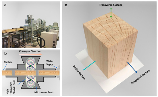
Figure 1.
Preparation of microwave puffed wood (MPW). (a) Image of tunnel-type microwave processing equipment; (b) schematic diagram of the principle of the microwave puffing treatment process; (c) Three-dimensional image of a piece of MPW (97 mm × 78 mm × 68 mm).
2.2. Comparison of Wood Macro Characteristics
MPW and NW from the same piece of wood were used as an experimental group. MPW and NW were cut into a size of 150 mm × 60 mm × 60 mm. There were three groups in total. Each group of materials contained one piece of MPW and two pieces of NW.
For the NW, one piece was wrapped in plastic film and was placed indoors at 20 °C to prevent natural cracking, and the other piece was placed in an outdoor environment.
The outdoor environment had an average temperature of −1.5 °C, an average wind speed of 2.5 m/s, and an average relative humidity of 50%. The wood remained under the influence of sunlight and humidity for a month, and natural cracking tends to occur in December in Beijing.
The macro characteristics of MPW, NW, and cracked NW were observed by photographing the appearance of three sides of the preserved wood.
2.3. CT Image Acquisition
In order to obtain the internal structure of wood, CT scans were performed. The MPW was sawed to a size of 300 mm × 200 mm × 80 mm, and it was scanned of the analyze the structural features of the MPW. The MPW, NW, and cracked NW samples that were 150 mm × 60 mm × 60 mm in size were scanned to distinguish the internal structure of the three types of wood.
The equipment model was CT450-TY-ICT (Institute of High Energy Physics Chinese Academy of Sciences, Beijing, China), the equipment spatial resolution was 160 μm, and the X-ray source voltage was 450 kV. By analyzing the CT tomographic image data, the distribution law information of the fractures was obtained. CTvox, 3D Slicer, and 3D Builder programs were used to process CT information in order to obtain the three-dimensional model of the wood structure and to obtain a three-dimensional model of the crack distribution, respectively. Macro photography and CT scan are capable of capturing the structure features of wood samples that are larger than 200 μm.
Specifically, from one end of the transverse surface of the wood sample, section information was extracted every 10 mm along the axial direction, and a total of 20 sections were extracted for analysis. From the tangential surface of the wood, the distance between adjacent cracks was observed by extracting section information every 10 mm from one end of the wood, and a total of 20 sections were extracted for analysis. The average value of the maximum vertical distance and the minimum vertical distance between the two cracks was taken as the gap between the two cracks. The angle between the extension lines of the two cracks should be taken as the angle between the two cracks. The maximum value of the included angle, the minimum value of the included angle, and the average of the included angle that account for most of the adjacent cracks at different distances from the pith of the wood on the cross section should be calculated. The maximum and minimum spacing between adjacent cracks at different distances from the end of the wood on the cross section and chord section and the average of the spacing values that account for the most should be calculated.
2.4. Ultra-Depth of Field Three-Dimensional Microscope Image Acquisition
The name of the equipment is VHX-6000 (KEYENCE, Osaka, Japan). The MPW was first sawed and cut into a size of 10 mm × 10 mm × 10 mm. Before microscopic observation, a flat surface was created on the observation surface using a microtome. The flattened cross sections were observed under the three-dimensional microscope by switching the 100×, 200×, and 500× objectives. The ultra-depth of the field microscope is able to examine the structure of wood that is larger than 10 μm. Under the microscope, the tracheid, ray structure, pore structure and microscopic cracks of wood can be clearly observed.
2.5. Mercury Intrusion Experiment
In order to further test the pore characteristics of wood, a mercury intrusion experiment was performed. The wood was sawed into a size of 10 mm ×10 mm × 10 mm. A high-performance automatic mercury porosimeter AutoPore IV 9500 with a test accuracy of 0.005 μm was used to obtain pore size distribution, total pore volume, and other information. The pore size test range was 0.005 μm to 1000 μm, and the reported pressure range was 1379 Pa to 206,850,000 Pa. In the mercury intrusion test, the pore size information and the number of holes in the wood are obtained by changing the mercury intrusion pressure. Mercury can only penetrate into pores with a pore diameter that is smaller than 1000 μm. The pore filling sequence is large pores, mesopores, and small pores. By comparing the different feedback of the NW and MPW from the mercury intrusion experiment, the unique microstructure of MPW can be further scrutinized.
2.6. Phenolic Resin Penetration
In order to characterize the influence of the special structure of MPW on fluid penetration, a phenolic resin (phenol-formaldehyde resin) penetration experiment was conducted. In this work, a higher solid content resin was used to test the penetration of high-viscosity modifiers. MPW and NW were sawed to a size of 300 mm × 80 mm × 80 mm, and the samples dried to MC 0% (drying temperature 103 °C, drying time 72 h). The solid content of the phenolic resin was 45%, the viscosity was 40 MPa·s, and the experimental temperature was 20 °C. The soaking time gradient was set as 10 min, 30 min, 1 h, 3 h, 6 h, 12 h, 24 h, and 48 h. After soaking, the samples were dried at 103 °C for 36 h to obtain wood that was absolutely dry and with the impregnated resin completely cured. The dry wood was then sawed along the axial center line of the radial section for the observation of the resin distribution. The resin permeation experiments not only evaluated the liquid absorbing performance but also provided information on material flow path and storage of the expanded timber.
2.7. Dye Penetration
Dye liquor has a relatively low solid content and viscosity. The dye liquor penetration experiment is used to test the fluid penetration in wood dyeing and other scenarios. The wood was sawed to a size of 300 mm × 80 mm × 80 mm. An amount of 13.5 g of brown dye powder was dissolved in 0.01 m3 of deionized water to obtain a low-concentration dye solution. The dye liquor and wood were put into the thermal cycle dyeing container; the experiment temperature was 90 °C, the experiment time is 36 h, and a water supply device was equipped for the experiment. A drying process was conducted after the penetration period was completed, the drying temperature was 103 °C, and the drying time was 24 h. A 290 mm × 70 mm × 70 mm rectangular parallelepiped was taken from the inner parts of the sample to observe the distribution of the dye solution inside of the wood.
3. Results
3.1. Influence of Microwave Treatment
According to preliminary experiments, MPW with abundant cracks can be obtained when the moisture content of the wood is 30–50%. A moisture content that is too high will prevent the wood from cracking. If the moisture content is too low, then wood is at risk of carbonization and burning. The crawler conveyor enables the wood with an unlimited length and size to be continuously fed in order to obtain a uniform microwave field effect.
As shown in Figure 1b, the moisture inside of the wood moved rapidly and thus released energy under microwave action. The blocked area inside of the wood burst instantly, the weak location cracked, and macroscopic cracks formed, which were accompanied by a large amount of water vapor gushing out of the wood. On average, each piece of wood lost about 30% of its weight after the treatment. For instance, a piece of wood with a moisture content of 40% and a weight of 8.96 kg lost 2.6 kg of water during the treatment. Due to the formation of cracks, the volume of the wood expanded by approx. 9% while the weight was reduced.
As shown in Figure 1c, a large number of longitudinally distributed incomplete fracture gaps can be observed on the transverse surface and tangential surface of the wood. Preliminary observations suggested that the radially distributed cracks on the transverse surface might have some regularity, and the wood could have produced a new structure.
3.2. Material Macro Characteristics
To prove that MPW can be classified as a new type of wood material that is different from NWT after microwave treatment, a set of experiments aiming to distinguish the MPW and untreated NW were conducted here. Computer tomography (CT) scans were performed on both the MPW and the control samples to obtain a detailed internal structure, and the results were shown in Figure 2. It can be observed in Figure 2a that the wood reconstructed by CT exhibited clear wood structure and density distribution, in which the lighter color referred to the parts with relatively higher density, such as latewood and the knots of the wood, while the darker color was from the components with a relatively low density, such as earlywood and the pith of the wood. In the upper part of Figure 2a (i.e., MPW), it can be seen that microwave treatment added a crack structure to the original wood, and the cracks and cavities are shown in black or nearly black.
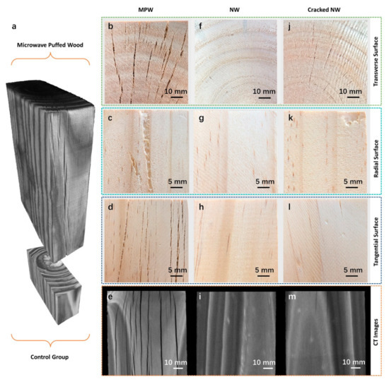
Figure 2.
Comparison of MPW and control group.
NW cracks naturally in an environment with unsuitable humidity and temperature conditions and produces cracks similar to those in MPW. From Figure 2b,j, it can be seen that the natural cracks on the transverse surface of the wood were distributed in rays with slight cracking. The MPW produced gaps due to instantaneous expansion, and the small cracks were distributed between the large gaps. Figure 2c,d shows a longitudinal crack distribution in the MPW, indicating that the interior of the wood underwent uniform and regular changes during microwave treatment. Figure 2k,l shows that the naturally cracked wood only had a few small cracks in the areas that were exposed to the external environment. Figure 2e,m are the CT images of the transverse surface of MPW and naturally cracked wood. Only a few cracks with shallow longitudinal depth were observed on the tangential surface of the naturally cracked wood. Observations from the inside of the material further proved the differences between the natural cracks and the cracks or gaps caused by microwave treatment.
In the schematic diagrams shown in Figure 2b–e, the gaps produced in the wood after microwave treatment were not completely penetrated in three directions, and each gap had an adjacent gap in the same direction. The ends of the cracks were staggered with each other. There was a connection between the wood tissues on both sides of the crack to maintain the stability of the overall structure. The unique gap structure made the MPW full of cracks and look fragile, but it maintained a certain level of structural integrity.
3.3. Crack Distribution Law
The most evident difference between the MPW and NW in the macroscopic structure was the existence of crack spaces with a regular distribution. CT images can provide information about cross sections on the entire wood. In this work, a cross section was extracted in order to observe the crack distribution at different positions on the same surface, and multiple surfaces were then extracted for longitudinal comparison. In Figure 3a, taking the wood pith as the starting point, as the position of the crack became farther away from the wood pith, the angle between two adjacent cracks became smaller and gradually showed a parallel trend. The statistics of this phenomenon are shown in Figure 3f. In the area from the medulla core to the first growth ring, the smallest angle between adjacent cracks was 10.0°, the largest angle was 35.0°, and the angle representing the majority was approx. 20.0°. In the area from the first growth ring to the fourth growth ring, these three angles were 3.0°, 15.0°, and 10.0°, respectively. In the area from the fourth growth ring to the eighth growth ring, the angles were 3.0°, 6.0°, and 5.0°, respectively. According to the statistics of multiple groups of adjacent cracks, it was found that the extension lines of the adjacent cracks intersected at or near the pith of the wood.
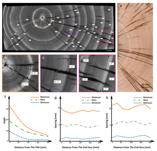
Figure 3.
The distribution of cracks in MPW. (a) CT image of the transverse surface of the MPW; (b–d) pictures of the cracks at the pith, the third growth ring, and the eighth growth ring; (e) transverse surface image of MPW; (f) observed in transverse direction, starting from the pith of the wood, the variation of the angle between adjacent cracks along the radial direction of the wood; (g) observed in transverse direction, the variation of the distance between adjacent cracks in the axial direction of the wood; (h) observed in tangential direction, the variation of the distance between adjacent cracks in the radial direction of the wood.
With respect of the size information of the cracks on the cross section of the wood, the observable cracks had a radial length of 5 mm to 60 mm, the maximum width of the wider cracks was approx. 2.5 mm, and that of the smaller cracks was approx. 0.1 mm. It can be analyzed from Figure 3g that the crack morphology of each transverse surface of the MPW was rather stable, indicating that the longitudinal distribution of cracks in the wood was straight and regular. Although the angles of the adjacent cracks at different positions of the cross section varied, their spacing was not much different. The maximum spacing, minimum spacing, and spacing representing the largest proportion were nearly the same in different sections. The spacing between adjacent cracks was between 1 mm and 10 mm, and the spacing that accounts for most of the cracks was approx. 5 mm.
The cracks on the tangential surface were distributed longitudinally, and the adjacent cracks were nearly parallel. The maximum width of wider cracks was approx. 2.5 mm, and the maximum width of the smaller cracks was approx. 0.1 mm. The axial length of the cracks ranged from 5 mm to 150 mm. For the cracks with a maximum slit width below 0.5 mm, their longitudinal length was approx. 5 mm to 50 mm, while the cracks with a maximum slit width above 0.5 mm had a longitudinal length between 20 mm and 150 mm. Figure 3h presents the variation of the distance between adjacent cracks on the tangential surface. The spacing that accounted for the most cracks was approx. 5 mm. The statistical data presented in Figure 3h was consistent with the spacing data of the adjacent cracks on the cross sections (Figure 3f). Summarizing the macroscopic distribution of the cracks, it can be concluded that the MPW possesses an anisotropic structure with orderly arranged cracks.
3.4. Mercury Intrusion Experiment
MPW showed different characteristics from NW at the macroscopic scale and could also have different performance at the microscopic scale. Since the resolution of macro photography and CT scanning is relatively low, a three-dimensional microscope with super depth of field was used to examine the microscopic structure of the wood. Because the MPW has a lot of cracks, the slice preparation for traditional microscope observation can easily cause the sample to break. The ultra-depth of the field microscope is more suitable for the microscopic observation of the MPW. As shown in Figure 4a, the crack section of the MPW was neat and smooth, and the sample did not need to be cut flat for the examination. Under 100× magnification, the torn band-shaped wood structure and the complete wood ray tissue can be seen. In Figure 4b, the pits of the wood tracheids, the pits in the cross-field, and the shed radial resin channels containing brown resin were observed after the toning treatment. Figure 4c,d are images of the MPW cross sections. The ends of the cracks, partially broken tissues, and complete crack sections can all be clearly observed.
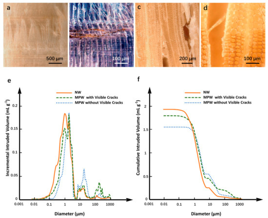
Figure 4.
Microscopic characteristics of MPW. (a) The crack under the microscope at 100× (the diameter section of the wood passing through the crack); (b) the crack under the microscope (with coloring treatment); (c,d) cross section of wood; (e,f) typical curves for incremental and cumulative intruded volume versus pore diameter in the mercury intrusion test; three different curves represent NW, MPW with visible cracks, and MPW without visible cracks.
Figure 4d contains a great deal of microscopic information regarding the MPW, including the boundary position of the early wood and the late wood and the two groups of adjacent ray structures. The ray tissue on the right was slightly cracked, with most of the ray cells still adhered to the tracheids on both sides, and the widest part of the slit was about 40 μm. The ray tissue on the left was completely cracked, and some ray cells were detached. In the examination area, 150 μm wide cracks that can be seen directly by the naked eye were also observed.
With respect to the smaller pore size range from 0.01 μm to 5 μm, the NW showed a wider mercury increment curve (Figure 4f) and a steeper mercury accumulation curve. This indicates that the main pore structure of the NW consisted of small pores with a pore that was size less than 1 μm, and its mercury absorption was mainly dependent on these tiny pores. The peak value of the mercury increment of MPW appeared at the pore size of approx. 2 μm, the overall peak curve was shifted to the right compared with the NW, and its mercury increment range was narrower. As a result of the microwave treatment, the small pores that were originally responsible for absorbing mercury reduced in number or disappeared, giving rise to the creation of larger crack space. Specifically, multiple micro pores were connected to form larger pores due to the treatment, which was accompanied by the formation of microscopic cracks being created at the same time. For the MPW samples, their curve profiles of the mercury increment were fairly similar throughout the sample, with obvious cracks exhibiting a much lower peak value (Figure 4f), suggesting that tiny cracks and pores were common in the MPW and that these obvious cracks occupied more volume spaces. In Figure 4g, it can also be seen that the NW had about 24% more accumulated mercury than the MPW and that the MPW with no obvious cracks had about 2.5% more mercury accumulation than its counterpart with obvious cracks, indicating that the obvious cracks and the larger pores that cannot retain mercury occupied plenty of space under the same volume. This result is in agreement with the mass measurements, specifically those indicating that the mass of the MPW under the same volume was smaller. The occurrence of cracks caused the volume of the wood to expand.
3.5. Fluid Adsorption Capacity Experiment
In order to prove the application potential of MPW in functional modifications, a set of experiments on liquid impregnated wood were conducted. The solid content of the phenolic resin was adjusted to 45%, allowing the liquid to obtain an immediate viscosity, such that the material would not be absorbed too quickly so that it would be easy to calculate the solid weight gain. Putting the NW and MPW with same specifications into the resin, the MPW performed better than NW in terms of absorption speed and capacity. The radial surface of NW and MPW was soaked in the resin for 10 min and dried until the resin was cured. The NW had almost no deep resin penetration; only a small amount of resin entered into its natural cracks. It was seen that the NW soaked for 24 h had resin penetration along the axial direction. In the MPW, it can be clearly observed that the resin had deeply penetrated along the cracks. As the immersion time increased, the depth of the resin penetration into the MPW became higher, and the penetration gradually reached the cell tissue on the crack-free end surface of the wood. The liquid and solid content of the NW and MPW increased with the increase of the soaking time, but the penetration efficiency of the MPW was much higher than that of the NW. The weight gain of the MPW soaked in resin for 10 min exceeded its NW counterpart that was soaked for 3 h, and the liquid absorption of the MPW rate was approx. 20 times that of NW. After 48 h of soaking, the weight gain of the MPW was about twice that of NW.
Wood possesses fluid penetration channels that are composed of cell tissues, which are of great significance to the physiological activities of trees and the application of timber materials. With the help of capillary action and environmental influence, small wood fluid channels are able to complete the permeation and transportation of fluid in all directions between wood cell tissues, forming a natural fluid permeation network. The simulation diagram of fluid permeation is shown in Figure 5d. The NW and MPW soaked for 24 h both had resin penetrated from their end surfaces, and in the MPW, the resin seeped to both sides of the cracks. These phenomena conformed with the fluid penetration law of wood, and the crack space of the MPW enhanced the penetration effect. The crack space intersected with the surrounding wood cell tissue fluid channel, enabling the fluid in the crack space to be transmitted in the longitudinal, tangential, and radial directions of the wood. The regularly distributed cracks combined with the fluid penetration network within the wood make it a good fluid transfer station and warehouse.
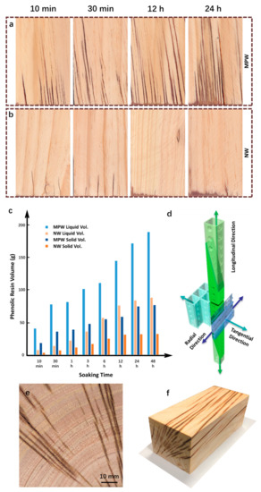
Figure 5.
Fluid adsorption capacity experiments. (a,b) MPW and NW were impregnated in phenolic resin for different amounts of time; (c) The NW and MPW sawn to 300 mm × 80 mm × 80 mm were soaked in phenolic resin, and the relationship between the amount of impregnation and the impregnation time were determined. Liquid Vol. is the increase of phenolic resin glue, and Solid Vol. is the increase of solids after the resin is cured; (d) schematic diagram of the fluid penetration mode of wood cell tissue; (e,f) images of MPW soaked in dye solution for 36 h.
In order to evaluate the penetration characteristics of low-viscosity liquid in the MPW, the MPW was soaked in a brown low-concentration dye solution for 36 h and was dried. Figure 5f showed the diffusion morphology of the dye solution in the MPW after removing the outmost layer. The dye solution diffused into the wood cell tissue at the edge of the crack, and the penetration depth was close to the penetration depth on the outer surface of the wood, approx. 1.5 mm. This result suggests that under normal atmospheric pressure, the inner surface of the crack space played the same role as the outer surface of the wood. The surface area under the same volume, the efficiency of liquid impregnation, and the solid matter retention of the MPW were greatly improved compared to the NW. The penetration and diffusion of the dye solution in the MPW in Figure 5f clearly demonstrates the distribution of the crack space, and the revealed anisotropic distribution characteristics were consistent with previous studies on the distribution law.
MPW has a unique structure and excellent permeability, and fluid materials such as resin can be better impregnated into it. This provides a good foundation for the functional modification of wood by fluid-type modifying substances.
4. Conclusions
In summary, we designed and manufactured wood materials with a new internal structural space. The crack spaces obtained by microwave treatment were distributed anisotropically in a large piece of wood, providing the wood with high fluid penetration efficiency and high capacity. A rich pore structure was clearly observed in the wood, especially in terms of the macro pores and macro cracks from 5 μm to 1000 μm. Due to the large number of cracked cavities, the volume of the MPW increased by about 9% compared to the raw material. In the process of fluid infiltration into the material, the crack space played the role of fluid transportation or the role of a transfer station and storage warehouse. The liquid penetration rate of the MPW was about 20 times that of natural wood, and the material absorption was more than 2 times that of natural wood. The crack space was combined with the fluid penetration network of the wood itself to form a new fluid channel network.
MPW is easy and fast to manufacture, is adjustable in size, is easy to expand, and can be used for large-scale applications. The abundant multi-scale crack space allows the wood to be easily impregnated and filled with various fluid materials, and the impregnating materials are distributed in the MPW according to the anisotropic spatial law. It is expected that the MPW can be further used to develop new wooden materials with more excellent properties, e.g., chemical reagents can solidify and react in MPW to form various types of composite materials that possess different properties.
Author Contributions
Conceptualization and methodology, L.L., F.F. and Y.Z.; writing—original draft preparation, Y.Z.; formal analysis, L.L., F.F. and Y.Z.; writing—review and editing, Y.Z. and L.L. All authors have read and agreed to the published version of the manuscript.
Funding
The authors gratefully acknowledge the financial support of the Nature Science Foundation of China (No. 31890772).
Conflicts of Interest
The authors declare no conflict of interest.
References
- Smil, V. Making the Modern World Materials and Dematerialization; Wiley: Hoboken, NJ, USA, 2014; p. 229. [Google Scholar]
- Karinkanta, P.; Ämmälä, A.; Illikainen, M.; Niinimäki, J. Fine Grinding of Wood—Overview from Wood Breakage to Applications. Biomass Bioenergy 2018, 113, 31–44. [Google Scholar] [CrossRef]
- Mikac, U.; Serša, I.; Žlahtič Zupanc, M.; Humar, M.; Merela, M.; Oven, P. Application of MR Microscopy for Research in Wood Science. Microporous Mesoporous Mater. 2018, 269, 51–55. [Google Scholar] [CrossRef]
- Jifu, W.; Daihui, Z.; Fuxiang, C. Wood-Derived Functional Polymeric Materials. Adv. Mater. 2021, 33, e2001135. [Google Scholar]
- Li, T.; Kirk, D.W.; Jia, C.Q. Monolithic Wood Biochar as Functional Material for Sustainability. Can. J. Chem. Eng. 2021, 99, 640–656. [Google Scholar] [CrossRef]
- Berglund, L.A.; Burgert, I. Bioinspired Wood Nanotechnology for Functional Materials. Adv. Mater. 2018, 30, e1704285. [Google Scholar] [CrossRef] [PubMed]
- Song, J.; Chen, C.; Zhu, S.; Zhu, M.; Dai, J.; Ray, U.; Li, Y.; Kuang, Y.; Li, Y.; Quispe, N.; et al. Processing Bulk Natural Wood Into a High-Performance Structural Material. Nature 2018, 554, 224–228. [Google Scholar] [CrossRef]
- Pangh, H.A.; Hosseinabadi, H.Z.A.H.; Kotlarewski, N.A.; Moradpour, P.A.; Lee, M.A.; Nolan, G.A. Flexural Performance of Cross-Laminated Timber Constructed from Fibre-Managed Plantation Eucalyptus. Constr. Build. Mater. 2019, 208, 535–542. [Google Scholar] [CrossRef]
- Derikvand, M.A.; Kotlarewski, N.A.; Lee, M.B.; Jiao, H.C.; Chan, A.C.; Nolan, G.A.B. Short-Term and Long-Term Bending Properties of Nail-Laminated Timber Constructed of Fast-Grown Plantation eucalypt. Constr. Build. Mater. 2019, 211, 952–964. [Google Scholar] [CrossRef]
- Lopes, M.D.M.; Pádua, M.D.S.; De Carvalho, J.P.R.G.; Simonassi, N.T.; Lopez, F.P.D.; Colorado, H.A.; Vieira, C.M.F. Natural Based Polyurethane Matrix Composites Reinforced with Bamboo Fiber Waste for Use as Oriented Strand Board. J. Mater. Res. Technol. 2021, 12, 2317–2324. [Google Scholar] [CrossRef]
- Li, X.; Ashraf, M.; Subhani, M.; Kremer, P.; Kafle, B.; Ghabraie, K. Experimental and Numerical Study On Bending Properties of Heterogeneous Lamella Layups in Cross Laminated Timber Using Australian Radiata Pine. Constr. Build. Mater. 2020, 247, 118525. [Google Scholar] [CrossRef]
- Liao, Y.L.Y.; Tu, D.T.D.; Zhou, J.Z.J.; Zhou, H.Z.H.; Yun, H.Y.H.; Gu, J.G.J.; Hu, C.H.C. Feasibility of Manufacturing Cross-Laminated Timber Using Fast-Grown Small Diameter Eucalyptus Lumbers. Constr. Build. Mater. 2017, 132, 508–515. [Google Scholar] [CrossRef]
- Gilbert, B.P.; Underhill, I.D.; Fernando, D.; Bailleres, H.; Miller, D. Structural Behaviour of Hardwood Veneer-Based Circular Hollow Sections of Different Compactness. Constr. Build. Mater. 2018, 170, 557–569. [Google Scholar] [CrossRef] [Green Version]
- Herrera-Diaz, R.; Sepulveda-Villarroel, V.; Perez-Pena, N.; Salvo-Sepulveda, L.; Salinas-Lira, C.; Llano-Ponte, R.; Ananias, R.A. Effect of Wood Drying and Heat Modification On some Physical and Mechanical Properties of Radiata Pine. Dry. Technol. Int. J. 2018, 36, 537–544. [Google Scholar] [CrossRef]
- Chai, Y.A.L.S. 3D Microscale Heat Transfer Model of the Thermal Properties of Wood-Metal Functional Composites Based on the Microstructure. Materials 2019, 12, 2709. [Google Scholar] [CrossRef] [PubMed] [Green Version]
- Tran, A.; Mayr, M.; Konnerth, J.; Gindl-Altmutter, W. Adhesive Strength and Micromechanics of Wood Bonded at Low Temperature. Int. J. Adhes. Adhes. 2020, 103, 102697. [Google Scholar] [CrossRef]
- Gamerro, J.; Bocquet, J.F.; Weinand, Y. Experimental Investigations On the Load-Carrying Capacity of Digitally Produced Wood-Wood Connections. Eng. Struct. 2020, 213, 110576. [Google Scholar] [CrossRef]
- Karagöz Işleyen, Ü.; Kesik, H.İ. Experimental and Numerical Analysis of Compression and Bending Strength of Old Wood Reinforced with CFRP Strips. Structures 2021, 33, 259–271. [Google Scholar] [CrossRef]
- Šimůnková, K.; Reinprecht, L.; Nábělková, J.; Hýsek, Š.; Kindl, J.; Borůvka, V.; Lišková, T.; Šobotník, J.; Pánek, M. Caffeine—Perspective Natural Biocide for Wood Protection Against Decaying Fungi and Termites. J. Clean. Prod. 2021, 304, 127110. [Google Scholar] [CrossRef]
- Zhang, R.; Dai, H.; Smith, G.D. Investigation of the High Temperature Performance of a Polyurethane Adhesive Used for Structural Wood Composites. Int. J. Adhes. Adhes. 2021, 102882. [Google Scholar] [CrossRef]
- Wan, J.; Song, J.; Yang, Z.; Kirsch, D.; Jia, C.; Xu, R.; Dai, J.; Zhu, M.; Xu, L.; Chen, C.; et al. Highly Anisotropic Conductors. Adv. Mater. 2017, 29, 1703331. [Google Scholar] [CrossRef]
- Li, P.; Zhang, Y.; Zuo, Y.; Lu, J.; Yuan, G.; Wu, Y. Preparation and Characterization of Sodium Silicate Impregnated Chinese Fir Wood with High Strength, Water Resistance, Flame Retardant and Smoke Suppression. J. Mater. Res. Technol. 2020, 9, 1043–1053. [Google Scholar] [CrossRef]
- Gao, Z.; Li, D. Chemical Modification of Poplar Wood with Foaming Polyurethane Resins. J. Appl. Polym. Sci. 2008, 104, 2980–2985. [Google Scholar]
- Boneka, A.S.; Mohd Khairun Anwar Uyup, C.A.; Hua, L.S.; Siam, N.A.; Salim, S.; Ashaari, Z. Sorption Isotherm and Physico-Mechanical Properties of Kedondong (Canarium Spp.) Wood Treated with Phenolic Resin. Constr. Build. Mater. 2021, 288, 123060. [Google Scholar]
- Li, J.; Zhang, A.; Zhang, S.; Gao, Q.; Chen, H.; Zhang, W.; Li, J. High-Performance Imitation Precious Wood From Low-Cost Poplar Wood Via High-Rate Permeability of Phenolic Resins. Polym. Compos. 2018, 39, 2431–2440. [Google Scholar] [CrossRef]
- Ozyhar, T.; Baradel, F.; Zoppe, J. Effect of Functional Mineral Additive On Processability and Material Properties of Wood-Fiber Reinforced Poly(Lactic Acid) (PLA) Composites. Compos. Part A Appl. Sci. Manuf. 2020, 132, 105827. [Google Scholar] [CrossRef]
- Vineeth, S.K.; Gadhave, R.V.; Gadekar, P.T. Chemical Modification of Nanocellulose in Wood Adhesive: Review. Open J. Polym. Chem. 2019, 9, 86–99. [Google Scholar] [CrossRef] [Green Version]
- Marzi, T.M.T. Nanostructured Materials for Protection and Reinforcement of Timber Structures: A Review and Future Challenges. Constr. Build. Mater. 2015, 97, 119–130. [Google Scholar] [CrossRef]
- Monteiro Balboni, B.; Ozarska, B.; Nivaldo Garcia, J.; Torgovnikov, G. Microwave Treatment of Eucalyptus Macrorhyncha Timber for Reducing Drying Defects and its Impact On Physical and Mechanical Wood Properties. Eur. J. Wood Wood Prod. 2018, 76, 861–870. [Google Scholar] [CrossRef]
- Ibrahim, A.I.; Salim, N.; Roslan, R.; Jusoh, M.A.; Hashim, R. Properties of Microwave Modified Oil Palm Trunk Lumber. AIP Conf. Proc. 2018, 2030, 020216. [Google Scholar]
Publisher’s Note: MDPI stays neutral with regard to jurisdictional claims in published maps and institutional affiliations. |
© 2021 by the authors. Licensee MDPI, Basel, Switzerland. This article is an open access article distributed under the terms and conditions of the Creative Commons Attribution (CC BY) license (https://creativecommons.org/licenses/by/4.0/).