
Light Propagation and Multi-Scale Enhanced DeepLabV3+ for Underwater Crack Detection


Abstract
1. Introduction
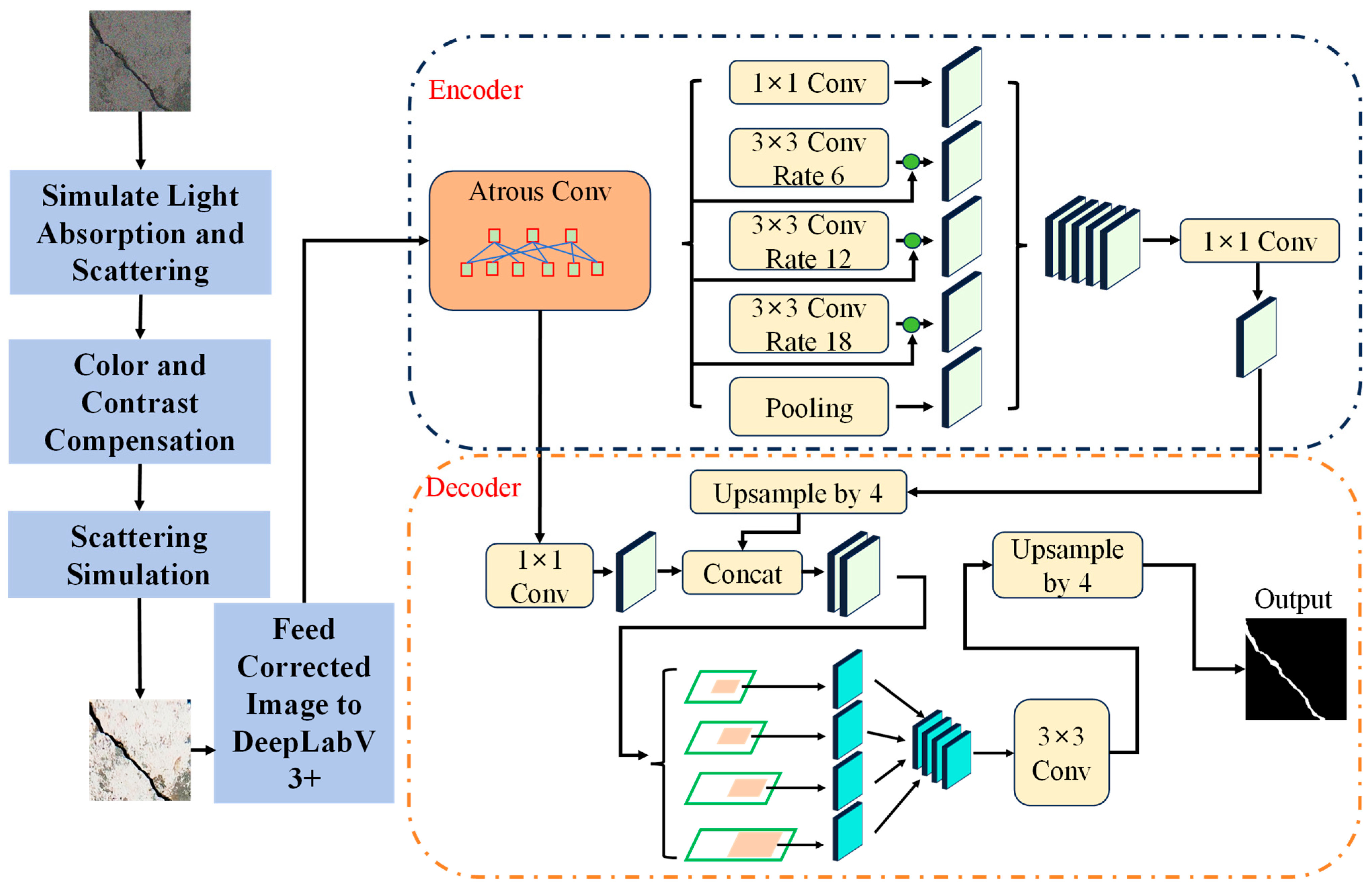
2. Methods
2.1. DeepLabV3+ Architecture and Training Framework
2.2. Innovation 1: Underwater Light Propagation Model
2.2.1. Principle of Underwater Light Propagation Model
2.2.2. Model Mechanics and Compensation Approach
2.2.3. Preprocessing Pipeline
- (1)
- Simulate Light Absorption and Scattering: The model simulates the underwater light propagation using the formulas for absorption and scattering.
- (2)
- Color and Contrast Compensation: Based on depth and the light absorption model, the image is corrected for color loss and contrast reduction.
- (3)
- Scattering Simulation: The effects of light scattering are simulated and compensated for, improving clarity.
- (4)
- Feed Corrected Image to DeepLabV3+: The preprocessed image is then passed to the DeepLabV3+ model, providing a cleaner, more balanced input for crack detection.
2.2.4. Theoretical Impact on Segmentation
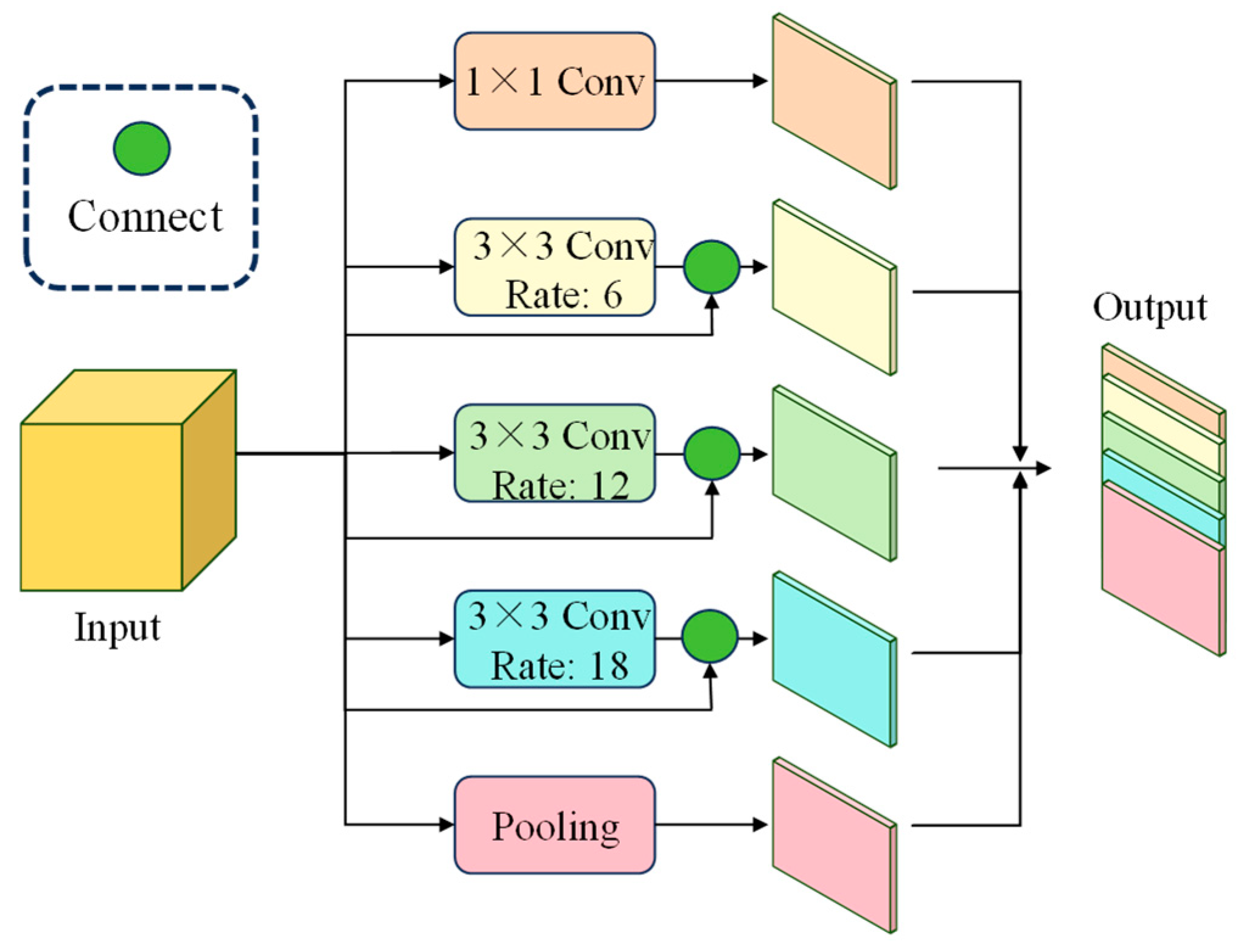
2.3. Innovation 2: Multi-Scale Feature Extraction
2.4. Innovation 3: Curvature Flow-Based Guidance
2.4.1. Curvature Flow and Its Role in Crack Detection
2.4.2. Curvature Flow-Based Guidance Integration
2.4.3. Curvature Flow Regularization
2.4.4. Final Loss Function
2.4.5. Theoretical Guarantees
2.5. Unified Performance Analysis
3. Experimental Setup
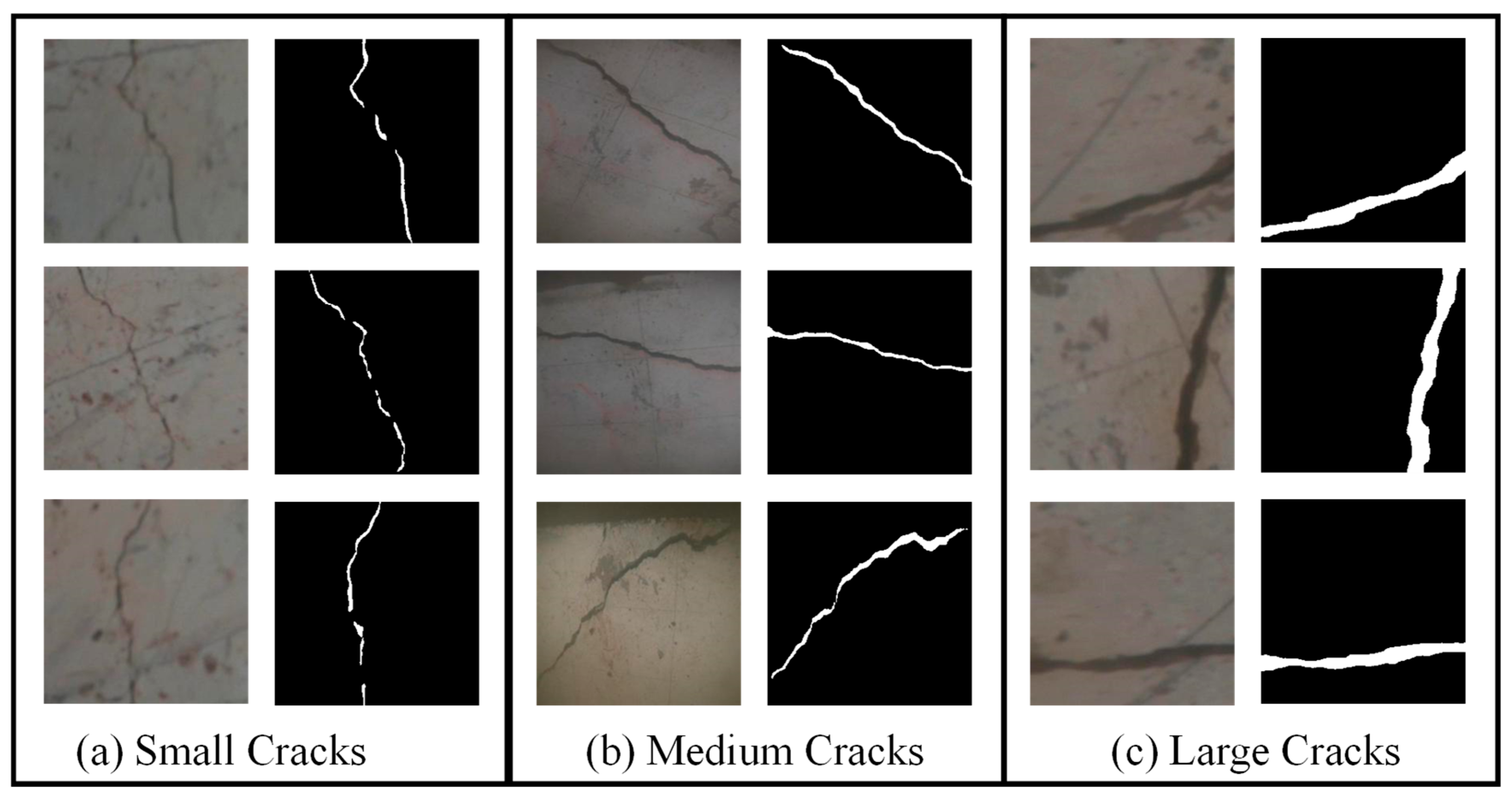
3.1. Dataset
3.2. Evaluation Metrics
3.3. Implementation Details
4. Results
4.1. Quantitative Results
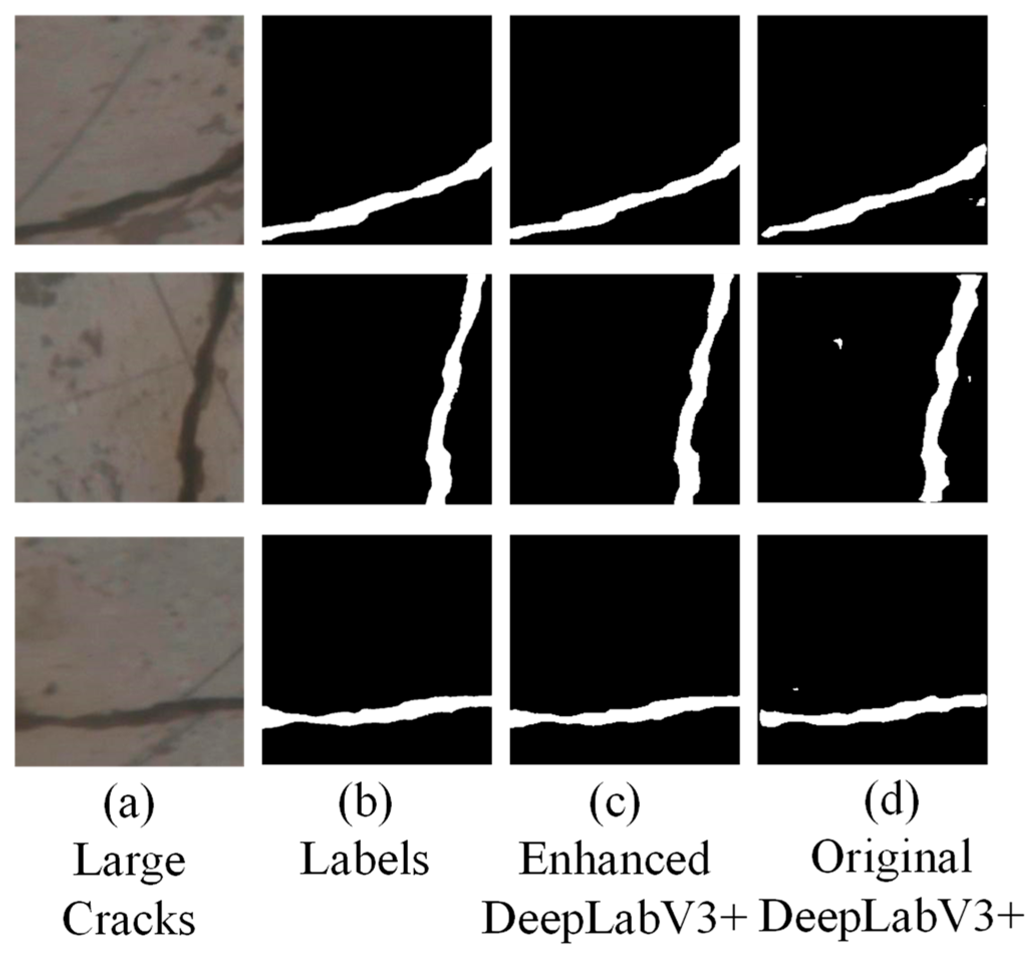
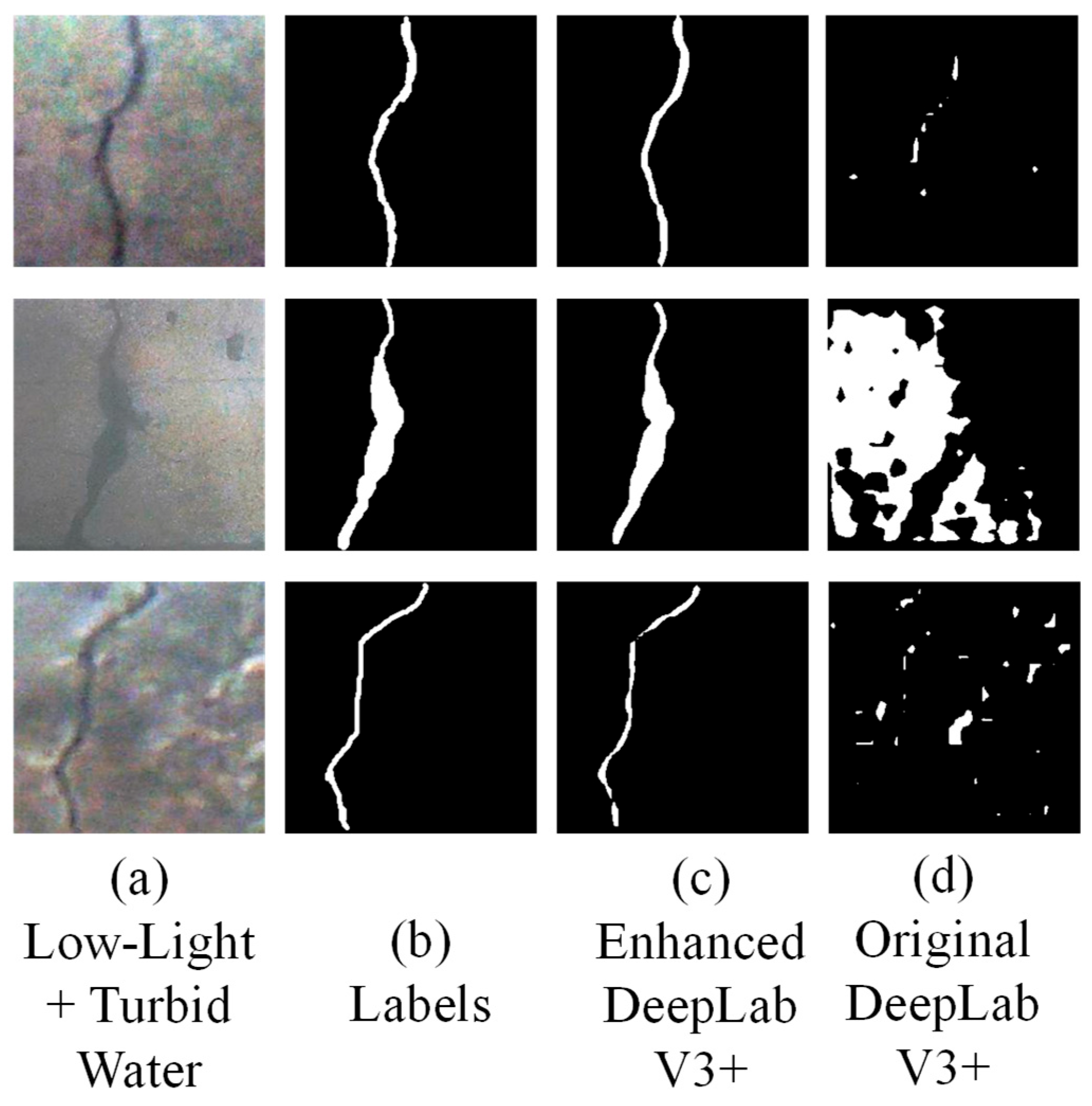
4.2. Qualitative Results
4.3. Computational Efficiency
4.4. Impact of Dataset Scaling
5. Discussion
6. Conclusions
- A total of 82.5% IoU and 79.8% Crack Detection Accuracy, outperforming DeepLabV3+ by 10.6% IoU.
- A total of 78.1% small crack IoU for sub-0.5 mm defects, resolving prior scale limitations.
- Less than 9% performance degradation under low-light or high-turbidity conditions (>12 NTU).
Author Contributions
Funding
Data Availability Statement
Conflicts of Interest
References
- Yuan, X.; Li, W.; Chen, G.; Yin, X.; Li, X.; Liu, J.; Zhao, J.; Zhao, J. Visual and Intelligent Identification Methods for Defects in Underwater Structure Using Alternating Current Field Measurement Technique. IEEE Trans. Ind. Inform. 2022, 18, 3853–3862. [Google Scholar] [CrossRef]
- Yang, Y.; Hirose, S.; Debenest, P.; Guarnieri, M.; Izumi, N.; Suzumori, K. Development of a stable localized visual inspection system for underwater structures. Adv. Robot. 2016, 30, 1415–1429. [Google Scholar] [CrossRef]
- Cao, W.; Li, J. Detecting large-scale underwater cracks based on remote operated vehicle and graph convolutional neural network. Front. Struct. Civ. Eng. 2022, 16, 1378–1396. [Google Scholar] [CrossRef]
- Bi, Q.; Lai, M.; Yu, J.; Tang, Z.; Teng, X.; Lu, Y.; Zou, J. Method for detecting surface defects of underwater buildings: Binocular vision based on sinusoidal grating fringe assistance. Alex. Eng. J. 2023, 78, 120–130. [Google Scholar] [CrossRef]
- Bao, L.; Zhao, C.; Xue, X.; Yu, L. Improved Dark Channel Defogging Algorithm for Defect Detection in Underwater Structures. Adv. Mater. Sci. Eng. 2020, 2020, 8760324. [Google Scholar] [CrossRef]
- Edalati, K.; Edalati, A.; Kermani, A. Thickness Gaging of Thin Plates by Multi-Peak Frequency Decomposition of Lamb Wave Signals. J. Test. Eval. 2008, 36, 264–272. [Google Scholar] [CrossRef]
- Edalati, K.; Kermani, A.; Seiedi, M.; Movafeghi, A. Defect detection in thin plates by ultrasonic lamb wave techniques. Int. J. Mater. Prod. Technol. 2006, 27, 156–172. [Google Scholar] [CrossRef]
- Muravyov, S.V.; Nguyen, D.C. Method of interval fusion with preference aggregation in brightness thresholds selection for automatic weld surface defects recognition. Measurement 2024, 236, 114969. [Google Scholar] [CrossRef]
- Muravyov, S.V.; Nguyen, D.C. Automatic Segmentation by the Method of Interval Fusion with Preference Aggregation When Recognizing Weld Defects. Russ. J. Nondestruct. Test. 2023, 59, 1280–1290. [Google Scholar] [CrossRef]
- Xu, S.; Zhang, M.; Song, W.; Mei, H.; He, Q.; Liotta, A. A systematic review and analysis of deep learning-based underwater object detection. Neurocomputing 2023, 527, 204–232. [Google Scholar] [CrossRef]
- Shi, P.; Fan, X.; Ni, J.; Wang, G. A detection and classification approach for underwater dam cracks. Struct. Health Monit. 2016, 15, 551–564. [Google Scholar] [CrossRef]
- Ma, Y.P.; Wu, Y.; Li, Q.W.; Zhou, Y.Q.; Yu, D.B. ROV-based binocular vision system for underwater structure crack detection and width measurement. Multimed. Tools Appl. 2023, 82, 20899–20923. [Google Scholar] [CrossRef]
- Jinchao, W.; Houcheng, L.; Yongan, S.; Feng, W.; Baoliang, W. Damage identification of railway bridge underwater foundations based on optical images. Urban Clim. 2023, 51, 101662. [Google Scholar] [CrossRef]
- Talaei Khoei, T.; Ould Slimane, H.; Kaabouch, N. Deep learning: Systematic review, models, challenges, and research directions. Neural Comput. Appl. 2023, 35, 23103–23124. [Google Scholar] [CrossRef]
- Zhu, S.S.; Li, X.Y.; Wan, G.; Wang, H.R.; Shao, S.; Shi, P.F. Underwater Dam Crack Image Classification Algorithm Based on Improved VanillaNet. Symmetry 2024, 16, 845. [Google Scholar] [CrossRef]
- Li, X.; Sun, H.; Song, T.; Zhang, T.; Meng, Q. A method of underwater bridge structure damage detection method based on a lightweight deep convolutional network. IET Image Process. 2022, 16, 3893–3909. [Google Scholar] [CrossRef]
- Talib, L.F.; Amin, J.; Sharif, M.; Raza, M. Transformer-based semantic segmentation and CNN network for detection of histopathological lung cancer. Biomed. Signal Process. Control 2024, 92, 106106. [Google Scholar] [CrossRef]
- Dong, Q.; Chen, X.; Jiang, L.; Wang, L.; Chen, J.; Zhao, Y. Semantic Segmentation of Remote Sensing Images Depicting Environmental Hazards in High-Speed Rail Network Based on Large-Model Pre-Classification. Sensors 2024, 24, 1876. [Google Scholar] [CrossRef] [PubMed]
- Hou, S.T.; Shen, H.; Wu, T.; Sun, W.H.; Wu, G.; Wu, Z.S. Underwater Surface Defect Recognition of Bridges Based on Fusion of Semantic Segmentation and Three-Dimensional Point Cloud. J. Bridge Eng. 2025, 30, 04024101. [Google Scholar] [CrossRef]
- Sun, W.H.; Hou, S.T.; Wu, G.; Zhang, Y.J.; Zhao, L.C. Two-step rapid inspection of underwater concrete bridge structures combining sonar, camera, and deep learning. Comput.-Aided Civ. Infrastruct. Eng. 2024, 40, 2650–2670. [Google Scholar] [CrossRef]
- Giglioni, V.; Poole, J.; Mills, R.; Venanzi, I.; Ubertini, F.; Worden, K. Transfer learning in bridge monitoring: Laboratory study on domain adaptation for population-based SHM of multispan continuous girder bridges. Mech. Syst. Signal Process. 2025, 224, 112151. [Google Scholar] [CrossRef]
- Liu, F.; Ding, W.; Qiao, Y.; Wang, L. Transfer learning-based encoder-decoder model with visual explanations for infrastructure crack segmentation: New open database and comprehensive evaluation. Undergr. Space 2024, 17, 60–81. [Google Scholar] [CrossRef]
- Li, Y.T.; Bao, T.F.; Huang, X.J.; Chen, H.; Xu, B.; Shu, X.S.; Zhou, Y.H.; Cao, Q.B.; Tu, J.Z.; Wang, R.J.; et al. Underwater crack pixel-wise identification and quantification for dams via lightweight semantic segmentation and transfer learning. Autom. Constr. 2022, 144, 104600. [Google Scholar] [CrossRef]
- Teng, S.; Liu, A.R.; Situ, Z.; Chen, B.C.; Wu, Z.H.; Zhang, Y.X.; Wang, J.L. Plug-and-play method for segmenting concrete bridge cracks using the segment anything model with a fractal dimension matrix prompt. Autom. Constr. 2025, 170, 105906. [Google Scholar] [CrossRef]
- Xu, Z.; Wu, D.; Yu, C.; Chu, X.; Sang, N.; Gao, C. SCTNet: Single-Branch CNN with Transformer Semantic Information for Real-Time Segmentation. In Proceedings of the AAAI Conference on Artificial Intelligence, Vancouver, BC, Canada, 20–27 February 2024. [Google Scholar]
- Yu, H.; Dai, D.; Zhao, Z.; He, D.; Hu, H.; Wang, L. LarvSeg: Exploring Image Classification Data for Large Vocabulary Semantic Segmentation via Category-Wise Attentive Classifier. In Proceedings of the Chinese Conference on Pattern Recognition and Computer Vision (PRCV), Singapore, 18–20 October 2024; pp. 50–64. [Google Scholar]
- Bai, Y.; Li, J.; Shi, L.; Jiang, Q.; Yan, B.; Wang, Z. DME-DeepLabV3+: A lightweight model for diabetic macular edema extraction based on DeepLabV3+ architecture. Front. Med. 2023, 10, 1150295. [Google Scholar] [CrossRef] [PubMed]
- Fang, H. Semantic Segmentation of PHT Based on Improved DeeplabV3+. Math. Probl. Eng. 2022, 2022, 6228532. [Google Scholar] [CrossRef]
- Chen, L.-C.; Zhu, Y.; Papandreou, G.; Schroff, F.; Adam, H. Encoder-Decoder with Atrous Separable Convolution for Semantic Image Segmentation. In Proceedings of the European Conference on Computer Vision (ECCV), Munich, Germany, 8–14 September 2018; pp. 833–851. [Google Scholar]
- Sandler, M.; Howard, A.; Zhu, M.; Zhmoginov, A.; Chen, L.C. MobileNetV2: Inverted Residuals and Linear Bottlenecks. In Proceedings of the 2018 IEEE/CVF Conference on Computer Vision and Pattern Recognition, Salt Lake City, UT, USA, 18–23 June 2018; pp. 4510–4520. [Google Scholar]
- Zhao, X.; Jin, T.; Qu, S. Deriving inherent optical properties from background color and underwater image enhancement. Ocean Eng. 2015, 94, 163–172. [Google Scholar] [CrossRef]
- Gonzalez, R.; Woods, R. Digital Image Processing; Pearson Education: New York, NY, USA, 2018. [Google Scholar]
- Chen, L.; Ren, Z.; Ma, C.; Chen, G. Modeling and simulating the bidirectional reflectance distribution function (BRDF) of seawater polluted by oil emulsion. Optik 2017, 140, 878–886. [Google Scholar] [CrossRef]
- Zhao, C.; Lv, W.; Zhang, X.; Yu, Z.; Wang, S. MMS-Net: Multi-level multi-scale feature extraction network for medical image segmentation. Biomed. Signal Process. Control 2023, 86, 105330. [Google Scholar] [CrossRef]
- Imiya, A.; Saito, M.; Tatara, K.; Nakamura, K. Digital Curvature Flow and Its Application for Skeletonization. J. Math. Imaging Vis. 2003, 18, 55–68. [Google Scholar] [CrossRef]
- Koike, N.; Yamamoto, H. Gauss maps of the Ricci-mean curvature flow. Geom. Dedicata 2018, 194, 169–185. [Google Scholar] [CrossRef]
- Situ, Z.; Teng, S.; Feng, W.; Zhong, Q.; Chen, G.; Su, J.; Zhou, Q. A transfer learning-based YOLO network for sewer defect detection in comparison to classic object detection methods. Dev. Built Environ. 2023, 15, 100191. [Google Scholar] [CrossRef]
- Iraniparast, M.; Ranjbar, S.; Rahai, M.; Moghadas Nejad, F. Surface concrete cracks detection and segmentation using transfer learning and multi-resolution image processing. Structures 2023, 54, 386–398. [Google Scholar] [CrossRef]
- Chen, B.; Zhang, H.; Wang, G.; Huo, J.; Li, Y.; Li, L. Automatic concrete infrastructure crack semantic segmentation using deep learning. Autom. Constr. 2023, 152, 104950. [Google Scholar] [CrossRef]


| Model | IoU (%) | p-Value | F1 Score (%) | p-Value | Pixel Accuracy (%) | Crack Detection Accuracy (%) |
|---|---|---|---|---|---|---|
| Original DeepLabV3+ | 71.9 | <0.001 | 76.8 | <0.001 | 83.6 | 68.7 |
| DeepLabV3+ with Light Model | 76.3 | 0.003 | 80.8 | 0.002 | 87.6 | 73.1 |
| Enhanced DeepLabV3+ (Proposed) | 82.5 | 0.008 | 85.6 | 0.009 | 90.3 | 79.8 |
| SCTNet (2024) | 70.4 | <0.001 | 76.1 | <0.001 | 81.6 | 66.1 |
| LarvSeg (2025) | 69.1 | <0.001 | 74.3 | <0.001 | 80.7 | 63.9 |
| Mask2Former (2021) | 75.1 | 0.002 | 80.2 | 0.002 | 85.6 | 72.4 |
| Swin-UNet (2021) | 76.8 | 0.003 | 81.5 | 0.003 | 86.9 | 74.2 |
| Crack Size | Original DeepLabV3+ IoU (%) | DeepLabV3+ with Light Model IoU (%) | Enhanced DeepLabV3+ IoU (%) |
|---|---|---|---|
| Small Cracks | 65.6 | 70.8 | 78.1 |
| Medium Cracks | 74.5 | 78.3 | 85.2 |
| Large Cracks | 80.8 | 83.3 | 89.2 |
| Water Condition | Original DeepLabV3+ IoU (%) | Enhanced DeepLabV3+ IoU (%) | Degradation (%) |
|---|---|---|---|
| Clear Water | 71.9 | 82.5 | |
| Mildly Turbid | 67.4 | 78.9 | −3.6 |
| Highly Turbid | 61.5 | 73.7 | −8.8 |
| Low Light | 64.1 | 76.2 | −6.3 |
| Model Variant | Inference Time (ms) | FPS | Hardware |
|---|---|---|---|
| Original DeepLabV3+ | 12.5 | 80.0 | RTX 4090, 24 GB VRAM |
| Enhanced DeepLabV3+ (Ours) | 14.7 | 68.0 | RTX 4090, 24 GB VRAM |
| SCTNet (2024) | 18.3 | 54.6 | RTX 4090, 24 GB VRAM |
| LarvSeg (2025) | 21.6 | 46.3 | RTX 4090, 24 GB VRAM |
| Mask2Former (2021) | 19.8 | 53.1 | RTX 4090, 24 GB VRAM |
| Swin-UNet (2021) | 15.9 | 70.8 | RTX 4090, 24 GB VRAM |
| Metric | 450 Images | 1037 Images | |
|---|---|---|---|
| Overall IoU (%) | 74.3 | 82.5 | +8.2 |
| Small Crack IoU (%) | 69.9 | 78.1 | +8.2 |
| Crack Det. Acc (%) | 70.7 | 79.8 | +9.1 |
| IoU Std. Dev. (Turbidity) | 4.8 | 4.2 | −12.3% |
Disclaimer/Publisher’s Note: The statements, opinions and data contained in all publications are solely those of the individual author(s) and contributor(s) and not of MDPI and/or the editor(s). MDPI and/or the editor(s) disclaim responsibility for any injury to people or property resulting from any ideas, methods, instructions or products referred to in the content. |
© 2025 by the authors. Licensee MDPI, Basel, Switzerland. This article is an open access article distributed under the terms and conditions of the Creative Commons Attribution (CC BY) license (https://creativecommons.org/licenses/by/4.0/).
Share and Cite
Ai, W.; Zou, J.; Liu, Z.; Wang, S.; Teng, S. Light Propagation and Multi-Scale Enhanced DeepLabV3+ for Underwater Crack Detection. Algorithms 2025, 18, 462. https://doi.org/10.3390/a18080462
Ai W, Zou J, Liu Z, Wang S, Teng S. Light Propagation and Multi-Scale Enhanced DeepLabV3+ for Underwater Crack Detection. Algorithms. 2025; 18(8):462. https://doi.org/10.3390/a18080462
Chicago/Turabian StyleAi, Wenji, Jiaxuan Zou, Zongchao Liu, Shaodi Wang, and Shuai Teng. 2025. "Light Propagation and Multi-Scale Enhanced DeepLabV3+ for Underwater Crack Detection" Algorithms 18, no. 8: 462. https://doi.org/10.3390/a18080462
APA StyleAi, W., Zou, J., Liu, Z., Wang, S., & Teng, S. (2025). Light Propagation and Multi-Scale Enhanced DeepLabV3+ for Underwater Crack Detection. Algorithms, 18(8), 462. https://doi.org/10.3390/a18080462