
Macro-Encapsulated PCM Cylinder Module Based on Paraffin and Float Stones

Abstract
:1. Introduction
2. Experimental
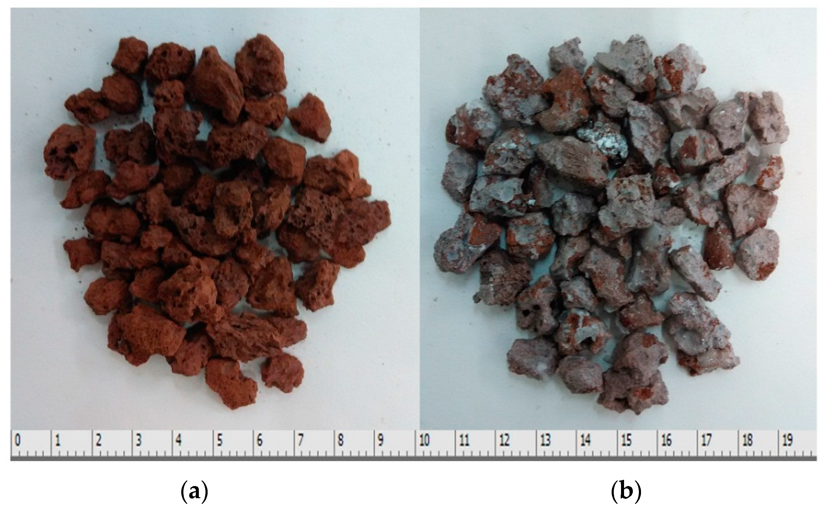
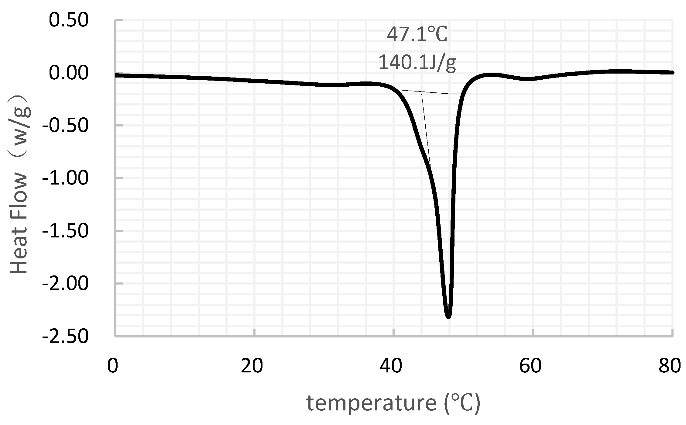
2.1. The Used PCM
2.2. Improvement of the Comprehensive Thermal Conductivity
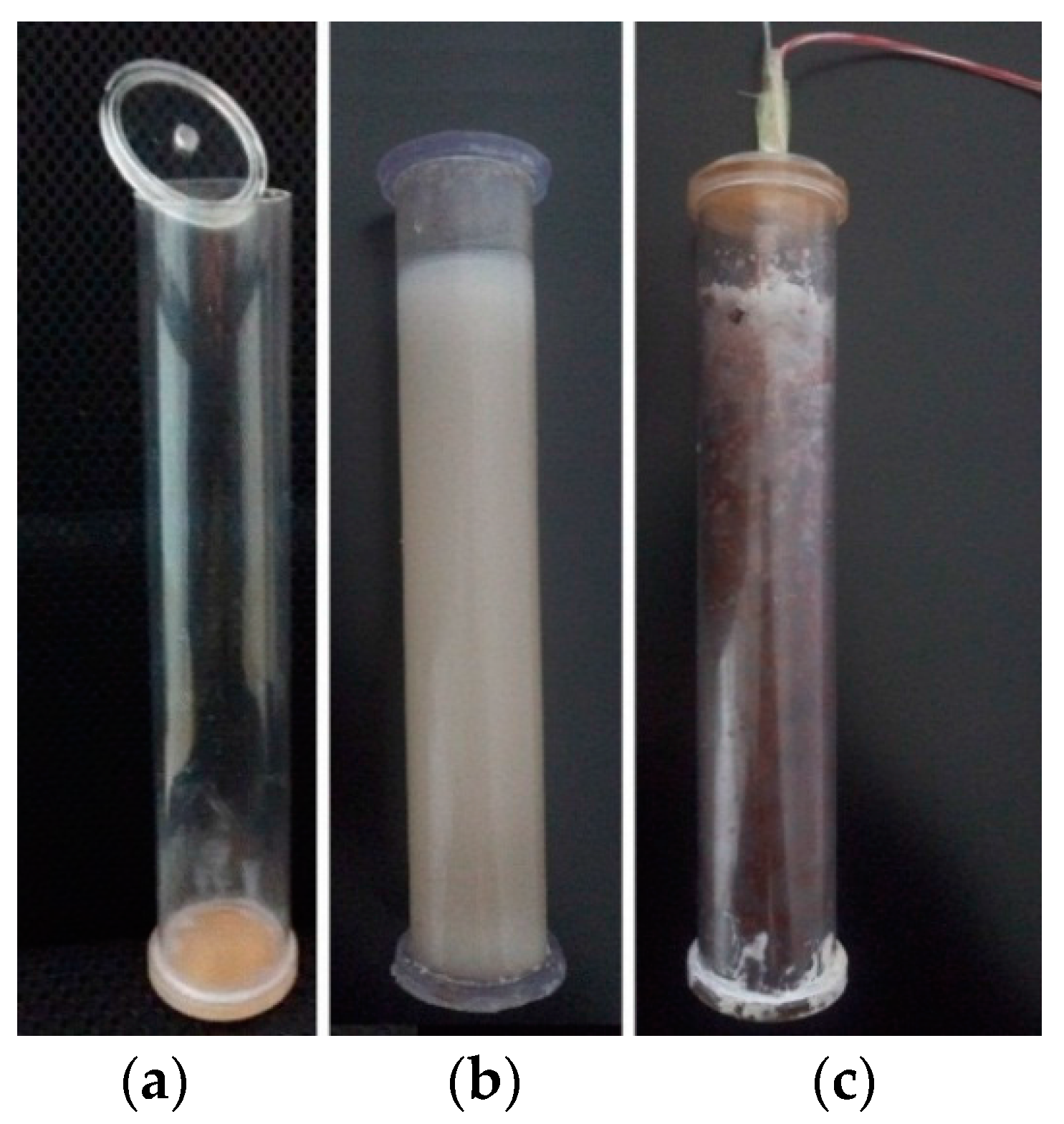
2.3. Preparation of the PCM Cylinder Module
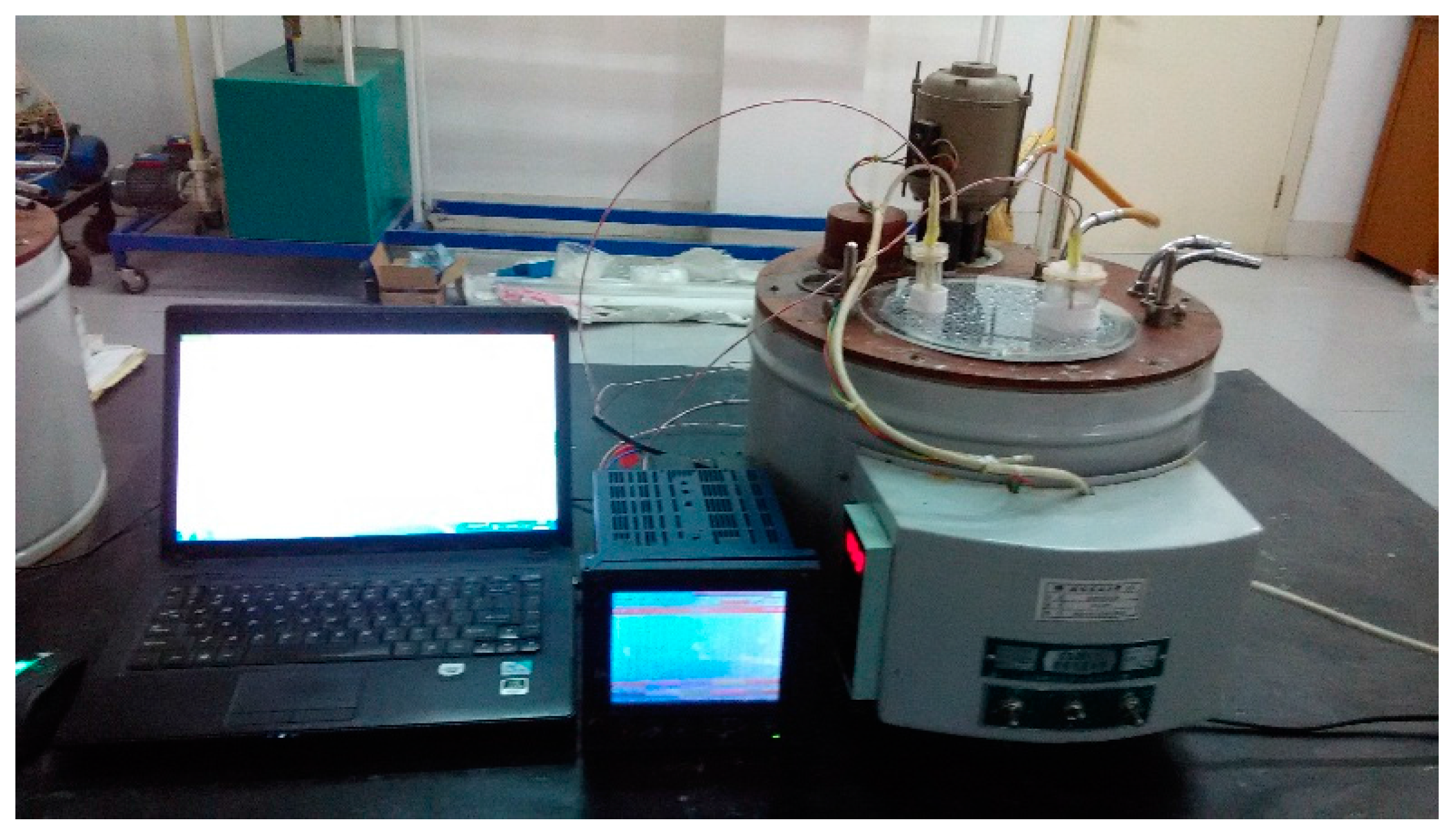
2.4. Test Arrangement
3. Numerical Simulations
3.1. Governing Equations
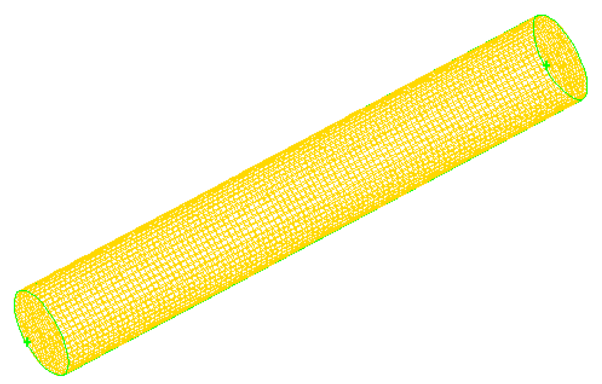
3.2. Model in the CFD Software
3.3. Boundary and Initial Conditions
4. Results and Discussion
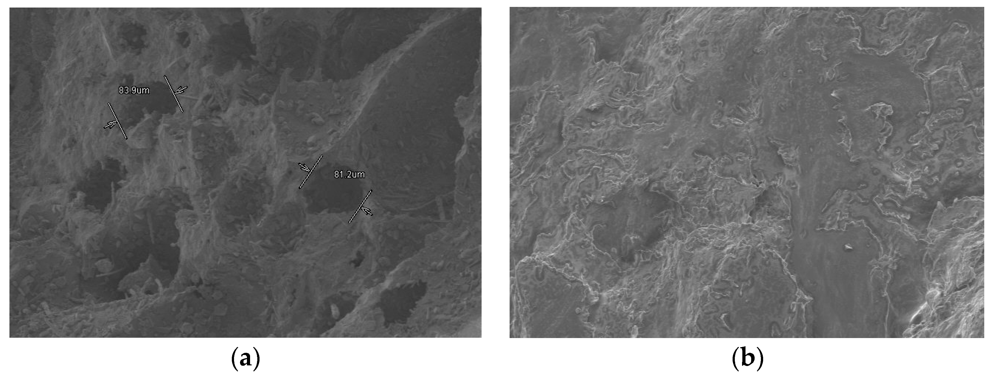
4.1. Microstructure Analyses and Leakage Analysis
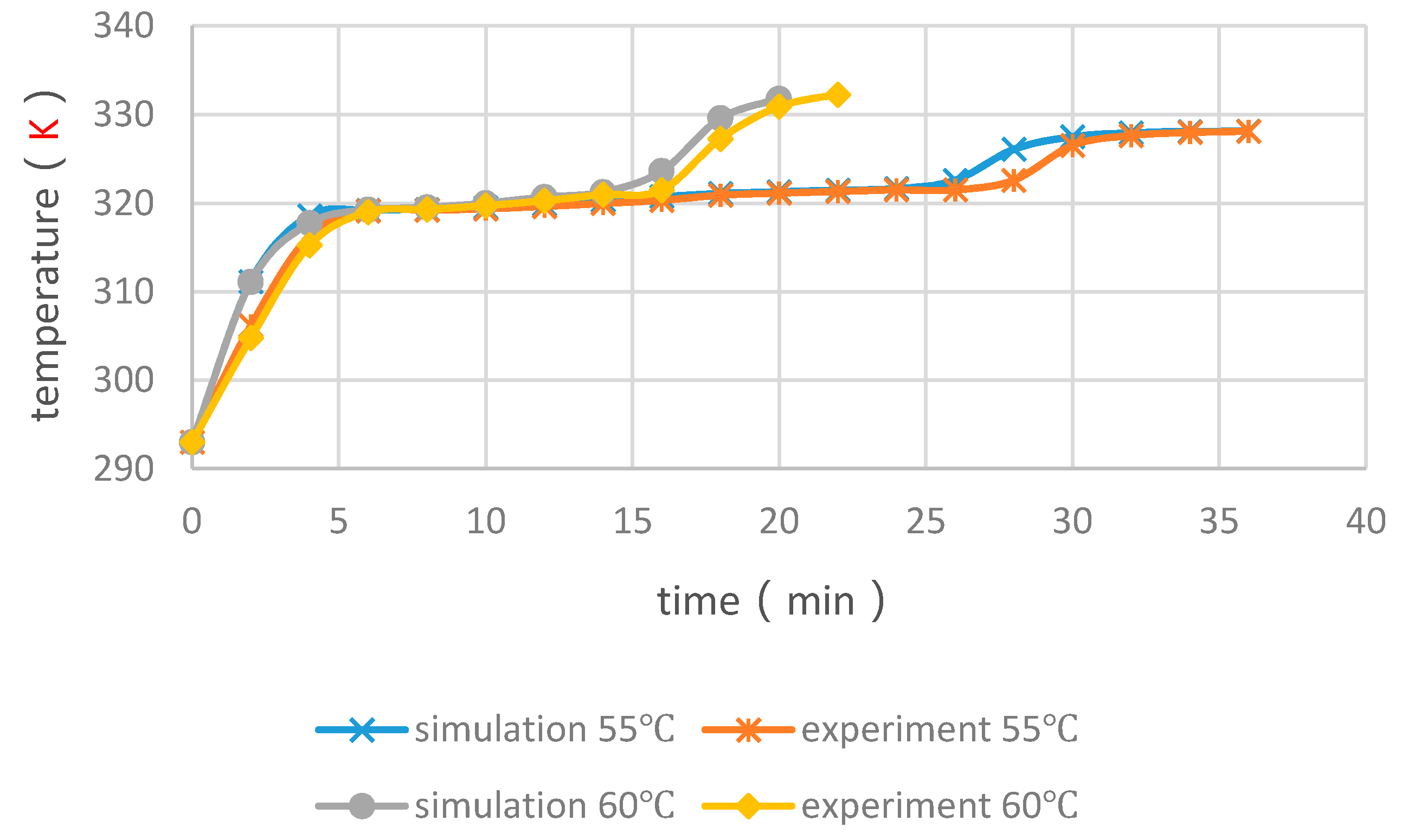
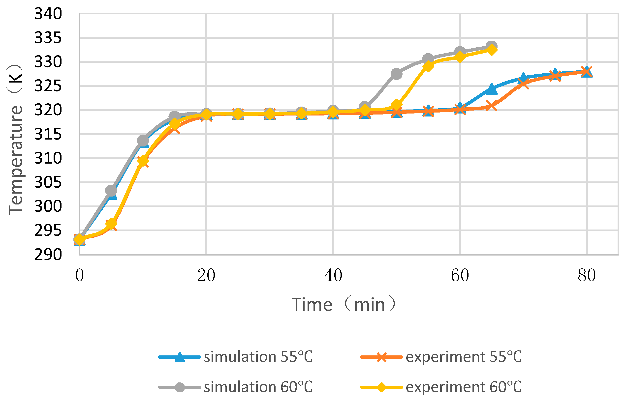
4.2. Validation of the Simulation
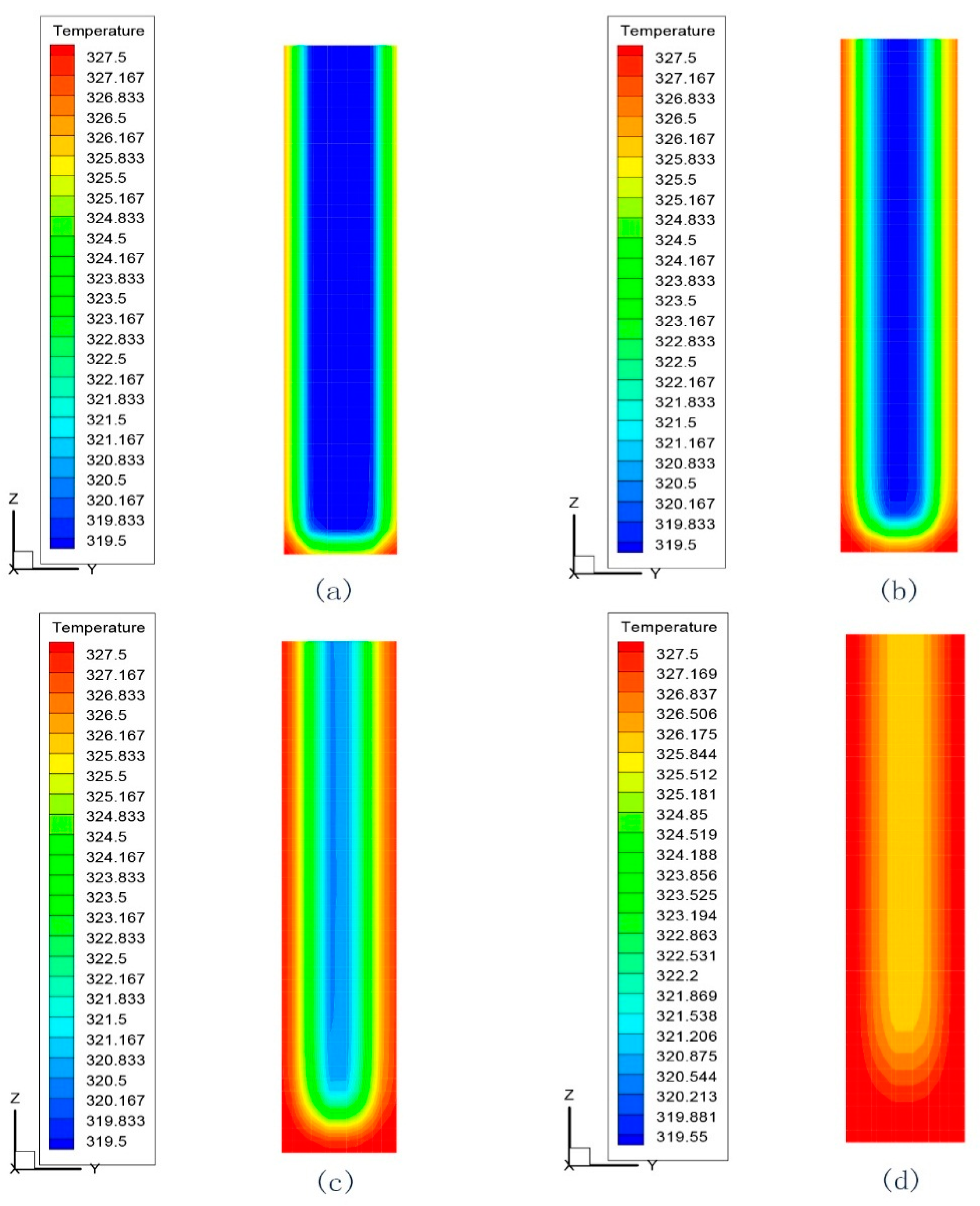
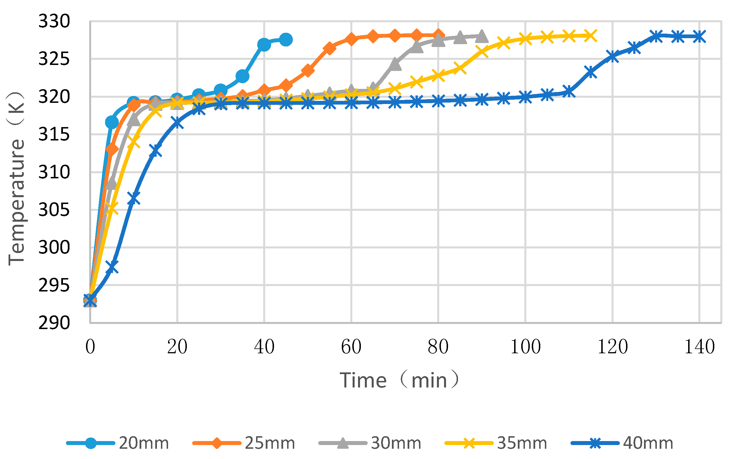
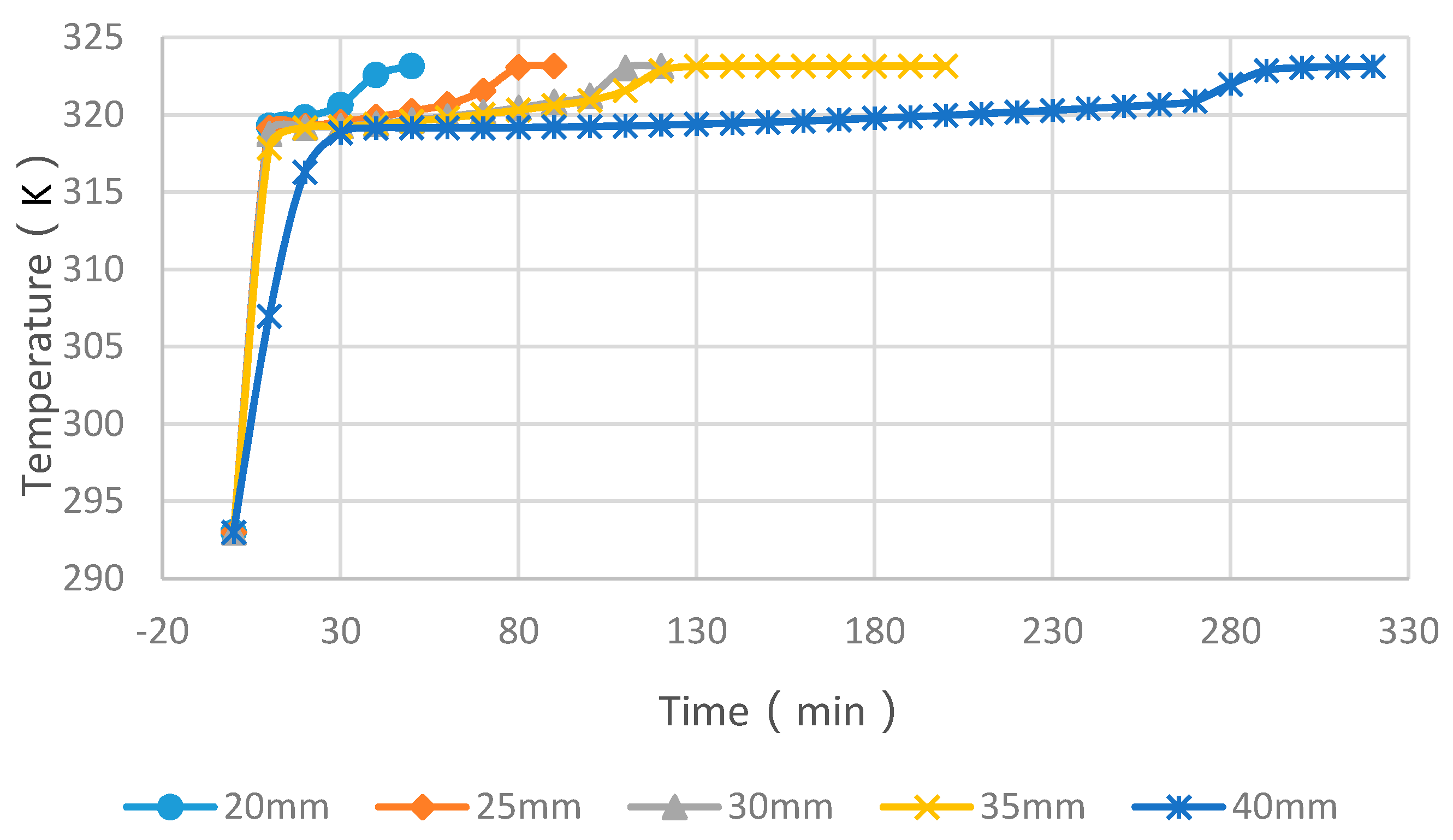
4.3. Simulation Cases of Different Cylinder Diameters with Float Stones
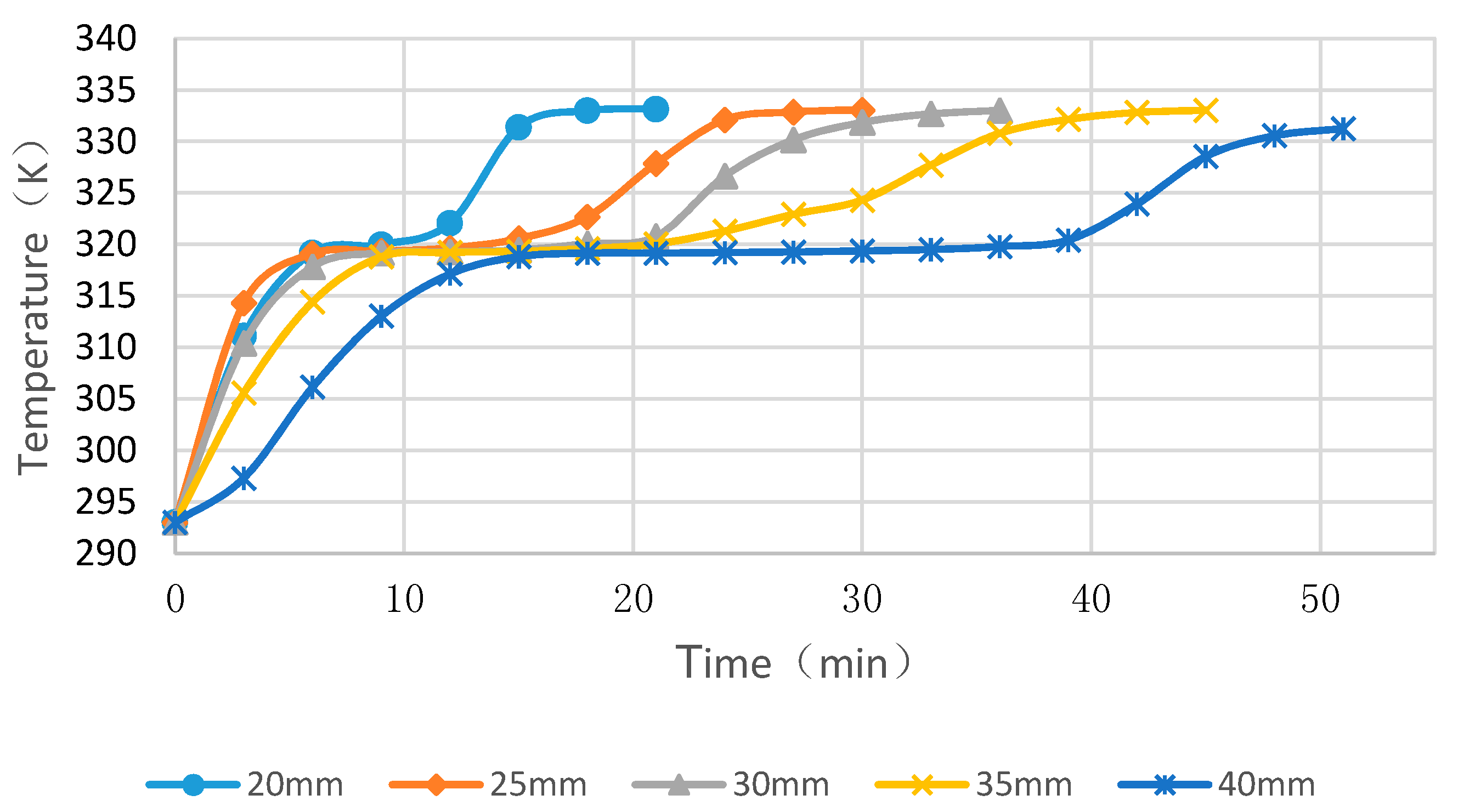
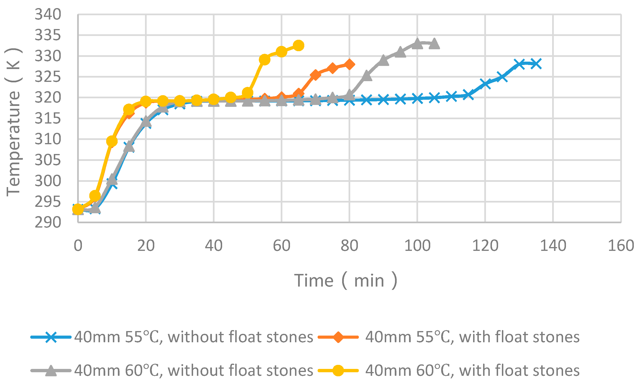
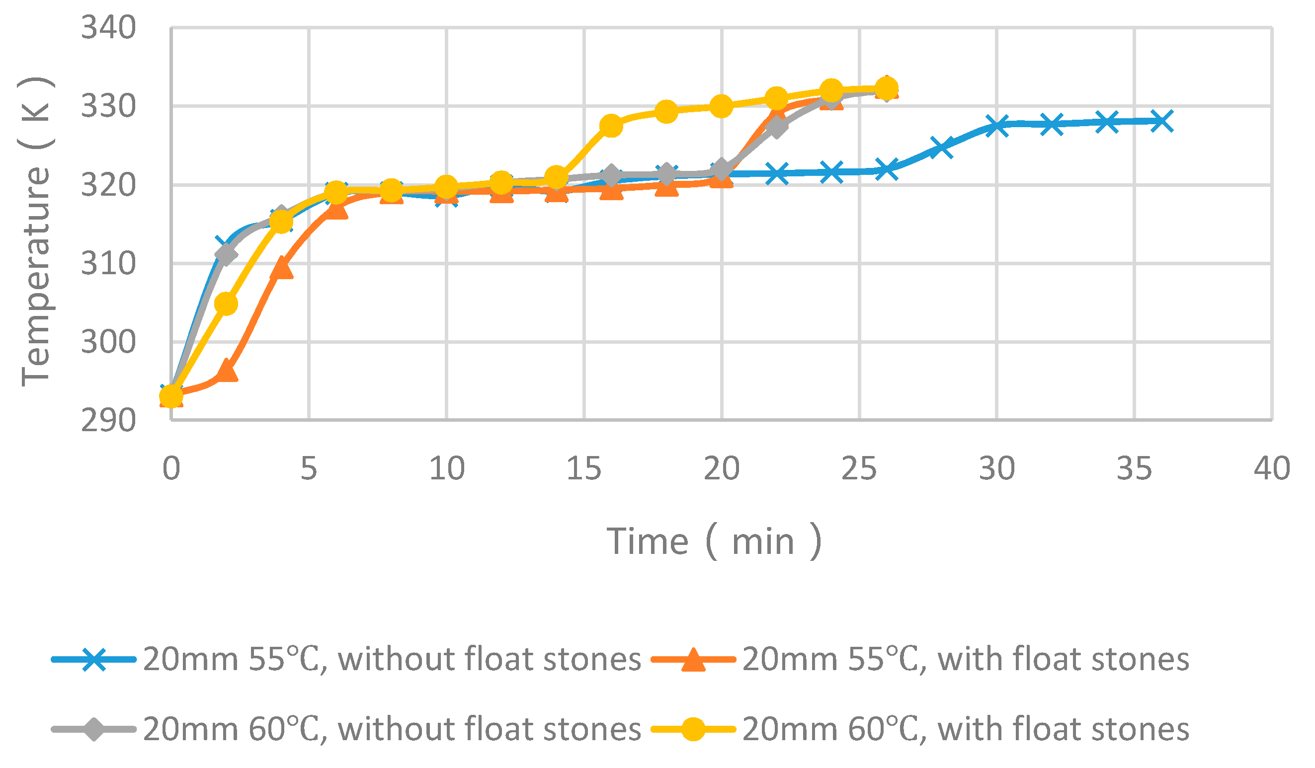
4.4. Experimental Cases with and without Float Stones
5. Conclusions
Acknowledgments
Author Contributions
Conflicts of Interest
References
- Sharma, R.K.; Ganesan, P.; Tyagi, V.V.; Metselaar, H.S.C.; Sandaran, S.C. Developments in organic solid-liquid phase change materials and their applications in thermal energy storage. Energy Convers. Manag. 2015, 95, 193–228. [Google Scholar] [CrossRef]
- Agyenim, F.; Hewitt, N.; Eames, P.; Smyth, M. A review of materials, heat transfer and phase change problem formulation for latent heat thermal energy storage systems (LHTESS). Renew. Sustain. Energy Rev. 2010, 14, 615–628. [Google Scholar] [CrossRef]
- Pasupathy, A.; Velraj, R.; Seeniraj, R.V. Phase change material-based building architecture for thermal management in residential and commercial establishments. Renew. Sustain. Energy Rev. 2008, 12, 39–64. [Google Scholar] [CrossRef]
- Zhou, D.; Zhao, C.Y.; Tian, Y. Review on thermal energy storage with phase change materials (PCMs) in building applications. Appl. Energy 2012, 92, 593–605. [Google Scholar] [CrossRef]
- Sharma, A.; Tyagi, V.V.; Chen, C.R.; Buddhi, D. Review on thermal energy storage with phase change materials and applications. Renew. Sustain. Energy Rev. 2009, 13, 318–345. [Google Scholar] [CrossRef]
- Kenisarin, M.; Mahkamov, K. Solar energy storage using phase change materials. Renew. Sustain. Energy Rev. 2007, 11, 1913–1965. [Google Scholar] [CrossRef]
- Fan, L.; Khodadadi, J.M. Thermal conductivity enhancement of phase change materials for thermal energy storage: A review. Renew. Sustain. Energy Rev. 2011, 15, 24–46. [Google Scholar] [CrossRef]
- Ermis, K.; Erek, A.; Dincer, I. Heat transfer analysis of phase change process in a finned-tube thermal energy storage system using artificial neural network. Int. J. Heat Mass Transf. 2007, 50, 3163–3175. [Google Scholar] [CrossRef]
- Ismail, K.A.R.; Alves, C.L.F.; Modesto, M.S. Numerical and experimental study on the solidification of PCM around a vertical axially finned isothermal cylinder. Appl. Therm. Eng. 2001, 21, 53–77. [Google Scholar] [CrossRef]
- Velraj, R.; Seeniraj, R.V.; Hafner, B.; Faber, C.; Schwarzer, K. Experimental analysis and numerical modeling of inward solidification on a finned vertical tube for a latent heat storage unit. Solar Energy 1997, 60, 281–290. [Google Scholar] [CrossRef]
- Trelles, J.P.; Dufly, J.J. Numerical simulation of porous latent heat thermal energy storage for thermoelectric cooling. Appl. Therm. Eng. 2003, 23, 1647–1664. [Google Scholar] [CrossRef]
- Hoogendoorn, C.J.; Bart, G.C.J. Performance and modelling of latent heat stores. Sol. Energy 1992, 48, 53–58. [Google Scholar] [CrossRef]
- Mettawee, E.S.; Assassa, G.M.R. Thermal conductivity enhancement in a latent heat storage system. Sol. Energy 2007, 81, 839–845. [Google Scholar] [CrossRef]
- Babaei, H.; Keblinski, P.; Khodadadi, J.M. Thermal conductivity enhancement of paraffins by increasing the alignment of molecules through adding CNT/graphene. Int. J. Heat Mass Transf. 2013, 58, 209–216. [Google Scholar] [CrossRef]
- Babaei, H.; Keblinski, P.; Khodadadi, J.M. Improvement in thermal conductivity of paraffin by adding high aspect-ratio carbon-based nano-fillers. Phys. Lett. A 2013, 377, 1358–1361. [Google Scholar] [CrossRef]
- Hawlader, M.N.A.; Uddin, M.S.; Khin, M.M. Microencapsulated PCM thermal energy storage system. Appl. Energy 2003, 74, 195–202. [Google Scholar] [CrossRef]
- Agyenim, F.; Eames, P.; Smyth, M. Heat transfer enhancement in medium temperature thermal energy storage system using a multitube heat transfer array. Renew. Energy 2010, 35, 198–207. [Google Scholar] [CrossRef]
- Hendra, R.; Hamdani; Mahlia, T.M.I.; Masjuki, H.H. Thermal and melting heat transfer characteristics in a latent heat storage system using mikro. Appl. Therm. Eng. 2005, 25, 1503–1515. [Google Scholar] [CrossRef]
- Radhakrishnan, R.; Gubbins, K.E. Free energy studies of freezing in slit pores: An order-parameter approach using Monte Carlo simulation. Mol. Phys. 1999, 96, 1249–1267. [Google Scholar] [CrossRef]
- Carreto, L.; Almeida, A.R.; Fernandes, A.C.; Vaz, W.L.C. Thermotropic mesomor-phism of a model system for the plant epicuticular wax layer. Biophys. J. 2002, 82, 530–540. [Google Scholar] [CrossRef]
- De Gracia, A.; Oró, E.; Farid, M.M.; Cabeza, L.F. Thermal analysis of including phase change material in a domestic hot water cylinder. Appl. Therm. Eng. 2011, 31, 3938–3945. [Google Scholar] [CrossRef]
- Mazman, M.; Cabeza, L.F.; Mehling, H.; Nogues, M.; Evliya, H.; Paksoy, H.O. Utilization of phase change materials in solar domestic hot water systems. Renew. Energy 2009, 34, 1639–1643. [Google Scholar] [CrossRef]
- Alishaev, M.G.; Abdulagatov, I.M.; Abdulagatova, Z.Z. Effective thermal conductivity of fluid-saturated rocks Experiment and modeling. Eng. Geol. 2012, 135–136, 24–39. [Google Scholar] [CrossRef]
- Ozkahraman, H.T.; Selver, R.; Isık, E.C. Determination of the thermal conductivity of rock from P-wave velocity. Int. J. Rock Mech. Min. Sci. 2004, 41, 703–708. [Google Scholar] [CrossRef]
- Song, S.; Liao, Q.; Shen, W. Effective thermal conductivity of composites filled with different shape particles. J. Chongqing Univ. 2011, 34, 87–91. [Google Scholar]
- Guo, S.; Li, H.; Zhao, J.; Li, X.; Yan, J. Numerical simulation study on optimizing charging process of the direct contact mobilized thermal energy storage. Appl. Energy 2013, 112, 1416–1423. [Google Scholar] [CrossRef]


| Constituent | SiO2 | CaO | MgO | Fe2O3 | FeO | Al2O3 | TiO2 | K2O | Na2O |
|---|---|---|---|---|---|---|---|---|---|
| Ratio (%) | 53.82 | 8.36 | 2.46 | 9.08 | 1.12 | 16.89 | 0.06 | 2.30 | 2.55 |
| Number | Hot Water Temperature | Module Diameter | Remarks |
|---|---|---|---|
| Number 1 | 55 °C | 20 mm | Each case include PCM cylinder modules with and without float stones. |
| Number 2 | 60 °C | 20 mm | |
| Number 3 | 55 °C | 40 mm | |
| Number 4 | 60 °C | 40 mm |
© 2016 by the authors; licensee MDPI, Basel, Switzerland. This article is an open access article distributed under the terms and conditions of the Creative Commons Attribution (CC-BY) license (http://creativecommons.org/licenses/by/4.0/).
Share and Cite
Huang, K.; Liang, D.; Feng, G.; Jiang, M.; Zhu, Y.; Liu, X.; Jiang, B. Macro-Encapsulated PCM Cylinder Module Based on Paraffin and Float Stones. Materials 2016, 9, 361. https://doi.org/10.3390/ma9050361
Huang K, Liang D, Feng G, Jiang M, Zhu Y, Liu X, Jiang B. Macro-Encapsulated PCM Cylinder Module Based on Paraffin and Float Stones. Materials. 2016; 9(5):361. https://doi.org/10.3390/ma9050361
Chicago/Turabian StyleHuang, Kailiang, Dong Liang, Guohui Feng, Mingzhi Jiang, Yuhua Zhu, Xin Liu, and Bian Jiang. 2016. "Macro-Encapsulated PCM Cylinder Module Based on Paraffin and Float Stones" Materials 9, no. 5: 361. https://doi.org/10.3390/ma9050361
APA StyleHuang, K., Liang, D., Feng, G., Jiang, M., Zhu, Y., Liu, X., & Jiang, B. (2016). Macro-Encapsulated PCM Cylinder Module Based on Paraffin and Float Stones. Materials, 9(5), 361. https://doi.org/10.3390/ma9050361