1. Introduction
Engine fan blades and discs are subjected to extreme temperatures and mechanical stresses during their operation. The prediction of damage initiation and propagation is important in these engine components, not only to avoid potential catastrophic mission failures, but for developing optimal and economical designs as well. Developing such prediction capabilities requires development of stress analysis models that can incorporate the interaction of various microstructural features, such as grain boundaries and dislocations.
For metals and metallic alloys, the major deformation mechanism at the microstructural scale is the dislocation motion causing plasticity. Two key characteristics that define plasticity are the permanent strain due to slipping of atomic layers under shear stress and the strain hardening, both contributing to the macroscale nonlinear stress-strain behavior. In the single crystal plasticity models, the dislocation motion is implemented as permanent shear strain in the various slip systems (slip plane and slip direction) with the aid of a set of state variables [
1,
2]. The strain hardening property that defines the strength of the slip systems is also implemented in terms of another set of state variables. The nonlinear evolution laws are defined for the permanent shear strains and strength of slip systems, along with the equilibrium equations in an incremental and iterative approach.
The major challenge in implementing microstructure-based plasticity models in real-sized structural components is the excessive computational cost, as it requires solving governing equations at both the microstructural and macrostructural length scales. Even for modeling a small subscale volume consisting of tens to a few hundred grains, the computational cost for executing a finite element model incorporating the physics of dislocation at the microscale motion is exorbitant. To address this challenge, the development of various multiscale models, broadly classified under three major methods, namely, sequential (or hierarchical), computational homogenization scheme (so called
) and integrated technique, were reported [
3,
4,
5,
6].
In the sequential method, the macro model utilizes a number of parameters which are either obtained from a detailed microscale experimental analysis or pre-computed [
7,
8,
9,
10,
11,
12,
13]. As a result, these models are effectively macroscopic models, but use internal state variables for describing the material behavior at microscale. Therefore, sequential methods are valid for prediction and computationally very efficient. However, the macroscale models are typically calibrated using a finite number of loading scenarios and do not account for the material’s microstructure explicitly. Thus, sequential methods may lack some fidelity in capturing the anisotropic constitutive response of a polycrystal under completely general loading scenarios.
The computational homogenization scheme, on the other hand, can relate the complex material behavior at microscale to its macroscale response by explicitly modeling the material’s microstructure [
6,
14,
15,
16,
17,
18,
19,
20,
21,
22]. In these methods, the local governing behavior at the macroscale is determined by solving the microscale boundary value problem on a representative volume element. This also affords the use of simpler, more fundamental constitutive models at the microscale, since the anisotropic nonlinearity at the macroscale arises naturally due to the interaction of the various phases at the microscale. This micro-macro transition can also be implemented by considering coupled boundary value problems at the micro- and macroscales, and solving them simultaneously by means of finite element methods. The computational homogenization scheme, though offering high fidelity, can still be computationally expensive for many practical problems.
The integrated method is based on applying a homogenization technique to an embedded polycrystal in a finite element framework. The homogenization technique, mostly mean-field theories, serves as the transition step between the micro and macro scales [
5,
23,
24,
25,
26,
27]. The microstructure is discretized and split into different phases with analytical relations describing the interaction between the phases. While providing relatively good accuracy, depending on the mean-field theory used, these methods are computationally very efficient. Recent studies have demonstrated successful implementation of a viscoplastic self-consistent model for composite materials, both under explicit [
23,
24,
26] and implicit schemes [
25].
A main challenge in the development of a homogenization technique is relating the macroscale average strain at a point to the microstructural representation of the material. The homogenization technique is formulated following two major methods: (1) The Representative Volume Element (RVE) method based on statistical homogenization theories considering the random distribution of the microstructural features; and (2) The Repeating Unit Cells (RUC) method based on periodicity in the microstructure. The definition of RVE requires the equivalent homogenized displacement and traction boundary conditions to be simultaneously satisfied. The RUC-based methods were proposed to address the difficulty in satisfying the required homogenous traction–displacement boundary condition for arbitrarily chosen, statistically homogeneous, microstructures in the RVE concept. Besides analytical methods, those mainly developed for elastic materials, the numerical solutions of the RUC using boundary element method [
28], the discrete Fourier transform approach [
29,
30] and the finite element method [
31], have been developed for inelastic, viscoelastic and viscoplastic materials. These RUC-based homogenization techniques are mostly restricted to specific unit-cell architecture, loading direction and simplified boundary condition.
Semi-analytical techniques such as the generalized method of cells (GMC) have also been developed for RUC homogenization [
32,
33,
34,
35]. The GMC method enables modeling of complex unit-cell architectures and is capable of studying the elastic–plastic response of periodic heterogeneous materials under various loading conditions. In GMC, an RUC is discretized into a number of sub-volumes, referred to as subcells. Within each of these subcells, the displacement fields are approximated linearly. Traction and displacement continuity conditions are utilized to calculate a strain concentration matrix allowing localization of the applied, average, far-field strains to local subcell strains. The GMC method does not include coupling between the shear and normal components of stress. Many micromechanics theories exhibit this lack of coupling, which typically yields ultra-efficient computational performance. However, retaining this coupling is only critical when this coupling is a first-order effect. Advanced methods [
33,
34,
36,
37], such as the High-Fidelity Generalized Method of Cells (HFGMC) were proposed to account for the shear coupling through quadratic displacement approximations in the subcells. However, increase in fidelity incurs a penalty on the computational efficiency.
In this article, GMC is evaluated as a potential method of homogenization to develop a multiscale model that can capture microscale plastic deformation in polycrystal metals and metallic alloys. This work is an extension of a previous study by authors [
38,
39] on the applicability of GMC homogenization for studying two-phase materials, e.g., Ni-base superalloys, characterized by crystal plasticity framework at microstructures. Polycrystalline materials, with several randomly oriented grains, demonstrate high material anisotropy; this anisotropy introduces its own challenges and is the focus for this study. At first, the performance of the stand-alone GMC for simple test cases, in terms of solution accuracy and computational time, is evaluated by comparing the results with a finite element model that uses the same material subroutine. The polycrystal microstructure is simulated using a pre-processor functionality that creates Voronoi cell tessellations and assigns random orientations. A small polycrystal sample with 8, 27 and 125 grains is then simulated using stand-alone GMC compared with the FEA model. Finally, the multiscale model implemented on a finite element analysis framework at macroscale, with the element properties defined at microscale using GMC homogenization, is evaluated by analyzing a realistic engine disc component.
3. Results and Discussion
The main objective for a multiscale analysis is to provide an accurate constitutive response to the higher scale, being the average stress and strain behaviors of the microscale. In addition, for a failure study of a structure, it is helpful to be able to predict the field quantities at a microstructural length scale. In the results and discussion section of this study it has been attempted to evaluate the GMC homogenized solution combined with the crystal plasticity framework in polycrystalline materials with regard to both the entire RUC and the local microstructural behaviors.
In order to evaluate GMC for studying the plasticity in polycrystals, several virtual test cases, under a tensile stress of 200 with a constant loading rate of 200 applied in z direction, were considered. In the FEA model, periodic boundary conditions were applied in all three directions to simulate the periodicity of the unit cell in a bulk domain. At first, the stress–strain behaviors of a single crystal sample under uniaxial loading was analyzed and compared with FEA. This was followed by a polycrystalline sample made up of two grains. Both the global stress–strain curves obtained from the entire domain and the local stress-strain curves of the individual grains were compared. Then, the analyses of polycrystals with 27, 64 and 125 grains were implemented. A face-centered-cubic (FCC) copper sample with 12 active slip systems ({111} <110> family) and the cubic material properties () are used in this study. For the hardening law, and were applied. In addition, the rate sensitivity exponent , reference strain rate . and the ratio of latent to self-hardening moduli . were taken as 10 and 0.001 and 1, respectively, for the present study.
The polycrystal grain structure was simulated using the Voronoi tessellations and the grain orientations were randomly assigned using MATLAB built-in functions. The GMC uses a linear displacement approximation in each subcell, and as a result of the lack of normal-shear coupling, as long as the geometry of the phases in the RUC is fixed, the solution of GMC is completely insensitive to refinement of the subcell grid. More discussions on the mesh sensitivity in GMC are available in [
33]. However, for similar element-wise resolution in the polycrystalline samples in both the FEA and GMC, to obtain a proper solution in FEA 20-node-brick elements were required.
Finally, the capability of GMC homogenization to solve large-scale problems was demonstrated by using the FEAMAC multiscale model framework. A 254 mm radius turbine disk was analyzed using FEA at the macroscale. At each element integration point, an RUC representing a microstrcuture consisting of 27 grain polycrystal material is used to model the local non-linear material repsonse. The homogenization at the element level is carried out by GMC with 1000 subcells.
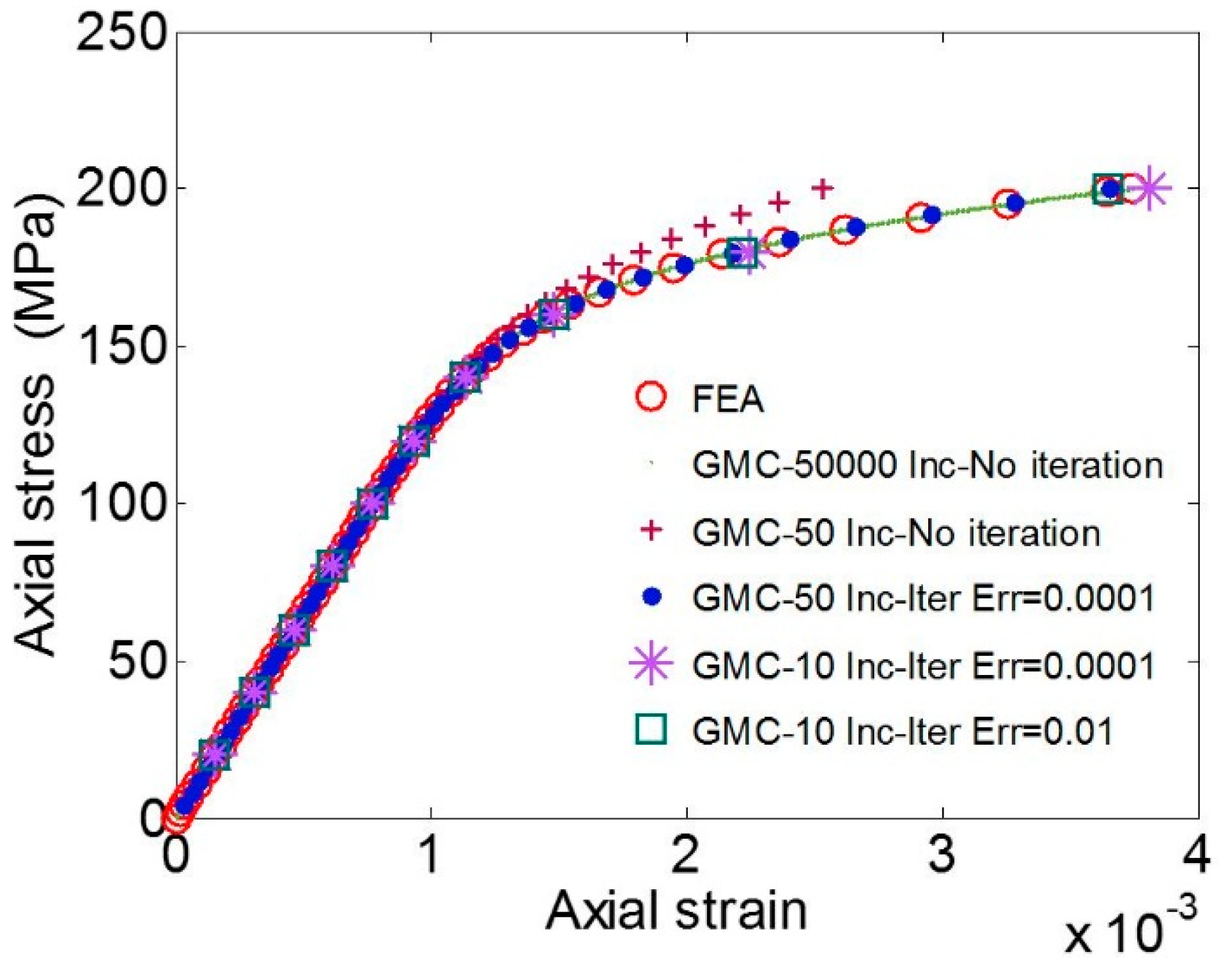
3.1. Single Crystal Behavior
A 100 × 10 × 10
single crystal copper sample, with (1,1,0) crystal orientation modeled by 90 subcells/elements under a uniaxial tensile loading in the sample length direction (
z direction), was considered. The corresponding results in terms of the variation of average axial stress (
σzz)
vs. the average axial strain (
εzz) are shown in
Figure 2.
The GMC convergence was studied by varying time increments, number of iterations and permitted error (ERR) for the convergence. It is observed that the GMC solution can converge to the solution from FEA, either by refining the load increments without changing the number of iterations, or, for the smaller number of load increments, by allowing for more iterations.
3.2. Polycrystal Behavior
Applicability of the GMC base homogenization approach for polycrystalline samples are studied in this section. At first, in
Section 3.2.1, a polycrystalline sample consisting of two grains with maximum possible anisotropy with respect to the grain orientations is analyzed. Then, Voronoi polycrystals with several numbers of grains with randomly oriented grains, representing real material microstructures, are studied in
Section 3.2.2.
3.2.1. Two-Grain Polycrystal
A simple polycrystal consisting of two grains, as shown in
Figure 3, is considered. The orientations chosen for the grains are shown in
Table 1. The arbitrarily chosen orientation provides a high degree of anisotropy in the studied sample.
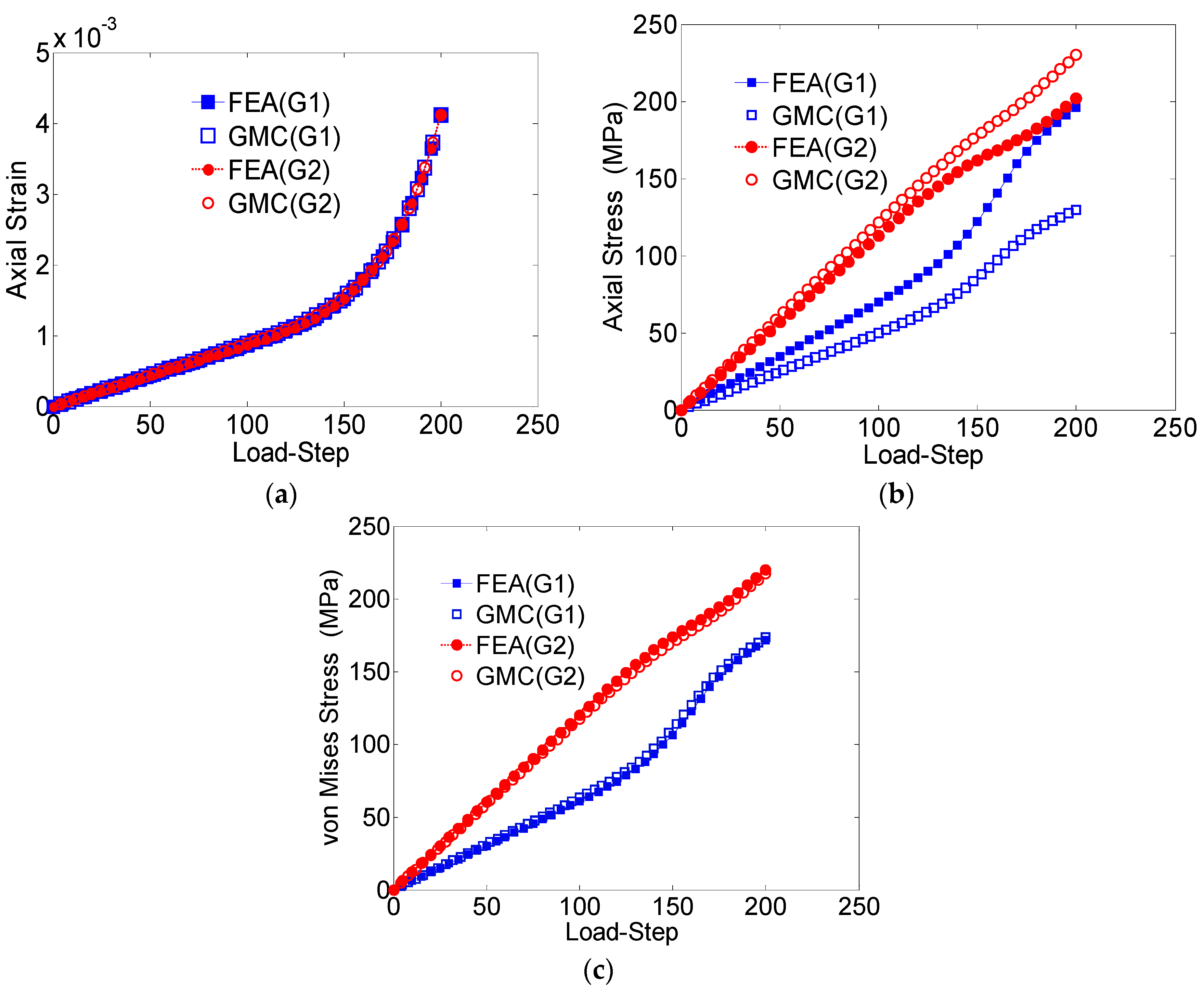
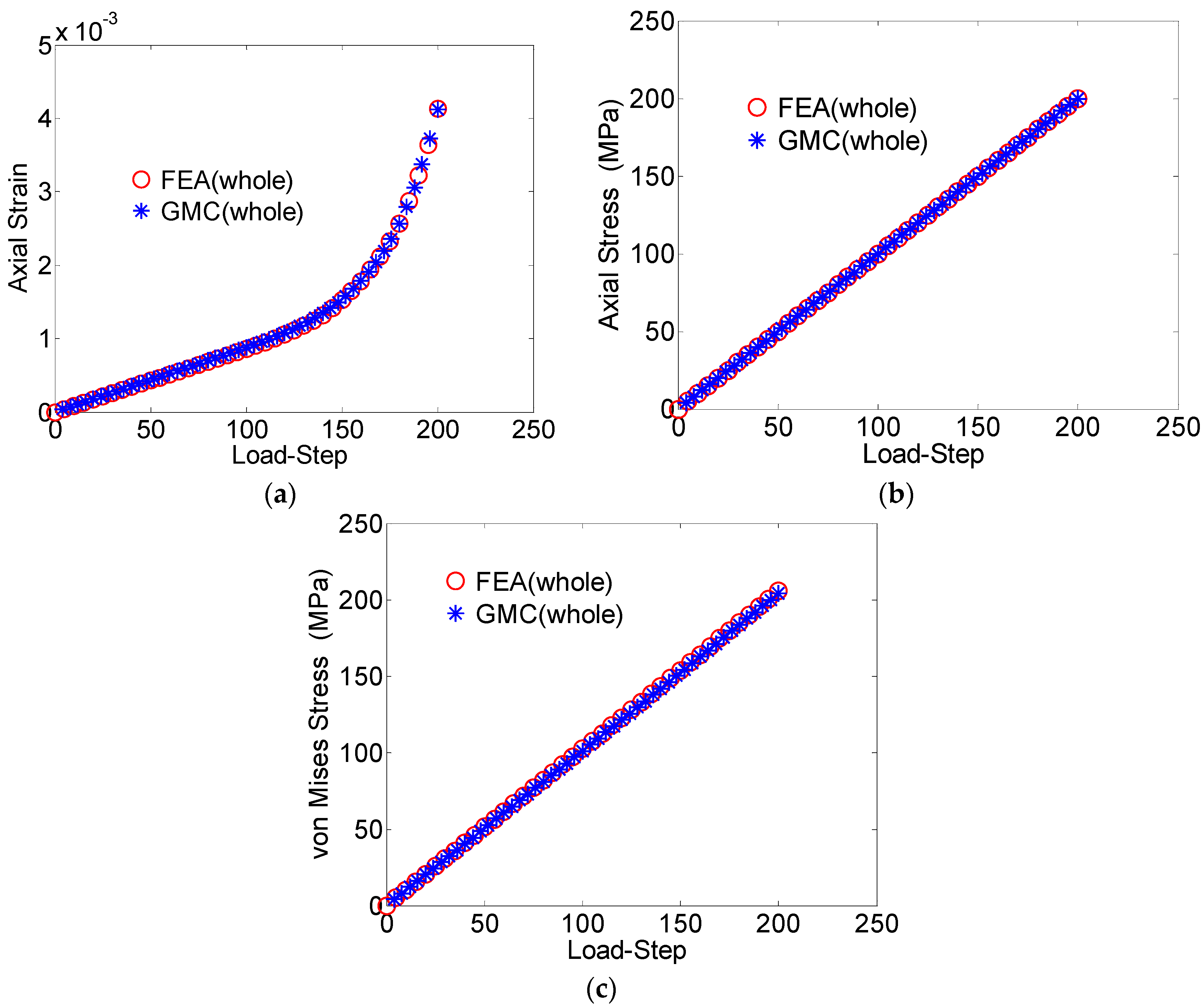
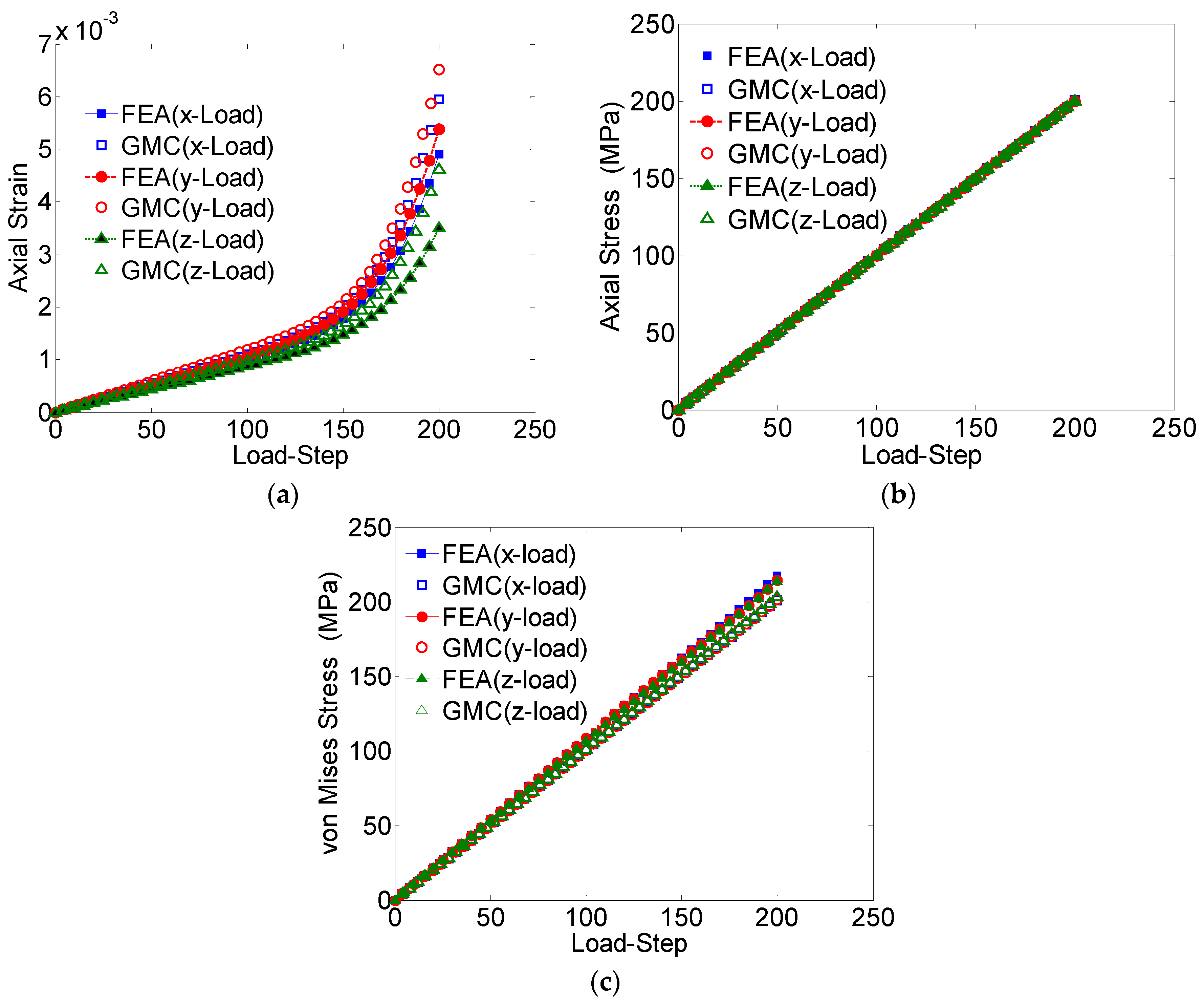
The average axial strain component (
εzz), the average axial stress component (
σzz) and the average von Mises stress plotted against the load-step for the entire domain are shown in
Figure 4a–c, respectively. The average values of the studied field quantities were calculated by taking the volume-weighted average over all the elements. With regards to the average RUC behavior, the GMC results show excellent agreement with the FEA solutions.
The local microstructural response of the RUC is also studied in
Figure 5 by comparing the GMC
vs. FEA results with regard to the average element-wise behaviors corresponding to each of the grains for the applied stress load. For the axial stress
vs. the load step (
Figure 5b), some discrepancy between the reported results from GMC and FEA for each individual grain is observed. The difference is significant in the elastic regime, which contributes to the difference in the overall behavior. On the contrary, the average von Mises stress behavior (
Figure 5c), which is a measure of the shear deformation, and the average axial strain (
Figure 5a) demonstrates good agreement in both the elastic and plastic zones.
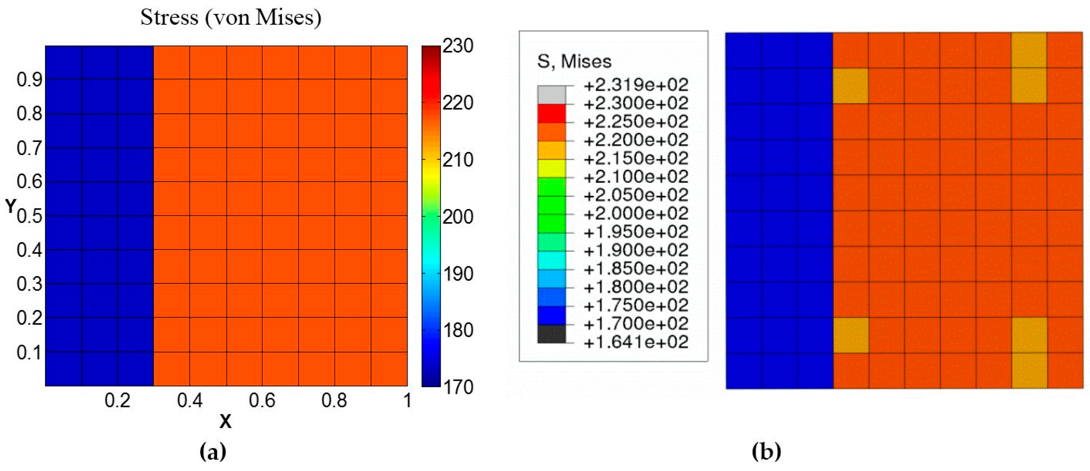
Table 2 reports the maximum error percentile for each of these cases. Similarly, the von Mises stress distribution at a cross-section taken midway through the length in the loading direction for the strain loading case also matches in each grain (
Figure 6).
Therefore, it can be concluded from these results that GMC could be quite effective for homogenization in terms of predicting the effective stress quantities, such as von Mises, while the prediction of individual components of stress tensor could be below satisfactory due to homogenization and lack of shear coupling.
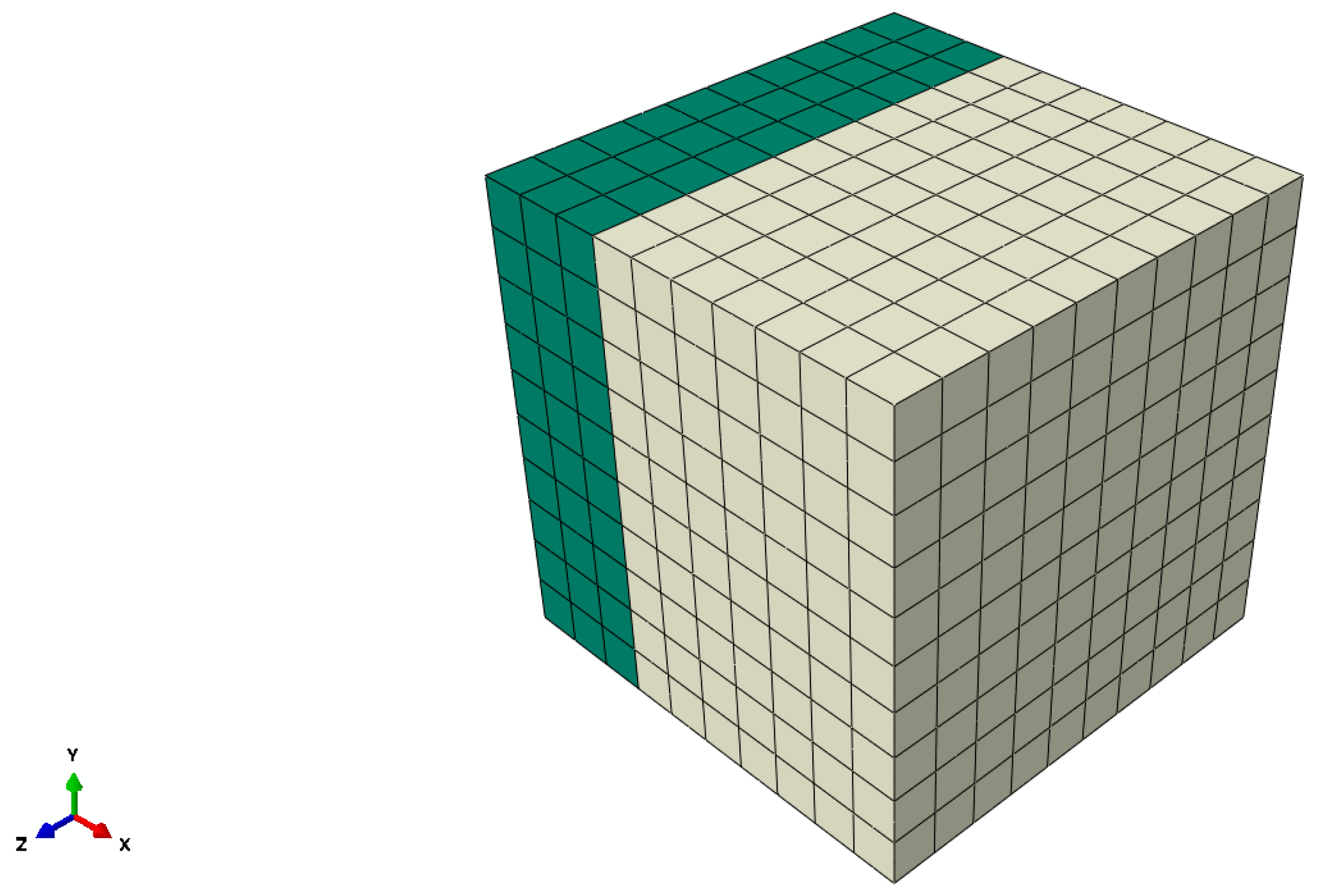
3.2.2. Voronoi Polycrystal
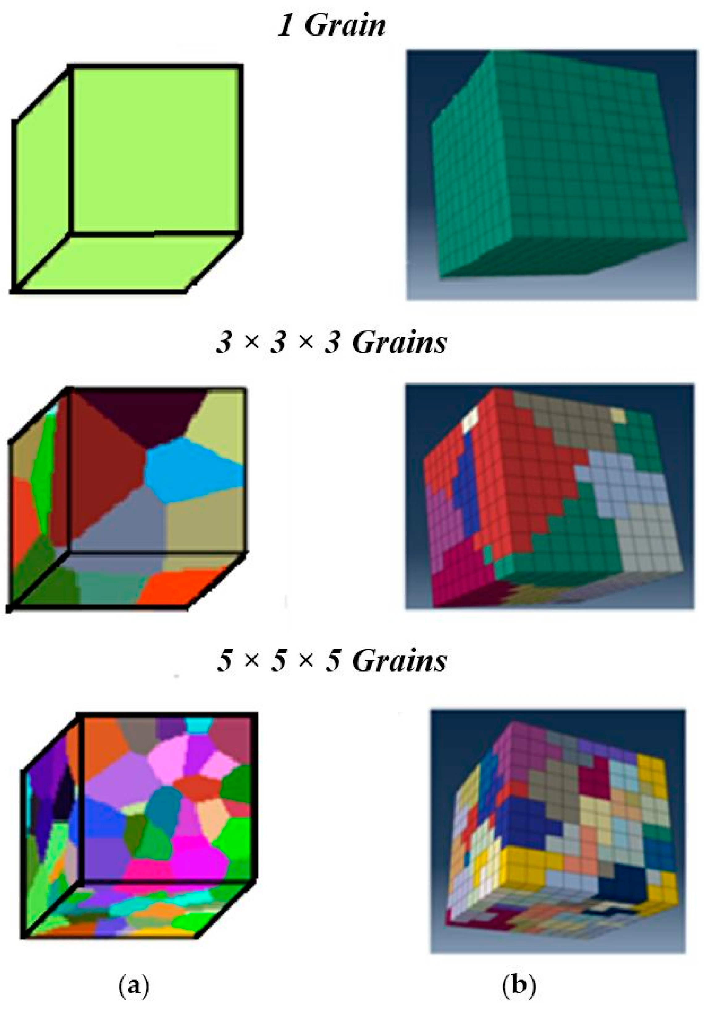
The GMC integrated with single crystal plasticity constitutive model is further verified by analyzing polycrystalline samples with additional grains and random orientations (
Figure 7).
The
n ×
n ×
n grains terminology refers to
n grains (roughly) in each dimension with a total of
n3 grains (exact) in the sample.
Figure 7a shows the grain geometry generated using Voronoi tessellations in MATLAB, and
Figure 7b shows the corresponding finite element and GMC models. The orientations were assigned according to the randomly selected orientation vectors for each of these grains. Overall, there is an agreeable match between the discretized model geometries and the target tessellation geometry. The slight mismatch is mainly because of the fact that the color coding is based on the element centroids for the finite element model, while the MATLAB script follows the exact surface. Hence, this approach of meshing the sample geometry first, followed by assigning the grain orientations to the elements based on their location of centroids rather than meshing the grain structure directly, has an inherent drawback in that it cannot match the grain geometry exactly. However, this can be reduced significantly by refining the mesh sufficiently to make element size much smaller than the grain size.
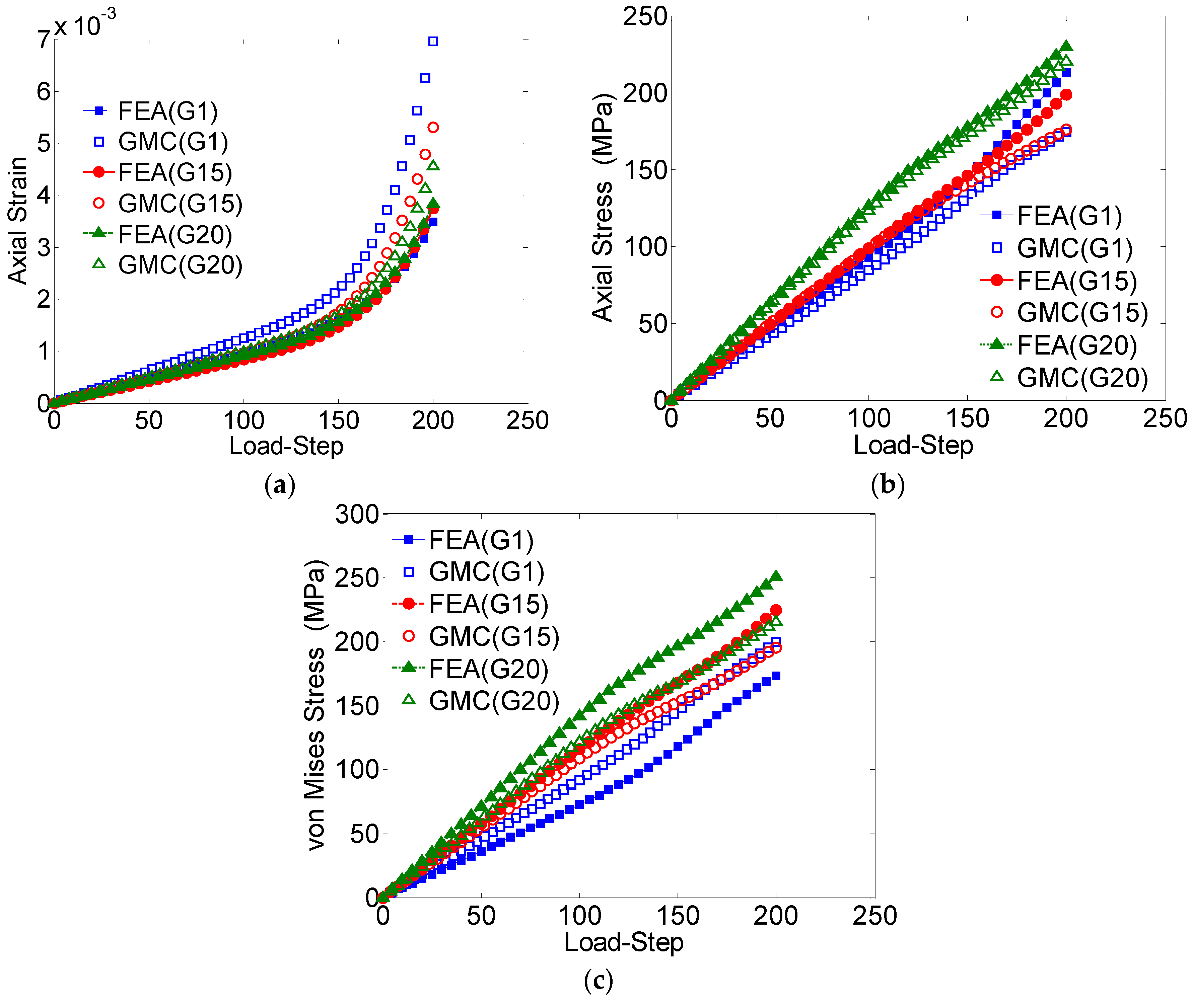
The GMC and FEA results are compared for the 3 × 3 × 3 grain sample under the uniaxial applied tensile loading (
Figure 8).
The average stress-strain behaviors obtained from both these methods, in all the three directions, are shown in
Figure 8. It can be observed that for the entire domain, the converged GMC solutions related to the axial stress (
Figure 8b) and von Mises stress (
Figure 8c) match well with the FEA solutions; however, the axial strain does not show good agreement. The axial strain, especially that obtained by FEA analysis, is a result of the anisotropy in the materials, which can be improved by increasing the number of grains in the sample.
The average values of field quantities in the individual grains, for the case of loading in the
z-direction, are further studied by comparing the behavior of three arbitrarily chosen grains (Grain numbers 1, 15 and 20) obtained by GMC and FEA (
Figure 9).
The axial strain (
Figure 9a) shows a relatively large difference, while the axial stress demonstrates excellent agreement. Though the difference was relatively larger for von Mises stress when compared to the axial stress, it was still within a reasonable range: around 15% error after the loading is completed. This difference can be attributed to the lack of normal-shear coupling in the GMC formulation, which introduces error in the stress concentrations near grain boundaries.
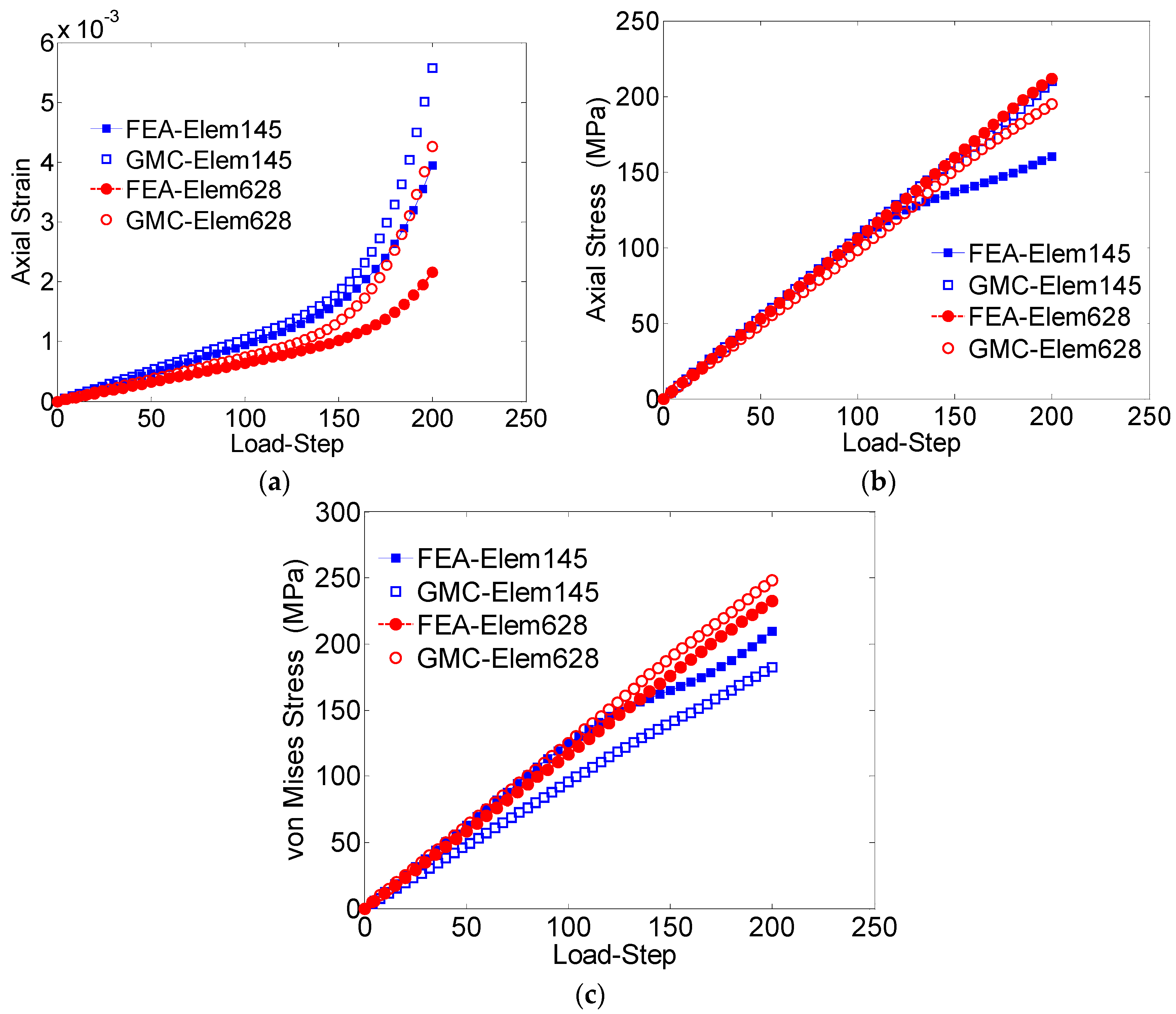
To further study the effectiveness of GMC, the results of two arbitrarily chosen subcells were compared with the corresponding elements in the FEA predictions. One of the studied elements/subcells was located far from the grain boundary (element 628), while the other (element 145) was in the region near boundary between the grains. The GMC and FEA results of the axial strain show significant difference (
Figure 10a) in each of the elements. The axial stress results agree closely for element 628, away from the boundary, while they demonstrate significant difference for element 145, which is closer to the boundary (
Figure 10b).
In the case of von Mises, element 628 has excellent agreement, while element 145, closer to the grain boundary, shows reasonable agreement. Even in the elastic regime, the GMC and FEA von Mises stresses differ because of additional shear stresses introduced through normal-shear coupling in the FEA model. A more detailed comparison is provided in
Table 3, which clearly shows that the GMC solution includes a maximum of 7% error when compared to FEA for the element far away from the grain boundary, but 17% error for the element closer to the grain boundary.
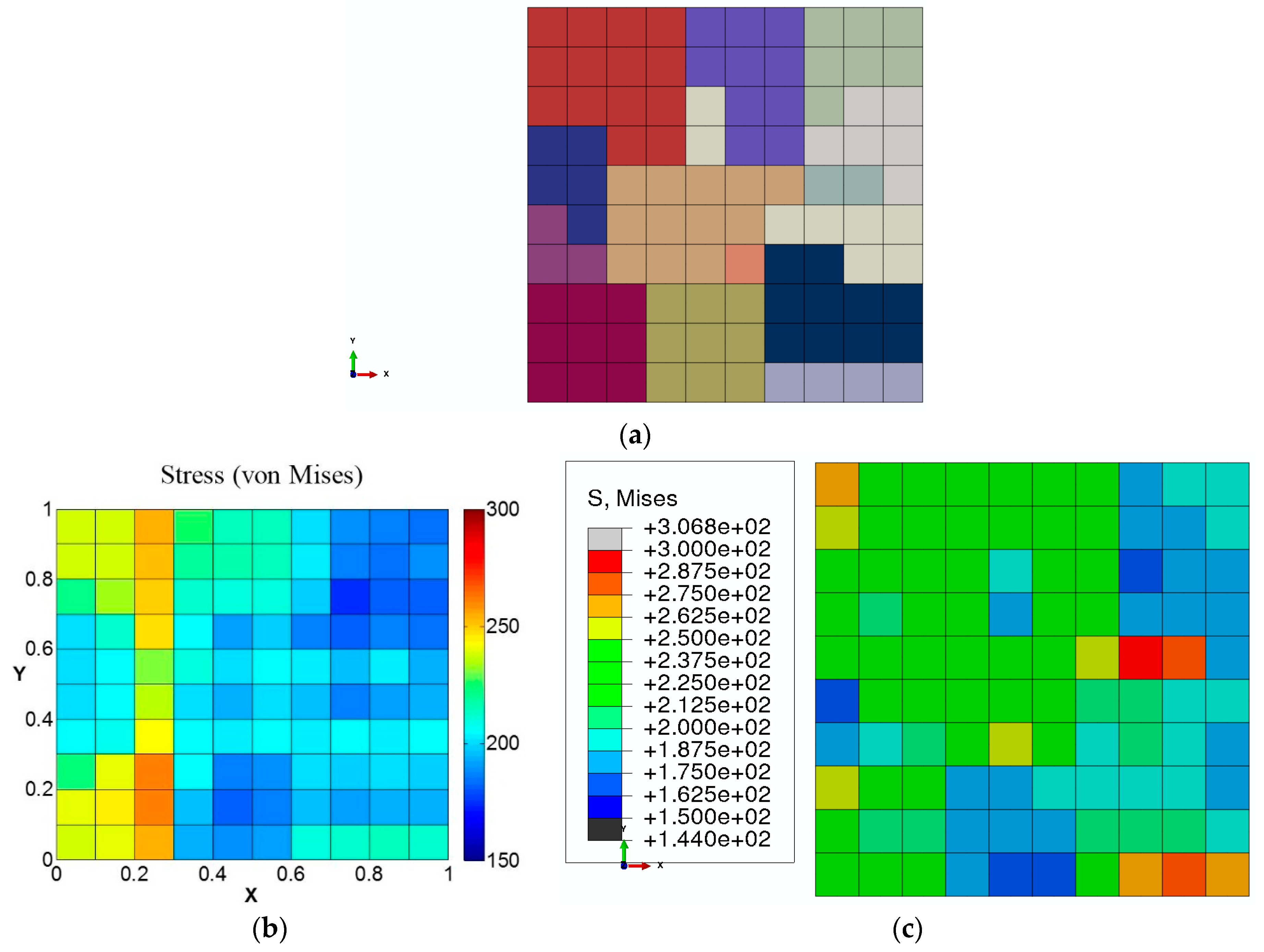
In addition, the von Mises stress distribution on the cross-section is compared in
Figure 11. It can be observed from the comparison that von Mises stress distribution determined by GMC agrees reasonably well with FEA in individual grains, though the gradient near the grain boundaries (as was also concluded from
Figure 10) is not captured as well in GMC.
The computational speeds were compared between GMC and FEA for three different cases: Case (1) a single crystal with one element/subcell; Case (2) 27-grain polycrystal with 1000 elements/subcells and Case (3) 125-grain polycrystal with 2744 elements/subcells (
Table 4). GMC demonstrated a significant reduction in the computational cost. The computational speeds of GMC were 90, 209 and 239 times faster than that of FEA for Cases 1, Case 2 and Case 3, respectively.
The significant savings in the computational cost in addition to the capability to predict the average RUC field quantities with minimal error make GMC homogenization a reliable and efficient method for analyzing large-size problems. Large stress gradients near the grain boundaries due to the abrupt change in the orientation of the grains adversely impact the local prediction accuracy of GMC due to the lack of normal-shear coupling, especially for the components of field tensor quantities averaged over the grains. However, the error on the prediction of effective quantities such as von Mises is within a reasonable range. The local values of the stress tensor components and the von Mises stress, determined at the element integration points, showed higher accuracy for the elements away from the grain boundary. Though the prediction error of the stress tensor components were relatively high for elements near the grain boundary, the error associated with the von Mises remained within reasonable limits. It is also important to note that the stress gradients near grain boundaries in real materials are not as sharp as that predicted by FEA due to various grain boundary deformation mechanisms and smoother grain boundaries. Hence, difference in the prediction between FEA and GMC decreases in a more realistic case than that observed in the present study. In summary, it can be stated based on the results from the present study that the GMC method can be used for extracting the effective von Mises stress (critical quantity for determining failure in metalic materials) at microscale with a reasonable accuracy, while reducing the computational cost significantly. Moreover, it is the average RUC stresses and strains that provide the link (i.e., “handshake”) between the macro- and microscales. Thus, the good agreement in the prediction of the average RUC fields demonstrates that GMC is a viable subscale tool for integration in a multiscale framework.
3.3. Disc
GMC integrated with the single crystal constitutive model is linked to macroscale through an FEA framework (FEAMAC) to develop the multiscale model that can analyze structural scale problems consisting of millions of grains. The macroscale strain, updated in each time-step, is determined at the integration points of the macroscale FEA elements. These integration point quantities are applied to the RUCs (microscale) homogenized by GMC, providing the average stresses, stiffness and inelastic strains back to the FEA (macroscale) integration point. For the purpose of demonstrating this functionality, a segment of a real-size turbine disk is analyzed. The disk is 254 long and is exposed to a centrifugal load ( with the magnitude of 6.3 (corresponding to the squared angular speed of 7 × 10⁸ ). Considering the symmetry of the geometry and the load, 1/8 of the disk is analyzed applying appropriate symmetric boundary conditions and 20-node brick elements. It is important to note that the symmetric assumption is valid strictly only at the macroscale. The violation of this assumption due to the anisotropy and inhomogeneity arising from the differences in grain orientations at microscale does not have any significant impact on the present demonstration study, and is hence ignored. The 3 × 3 × 3-grain polycrystal was used as the material model for each element in the microscale domain.
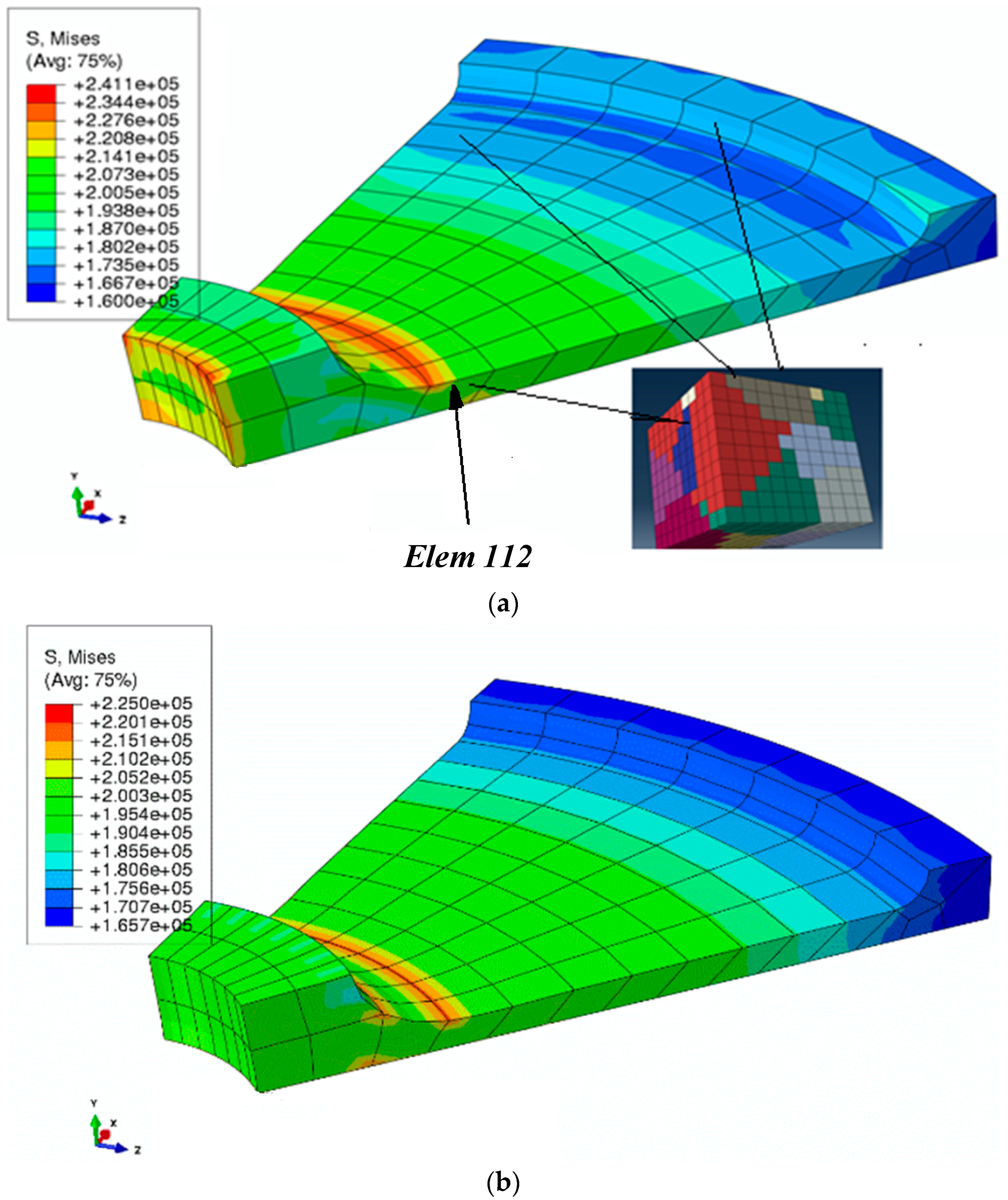
Figure 12a shows the von Mises stress distribution in the disk. To compare the macroscale stress distribution, the von Mises stress distribution obtained by using a standard finite element method (single scale) with a macroscale plasticity model is shown in
Figure 12b. In the standard FEA model, the global stress–strain curve obtained from the same 27-grain polycrystal under uniaxial loading was used as the constitutive model. It is important to note that the stress–strain variation per element in the standard FEA follows the element interpolation, while in the multiscale model the GMC can evaluate the stress–strain distribution at the microscale consistent with the interpolated macroscale values of the macroscale finite element.
The von Mises stress distributions shown in
Figure 12a,b demonstrate that the multiscale linking using GMC homogenization under a finite element framework predicts expected distribution at macroscale. The cross-sectional von Mises stress distribution for an element (Element 112), chosen arbitrarily, is shown in
Figure 13, and the element location is indicated in the model in
Figure 12a).
The distribution of the grain orientations on the chosen cross-section of the RUC and the von Mises stress distribution on this cross-section for two of the integration points of a random element (here Element 112) are demonstrated in
Figure 13a,b, respectively. In addition, the average von Mises stress distribution for all the integration points chosen on the previously defined RUC cross-section is shown in
Figure 13c. The results show that the local von Mises distribution at the grain-level in a real-sized model can be determined using the developed multiscale model, which is extremely computationally expensive, with a standard FEA approach.
4. Conclusions
A multiscale computational model was developed by employing the single crystal plasticity constitutive model at the microscale, in conjunction with GMC for homogenization, coupled to an FEA framework at the macroscale. In order to verify the effectiveness of GMC as a homogenization tool, the microscale behavior of single and polycrystalline samples were determined using the stand-alone GMC, and compared to that obtained from the standard FEA utilizing higher-order elements. For the polycrystals consisting of tens to hundreds of grains, GMC analysis achieved two–three orders of savings in computational cost at a minimal expense of accuracy in the components of both average and local tensor field quantities. The results based on GMC homogenization demonstrated reasonably good agreement with the FEA solution in terms of the von Mises and stress tensor components for the entire studied polycrystalline domain, the grain-averaged von Mises, von Mises and stress tensor components for elements away from the grain boundaries and von Mises for elements near the grain boundary. Therefore, the von Mises stress was found to be in a reasonably good agreement for all cases, making GMC a promising method for failure analysis applications.
Although the large gradient near the grain boundaries was not captured by GMC, the applicability of GMC homogenization is expected to be more effective in real materials where behavior does not vary at the grain boundaries as drastically as in the model due to various grain boundary deformation mechanisms. In addition, the accuracy of the local fields may not be pertinent in the absence of failure localization, as long as the average stress and strain quantities are accurate, since this is the mode for transmitting information across the scales in this multiscale framework.
Finally, the multiscale aspect of the model was demonstrated by implementing GMC as a homogenization tool on an FEA platform and investigating a real life turbine engine disc problem. The macroscale results demonstrated the expected stress distribution when compared to the FEA-based analysis, thereby verifying the method. The microscale distribution of von Mises stress was extracted on the cross-section of an arbitrarily selected element. The results demonstrated the multiscale capability of the developed multiscale model and may allow engineers to model variability in the microstructure spatially within a structural component and tailor the microstructure for different structural applications.


