Abstract
Junctionless (JL) thin-film transistors (TFTs) are promising candidates for low-cost, large-area electronic devices, but improvements in mobility and bias stability are still required. In this study, the effects of independent annealing of the indium oxide (InOx) channel layer and the aluminum oxide (AlOx) capping layer (CL) on the performance and reliability of InOx/AlOx heterostructure JL TFTs are examined. Devices were fabricated via solution deposition and photopatterning, and the InOx and AlOx layers were annealed at 250 °C and 400 °C. Increasing the annealing temperature from 250 °C to 400 °C, the InOx layer crystallized and densified. The AlOx layer remained amorphous at both temperatures, but its metal-hydroxyl content decreased with higher annealing. For both layers, JL TFTs annealed at 400 °C exhibited the best electrical performance (threshold voltage = 1.82 ± 0.40 V, subthreshold swing = 0.50 ± 0.07 V dec−1, saturation mobility = 1.57 ± 0.37 cm2 V−1 s−1). The threshold voltage shift under positive bias stress was 1.70 V, which demonstrates excellent bias stability. These results show that simultaneous high-temperature annealing of the channel and CL is essential to reduce trap-assisted scattering and stabilize electrostatics in JL TFTs, providing practical process guidelines for bias-stable and high-performance oxide electronics.
1. Introduction
Oxide semiconductor (OS)-based thin-film transistors (TFTs) have emerged as key building blocks for next-generation electronics owing to their wide bandgap nature that enables high optical transparency, strong stability under high electric fields, and high breakdown voltage, as well as their inherent advantages of very low leakage current and compatibility with low-temperature (<400 °C) processing [1,2,3,4]. OS technology has successfully replaced hydrogenated amorphous silicon in displays and has become the standard backplane for organic light-emitting diode panels [5]. Beyond displays, OS TFTs show strong potential for back-end-of-line compatible transistor applications in monolithic three-dimensional integration and are increasingly investigated for optoelectronics, sensors, and neuromorphic computing [6,7,8].
OS-based junctionless (JL) TFTs are attracting attention because their architecture simplifies fabrication by eliminating source-drain (S-D) junction formation and reducing the overall process complexity and cost [9,10]. The advantages of JL TFTs become even greater when they are implemented through solution process with solution-compatible, photolithography-free patterning methods. However, conventional OS TFTs are typically fabricated via mature vacuum processes (e.g., sputtering) and conventional photolithography [11,12,13]. These OS TFTs generally exhibit excellent electrical characteristics and reliability. Recent studies have reported field-effect mobility comparable to that of low-temperature polycrystalline silicon TFTs [14,15]. In contrast, OS TFTs fabricated using solution process often exhibit relatively low mobility and reliability [16]. This suggests that while using solution process is attractive to maximize the benefits of JL TFTs, improvements in electrical performance and reliability are still required.
In solution-processed JL TFTs, the channel and conductive S–D regions are defined by the selective formation of an oxide capping layer (CL) that modulates carrier concentration of the channel. Heterostructures such as indium oxide/aluminum oxide (InOx/AlOx) are promising, as the AlOx CL both passivates the back channel and suppresses excess carriers in the InOx channel [17]. Precise control of carrier concentration in the channel and S–D regions is crucial, since excessive conductivity prevents full depletion under negative gate bias, while overly resistive S–D regions reduce on current and saturation mobility (μSAT) [18]. Therefore, co-optimizing the channel and CL properties (balancing carrier concentration, trap density, and structural quality) is essential. This requires understanding how thermal treatment of semiconductor and CLs affects electron concentration, defect states, and crystallinity, and consequently determines key device parameters such as threshold voltage (VT) and subthreshold swing (SS).
In addition, for n-type OS TFT-based display backplanes and integrated driver circuits, robustness under positive bias stress (PBS) is a key performance indicator because the devices are repeatedly subjected to positive gate bias [19]. The threshold voltage shift (ΔVT) under bias directly affects pixel current accuracy and lifetime uniformity. Therefore, optimizing the thermal annealing of both the semiconductor layer and the CL in JL heterostructures is crucial for ensuring device reliability [20].
In this study, we systematically examine the effects of annealing combinations of the InOx semiconductor and AlOx CL on the electrical characteristics and reliability of solution-processed InOx/AlOx heterojunction JL TFTs. The devices were fabricated using a minimal and efficient process based on solution deposition and photopatterning. The InOx and AlOx layers were each annealed at either 250 °C or 400 °C to generate the target combinations. To clarify how the channel and CL properties affect device behavior, transmission electron microscopy (TEM), X-ray photoelectron spectroscopy (XPS), and X-ray reflectivity (XRR) were employed. The contact and channel resistances were separated using the transmission line method (TLM) to isolate the effect of heat treatment on the resistance components.
The bias stability of the device was then evaluated through PBS test. The results revealed that annealing not only InOx but also AlOx significantly improved μSAT and reduced SS. Furthermore, simultaneous high-temperature annealing of InOx and AlOx produced the most favorable device characteristics—namely, the highest μSAT, lowest SS, and an appropriate positive VT, and the smallest ΔVT under PBS—thereby providing a clear pathway toward high-performance, bias-stable JL TFTs.
2. Materials and Methods
2.1. Preparation of Oxide Precursor Solutions
InOx and AlOx precursor solutions were prepared for JL TFT fabrication. A 0.1 M InOx solution was synthesized by dissolving indium nitrate hydrate (In(NO3)3·xH2O) in 2-methoxyethanol (2-ME). A 0.3 M AlOx solution was prepared by dissolving aluminum nitrate nonahydrate (Al(NO3)3·9H2O) in 2-ME. All solutions were prepared 24 h before use. The mixtures were stirred at 50 °C for 12 h and then aged under ambient conditions for 12 h to obtain clear, homogeneous solutions.
2.2. Fabrication of Devices
Heavily doped p-type silicon wafers with a 100 nm thermally grown SiO2 gate dielectric were cleaned by sequential ultrasonication in acetone, isopropyl alcohol, and deionized (DI) water for 10 min each. Ultraviolet (UV)-ozone treatment was then performed to remove organic residues and improve surface hydrophilicity. The InOx solution was spin-coated onto the SiO2/p-type Si substrates at 3000 rpm for 20 s. In this configuration, the p-type Si and SiO2 serve as the gate and gate insulator, respectively. Patterning of the oxide films was carried out using a water etchant-based photopatterning method previously reported [21]. The substrates were soft-baked at 100 °C for 10 s, followed by UV-ozone treatment through a fine metal mask for 3 min. After exposure, the mask was removed, and the substrates were developed by DI water etching for 1 min. The UV-patterned InOx layers were pre-annealed at 100 °C for 5 min and then post-annealed at either 250 °C or 400 °C for 1 h in ambient air. The AlOx solution was spin-coated onto the InOx layer at 3000 rpm for 20 s. The same photopatterning procedure was used to define the channel regions, with soft-bake and UV exposure times optimized for AlOx. Since the concentration and thickness of solution-processed films tend to be proportional, the AlOx layer formed under the same coating and annealing conditions was approximately three times thicker than the InOx layer. The patterned AlOx CLs were pre-annealed at 100 °C for 5 min and then post-annealed at either 250 °C or 400 °C for 1 h in ambient air. Three types of TFTs were fabricated with different heat-treatment combinations. InOx films annealed at 250 °C and 400 °C are denoted as InO-250 and InO-400. Likewise, AlOx films annealed at 250 °C and 400 °C are denoted as AlO-250 and AlO-400. The channel length (Lch) and width (Wch) of all devices were 100 μm and 500 μm, respectively.
2.3. Analysis of Thin Films and Devices
The chemical composition of the InOx and AlOx films was characterized by X-ray photoelectron spectroscopy (XPS, NEXSA, Thermo Fisher Scientific, Waltham, MA, USA) using an Al Kα radiation source (1486.6 eV). For the quantitative analysis of film density, X-ray reflectivity (XRR, ATX-G, Rigaku, Tokyo, Japan) measurements were performed to evaluate the film density of InOx and AlOx. For accurate XRR analysis of film density, a film thickness exceeding 5 nm was required. Both 0.3 M indium oxide and 0.3 M aluminum oxide precursor solutions were used to prepare the films. The density values were extracted by fitting the Kiessig fringes in the XRR spectra, providing reliable and quantitative estimation of the mass density based on electron density contrast. The electrical characteristics of the TFTs were measured with a semiconductor parameter analyzer (4200A-SCS, Keithley, Cleveland, OH, USA). All measurements were conducted at room temperature under dark conditions. VT was determined by the constant current method, defined as the gate voltage (VG) that induces a drain current (ID) = 10 nA × Wch Lch−1. SS was obtained from the subthreshold region in the current range of ID = 1 to 10 nA, based on the following equation:
The I–V characteristics in the saturation region are described by the following equation [22]:
COX denotes gate capacitance per unit area of the insulator layer. μSAT was extracted at VG = VT + 10 V with the drain voltage (VD) = 30 V. The contact resistance (RC) and channel sheet resistance (RSH) were calculated using the transmission line method (TLM) with the following equation [23]:
3. Results and Discussion
3.1. Concept and Operation of JL TFTs
The device proposed in this study is a JL TFT composed of an InOx semiconductor and an AlOx CL. Figure 1a,b illustrate the fabrication process flow and the device architecture, respectively. Figure 1c presents an optical microscope image of the fabricated JL TFT, where the Lch, Wch, and offset region (Loffset) are defined. Similarly to conventional TFT structures, a short Lch is desirable for high on-state current, but short-channel effects must be considered. Furthermore, a short Loffset contributes to lowering the contact resistance of the device. In this work, Lch, Wch, and Loffset were fixed at 100, 500, and 400 μm, respectively, for all devices. The transfer characteristics of JL TFTs with and without the AlOx CL are shown in Figure 1d to verify the functional role of the CL. Devices without AlOx exhibited no discernible switching, indicating which confirms that the CL is essential for enabling switching operation. Figure 1e schematically depicts the underlying mechanism. During thermal annealing, Al and O diffuse into the InOx layer, suppressing the electron concentration by reducing the oxygen vacancy (VO) density to a level suitable for TFT operation [24]. The observed decrease in electron concentration near the InOx/AlOx interface can be attributed to the strong oxygen affinity of Al. During the capping process, partial Al–O interdiffusion occurs, which suppresses oxygen vacancies in the underlying InOx layer. As oxygen vacancies act as electron donors in InOx-based oxides, their reduction lowers the free-electron density and shifts the Fermi level toward the mid-gap. Consequently, the conduction-band minimum is raised, resulting in reduced carrier concentration near the interface [25,26,27]. As a result, the InOx-only film remains highly conductive and cannot be fully depleted, whereas diffusion from the AlOx CL modulates the conductivity of InOx. This CL-driven carrier modulation is the key principle that enables JL TFT operation.
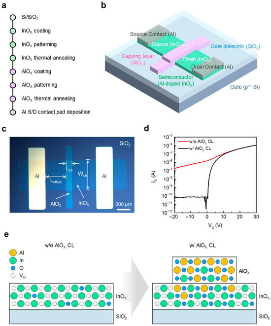
Figure 1.
(a) Fabrication process flow of solution-processed InOx/AlOx JL TFTs. (b) Schematic illustration of the fabricated JL TFT. (c) Optical microscope image of a representative device, showing the defined Lch, Wch, and Loffset. (d) Transfer characteristics of JL TFTs with and without the AlOx CL (e) Schematic illustration comparing the atomic structure of InOx with and without the AlOx CL.
3.2. Effects of Annealing Temperature on the Structural and Chemical Characteristics of the InOx Semiconductor and AlOx CL
To investigate the structural effects of annealing temperature on the InOx/AlOx stack, cross-sectional TEM analyses were performed. Figure 2a–c show TEM images of InO-250/AlO-250, InO-400/AlO-250, and InO-400/AlO-400 stacked films, respectively. A well-defined bilayer is observed in all cases. The AlOx layer exhibits a relatively uniform, amorphous phase regardless of annealing condition, which is consistent with the known amorphous nature of AlOx even at high annealing temperatures. To assess crystallinity, the corresponding fast Fourier transform (FFT) patterns are shown in Figure 2d–f. In the InO-250/AlO-250 sample, the InOx layer exhibits a diffused halo, which is characteristic of amorphous materials. In contrast, the InO-400/AlO-250 sample exhibits discernible diffraction spots, while the InO-400/AlO-400 sample shows sharper, more distinct spots, indicative of a higher crystalline fraction. These results confirm that InOx undergoes a significant amorphous-to-crystalline transition at 400 °C, forming an ordered matrix that is expected to reduce structural disorder and facilitate charge transport. By comparison, AlOx remains amorphous under all annealing conditions, as corroborated by its FFT halos. The absence of grain boundaries in amorphous AlOx supports its role as a passivation layer that effectively blocks moisture and oxygen from the environment.
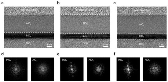
Figure 2.
TEM images of the InOx/AlOx heterostructure: (a) InO-250/AlO-250, (b) InO-400/AlO-250, and (c) InO-400/AlO-400. Corresponding FFT patterns for (d) InO-250/AlO-250, (e) InO-400/AlO-250, and (f) InO-400/AlO-400.
XPS was employed to analyze changes in chemical bonding in InOx and AlOx as a function of annealing temperature. All spectra were calibrated to the C 1s reference at 284.8 eV. The O 1s envelope was deconvolved into three Gaussian components at approximately 530.15, 530.86, and 532.07 eV, corresponding to lattice metal–oxygen bonds (M–O), VO, and metal–hydroxide (M–OH), respectively. Figure 3a compares the O 1s spectra of InO-250 (left) and InO-400 (right). The relative fractions of M–O, VO, and M–OH were 63.7%, 20.3%, and 15.9% for InO-250 and 70.1%, 20.9%, and 8.3% for InO-400, respectively. These results indicate that high-temperature annealing effectively removes hydroxyl species, thereby strengthening M–O bonding and stabilizing the oxide network. A similar trend was observed in AlOx (Figure 3b), where the M–OH fraction decreased from 32.3% to 29.4% and the M–O fraction increased from 67.7% to 70.8% with higher annealing temperature. Figure 3c,d shows In 3d spectra of InOx and Al 2p spectra of AlOx films, respectively. The In 3d spectrum exhibits two well-defined peaks at approximately 444.5 eV (In 3d5/2) and 452.0eV (In 3d3/2), corresponding to the spin–orbit doublet characteristic of fully oxidized In3+ in InOx. No metallic indium component was detected, confirming complete oxidation of the InOx layer. Similarly, the Al 2p spectrum shows a single sharp peak centered at ~74.4 eV, consistent with Al3+ in AlOx. These results indicate that both InOx and AlOx films maintain stable stoichiometric oxide states without sub-oxide or metallic phases. XRR data are shown in Figure 3e,f for InOx and AlOx, respectively. In InOx, the density increased from 5.67 g cm−3 (InO-250) to 6.19 g cm−3 (InO-400), while the thickness decreased from 14.12 nm (InO-250) to 11.43 nm (InO-400) by increasing the annealing temperature. The film thickness, density, and surface roughness of the InOx and AlOx films are summarized in Table 1. These changes are consistent with densification during annealing and align with TEM and FFT evidence of crystallization at 400 °C. By contrast, AlOx exhibited negligible changes in density and thickness between 250 °C and 400 °C, supporting the conclusion that annealing strongly affects InOx crystallinity and densification, while its impact on AlOx is comparatively minor within this temperature range.
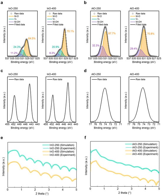
Figure 3.
XPS O 1s spectra of (a) InO-250 (left) and InO-400 (right), and (b) AlO-250 (left) and AlO-400 (right). XPS In 3d spectra of (c) InO-250 (left) and InO-400 (right). XPS Al 2p spectra of (d) AlO-250 (left) and AlO-400 (right). XRR spectra of (e) InO-250 and InO-400 and (f) AlO-250 and AlO-400.

Table 1.
The film thickness, density, and surface roughness of the InOx and AlOx films.
3.3. Electrical Characteristics of InOx/AlOx Heterostructure JL TFTs
To correlate structural and chemical evolution with device operation, the electrical characteristics of the three JL TFT types were evaluated. Figure 4a–c present the output characteristics of InO-250/AlO-250, InO-400/AlO-250, and InO-400/AlO-400 JL TFTs, respectively. For these measurements, VG was varied from 0 to 30 V in 5 V intervals, and VD was swept from 0 to 30 V at a fixed VG. All devices exhibited well-defined linear and saturation regions, which confirms proper channel formation. ID increased monotonically with annealing temperature, consistent with enhanced charge transport resulting from denser, crystallized InOx and AlOx films with fewer traps.
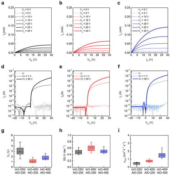
Figure 4.
Output characteristics of (a) InO-250/AlO-250, (b) InO-400/AlO-250, and (c) InO-400/AlO-400 JL TFTs. Transfer characteristics of (d) InO-250/AlO-250, (e) InO-400/AlO-250, and (f) InO-400/AlO-400 JL TFTs. Box plots of extracted electrical parameters: (g) VT, (h) SS, and (i) μSAT.
Figure 4d–f show the transfer characteristics measured by sweeping VG from −20 to +30 V at fixed VD values of 1 V and 30 V. All devices exhibited low off currents and gate leakage currents on the order of 10−12–10−10 A, which is attributed to effective patterning and isolation of the active region [28]. Figure 4g–i summarize the extracted parameters. The VT values of InO-250/AlO-250, InO-400/AlO-250, and InO-400/AlO-400 were 2.95 ± 0.89 V, 1.07 ± 0.57 V, and 1.82 ± 0.40 V, respectively (Figure 4g). The largest VT observed in InO-250/AlO-250 is attributed to the nearly amorphous, poorly conductive InOx channels containing deep defects [29]. In contrast, the lowest VT in InO-400/AlO-250 is plausibly linked to the higher electron density of crystallized InOx combined with hydrogen-related states remaining in low-temperature AlOx and insufficient suppression of VO in InOx by AlOx diffusion. Annealing AlOx at 400 °C mitigates –OH–related defects and appropriately reduces electron density, which produces a positive VT shift and a more stable turn-on even with the same InO-400 channel.
The SS values were 0.48 ± 0.07 V dec−1 (InO-250/AlO-250), 0.62 ± 0.13 V dec−1 (InO-400/AlO-250), and 0.50 ± 0.07 V dec−1 (InO-400/AlO-400) (Figure 4h). SS in JL TFTs reflects the combined influence of interface/bulk traps and the depletion capacitance (Cdep). Although InO-250/AlO-250 exhibits a small SS, thin film analysis does not necessarily indicate a low trap density. Instead, the lower apparent SS likely arises from reduced electron density, which allows for efficient depletion (smaller Cdep). By contrast, InO-400/AlO-250 shows the largest SS, consistent with the combined effects of higher channel electron density (larger Cdep) and residual –OH–related traps in AlO-250. The InO-400/AlO-400 device achieves a low SS by combining a crystalline, adequately doped InOx channel with a trap-suppressed AlOx CL. The SS of conventional solution-processed oxide TFTs was at the values of 0.36 to 4.87, and the SS of the junctionless device proposed in this study was at a comparable value [29,30,31].
The μSAT values were 0.50 ± 0.14, 0.79 ± 0.14, and 1.57 ± 0.37 cm2 V−1 s−1 for InO-250/AlO-250, InO-400/AlO-250, and InO-400/AlO-400 JL TFTs, respectively (Figure 4i). Crystallization and reduced structural disorder from densification of InOx at 400 °C contributed to the improvement in μSAT.
In addition, the suppression of interface scattering and trapping through annealing of AlOx at 400 °C further enhanced μSAT, as reflected in the trends across the three devices. Consequently, the InO-400/AlO-400 device exhibited the highest μSAT.
3.4. Contact and Channel Resistance of InOx/AlOx Heterostructure JL TFTs
The TLM was used to separate the contact and channel contributions. Figure 5a–c show the width-normalized total resistance (RTotal·W) as a function of Lch, for InO-250/AlO-250, InO-400/AlO-250, and InO-400/AlO-400 JL TFTs, respectively. Transfer curves were measured in the linear region (VD = 1 V) for devices with variable channel lengths on the same wafer. The RTotal·W–Lch plots were highly linear under all conditions. The intercept yields the RC·W, and the slope yields RSH. As expected, both RC·W and RSH decrease with increasing gate overdrive voltage (VOV) = VG − VT, reflecting the simultaneous mitigation of the metal/semiconductor injection barrier and carrier scattering as the accumulated charge increases.
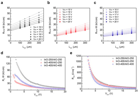
Figure 5.
VOV-dependent RTotal·W variations in the (a) InO-250/AlO-250, (b) InO-400/AlO-250, and (c) InO-400/AlO-400 TFTs. Extracted (d) RC·W and (e) RSH of the devices as a function of VOV.
Among the three types of devices, InO-250/AlO-250 exhibited the largest RC·W and RSH at VOV (Figure 5d,e). This is attributed to the amorphous, low-density InOx containing abundant –OH defects, which degrade the channel conduction and simultaneously increase the resistance of Loffset. These results are consistent with TEM, XPS, and XRR findings. In InO-400/AlO-250, both resistances decreased significantly at 400 °C because crystallization and densification of InOx enhanced injection and bulk transport. However, RSH remained higher than in InO-400/AlO-400, which suggests that residual –OH-related defects in AlO-250 still induced scattering and trapping near the channel. InO-400/AlO-400 devices exhibited the lowest RSH across the entire bias range, and RC·W were comparable to (or lower than) those of InO-400/AlO-250, indicating that both channel and contact were optimized simultaneously. These TLM results are consistent with the I-V characteristics in Figure 4. While the high RC·W and RSH in InO-250/AlO-250 led to low μSAT, InO-400/AlO-400 achieved the highest μSAT by reducing both RC·W and RSH and suppressing interface traps to maintain a low surface potential.
3.5. Positive Bias Stability of InOx/AlOx Heterostructure JL TFTs
Bias reliability is a critical performance metric for practical applications. We therefore performed PBS tests at a stress overdrive voltage (VSTR) of 20 V. Figure 6a–c show the transfer curve evolution with stress time for InO-250/AlO-250, InO-400/AlO-250, and InO-400/AlO-400, respectively, and Figure 6d–f summarize the corresponding time dependence of ΔVT. The VT of the InO-250/AlO-250 JL TFT gradually shifted in the positive direction, reaching a large ΔVT = 6.22 V. This is attributed to the effective electron trapping caused by the high trap densities of the InOx and AlOx thin films. By contrast, the InO-400/AlO-250 and InO-400/AlO-400 JL TFTs exhibited much smaller final ΔVT values of 1.78 V and 1.70 V, respectively, owing to defect reduction by thermal annealing.
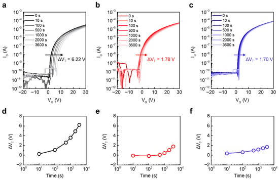
Figure 6.
Evolution of the transfer characteristics of (a) InO-250/AlO-250, (b) InO-400/AlO-250, and (c) InO-400/AlO-400 JL TFTs under PBS with VSTR of 20 V. Time-dependent ΔVT under PBS of (d) InO-250/AlO-250, (e) InO-400/AlO-250, and (f) InO-400/AlO-400 JL TFTs.
A notable feature in Figure 6e is the non-monotonic ΔVT observed for InO-400/AlO-250. The ΔVT initially shifted negatively (t ≤ 100 s) and then reversed to a positive shift, ultimately converging to 1.78 V. This sign reversal points to the role of low-temperature AlOx. Consistent with the XPS results, AlO-250 retained a higher M–OH fraction than AlO-400, which can supply hydrogen-related species. Under positive gate bias, H+ can drift toward the interface/channel or be injected into InOx, transiently increasing interfacial positive charge or forming shallow hydrogen-related donors. This process produces the initial negative ΔVT. As stress continues, electron trapping at deeper states becomes dominant, which drives ΔVT back to positive values. In InO-400/AlO-400 JL TFTs, –OH species were effectively removed, so the H+ contribution was minimal. The initial negative component was therefore absent, and the overall ΔVT remained small. Thus, the non-monotonic behavior in Figure 6e serves as a sensitive indicator of hydrogen-related defects in low-temperature AlOx and quantitatively underscores the importance of high-temperature AlOx annealing to ensure PBS stability.
4. Conclusions
A systematic study of InOx/AlOx JL TFTs fabricated via a solution process was performed to clarify the relationship between processing conditions, film properties, and device performance, which enables device optimization. Independently varying the annealing temperature in the InOx/AlOx heterostructure revealed that high-temperature treatment at 400 °C crystallized and densified InOx, while suppressing –OH-related interface traps in AlO-400 without altering its amorphous nature. This temperature-dependent understanding of film properties enabled simultaneous optimization of channel transport and contact characteristics. Consequently, InO-400/AlO-400 devices were realized with an optimal configuration. This device demonstrated the following performance parameters: VT = 1.82 ± 0.40 V, SS = 0.50 ± 0.07 V dec−1, μSAT = 1.57 ± 0.37 cm2 V−1 s−1, including the smallest PBS mobility (ΔVT = 1.70 V), and the lowest RC·W and RSH under TLM. By contrast, InO-400/AlO-250 exhibited large SS, relatively low μSAT, and non-monotonic ΔVT under PBS due to –OH-related defects in low-temperature AlOx, an instability that was resolved by annealing AlOx at 400 °C. These results demonstrate that capping-induced carrier modulation and interface trap control are the key determinants of device performance and stability.
Author Contributions
Conceptualization, J.P., D.-K.K. and J.-H.B.; methodology, J.P. and J.W.A.; validation, J.P.; formal analysis, D.G., S.J.P. and M.C.; investigation, D.-K.K. and J.-H.B.; resources, J.J. and P.L.; data curation, J.P. and D.-K.K.; writing—original draft preparation, J.P.; writing—review and editing, D.-K.K. and J.-H.B.; supervision, D.-K.K. and J.-H.B. All authors have read and agreed to the published version of the manuscript.
Funding
This work was partly supported by the Institute of Information & Communications Technology Planning & Evaluation (IITP)-Innovative Human Resource Development for Local Intellectualization program grant funded by the Korea government (MSIT) (IITP-2025-RS-2022-00156389, 50%) and also supported by 2024 Research Grant from Kangwon National University.
Data Availability Statement
The original contributions presented in this study are included in the article. Further inquiries can be directed to the corresponding authors.
Conflicts of Interest
The authors declare no conflicts of interest.
References
- Fortunato, E.; Barquinha, P.; Martins, R. Oxide Semiconductor Thin-Film Transistors: A review of Recent Advances. Adv. Mater. 2012, 24, 2945–2986. [Google Scholar] [CrossRef]
- Kamiya, T.; Hosono, H. Material characteristics and applications of transparent amorphous oxide semiconductors. NPG Asia Mater. 2010, 2, 15–22. [Google Scholar] [CrossRef]
- Ishibe, T.; Tomeda, A.; Komatsubara, Y.; Kitaura, R.; Uenuma, M.; Uraoka, Y.; Yamashita, Y.; Nakamura, Y. Carrier and phonon transport control by domain engineering for high-performance transparent thin film thermoelectric generator. Appl. Phys. Lett. 2021, 118, 151601. [Google Scholar] [CrossRef]
- Gong, L.; Wei, M.; Yu, R.; Ohta, H.; Katayama, T. Significant Suppression of Cracks in Freestanding Perovskite Oxide Flexible Sheets Using a Capping Oxide Layer. ACS Nano 2022, 16, 21013–21019. [Google Scholar] [CrossRef] [PubMed]
- Park, J.S.; Maeng, W.-J.; Kim, H.-S.; Park, J.-S. Review of recent developments in amorphous oxide semiconductor thin-film transistor devices. Thin Solid Films 2012, 520, 1679–1693. [Google Scholar] [CrossRef]
- Jang, Y.; Park, J.; Kang, J.; Lee, S.-Y. Amorphous InGaZnO (a-IGZO) Synaptic Transistor for Neuromorphic Computing. ACS Appl. Electron. Mater. 2022, 4, 1427–1448. [Google Scholar] [CrossRef]
- Choi, Y.; Park, W.-Y.; Kang, M.S.; Yi, G.-R.; Lee, J.-Y.; Kim, Y.-H.; Cho, J.H. Monolithic Metal Oxide Transistors. ACS Nano 2015, 9, 4288–4295. [Google Scholar] [CrossRef]
- Yu, X.; Marks, T.J.; Facchetti, A. Metal oxides for optoelectronic applications. Nat. Mater. 2016, 15, 383–396. [Google Scholar] [CrossRef]
- Kim, J.H.; Rim, Y.S.; Kim, H.J. Homojunction Solution-Processed Meta Oxide Thin-Film Transistors Using Passivation-Induced Channel Definition. ACS Appl. Mater. Interfaces 2014, 6, 4819–4822. [Google Scholar] [CrossRef]
- Hong, S.; Na, J.W.; Lee, I.S.; Kim, H.T.; Kang, B.H.; Chung, J.; Kim, H.J. Simultaneously Defined Semiconducting Channel Layer Using Electrohydrodynamic Jet Printing of a Passivation layer for Oxide Thin-Film Transistors. ACS Appl. Mater. Interfaces 2020, 12, 39705–39712. [Google Scholar] [CrossRef]
- Kim, H.J.; Park, K.; Kim, H.J. High-performance vacuum-processed metal oxide thin-film transistors: A review of recent developments. J. Soc. Inf. Disp. 2020, 28, 591–622. [Google Scholar] [CrossRef]
- Kumomi, H.; Nomura, K.; Kamiya, T.; Hosono, H. Amorphous oxide channel TFTs. Thin Solid Films 2008, 516, 1516–1522. [Google Scholar] [CrossRef]
- Tückmantel, C.; Kalita, U.; Haeger, T.; Theisen, M.; Pfeiffer, U.; Riedl, T. Amorphous indium-gallium-zinc-oxide TFTs patterned by self-aligned photolithography overcoming the GHz threshold. IEEE Electron Device Lett. 2020, 41, 1786–1789. [Google Scholar] [CrossRef]
- Saha, J.K.; Jang, J. Saturation Mobility of 100 cm2 V–1 s–1 in ZnO Thin-Film Transistors through Quantum Confinement by a Nanoscale In2O3 Interlayer Using Spray Pyrolysis. ACS Nano 2024, 18, 30484–30496. [Google Scholar] [CrossRef] [PubMed]
- Wen, P.; Peng, C.; Ding, X.; Chen, F.H.; Yan, G.; Xu, L.; Li, J.; Li, X.; Zhang, J. High mobility crystallized stacked-channel thin-film transistors induced by low-temperature thermal annealing. Appl. Phys. Lett. 2025, 126, 023506. [Google Scholar] [CrossRef]
- Ahn, B.D.; Jeon, H.-J.; Sheng, J.; Park, J.; Park, J.-S. A review on the recent developments of solution processes for oxide thin film transistors. Semicond. Sci. Technol. 2015, 30, 064001. [Google Scholar] [CrossRef]
- Ding, Y.; Fan, C.; Fu, C.; Meng, Y.; Liu, G.; Shan, F. High-performance indium oxide thin-film transistors with aluminum oxide passivation. IEEE Electron Device Lett. 2019, 40, 1949–1952. [Google Scholar] [CrossRef]
- Lee, K.; Kim, Y.-H.; Yoon, S.-M.; Kim, J.; Oh, M.S. Effects of channel thickness on oxide thin film transistor with double-stacked channel layer. J. Korean Phys. Soc. 2017, 71, 561–564. [Google Scholar] [CrossRef]
- Conley, J.F. Instabilities in amorphous oxide semiconductor thin-film transistors. IEEE Trans. Device Mater. Reliab. 2010, 10, 460–475. [Google Scholar] [CrossRef]
- Zheng, S.; Wang, C.; Lv, S.; Dong, L.; Li, Z.; Xin, Q.; Song, A.; Zhang, J.; Li, Y. Enhancement in Performance and Reliability of Fully Transparent a-IGZO Top-Gate Thin-Film Transistors by a Two-Step Annealing Treatment. Nanomaterials 2025, 15, 460. [Google Scholar] [CrossRef]
- Kim, D.-K.; Seo, K.-H.; Kwon, D.-H.; Jeon, S.-H.; Hwang, Y.-J.; Wang, Z.; Park, J.; Lee, S.-H.; Jang, J.; Kang, I.M.; et al. Viable strategy to minimize trap states of patterned oxide thin films for both exceptional electrical performance and uniformity in sol–gel processed transistors. Chem. Eng. J. 2022, 441, 135833. [Google Scholar] [CrossRef]
- Acharya, V.; Agarwal, K.; Mondal, S. Electronic materials for solution-processed TFTs. Mater. Res. Express 2023, 10, 082002. [Google Scholar] [CrossRef]
- Nguyen, C.P.C.; Trinh, T.T.; Raja, J.; Le, A.H.T.; Lee, Y.-J.; Dao, V.A.; Yi, J. Source/drain metallization effects on the specific contact resistance of indium thin zinc oxide thin film transistors. Mater. Sci. Semicond. Process 2015, 39, 649–653. [Google Scholar] [CrossRef]
- Lee, J.; Eun, J.-S.; Na, J.-H.; Park, W.; Park, J.-H.; Feng, J.; Jang, J.; Kang, I.M.; Park, J.; Zhang, X.; et al. Verifying the physical role of upper-active layer on charge transport together with bias stability in bilayer-channel oxide thin-film transistors. Surf. Interfaces 2024, 51, 104624. [Google Scholar] [CrossRef]
- Kim, T.H.; Park, W.; Oh, S.; Kim, S.-Y.; Yamada, N.; Kobayashi, H.; Jang, H.Y.; Nam, J.H.; Habazaki, H.; Lee, B.H.; et al. Unveiling the Role of Al2O3 Interlayer in Indium-Gallium-Zinc-Oxide Transistors. Phys. Status Solidi A 2021, 218, 2000621. [Google Scholar] [CrossRef]
- Hinuma, Y.; Gake, T.; Oba, F. Band alignment at surfaces and heterointerfaces of Al2O3, Ga2O3, In2O3, and related group-III oxide polymorphs: A first-principles study. Phys. Rev. Mater. 2019, 3, 084605. [Google Scholar] [CrossRef]
- Gupta, B.; Hossain, M.A.; Sharma, A.; Zhang, D.; Tan, H.H.; Jagadish, C.; Cathpole, K.; Hoex, B.; Karuturi, S. Recent Advances in Materials Design Using Atomic Layer Deposition for Energy Applications. Adv. Funct. Mater. 2022, 32, 2109105. [Google Scholar] [CrossRef]
- Yeh, C.-C.; Zan, H.-W.; Soppera, O. Solution-Based Micro-and Nanoscale Metal Oxide Structures Formed by Direct Patterning for Electro-Optical Applications. Adv. Mater. 2018, 30, 1800923. [Google Scholar] [CrossRef]
- Meng, Y.; Liu, G.; Liu, A.; Song, H.; Hou, Y.; Shin, B.; Shan, F. Low-temperature fabrication of high performance indium oxide thin film transistors. RSC Adv. 2015, 5, 37807–37813. [Google Scholar] [CrossRef]
- Ruzgar, S.; Caglar, Y.; Caglar, M. The influence of low indium composition ratio on sol-gel solution-deposited amorphous zinc oxide thin film transistors. J. Mater. Sci.-Mater. Electron. 2020, 31, 11720–11728. [Google Scholar] [CrossRef]
- Hsu, C.-C.; Chou, C.-H.; Chen, Y.-T.; Jhang, W.-C. A Study of Solution-Processed Zinc-Tin-oxide Semiconductors for Thin-Film Transistors. IEEE Trans. Electron Devices 2019, 66, 26312636. [Google Scholar] [CrossRef]
Disclaimer/Publisher’s Note: The statements, opinions and data contained in all publications are solely those of the individual author(s) and contributor(s) and not of MDPI and/or the editor(s). MDPI and/or the editor(s) disclaim responsibility for any injury to people or property resulting from any ideas, methods, instructions or products referred to in the content. |
© 2025 by the authors. Licensee MDPI, Basel, Switzerland. This article is an open access article distributed under the terms and conditions of the Creative Commons Attribution (CC BY) license (https://creativecommons.org/licenses/by/4.0/).