
The Quality of Surgical Instrument Surfaces Machined with Robotic Belt Grinding

Abstract
1. Introduction
- Elastic deformation of the abrasive belt. On the one hand, this allows the abrasive belt to adhere closely to the surface of the workpiece. On the other hand, the steepness makes it difficult to control the grinding depth.
- Elastic deformation of the robot due to the open structure of the kinematic chain. As a result, the accuracy of operation and repeatability of the robot’s positioning is relatively low.
2. Goals, Methods and Plan of the Research
2.1. Goals
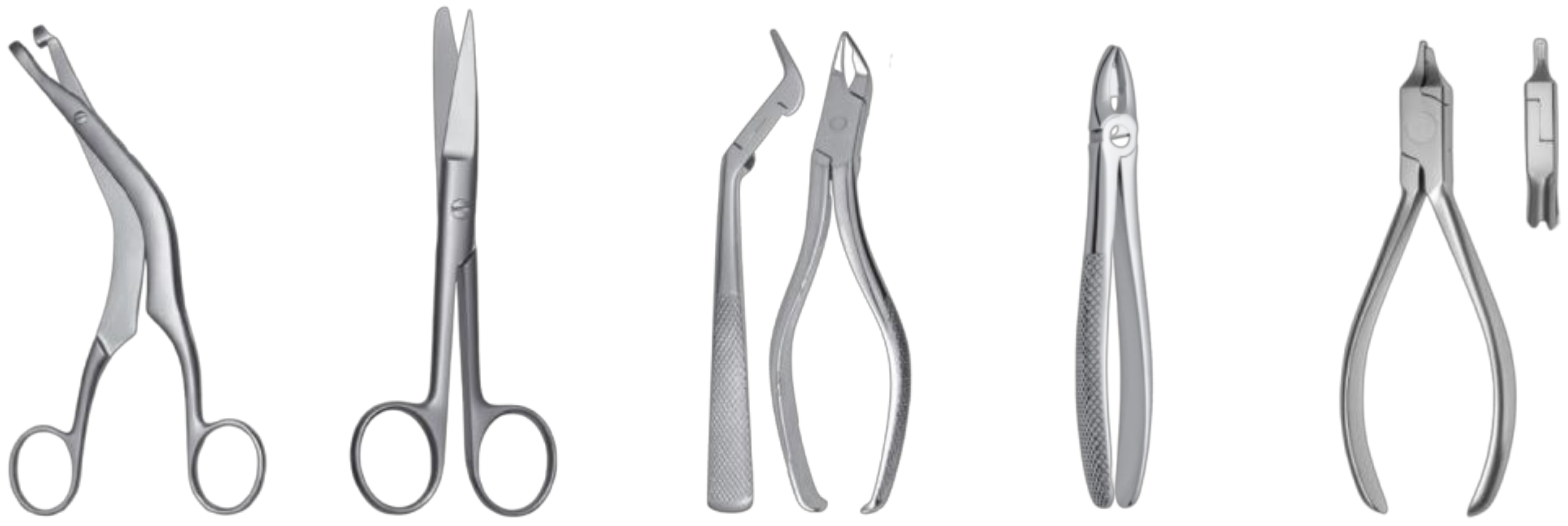
- variety of surgical tool shapes
- small production series
- large variation in shape and size deviations of the ground workpieces.
- I.
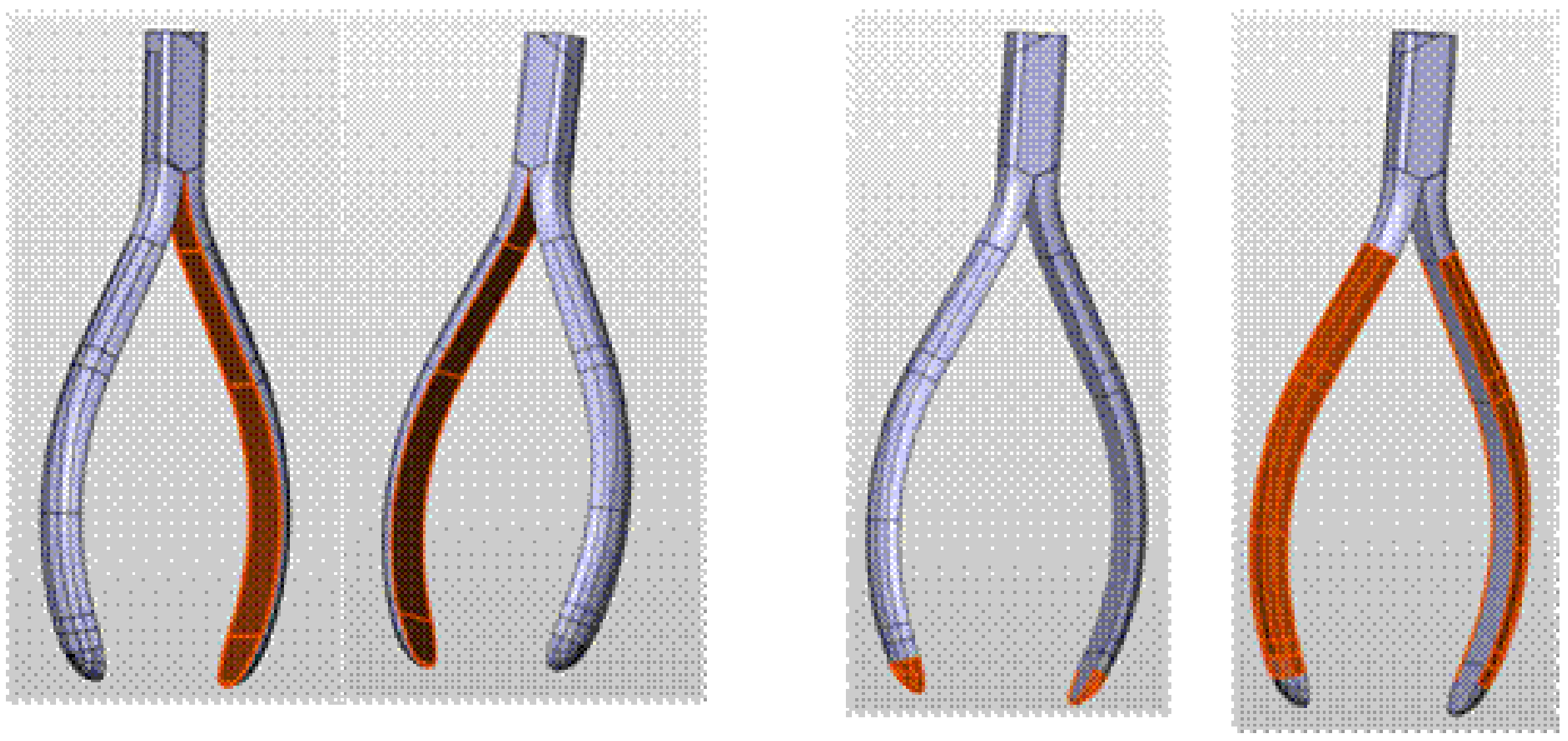
- Grinding the inner surface. The surface is curved along the axis of the workpiece, mirroring the profile of the forceps arm. In the direction perpendicular to the axis of the workpiece, the surface is flat.
- II.
- Grinding the tip of the arms that form elliptical paraboloid surfaces.
- III.
- Grinding an outer surface with curvature along the axis of the workpiece (such as an inner surface). The surface has the shape of a semi-oval in cross-section to the axis.
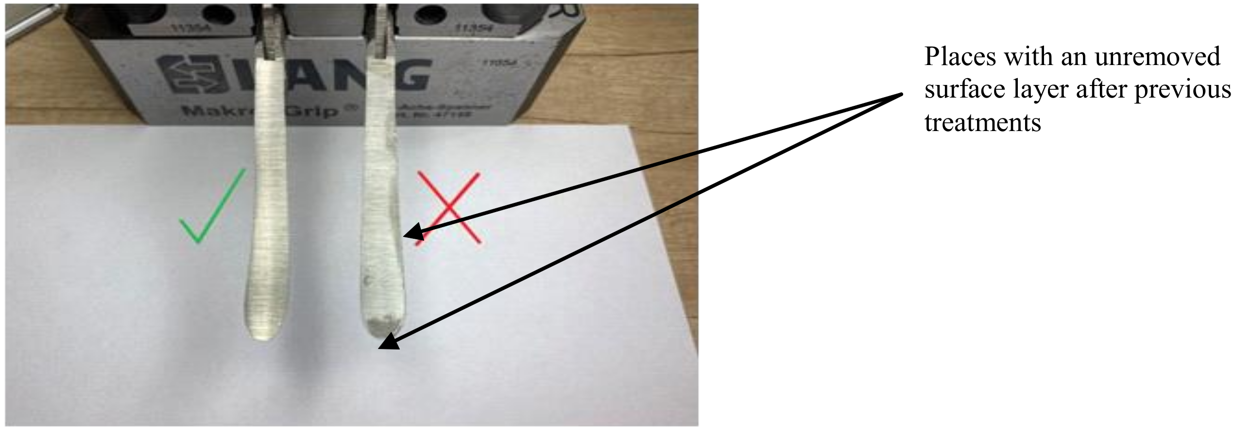
- surface cleanliness
- dimensional repeatability
- surface roughness
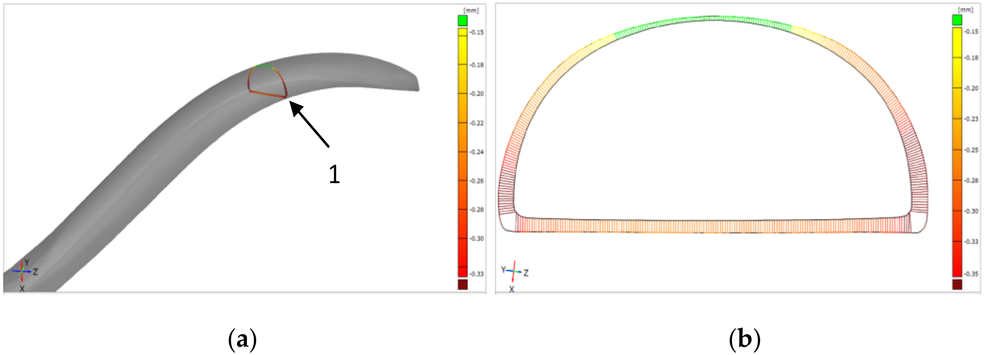
- shape accuracy
- surface condition


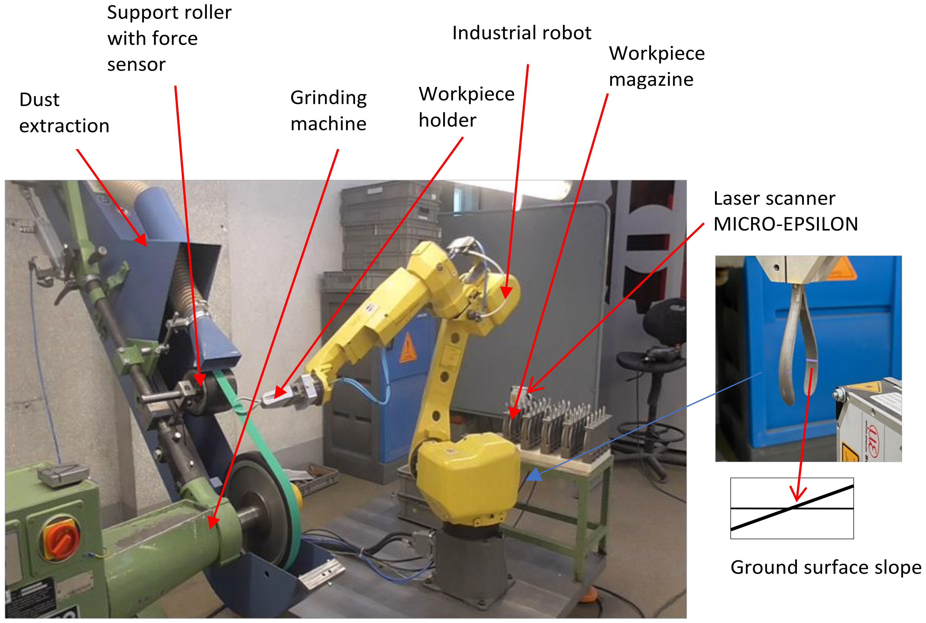
2.2. Research Stand for Robotic Belt Grinding
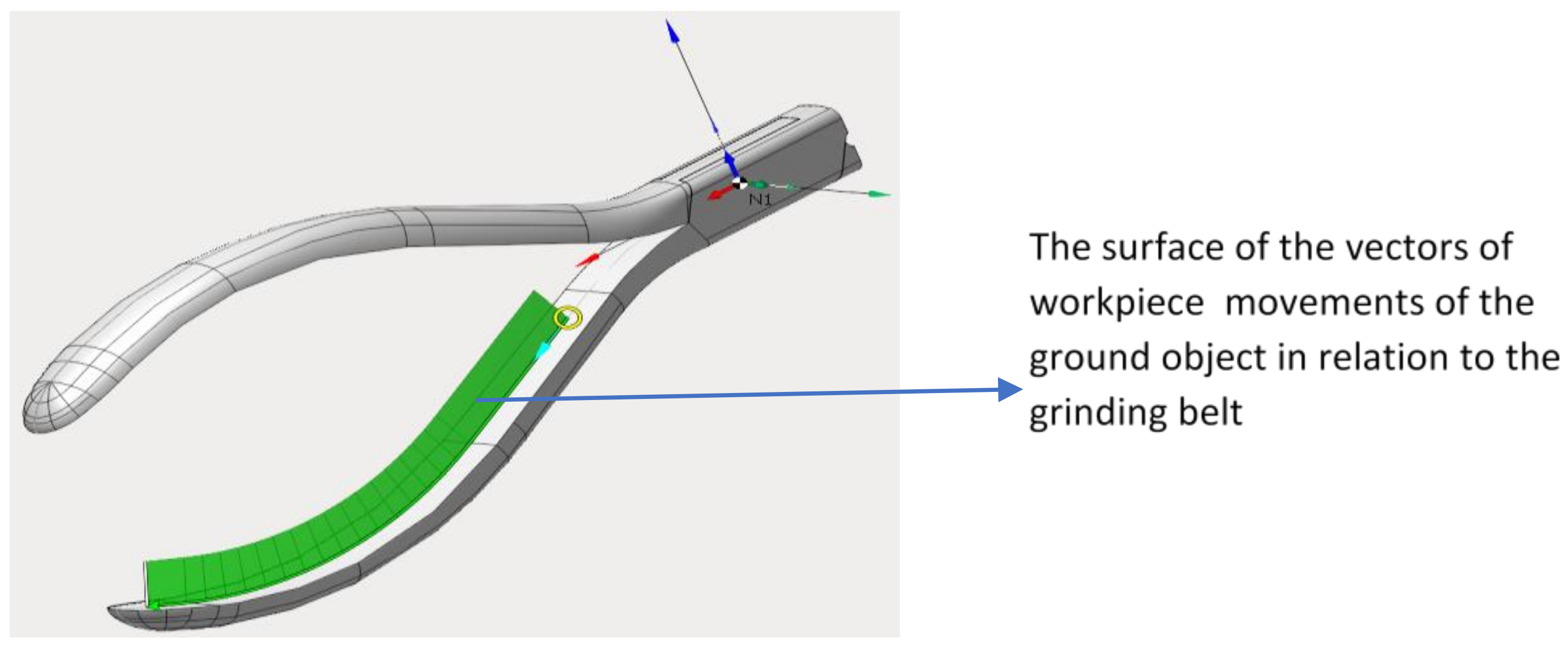
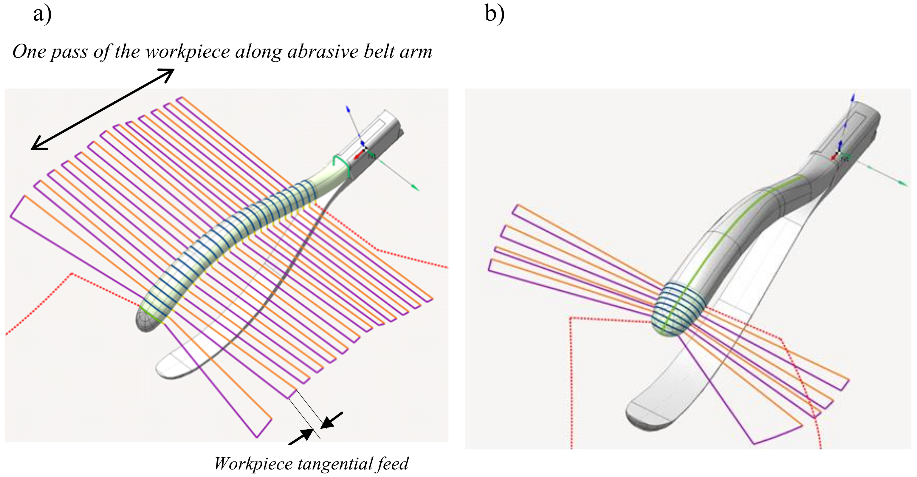
2.3. Machining Path Programming
- 3D model—enabling import and preparation of a geometrical model of a workpiece, including 2D drawing
- machining—used to create machining processes
- simulation—simulation of a machining program.
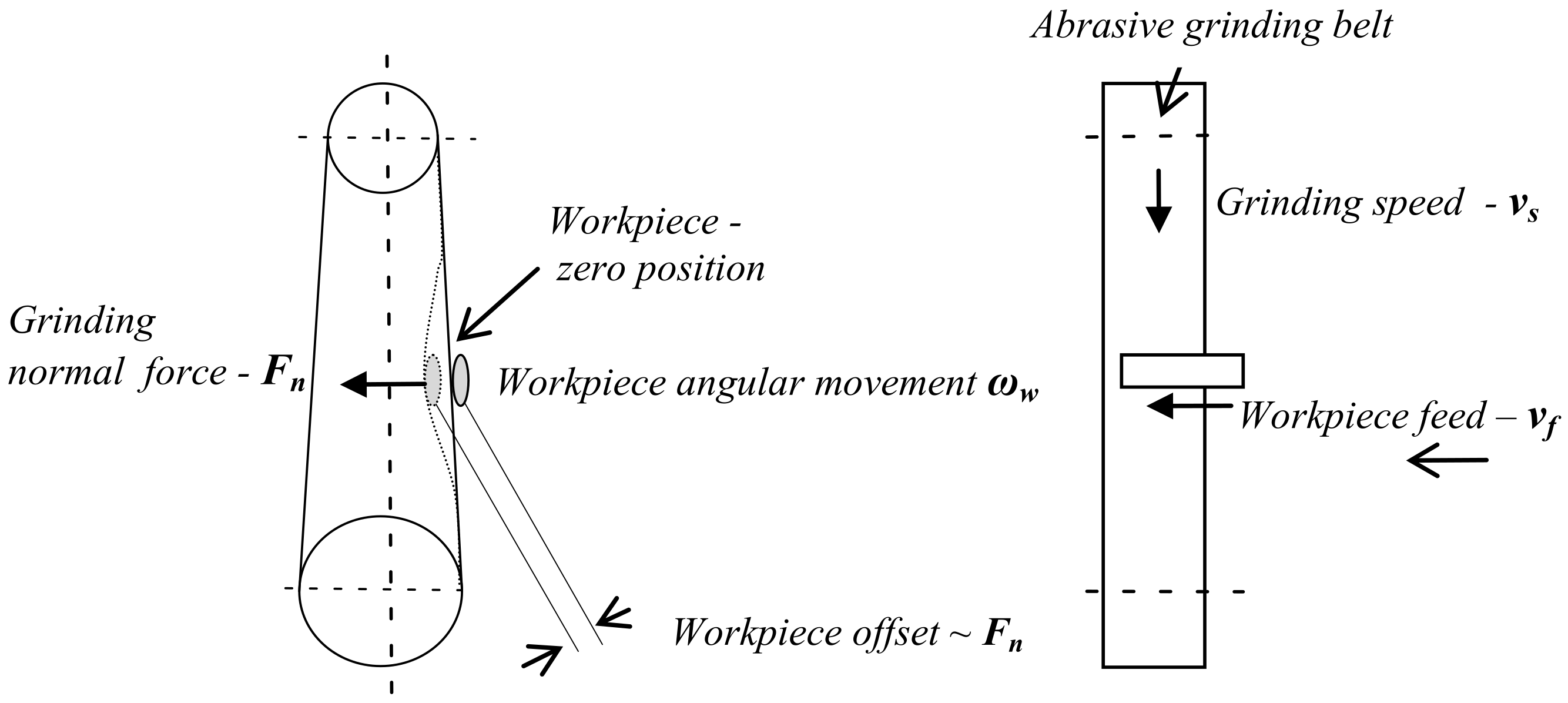
2.4. Grinding Parametres
- grinding speed—vs [m/s]
- grinding normal force—Fn [N] (the pressure of the workpiece on the abrasive belt)
- workpiece feed in the direction tangential to the abrasive belt—vf [mm/s]
- angular velocity of the workpiece rotation relative to the grinding belt—ωw [number of cycles/min]
- number of passes of the workpiece along the abrasive belt—nc
3. Results and Discussion
- Fn = 10 N
- vs = 26 m/s
- vf = 4 mm/s
4. Conclusions
Author Contributions
Funding
Institutional Review Board Statement
Informed Consent Statement
Data Availability Statement
Conflicts of Interest
References
- Wells, M.P. Surgical Instruments, 4th ed.; Elsevier: Amsterdam, The Netherlands, 2010. [Google Scholar]
- Ciurana, J. Designing, prototyping and manufacturing medical devices: An overview. Int. J. Comput. Integr. Manuf. 2014, 27, 901–918. [Google Scholar] [CrossRef]
- Mitchell, G.; Kevin, R.A.; Harvey, G.H.; Brijesh, S.G.; Joseph, L. 3D Printed Surgical Instruments: The Design and Fabrication Process. World J. Surgary 2017, 41, 314–319. [Google Scholar]
- Kondor, S. Personalized surgical instruments. J. Med. Devices ASME 2013, 7, 1–2. [Google Scholar] [CrossRef]
- Wang, T.; Zou, L.; Wan, Q.; Zhang, X.; Li, Y.; Huang, Y. A high-precision prediction model of surface roughness in abrasive belt flexible grinding of aero-engine blade. J. Manuf. Process. 2021, 66, 364–375. [Google Scholar]
- Wei, W.; Chao, Y. A path planning method for robotic belt surface grinding. Chin. J. Aeronaut. 2011, 24, 520–526. [Google Scholar]
- Ng, W.X.; Chan, H.K.; Teo, W.K.; Chen, I.M. Capturing the tacit knowledge of the skilled operator to program tool paths and tool orientations for robot belt grinding. Int. J. Adv. Manuf. Technol. 2017, 91, 1599–1618. [Google Scholar] [CrossRef]
- Zhu, D.; Fenga, X.; Xu, X.; Yang, Z.; Li, W.; Yan, S.; Ding, H. Robotic grinding of complex components: A step towards efficient and intelligent machining—Challenges, solutions, and applications. Robot. Comput. -Integr. Manuf. 2020, 65, 1–15. [Google Scholar] [CrossRef]
- Leali, F.; Vergnano, A.; Pini, F.; Pellicciari, M.; Berselli, G. A workcell calibration method for enhancing accuracy in robot machining of aerospace parts. Int. J. Adva. Manuf. Technol. 2014, 85, 47–55. [Google Scholar] [CrossRef]
- Ren, X.; Kuhlenkötter, B.; Müller, H. Simulation and verification of belt grinding with industrial robots. Int. J. Mach. Tools Manuf. 2006, 46, 708–716. [Google Scholar] [CrossRef]
- Klimchik, A.; Ambiehlb, A.; Garnierb, S.; Furetb, B.; Pashkevicha, A. Efficiency evaluation of robots in machining applications using industrial performance measure, Robot. Comput. Integr. Manuf. 2017, 48, 12–29. [Google Scholar] [CrossRef]
- Wu, S.; Kazerounian, K.; Gan, Z.; Sun, S. A simulation platform for optimal selection of robotic belt grinding system parameter. Int. J. Adva. Manuf. Technol. 2012, 64, 447–458. [Google Scholar] [CrossRef]
- Lin, Y.; Zhao, H.; Ding, H. Posture optimization methodology of 6R industrial robots for machining using performance evaluation indexes. Robot. Comput. Integr. Manuf. 2017, 48, 59–72. [Google Scholar] [CrossRef]
- Li, W.; Zhou, S.; Yan, J. A case study of blade inspection based on optical scanning method. Int. J. Prod. Res. 2015, 53, 2165–2178. [Google Scholar] [CrossRef]
- Slavkovic, N.; Milutinovic, D.; Glavonjic, M. A method for off-line compensation of cutting force-induced errors in robotic machining by tool path modification. Int. J. Adv. Manuf. Technol. 2013, 70, 2083–2096. [Google Scholar] [CrossRef]
- Song, Y.; Liang, W.; Yang, Y. A method for grinding removal control of a robot belt grinding system. J. Intell. Manuf. 2011, 23, 1903–1913. [Google Scholar] [CrossRef]
- Xu, X.; Zhu, D.; Zhang, H.; Yan, S.; Ding, H. Application of novel force control strategies to enhance robotic abrasive belt grinding quality of aero-engine blades. Chin. J. Aeronautics. 2019, 32, 2368–2382. [Google Scholar] [CrossRef]
- Huang, H.; Zhou, L.; Chen, X.; Gong, Z. Smart robotic system for 3d profile turbine vane airfoil repair. Int. J. Adv. Manuf. Technol. 2003, 21, 275–283. [Google Scholar] [CrossRef]
- Ng, W.X.; Chan, H.K.; Teo, W.K.; Chen, I.M. Programming robotic tool-path and tool-orientations for conformance grinding based on human demonstration. In Proceedings of the 2016 IEEE/RSJ International Conference on Intelligent Robots and Systems (IROS), Daejeon, Korea, 9–14 October 2016; IEEE: New York, NY, USA, 2016; pp. 1246–1253. [Google Scholar]
- Pais, L.; Umezawa, K.; Nakamura, Y. Learning robot skills through motion segmentation and constraints extraction. Computer Sci. 2013. [Google Scholar]
- Levine, S.; Wagener, N.; Abbeel, P. Learning contactrich manipulation skills with guided policy search. In Proceedings of the IEEE International Conference on Robotics & Automation, Seattle, WA, USA, 26–30 May 2015; pp. 156–163. [Google Scholar]
- Gao, X.; Ling, J.; Xiao, X.; Li, M. Learning forcerelevant skills from human demonstration. Complexity 2019, 2019, 1–11. [Google Scholar]
- Zhang, G.; Ni, F.; Liu, H.; Jiang, Z.; Yang, G.; Li, C. Learning impedance regulation skills for robot belt grinding from human demonstrations. Assembly Autom. 2021, 41. [Google Scholar]
- Zhao, P.; Shi, Y. Posture adaptive control of the flexible grinding head for blisk manufacturing. Int. J. Adv. Manuf. Technol. 2013, 9, 1989–2001. [Google Scholar] [CrossRef]
- Diao, S.; Chen, X.; Luo, J. Development and Experimental Evaluation of a 3D Vision System for Grinding Robot. Sensors 2019, 19, 1–20. [Google Scholar] [CrossRef] [PubMed]
- Zhu, D.; Xu, X.; Yang, Z.; Zhuang, K.; Yan, S.; Ding, H. Analysis and assessment of robotic belt grinding mechanisms by force modeling and force control experiments. Tribol. Int. 2018, 120, 93–98. [Google Scholar] [CrossRef]
- De Agustina, B.; Marín, M.M.; Teti, R.; Rubio, E.M. Analysis of Force Signals for the Estimation of Surface Roughness during Robot-Assisted Polishing. Materials 2018, 11, 2–8. [Google Scholar] [CrossRef] [PubMed]
- Zhang, T.; Su, J. Collision-free planning algorithm of motion path for the robot belt grinding system. Int. J. Adv. Robot. Syst. 2018, 15, 1–13. [Google Scholar] [CrossRef]
- Zou, L.; Liu, X.; Ren, X.; Huang, Y. Investigation of robotic abrasive belt grinding methods used for precision machining of aluminum blades. Int. J. Adv. Manuf. Technol. 2020, 108, 3267–3278. [Google Scholar] [CrossRef]
- Zhang, T.; Yu, Y.; Zou, Y. An Adaptive Sliding-Mode Iterative Constant-force Control Method for Robotic Belt Grinding Based on a One-Dimensional Force Sensor. Sensors 2019, 19, 1–26. [Google Scholar] [CrossRef]
- Pandiyan, V.; Caesarendra, W.; Tjahjowidodo, T.; Tan, H.H. In-process tool condition monitoring in compliant abrasive belt grinding process using support vector machine and genetic algorithm. J. Manuf. Process. 2018, 31, 199–213. [Google Scholar] [CrossRef]
- Hamdi, A.; Aliouane, T.; Bouzid, D. Technological Parameters of Belt Grinding Process of Hard Steel. Mech. Mech. Eng. 2017, 21, 843–853. [Google Scholar]
- Ren, X.; Cabaravdic, M.; Zhang, X.; Kuhlenkötter, B. A local process model for simulation of robotic belt grinding. Int. J. Mach. Tools Manuf. 2007, 47, 962–970. [Google Scholar] [CrossRef]
- Puthanangady, T.K.; Malkin, S. Experimental investigation of the superfinishing process. Wear 1995, 185, 173–182. [Google Scholar]
- Tong, X.; Wu, X.; Zhang, F.; Ma, G.; Zhang, Y.; Wen, B.; Tian, Y. Mechanism and Parameter Optimization in Grinding and Polishing of M300 Steel by an Elastic Abrasive. Materials 2019, 12, 1–19. [Google Scholar] [CrossRef]
- Pandiyan, V.; Caesarendra, W.; Tjahjowidodo, T.; Praveen, G. Predictive Modelling and Analysis of Process Parameters on Material Removal Characteristics in Abrasive Belt Grinding Process. Appl. Sci. 2017, 7, 1–17. [Google Scholar] [CrossRef]
- Jourani, A.; Dursapt, M.; Hamdi, H.; Rech, J.; Zahouani, H. Effect of the belt grinding on the surface texture: Modeling of the contact and abrasive wear. Wear 2005, 259, 1137–1143. [Google Scholar] [CrossRef]
- Xiao, G.; Song, K.; Liu, S.; Wu, Y.; Wang, W. Comprehensive investigation into the effects of relative grinding direction on abrasive belt grinding process. J. Manuf. Process. 2021, 62, 753–761. [Google Scholar] [CrossRef]
- Wang, Y.J.; Huang, Y.; Chen, Y.X.; Yang, Z. Model of an abrasive belt grinding surface removal contour and its application. Int. J. Adv. Manuf. Technol. 2016, 82, 2113–2122. [Google Scholar] [CrossRef]


| Robot | |
| Type | FANUC M-10iA/10M (high inertia version) |
| Controlled axes | 6 |
| Repeatability | 0.03 mm |
| Mechanical weight | 130 kg |
| Maximum load capacity at wrist | 10 kg |
| Motion range | 360o |
| Maximum speed | 360o/s |
| Grinder | |
| Type | Meatabo |
| Electric motor power | 3 kW |
| Factor | Factor Level | ||
|---|---|---|---|
| 1 | 2 | 3 | |
| Fn | 5 N | 10 N | 15 N |
| vs | 23 m/s | 26 m/s | 29 m/s |
| vt | 2 mm/s | 4 mm/s | 6 mm/s |
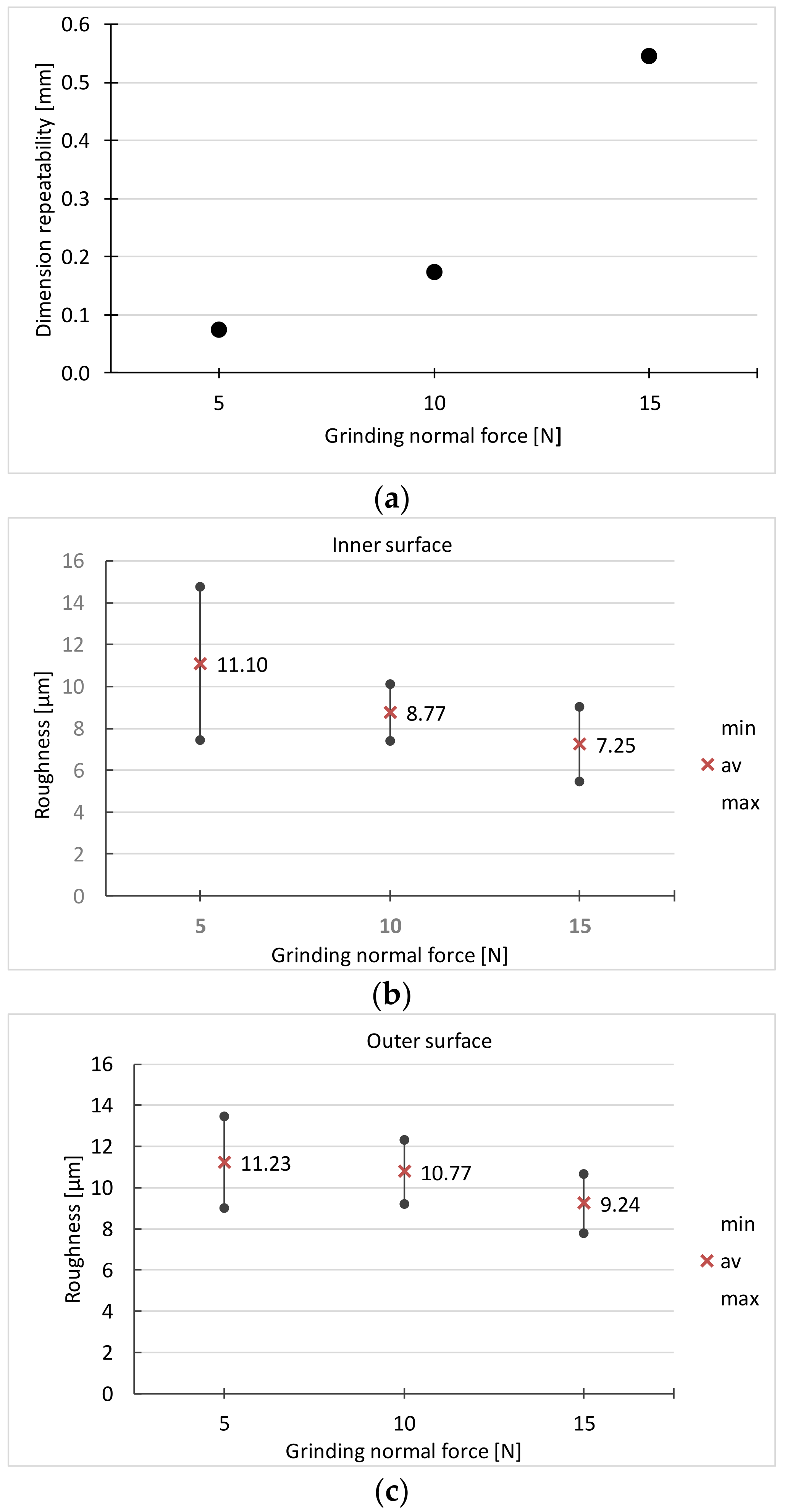
| Grinding Normal Force -Fn [N] | Surface Clean- Liness | Dimensional Repeatability [mm] | Roughness Inner Surface [µm] | Roughness Outer Surface [µm] | Surface Condition | ||
|---|---|---|---|---|---|---|---|
| Mean | Mean | Range | Mean | Range | |||
| 5 | 0 | 0.07 | 11.1 | 7.14 | 11.23 | 4.44 | 1 |
| 10 | 1 | 0.17 | 8.77 | 2.70 | 10.77 | 3.12 | 1 |
| 15 | 1 | 0.55 | 7.25 | 3.60 | 9.24 | 2.88 | 0 |
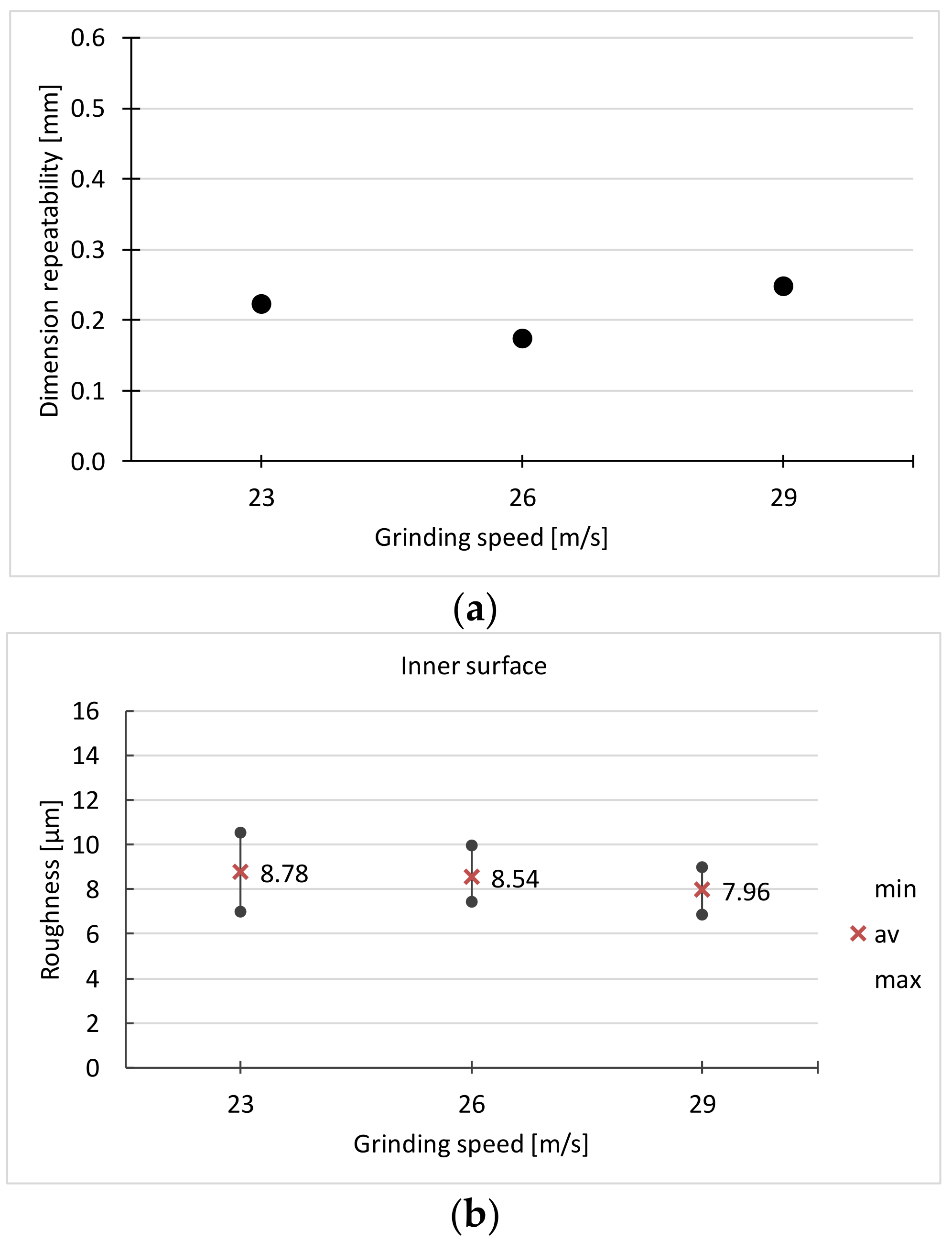
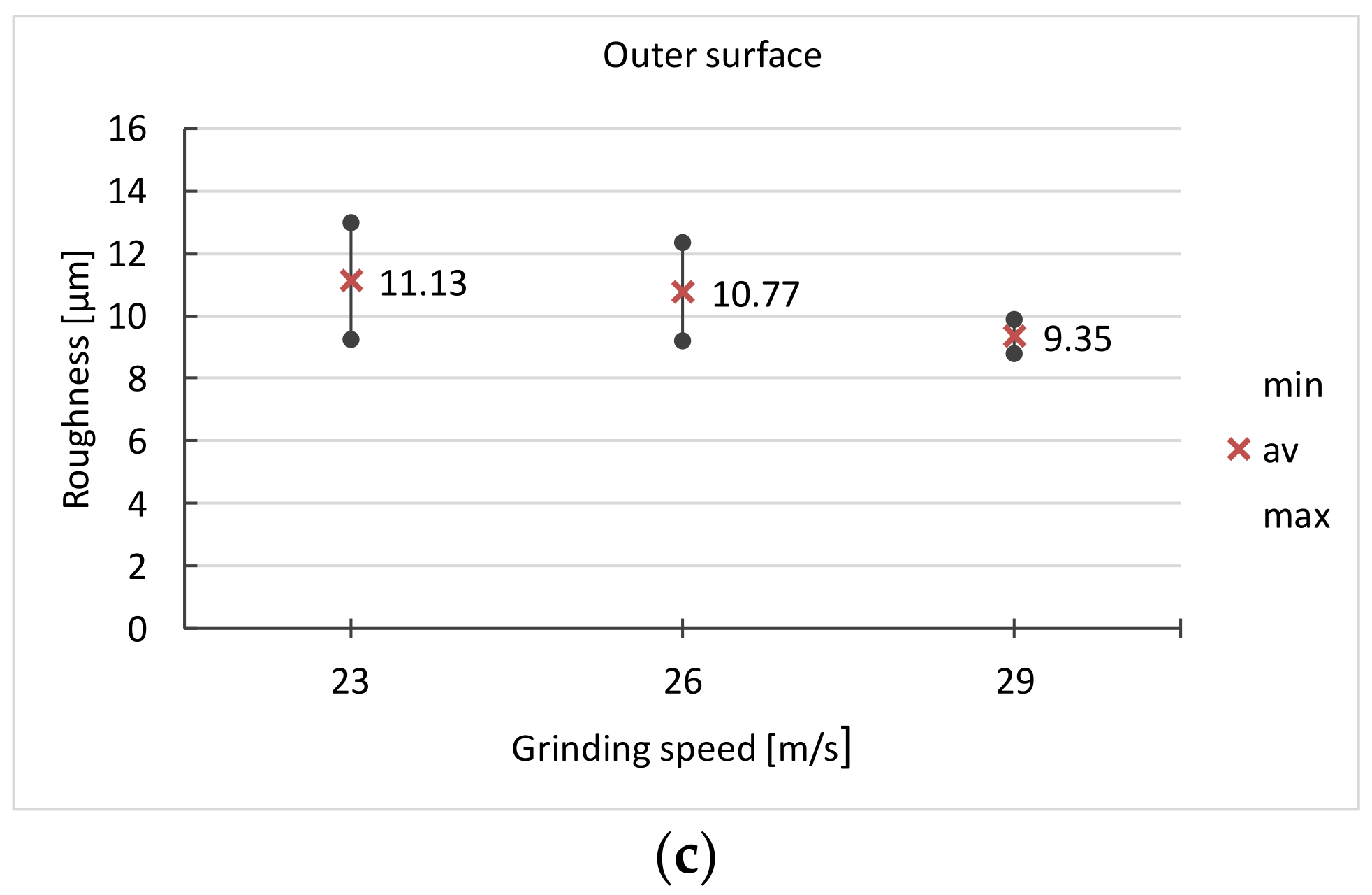
| Grinding Speed - vs [m/s] | Surface Clean- Liness | Dimensional Repeatability [mm] | Roughness Inner Surface [µm] | Roughness Outer Surface [µm] | Surface Condition | ||
|---|---|---|---|---|---|---|---|
| Mean | Mean | Range | Mean | Range | |||
| 23 | 1 | 0.22 | 8.78 | 3.70 | 11.13 | 3.74 | 1 |
| 26 | 1 | 0.17 | 8.54 | 2.70 | 10.77 | 3.12 | 1 |
| 29 | 0 | 0.25 | 7.96 | 1.76 | 9.35 | 1.07 | 0 |
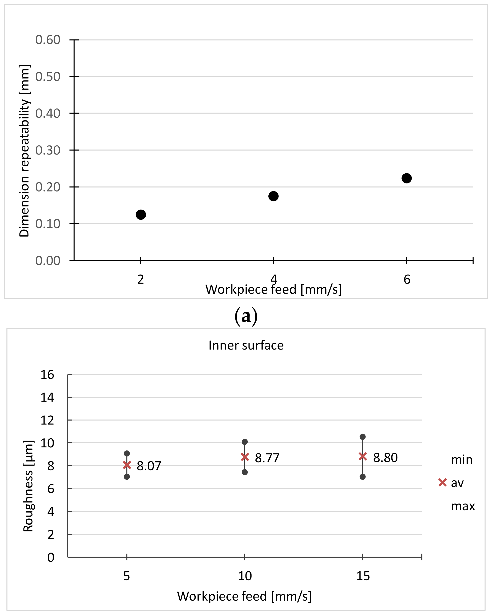
| Feed - vf [mm/s] | Surface Clean- Liness | Dimensional Repeatability [mm] | Roughness Inner Surface [µm] | Roughness Outer Surface [µm] | Surface Condition | ||
|---|---|---|---|---|---|---|---|
| Mean | Mean | Range | Mean | Range | |||
| 2 | 0 | 0.12 | 8.07 | 2.03 | 10.65 | 5.36 | 1 |
| 4 | 1 | 0.17 | 8.77 | 2.70 | 10.77 | 3.12 | 1 |
| 6 | 1 | 0.22 | 8.8 | 3.52 | 10.59 | 2.80 | 1 |
| Robotic | Manual | |
|---|---|---|
| Grinder | Metabo | Metabo |
| Grinding Belt | Klingspor LS312 J-Flex P150 | Hermes Ceramit CN 466 X-Flex 150 |
| Grinding speed—vs | 26 m/s | 26 m/s |
| Grinding normal force—Fn | 10 N | Determined by the grinder |
| Workpiece feed—vf | 4 mm/s | Determined by the grinder |
| Sample size | 50 | 50 |
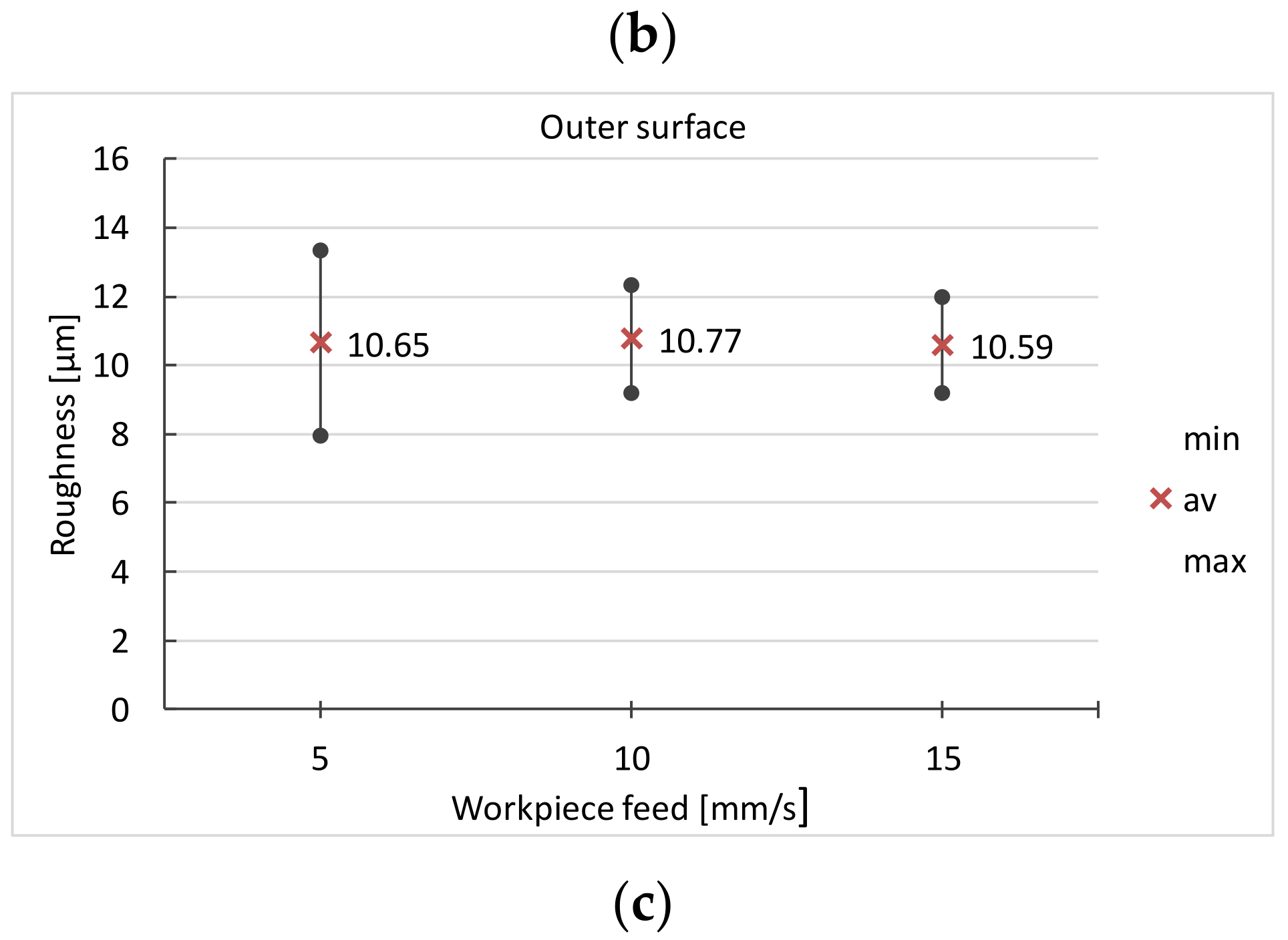
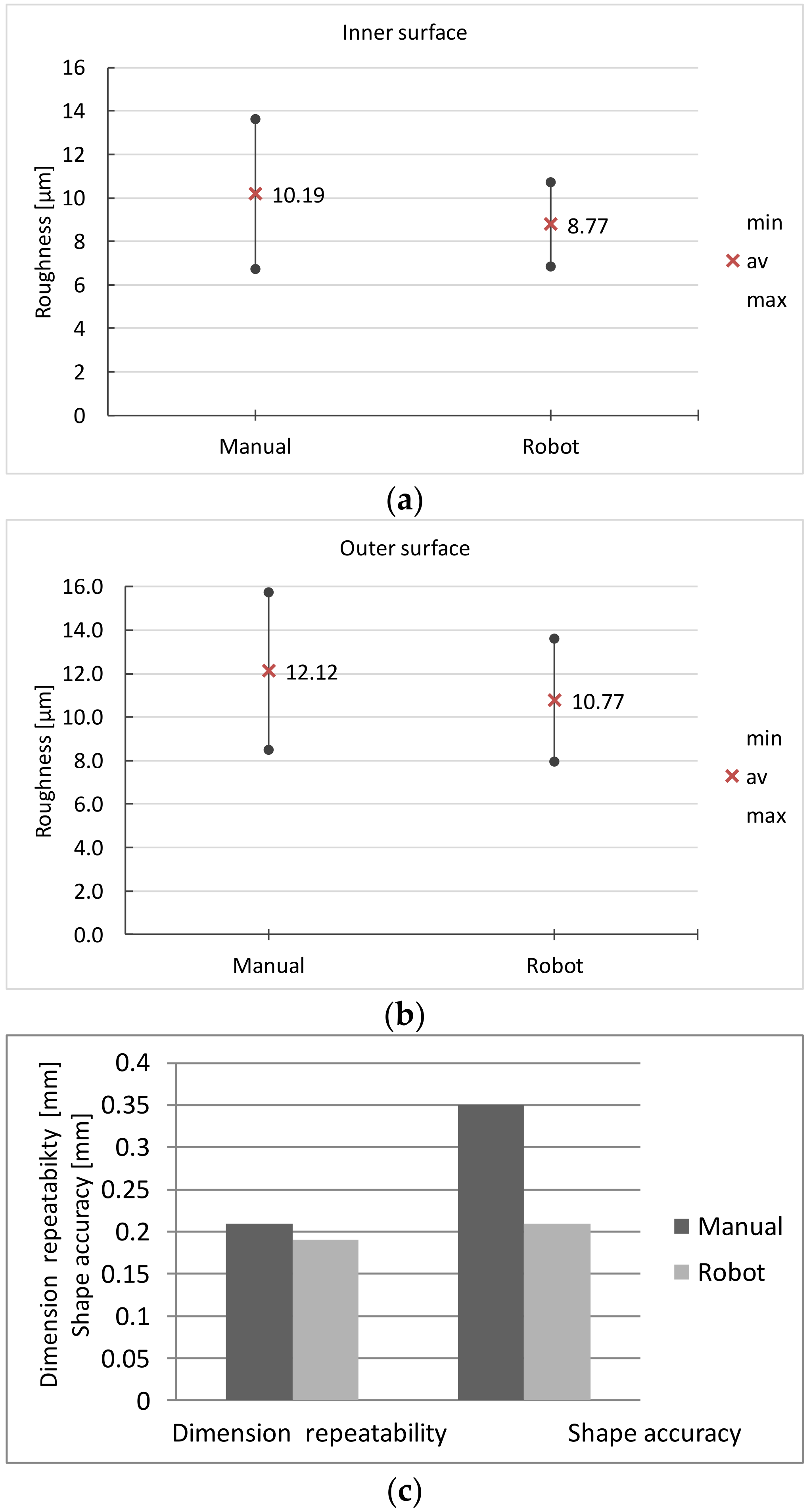
| Grinding Method | Surface Clean- Liness | Dimensional Repeatability [mm] | Roughness Inner Surface [µm] | Roughness Outer Surface [µm] | Surface Condi- tion | Shape Accuracy | ||
|---|---|---|---|---|---|---|---|---|
| Mean | Mean | Range | Mean | Range | Mean | |||
| Manual | 1 | 0.21 | 10.19 | 6.89 | 12.12 | 7.21 | 1 | 0.35 |
| With robot | 1 | 0.19 | 8.77 | 4.00 | 10.77 | 6.28 | 1 | 0.21 |
Disclaimer/Publisher’s Note: The statements, opinions and data contained in all publications are solely those of the individual author(s) and contributor(s) and not of MDPI and/or the editor(s). MDPI and/or the editor(s) disclaim responsibility for any injury to people or property resulting from any ideas, methods, instructions or products referred to in the content. |
© 2023 by the authors. Licensee MDPI, Basel, Switzerland. This article is an open access article distributed under the terms and conditions of the Creative Commons Attribution (CC BY) license (https://creativecommons.org/licenses/by/4.0/).
Share and Cite
Hamrol, A.; Hoffmann, M.; Lisek, M.; Bozek, J. The Quality of Surgical Instrument Surfaces Machined with Robotic Belt Grinding. Materials 2023, 16, 630. https://doi.org/10.3390/ma16020630
Hamrol A, Hoffmann M, Lisek M, Bozek J. The Quality of Surgical Instrument Surfaces Machined with Robotic Belt Grinding. Materials. 2023; 16(2):630. https://doi.org/10.3390/ma16020630
Chicago/Turabian StyleHamrol, Adam, Mateusz Hoffmann, Marcin Lisek, and Jedrzej Bozek. 2023. "The Quality of Surgical Instrument Surfaces Machined with Robotic Belt Grinding" Materials 16, no. 2: 630. https://doi.org/10.3390/ma16020630
APA StyleHamrol, A., Hoffmann, M., Lisek, M., & Bozek, J. (2023). The Quality of Surgical Instrument Surfaces Machined with Robotic Belt Grinding. Materials, 16(2), 630. https://doi.org/10.3390/ma16020630