
Current Trends in Wick Structure Construction in Loop Heat Pipes Applications: A Review


Abstract
:1. Introduction
2. Heat Transfer Using LHP
2.1. Application of LHPs
2.2. Theory of LHP
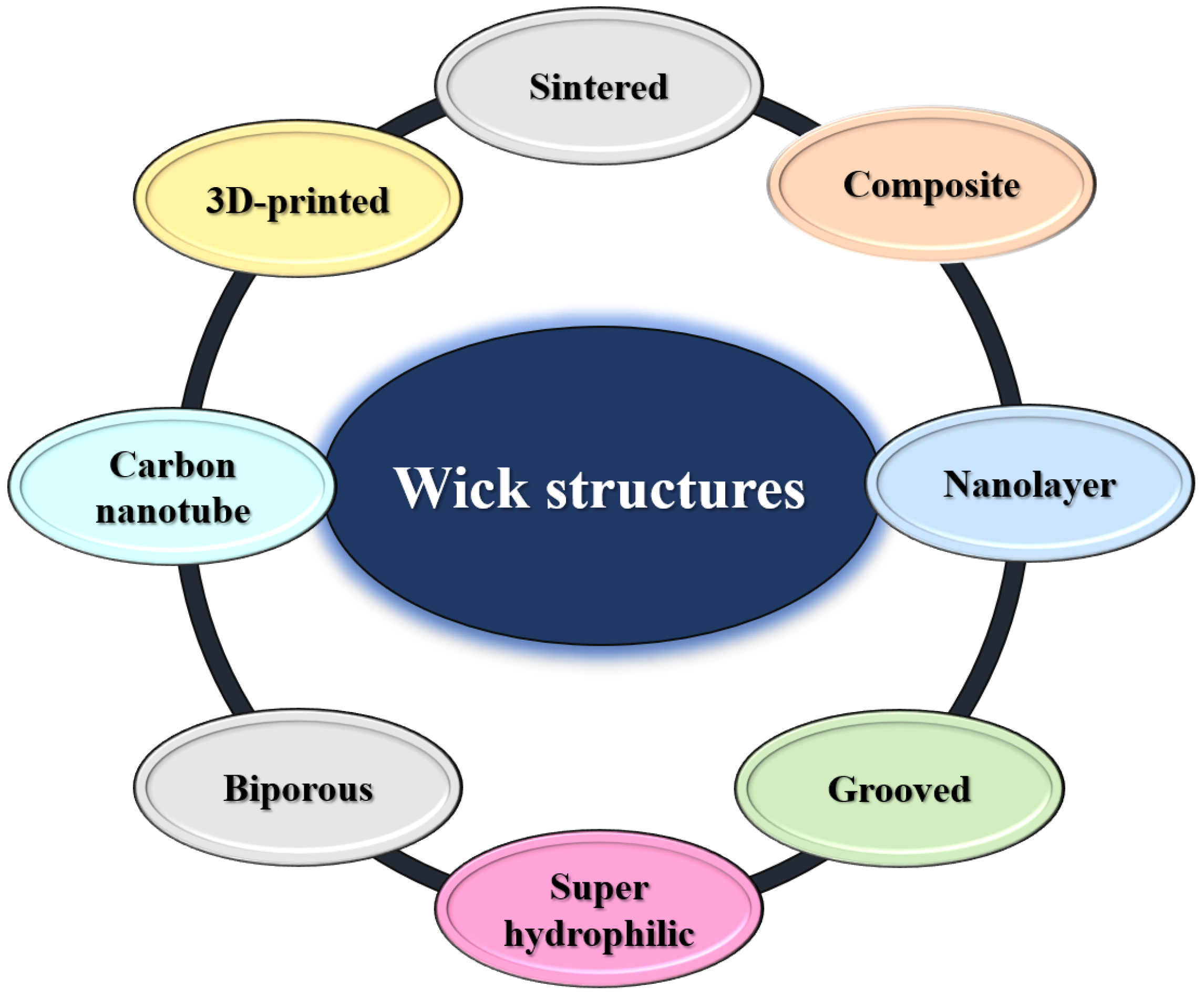
3. Wick Structures
3.1. Review of Thermal Conductivity
3.2. Heat Transfer Coefficient
3.3. Capillary Performance
4. Conclusions and Future Directions
Author Contributions
Funding
Institutional Review Board Statement
Informed Consent Statement
Data Availability Statement
Conflicts of Interest
References
- Launay, S.; Sartre, V.; Bonjour, J. Parametric analysis of loop heat pipe operation: A literature review. Int. J. Therm. Sci. 2007, 46, 621–636. [Google Scholar] [CrossRef]
- Rahman, M.L.; Sultan, R.A.; Islam, T.; Hasan, N.M.; Ali, M. An Experimental Investigation on the Effect of Fin in the Performance of Closed Loop Pulsating Heat Pipe (CLPHP). Procedia Eng. 2015, 105, 137–144. [Google Scholar] [CrossRef] [Green Version]
- Zhou, G.; Li, J.; Jia, Z. Power-saving exploration for high-end ultra-slim laptop computers with miniature loop heat pipe cooling module. Appl. Energy 2019, 239, 859–875. [Google Scholar] [CrossRef]
- Maydanik, Y. Loop heat pipes. Appl. Therm. Eng. 2005, 25, 635–657. [Google Scholar] [CrossRef]
- Maydanik, Y.; Chernysheva, M.; Pastukhov, V. Review: Loop heat pipes with flat evaporators. Appl. Therm. Eng. 2014, 67, 294–307. [Google Scholar] [CrossRef]
- Levêque, M.; Dutour, S.; Lluc, J.; Lavieille, P.; Miscevic, M.; Bertin, Y.; Mari, R.; Fourgeaud, L. Experimental study of a Capillary Pumped Loop assisted with a mechanical pump placed at the evaporator inlet. Appl. Therm. Eng. 2020, 169, 114850. [Google Scholar] [CrossRef]
- Richard, B.; Anderson, B.; Chen, C.; Crawmer, J.; Augustine, M. Development of a 3D Printed Loop Heat Pipe. In Proceedings of the 2019 35th Semiconductor Thermal Measurement, Modeling and Management Symposium (SEMI-THERM), San Jose, CA, USA, 18–22 March 2019. [Google Scholar]
- Vinod, R.; Basavarajappa, Y. Recent advances in loop heat pipe. Mater. Today Proc. 2021, 45, 389–391. [Google Scholar] [CrossRef]
- Shi, X.; Yin, B.; Chen, G.; Zhang, X.; Mei, X. Numerical study on two-phase flow and heat transfer characteristics of loop rotating heat pipe for cooling motorized spindle. Appl. Therm. Eng. 2021, 192, 116927. [Google Scholar] [CrossRef]
- Kang, Z.; Shou, D.; Fan, J. Numerical Study of a Novel Single-loop Pulsating Heat Pipe with Separating Walls within the Flow Channel. Appl. Therm. Eng. 2021, 196, 117246. [Google Scholar] [CrossRef]
- Wang, Z.; Yang, W. A review on loop heat pipe for use in solar water heating. Energy Build. 2014, 79, 143–154. [Google Scholar] [CrossRef]
- Vasta, S.; Palomba, V.; La Rosa, D.; Bonanno, A. Experimental assessment and numerical study of a pump-assisted loop heat pipe for high capacity thermal systems. Appl. Therm. Eng. 2020, 180, 115828. [Google Scholar] [CrossRef]
- Li, H.; Tang, Y.; Yuan, W.; Zhou, R. Numerical analysis on heat transfer of a complete anti-gravity loop-shaped heat pipe. Int. J. Heat Mass Transf. 2017, 109, 824–834. [Google Scholar] [CrossRef]
- Zhang, Y.; Liu, J.; Liu, L.; Jiang, H.; Luan, T. Numerical simulation and analysis of heat leakage reduction in loop heat pipe with carbon fiber capillary wick. Int. J. Therm. Sci. 2019, 146, 106100. [Google Scholar] [CrossRef]
- Bernagozzi, M.; Charmer, S.; Georgoulas, A.; Malavasi, I.; Miché, N.; Marengo, M. Lumped parameter network simulation of a Loop Heat Pipe for energy management systems in full electric vehicles. Appl. Therm. Eng. 2018, 141, 617–629. [Google Scholar] [CrossRef]
- Szymanski, P.; Law, R.; Glen RJ, M.; Reay, D.A. Recent Advances in Loop Heat Pipes with Flat Evaporator. Entropy 2021, 23, 1374. [Google Scholar] [CrossRef]
- Wu, S.-Y.; Zheng, X.-F.; Xiao, L. Phase change heat transfer characteristics of porous wick evaporator with bayonet tube and alkali metal as working fluid. Int. J. Therm. Sci. 2018, 126, 152–161. [Google Scholar] [CrossRef]
- Wang, D.; Wang, J.; Ding, S.; Chu, H. Study on evaporation heat transfer performance of composite porous wicks with spherical-dendritic powders based on orthogonal experiment. Int. J. Heat Mass Transf. 2020, 156, 119794. [Google Scholar] [CrossRef]
- Naemsai, T.; Kammuang-Lue, N.; Terdtoon, P.; Sakulchangsatjatai, P. Numerical model of heat transfer characteristics for sintered-grooved wick heat pipes under non-uniform heat loads. Appl. Therm. Eng. 2018, 148, 886–896. [Google Scholar] [CrossRef]
- Egbo, M.; Hwang, G. Phase-change heat transfer of bare surface evaporator with phase-separating wick in downward facing orientation. Int. J. Heat Mass Transf. 2021, 173, 121206. [Google Scholar] [CrossRef]
- Huang, S.; Wan, Z.; Zhang, X.; Yang, X.; Tang, Y. Evaluation of capillary performance of a stainless steel fiber–powder composite wick for stainless steel heat pipe. Appl. Therm. Eng. 2018, 148, 1224–1232. [Google Scholar] [CrossRef]
- Li, J.; Hong, F.; Xie, R.; Cheng, P. Pore scale simulation of evaporation in a porous wick of a loop heat pipe flat evaporator using Lattice Boltzmann method. Int. Commun. Heat Mass Transf. 2019, 102, 22–33. [Google Scholar] [CrossRef]
- Guangwen, H.; Wangyu, L.; Yuanqiang, L.; Yong, L.; Hanyin, C. Fabrication and capillary performance of a novel composite wick for ultra-thin heat pipes. Int. J. Heat Mass Transf. 2021, 176, 121467. [Google Scholar] [CrossRef]
- Xu, J.; Wang, Z.; Xu, H.; Zhang, L. Experimental research on the heat performance of a flat copper-water loop heat pipe with different inventories. Exp. Therm. Fluid Sci. 2017, 84, 110–119. [Google Scholar] [CrossRef]
- Li, S.; Jiang, Y.; Cai, W.; Zhang, H.; Li, F. Numerical study on condensation heat transfer and pressure drop characteristics of methane upward flow in a spiral pipe under sloshing condition. Int. J. Heat Mass Transf. 2018, 129, 310–325. [Google Scholar] [CrossRef]
- Qu, F.; Liu, H.; Jiang, C.; Guo, C.; Liu, Y.; Zhang, C. Nickel-ammonia loop heat pipe based on the molten salt pore forming startup and heat transfer failure characteristics of experimental study. Procedia Eng. 2017, 205, 3938–3945. [Google Scholar] [CrossRef]
- Deng, D.; Huang, Q.; Xie, Y.; Huang, X.; Chu, X. Thermal performance of composite porous vapor chambers with uniform radial grooves. Appl. Therm. Eng. 2017, 125, 1334–1344. [Google Scholar] [CrossRef]
- Xu, J.; Zhang, L.; Xu, H.; Zhong, J.; Xuan, J. Experimental investigation and visual observation of loop heat pipes with two-layer composite wicks. Int. J. Heat Mass Transf. 2014, 72, 378–387. [Google Scholar] [CrossRef]
- Yang, K.-S.; Tu, C.-W.; Zhang, W.-H.; Yeh, C.-T.; Wang, C.-C. A novel oxidized composite braided wires wick structure applicable for ultra-thin flattened heat pipes. Int. Commun. Heat Mass Transf. 2017, 88, 84–90. [Google Scholar] [CrossRef]
- Szymanski, P.; Mikielewicz, D. Additive Manufacturing as a Solution to Challenges Associated with Heat Pipe Production. Materials 2022, 15, 1609. [Google Scholar] [CrossRef]
- Arai, T.; Kawaji, M. Thermal performance and flow characteristics in additive manufactured polycarbonate pulsating heat pipes with Novec 7000. Appl. Therm. Eng. 2021, 197, 117273. [Google Scholar] [CrossRef]
- Odagiri, K.; Nagano, H. Heat transfer characteristics of flat evaporator loop heat pipe under high heat flux condition with different orientations. Appl. Therm. Eng. 2019, 153, 828–836. [Google Scholar] [CrossRef]
- Mitomi, M.; Nagano, H. Long-distance loop heat pipe for effective utilization of energy. Int. J. Heat Mass Transf. 2014, 77, 777–784. [Google Scholar] [CrossRef]
- Boo, J.; Kim, S.; Kang, Y. An Experimental Study on a Sodium Loop-type Heat Pipe for Thermal Transport from a High-temperature Solar Receiver. Energy Procedia 2015, 69, 608–617. [Google Scholar] [CrossRef] [Green Version]
- Qian, N.; Fu, Y.; Zhang, Y.; Chen, J.; Xu, J. Experimental investigation of thermal performance of the oscillating heat pipe for the grinding wheel. Int. J. Heat Mass Transf. 2019, 136, 911–923. [Google Scholar] [CrossRef]
- Zhao, J.; Wu, C.; Rao, Z. Numerical study on heat transfer enhancement of closed loop oscillating heat pipe through active incentive method. Int. Commun. Heat Mass Transf. 2020, 115, 104612. [Google Scholar] [CrossRef]
- Ramasamy, N.S.; Kumar, P.; Wangaskar, B.; Khandekar, S.; Maydanik, Y.F. Miniature ammonia loop heat pipe for terrestrial applications: Experiments and modeling. Int. J. Therm. Sci. 2018, 124, 263–278. [Google Scholar] [CrossRef]
- Xie, Y.; Zhou, Y.; Wen, D.; Wu, H.; Haritos, G.; Zhang, H. Experimental investigation on transient characteristics of a dual compensation chamber loop heat pipe subjected to acceleration forces. Appl. Therm. Eng. 2018, 130, 169–184. [Google Scholar] [CrossRef] [Green Version]
- Ahmad, H.; Kim, S.K.; Jung, S.Y. Analysis of thermally driven flow behaviors for two-turn closed-loop pulsating heat pipe in ambient conditions: An experimental approach. Int. J. Heat Mass Transf. 2019, 150, 119245. [Google Scholar] [CrossRef]
- Su, Q.; Chang, S.; Yang, C. Loop heat pipe-based solar thermal façade water heating system: A review of performance evaluation and enhancement. Sol. Energy 2021, 226, 319–347. [Google Scholar] [CrossRef]
- Zhao, J.; Qu, J.; Rao, Z. Thermal characteristic and analysis of closed loop oscillation heat pipe/phase change material (CLOHP/PCM) coupling module with different working media. Int. J. Heat Mass Transf. 2018, 126, 257–266. [Google Scholar] [CrossRef]
- Wermer, L.R.; Ward, M.J.; Simpson, J.D.; Zimmerman, R.A.; Stewart, J.A.; Jankowski, T.A.; Obrey, S.J.; Reid, R.S. A high capacity self-priming counter-gravity heat pipe: Modeling and experimental demonstration. Int. J. Heat Mass Transf. 2018, 125, 1369–1378. [Google Scholar] [CrossRef]
- El Achkar, G.; Lavieille, P.; Miscevic, M. Loop heat pipe and capillary pumped loop design: About heat transfer in the isolated bubbles zone of condensers. Appl. Therm. Eng. 2012, 33–34, 253–257. [Google Scholar] [CrossRef]
- Butler, D.; Ku, J.; Swanson, T. Loop Heat Pipes and Capillary Pumped Applications Perspective Loops-an applications perspective. AIP Conf. Proc. 2002, 49, 608. [Google Scholar]
- Wang, G.; Quan, Z.; Zhao, Y.; Wang, H. Effect of geometries on the heat transfer characteristics of flat-plate micro heat pipes. Appl. Therm. Eng. 2020, 180, 115796. [Google Scholar] [CrossRef]
- Singh, M. Capillarity enhancement of micro heat pipes using grooves with variable apex angle. Int. J. Therm. Sci. 2019, 150, 106239. [Google Scholar] [CrossRef]
- Lee, G.C.; Kim, S.H.; Kang, J.-Y.; Kim, M.H.; Jo, H. Leidenfrost temperature on porous wick surfaces: Decoupling the effects of the capillary wicking and thermal properties. Int. J. Heat Mass Transf. 2019, 145, 118809. [Google Scholar] [CrossRef]
- Yu, J.-J.; Li, Y.-R.; Ruan, D.-F.; Wu, C.-M. Aspect ratio and capillary ratio dependence of thermal-solutal capillary-buoyancy flow of a binary mixture in an annular pool. Int. J. Therm. Sci. 2018, 136, 347–356. [Google Scholar] [CrossRef]
- Jobli, M.I.; Yao, R.; Luo, Z.; Shahrestani, M.; Li, N.; Liu, H. Numerical and experimental studies of a Capillary-Tube embedded PCM component for improving indoor thermal environment. Appl. Therm. Eng. 2018, 148, 466–477. [Google Scholar] [CrossRef]
- Chernysheva, M.; Maydanik, Y. Effect of liquid filtration in a wick on thermal processes in a flat disk-shaped evaporator of a loop heat pipe. Int. J. Heat Mass Transf. 2016, 106, 222–231. [Google Scholar] [CrossRef]
- Putra, N.; Ariantara, B.; Pamungkas, R.A. Experimental investigation on performance of lithium-ion battery thermal management system using flat plate loop heat pipe for electric vehicle application. Appl. Therm. Eng. 2016, 99, 784–789. [Google Scholar] [CrossRef]
- Alizadeh, H.; Nazari, M.A.; Ghasempour, R.; Shafii, M.B.; Akbarzadeh, A. Numerical analysis of photovoltaic solar panel cooling by a flat plate closed-loop pulsating heat pipe. Sol. Energy 2020, 206, 455–463. [Google Scholar] [CrossRef]
- Zhou, G.; Li, J. Two-phase flow characteristics of a high performance loop heat pipe with flat evaporator under gravity. Int. J. Heat Mass Transf. 2018, 117, 1063–1074. [Google Scholar] [CrossRef]
- Song, H.; Zhi-Chun, L.; Jing, Z.; Chi, J.; Jin-Guo, Y.; Wei, L. Experimental study of an ammonia loop heat pipe with a flat plate evaporator. Int. J. Heat Mass Transf. 2016, 102, 1050–1055. [Google Scholar] [CrossRef]
- Li, H.; Sun, Y. Performance optimization and benefit analyses of a photovoltaic loop heat pipe/solar assisted heat pump water heating system. Renew. Energy 2018, 134, 1240–1247. [Google Scholar] [CrossRef]
- Li, H.; Zhou, B.; Tang, Y.; Zhou, R.; Liu, Z.; Xie, Y. Effect of working fluid on heat transfer performance of the anti-gravity loop-shaped heat pipe. Appl. Therm. Eng. 2015, 88, 391–397. [Google Scholar] [CrossRef]
- Yan, T.; Zhao, Y.-N.; Liang, J.; Liu, F. Investigation on optimal working fluid inventory of a cryogenic loop heat pipe. Int. J. Heat Mass Transf. 2013, 66, 334–337. [Google Scholar] [CrossRef]
- Guo, Y.; Lin, G.; He, J.; Zhang, H.; Miao, J.; Li, J. Supercritical startup strategy of cryogenic loop heat pipe with different working fluids. Appl. Therm. Eng. 2019, 155, 267–276. [Google Scholar] [CrossRef]
- Li, X.; Yao, D.; Zuo, K.; Xia, Y.; Yin, J.; Liang, H.; Zeng, Y.-P. Fabrication, microstructural characterization and gas permeability behavior of porous silicon nitride ceramics with controllable pore structures. J. Eur. Ceram. Soc. 2019, 39, 2855–2861. [Google Scholar] [CrossRef]
- Kim, J.; Kim, S.J. Experimental investigation on working fluid selection in a micro pulsating heat pipe. Energy Convers. Manag. 2020, 205, 112462. [Google Scholar] [CrossRef]
- Xu, G.; Xie, R.; Li, N.; Liu, C. Experimental Investigation of a Loop Heat Pipe With R245fa and R1234ze(E) as Working Fluids. J. Therm. Sci. Eng. Appl. 2021, 14, 041014. [Google Scholar] [CrossRef]
- Liu, C.; Xie, R.; Li, N.; Xu, G.; Dong, D. Visualization of compensator and evaporator of a loop heat pipe under different heating methods. Chem. Ind. Eng. Prog. 2021, 40, 2401–2415. [Google Scholar]
- Ling, W.; Zhou, W.; Yu, W.; Liu, R.; Hui, K. Thermal performance of loop heat pipes with smooth and rough porous copper fiber sintered sheets. Energy Convers. Manage 2017, 153, 323–334. [Google Scholar] [CrossRef] [Green Version]
- Jung, E.G.; Boo, J.H. Overshoot elimination of the evaporator wall temperature of a loop heat pipe through a bypass line. Appl. Therm. Eng. 2019, 165, 114594. [Google Scholar] [CrossRef]
- Krishnan, D.V.; Kumar, G.U.; Suresh, S.; Thansekhar, M.; Iqbal, U. Evaluating the scale effects of metal nanowire coatings on the thermal performance of miniature loop heat pipe. Appl. Therm. Eng. 2018, 133, 727–738. [Google Scholar] [CrossRef]
- Hao, T.; Ma, H.; Ma, X. Heat transfer performance of polytetrafluoroethylene oscillating heat pipe with water, ethanol, and acetone as working fluids. Int. J. Heat Mass Transf. 2018, 131, 109–120. [Google Scholar] [CrossRef]
- Odagiri, K.; Nagano, H. Investigation on liquid-vapor interface behavior in capillary evaporator for high heat flux loop heat pipe. Int. J. Therm. Sci. 2019, 140, 530–538. [Google Scholar] [CrossRef]
- Wang, H.; Lin, G.; Bai, L.; Fu, J.; Wen, D. Experimental study on an acetone-charged loop heat pipe with a nickel wick. Int. J. Therm. Sci. 2019, 146, 106104. [Google Scholar] [CrossRef]
- Anand, R.S.; Jawahar, C.P.; Solomon, A.B.; Benson, V.; Alan, K.A.; Nair, K.P.V.; Alan, V.A. Experimental studies on thermosyphon using low global warming potential refrigerant HFE7000 and nanorefrigerant HFE7000/Al2O3. J. Process. Mech. Eng. 2020, 235, 707–717. [Google Scholar] [CrossRef]
- Zhang, H.; Li, G.; Chen, L.; Man, G.; Miao, J.; Ren, X.; He, J.; Huo, Y. Development of Flat-Plate Loop Heat Pipes for Spacecraft Thermal Control. Microgravity Sci. Technol. 2019, 31, 435–443. [Google Scholar] [CrossRef]
- Zhang, Z.; Zhang, H.; Ma, Z.; Liu, Z.; Liu, W. Experimental study of heat transfer capacity for loop heat pipe with flat disk evaporator. Appl. Therm. Eng. 2020, 173, 115183. [Google Scholar] [CrossRef]
- Zhang, H.; Jiang, C.; Zhang, Z.; Liu, Z.; Luo, X.; Liu, W. A study on thermal performance of a pump-assisted loop heat pipe with ammonia as working fluid. Appl. Therm. Eng. 2020, 175, 115342. [Google Scholar] [CrossRef]
- Su, Q.; Chang, S.; Song, M.; Zhao, Y.; Dang, C. An experimental study on the heat transfer performance of a loop heat pipe system with ethanol-water mixture as working fluid for aircraft anti-icing. Int. J. Heat Mass Transf. 2019, 139, 280–292. [Google Scholar] [CrossRef]
- Guo, Y.; Lin, G.; Zhang, H.; Miao, J. Investigation on thermal behaviours of a methane charged cryogenic loop heat pipe. Energy 2018, 157, 516–525. [Google Scholar] [CrossRef]
- He, S.; Zhao, J.; Liu, Z.-C.; Tian, W.; Yang, J.-G.; Liu, W. Experimental investigation of loop heat pipe with a large squared evaporator for cooling electronics. Appl. Therm. Eng. 2018, 144, 383–391. [Google Scholar] [CrossRef]
- He, S.; Zhou, P.; Liu, W.; Liu, Z. Experimental study on thermal performance of loop heat pipe with a composite-material evaporator for cooling of electronics. Appl. Therm. Eng. 2020, 168, 114897. [Google Scholar] [CrossRef]
- Liu, L.; Yang, X.; Yuan, B.; Ji, X.; Wei, J. Experimental study on thermal performance of a loop heat pipe with a bypass line. Int. J. Heat Mass Transf. 2019, 147, 118996. [Google Scholar] [CrossRef]
- Tian, W.; He, S.; Liu, Z.; Liu, W. Experimental investigation of a miniature loop heat pipe with eccentric evaporator for cooling electronics. Appl. Therm. Eng. 2019, 159, 113982. [Google Scholar] [CrossRef]
- Wang, X.; Wei, J.; Deng, Y.; Wu, Z.; Sundén, B. Enhancement of loop heat pipe performance with the application of micro/nano hybrid structures. Int. J. Heat Mass Transf. 2018, 127, 1248–1263. [Google Scholar] [CrossRef]
- Francisco, K.J.M.; Lago, C.L.D. Improving thermal control of capillary electrophoresis with mass spectrometry and capacitively coupled contactless conductivity detection by using 3D printed cartridges. Talanta 2018, 185, 37–41. [Google Scholar] [CrossRef]
- Qin, X.; Cai, J.; Zhou, Y.; Kang, Z. Lattice Boltzmann simulation and fractal analysis of effective thermal conductivity in porous media. Appl. Therm. Eng. 2020, 180, 115562. [Google Scholar] [CrossRef]
- Wang, Y.; Ma, C.; Liu, Y.; Wang, D.; Liu, J. A model for the effective thermal conductivity of moist porous building materials based on fractal theory. Int. J. Heat Mass Transf. 2018, 125, 387–399. [Google Scholar] [CrossRef]
- Tang, H.; Weng, C.; Tang, Y.; Li, H.; Xu, T.; Fu, T. Thermal performance enhancement of an ultra-thin flattened heat pipe with multiple wick structure. Appl. Therm. Eng. 2020, 183, 116203. [Google Scholar] [CrossRef]
- Li, X.; Yao, D.; Zuo, K.; Xia, Y.; Zeng, Y.-P. Effects of pore structures on the capillary and thermal performance of porous silicon nitride as novel loop heat pipe wicks. Int. J. Heat Mass Transf. 2021, 169, 120985. [Google Scholar] [CrossRef]
- Liu, J.; Zhang, Y.; Feng, C.; Liu, L.; Luan, T. Study of copper chemical-plating modified polyacrylonitrile-based carbon fiber wick applied to compact loop heat pipe. Exp. Therm. Fluid Sci. 2018, 100, 104–113. [Google Scholar] [CrossRef]
- Yu, M.; Diallo, T.M.; Zhao, X.; Zhou, J.; Du, Z.; Ji, J.; Cheng, Y. Analytical study of impact of the wick’s fractal parameters on the heat transfer capacity of a novel micro-channel loop heat pipe. Energy 2018, 158, 746–759. [Google Scholar] [CrossRef]
- Maydanik, Y.; Pastukhov, V.; Chernysheva, M. Development and investigation of a loop heat pipe with a high heat-transfer capacity. Appl. Therm. Eng. 2018, 130, 1052–1061. [Google Scholar] [CrossRef]
- Boubaker, R.; Harmand, S.; Platel, V. Experimental study of the liquid/vapor phase change in a porous media of two-phase heat transfer devices. Appl. Therm. Eng. 2018, 143, 275–282. [Google Scholar] [CrossRef]
- Baek, Y.; Jung, E. Heat transfer performance of loop heat pipe for space vehicle thermal control under bypass line operation. Int. J. Heat Mass Transfer. 2022, 194, 123064. [Google Scholar] [CrossRef]
- Wang, Y.-Q.; Luo, J.-L.; Heng, Y.; Mo, D.-C.; Lyu, S.-S. Wettability modification to further enhance the pool boiling performance of the micro nano bi-porous copper surface structure. Int. J. Heat Mass Transf. 2018, 119, 333–342. [Google Scholar] [CrossRef]
- Giraudon, R.; Lips, S.; Fabrègue, D.; Gremillard, L.; Maire, E.; Sartre, V. Effect of the wick characteristics on the thermal behaviour of a LHP capillary evaporator. Int. J. Therm. Sci. 2018, 133, 22–31. [Google Scholar] [CrossRef]
- Wen, R.; Xu, S.; Lee, Y.-C.; Yang, R. Capillary-driven liquid film boiling heat transfer on hybrid mesh wicking structures. Nano Energy 2018, 51, 373–382. [Google Scholar] [CrossRef]
- Qu, J.; Sun, Q.; Wang, H.; Zhang, D.; Yuan, J. Performance characteristics of flat-plate oscillating heat pipe with porous metal-foam wicks. Int. J. Heat Mass Transf. 2019, 137, 20–30. [Google Scholar] [CrossRef]
- Jo, H.S.; An, S.; Nguyen, X.H.; Kim, Y.I.; Bang, B.-H.; James, S.C.; Choi, J.; Yoon, S.S. Modifying capillary pressure and boiling regime of micro-porous wicks textured with graphene oxide. Appl. Therm. Eng. 2017, 128, 1605–1610. [Google Scholar] [CrossRef]
- Li, J.; Zhang, M. Biporous nanocarbon foams and the effect of the structure on the capillary performance. Prog. Nat. Sci. 2020, 30, 360–365. [Google Scholar] [CrossRef]
- Young, T. An essay on the cohesion of fluids. Abstr. Pap. Print. Philos. Trans. R. Soc. Lond. 1832, 1, 171–172. [Google Scholar] [CrossRef] [Green Version]
- Zhang, Z.; Zhao, R.; Liu, Z.; Liu, W. Application of biporous wick in flat-plate loop heat pipe with long heat transfer distance. Appl. Therm. Eng. 2020, 184, 116283. [Google Scholar] [CrossRef]
- Li, Q.; Lan, Z.; Chun, J.; Lian, S.; Wen, R.; Ma, X. Fabrication and capillary characterization of multi-scale micro-grooved wicks with sintered copper powder. Int. Commun. Heat Mass Transf. 2021, 121, 105123. [Google Scholar] [CrossRef]
- He, S.; Zhou, P.; Ma, Z.; Deng, W.; Zhang, H.; Chi, Z.; Liu, W.; Liu, Z. Experimental study on transient performance of the loop heat pipe with a pouring porous wick. Appl. Therm. Eng. 2019, 164, 114450. [Google Scholar] [CrossRef]
- Giraudon, R.; Lips, S.; Fabrègue, D.; Gremillard, L.; Maire, E.; Sartre, V. Effect of surface properties of capillary structures on the thermal behaviour of a LHP flat disk-shaped evaporator. Int. J. Therm. Sci. 2019, 142, 163–175. [Google Scholar] [CrossRef]
- Ling, W.; Zhou, W.; Yu, W.; Chu, X. Capillary pumping performance of porous copper fiber sintered wicks for loop heat pipes. Appl. Therm. Eng. 2018, 129, 1582–1594. [Google Scholar] [CrossRef]
- Zhang, X.; Liu, Y.; Wen, X.; Li, C.; Hu, X. Low-grade waste heat driven desalination with an open loop heat pipe. Energy 2018, 163, 221–228. [Google Scholar] [CrossRef]
- Feng, C.; Yugeswaran, S.; Chandra, S. Capillary rise of liquids in thermally sprayed porous copper wicks. Exp. Therm. Fluid Sci. 2018, 98, 206–216. [Google Scholar] [CrossRef]
- Zhong, G.; Ding, X.; Tang, Y.; Yu, S.; Chen, G.; Tang, H.; Li, Z. Various orientations research on thermal performance of novel multi-branch heat pipes with different sintered wicks. Energy Convers. Manag. 2018, 166, 512–521. [Google Scholar] [CrossRef]
- Zhang, S.; Chen, C.; Chen, G.; Sun, Y.; Tang, Y.; Wang, Z. Capillary performance characterization of porous sintered stainless steel powder wicks for stainless steel heat pipes. Int. Commun. Heat Mass Transf. 2020, 116, 104702. [Google Scholar] [CrossRef]
- Mathews, A.J.; Ranjan, S.; Inbaoli, A.; Kumar, C.S.; Jayaraj, S. Optimization of the sintering parameters of a biporous copper-nickel composite wick for loop heat pipes. Mater. Today Proc. 2020, 46, 9297–9302. [Google Scholar] [CrossRef]
- Lee, S.; Lee, J.; Hwang, H.; Yeo, T.; Lee, H.; Choi, W. Layer-by-layer assembled carbon nanotube-polyethyleneimine coatings inside copper-sintered heat pipes for enhanced thermal performance. Carbon 2018, 140, 521–532. [Google Scholar] [CrossRef]
- Zeng, J.; Zhang, S.; Chen, G.; Lin, L.; Sun, Y.; Chuai, L.; Yuan, W. Experimental investigation on thermal performance of aluminum vapor chamber using micro-grooved wick with reentrant cavity array. Appl. Therm. Eng. 2017, 130, 185–194. [Google Scholar] [CrossRef]
- Zhou, W.; Li, Y.; Chen, Z.; Deng, L.; Gan, Y. A novel ultra-thin flattened heat pipe with biporous spiral woven mesh wick for cooling electronic devices. Energy Convers. Manag. 2018, 180, 769–783. [Google Scholar] [CrossRef]
- Li, Z. Design and preliminary experiments of a novel heat pipe using a spiral coil as capillary wick. Int. J. Heat Mass Transf. 2018, 126, 1240–1251. [Google Scholar] [CrossRef]
- Xin, F.; Ma, T.; Wang, Q. Thermal performance analysis of flat heat pipe with graded mini-grooves wick. Appl. Energy 2018, 228, 2129–2139. [Google Scholar] [CrossRef]
- Wong, S.-C.; Liao, W.-S. Visualization experiments on flat-plate heat pipes with composite mesh-groove wick at different tilt angles. Int. J. Heat Mass Transf. 2018, 123, 839–847. [Google Scholar] [CrossRef]
- Jiang, X.; Tang, H.; Liu, Y.; Lian, L. The heat transfer capacity of multi-layer wick heat pipe tested in anti-gravity orientations. Appl. Therm. Eng. 2021, 200, 117611. [Google Scholar] [CrossRef]
- Lee, D.; Byon, C. Fabrication and characterization of pure-metal-based submillimeter-thick flexible flat heat pipe with innovative wick structures. Int. J. Heat Mass Transf. 2018, 122, 306–314. [Google Scholar] [CrossRef]
- Zhou, W.; Li, Y.; Chen, Z.; Deng, L.; Li, B. Experimental study on the heat transfer performance of ultra-thin flattened heat pipe with hybrid spiral woven mesh wick structure. Appl. Therm. Eng. 2020, 170, 115009. [Google Scholar] [CrossRef]
- Xu, J.; Wang, D.; Hu, Z.; Zhang, L.; Ye, L.; Zhou, Y. Effect of the working fluid transportation in the copper composite wick on the evaporation efficiency of a flat loop heat pipe. Appl. Therm. Eng. 2020, 178, 115515. [Google Scholar] [CrossRef]
- Zhu, K.; Li, X.; Li, H.; Chen, X.; Wang, Y. Experimental and theoretical study of a novel loop heat pipe. Appl. Therm. Eng. 2018, 130, 354–362. [Google Scholar] [CrossRef]
- Nasersharifi, Y.; Kaviany, M.; Hwang, G. Pool-boiling enhancement using multilevel modulated wick. Appl. Therm. Eng. 2018, 137, 268–276. [Google Scholar] [CrossRef] [Green Version]
- Sudhakar, S.; Weibel, J.A.; Zhou, F.; Dede, E.M.; Garimella, S.V. Area-scalable high-heat-flux dissipation at low thermal resistance using a capillary-fed two-layer evaporator wick. Int. J. Heat Mass Transf. 2019, 135, 1346–1356. [Google Scholar] [CrossRef] [Green Version]
- Li, Y.; Zhou, W.; Li, Z.; Chen, Z.; Gan, Y. Experimental analysis of thin vapor chamber with composite wick structure under different cooling conditions. Appl. Therm. Eng. 2019, 156, 471–484. [Google Scholar] [CrossRef]
- Sudhakar, S.; Weibel, J.A.; Garimella, S.V. Experimental investigation of boiling regimes in a capillary-fed two-layer evaporator wick. Int. J. Heat Mass Transf. 2019, 135, 1335–1345. [Google Scholar] [CrossRef] [Green Version]
- Wang, D.; Wang, J.; Bao, X.; Chen, G.; Chu, H. Evaporation heat transfer characteristics of composite porous wick with spherical-dendritic powders. Appl. Therm. Eng. 2019, 152, 825–834. [Google Scholar] [CrossRef]
- Li, H.; Fu, S.; Li, G.; Fu, T.; Zhou, R.; Tang, Y.; Tang, B.; Deng, Y.; Zhou, G. Effect of fabrication parameters on capillary pumping performance of multi-scale composite porous wicks for loop heat pipe. Appl. Therm. Eng. 2018, 143, 621–629. [Google Scholar] [CrossRef]
- Xin, G.; Zhang, P.; Chen, Y.; Cheng, L.; Huang, T.; Yin, H. Development of composite wicks having different thermal conductivities for loop heat pipes. Appl. Therm. Eng. 2018, 136, 229–236. [Google Scholar] [CrossRef]
- Li, H.; Fang, X.; Li, G.; Zhou, G.; Tang, Y. Investigation on fabrication and capillary performance of multi-scale composite porous wick made by alloying-dealloying method. Int. J. Heat Mass Transf. 2018, 127, 145–153. [Google Scholar] [CrossRef]
- Cui, Z.; Jia, L.; Wang, Z.; Dang, C.; Yin, L. Thermal performance of an ultra-thin flat heat pipe with striped super-hydrophilic wick structure. Appl. Therm. Eng. 2022, 208, 118249. [Google Scholar] [CrossRef]
- Hu, Z.; Wang, D.; Xu, J.; Zhang, L. Development of a loop heat pipe with the 3D printed stainless steel wick in the application of thermal management. Int. J. Heat Mass Transf. 2020, 161, 120258. [Google Scholar] [CrossRef]
- Jafari, D.; Wits, W.W.; Geurts, B.J. Metal 3D-printed wick structures for heat pipe application: Capillary performance analysis. Appl. Therm. Eng. 2018, 143, 403–414. [Google Scholar] [CrossRef]
- Ren, H.; Li, W.; Ning, J. Effect of temperature on the impact ignition behavior of the aluminum/polytetrafluoroethylene reactive material under multiple pulse loading. Mater. Des. 2020, 189, 108522. [Google Scholar] [CrossRef]
- Christy, J.V.; Mourad, A.-H.I.; Tiwari, S.; Sherif, M.M. Influence of Graphite and Polytetrafluoroethylene Dispersions on Mechanical, Abrasive, and Erosive Wear Performance of Thermal Spray Coatings. Surf. Interfaces 2020, 21, 100737. [Google Scholar] [CrossRef]
- Parthasarathi, N.; Borah, U.; Davinci, M.A.; Albert, S. Effect of temperature in axial compression testing of Polytetrafluoroethylene employed in lamp holders of prototype fast breeder periscope. Mater. Today Proc. 2020, 39, 478–483. [Google Scholar] [CrossRef]
- Babu, E.; Reddappa, H.; Reddy, G.G. Effect of Filling Ratio on Thermal Performance of Closed Loop Pulsating Heat Pipe. Mater. Today Proc. 2018, 5, 22229–22236. [Google Scholar] [CrossRef]
- Maydanik, Y.; Vershinin, S.; Chernysheva, M. Investigation of thermal characteristics of a loop heat pipe in a wide range of external conditions. Int. J. Heat Mass Transf. 2019, 147, 118967. [Google Scholar] [CrossRef]


| Working Fluid | Power (W) | Property | Effect | Ref. |
|---|---|---|---|---|
| Water | 20–160 | LHP through a bypass line |
| [64] |
| Water | 20–580 | Copper nanowire coating |
| [65] |
| Water | 50–300 | Oscillating LHP |
| [66] |
| Acetone | 60–240 | Flat evaporator |
| [67] |
| Acetone | N/A 1 | LHP with a nickel wick |
| [68] |
| Ethanol | 25–180 | Miniature LHP with flat evaporator |
| [69] |
| Ammonia | 6–50 | Stainless steel flat LHP |
| [70] |
| Ammonia | 2.5–180 | Stainless steel LHP with flat disk evaporator |
| [71] |
| Ammonia | 5–370 | Stainless steel LHP |
| [72] |
| Ethanol-Water | 100–300 | Stainless steel-nickel LHP |
| [73] |
| Methane | 2–10 | Cryogenic LHP |
| [74] |
| R245fa | 10–160 | Evaporator with a strengthened ribbed plate |
| [75] |
| R245fa | 10–140 | LHP with a composite-material evaporator |
| [76] |
| Methanol | N/A | LHP with a bypass line |
| [77] |
| Methanol | 2–60 | Bi-porous nickel wick |
| [78] |
| Methanol | 30–170 | Micro/nano-hybrid structures |
| [79] |
| Wick | Working Fluid | Power (W) | Thermal Resistance | Main Findings | Refs. |
|---|---|---|---|---|---|
| Cement-Pouring porous wick | Methanol | 10–80 | 0.2 (W/K) |
| [99] |
| Porous cylindrical wick | Pentane | 10–100 | N/A |
| [100] |
| Porous copper fiber sintered wicks (PCFSWs) | Water- Ethanol | N/A | N/A |
| [101] |
| Porous NiO wick | N/A | 20–160 | N/A |
| [102] |
| Microstructure of porous copper wick | N/A | N/A | N/A |
| [103] |
| Sintered copper powder wick | Water | 10–100 | 0.05 (°C/W) |
| [104] |
| Sintered porous wicks using stainless steel | Ethanol | N/A | N/A |
| [105] |
| Bi-porous Composite wick-Wick consists of 3 layers | N/A | N/A | N/A |
| [106] |
| Biporous structure of multi-walled carbon nanotube (MWCNT)- polyethyleneimine shells | Water | 20–100 | 0.5 (°C/W) |
| [107] |
| Micro-grooved wick | Acetone | N/A | N/A |
| [108] |
| Bi porous spiral woven mesh wick | Water | 10–18 | 0.13 (°C/W) |
| [109] |
| Spiral coil wick | Ammonia | 40–120 | 0.05 (K/W) |
| [110] |
| Gradedmini-grooves Wick | Methyl alcohol | N/A | N/A |
| [111] |
| A parallel-groove wick, a sintered mesh-groove wick, and a sintered double-layer 200 mesh wick | Water | 12–70 | N/A |
| [112] |
| Multi-layer wick | Water | 5–80 | 0.18 (°C/W) |
| [113] |
| Mesh-type wick structure with nanostructured super hydrophilic surface | N/A | 0.5–6 | N/A |
| [114] |
| Hybrid spiral woven mesh (HSWM) wick | Water | 10–20 | 0.02 (°C/W) |
| [115] |
| Single-layer wicks (SW) and composite wicks | Water | 40–140 | 0.22 (°C/W) |
| [116] |
| Ceramic, steel-nickel, and copper wick | Ammonia | 10–60 | N/A |
| [117] |
| Plain surface wick, Monolayer wick of the copper sintered particles, Columnar posts wick, Mushroom cap wick | n-pentane | N/A | N/A |
| [118] |
| Composite wick-Single and two-layer, wick sintered copper particle | Water | 20–600 | 0.052 (K/W) |
| [119] |
| The composite wick of sintered copper powder-mesh | Water | N/A | 0.1 (K/W) |
| [120] |
| Composite wick-Single and two-layer wick | Water | N/A | 0.1 (K/W) |
| [121] |
| Composite porous wick with spherical-dendritic powders | Water | 10–190 | N/A |
| [122] |
| Multi-scale composite porous wick | Ethanol | N/A | N/A |
| [123] |
| Composite wick-Nickel powder with a size of 2.2–2.8 μm, Copper powder with an average particle size of 13 μm | Water | N/A | N/A |
| [124] |
| Multi-scale composite porous wick | Acetone, ethanol, and water | N/A | N/A |
| [125] |
| Striped super-hydrophilic wick | Water | 2–8 | 0.3 (K/W) |
| [126] |
| 3D printed stainless steel wick | Water | 20–160 | 0.2 (K/W) |
| [127] |
| 3D-printed stainless steel porous structure | Water | N/A | N/A |
| [128] |
Publisher’s Note: MDPI stays neutral with regard to jurisdictional claims in published maps and institutional affiliations. |
© 2022 by the authors. Licensee MDPI, Basel, Switzerland. This article is an open access article distributed under the terms and conditions of the Creative Commons Attribution (CC BY) license (https://creativecommons.org/licenses/by/4.0/).
Share and Cite
Szymanski, P.; Mikielewicz, D.; Fooladpanjeh, S. Current Trends in Wick Structure Construction in Loop Heat Pipes Applications: A Review. Materials 2022, 15, 5765. https://doi.org/10.3390/ma15165765
Szymanski P, Mikielewicz D, Fooladpanjeh S. Current Trends in Wick Structure Construction in Loop Heat Pipes Applications: A Review. Materials. 2022; 15(16):5765. https://doi.org/10.3390/ma15165765
Chicago/Turabian StyleSzymanski, Pawel, Dariusz Mikielewicz, and Sasan Fooladpanjeh. 2022. "Current Trends in Wick Structure Construction in Loop Heat Pipes Applications: A Review" Materials 15, no. 16: 5765. https://doi.org/10.3390/ma15165765
APA StyleSzymanski, P., Mikielewicz, D., & Fooladpanjeh, S. (2022). Current Trends in Wick Structure Construction in Loop Heat Pipes Applications: A Review. Materials, 15(16), 5765. https://doi.org/10.3390/ma15165765