
Dismantling of Waste Printed Circuit Boards with the Simultaneous Recovery of Copper: Experimental Study and Process Modeling


Abstract
:1. Introduction
2. Materials and Methods
3. Results and Discussions
3.1. Theoretical Background for the Dissolution of Metals
3.2. Experimental Dismantling Process of WPCBs
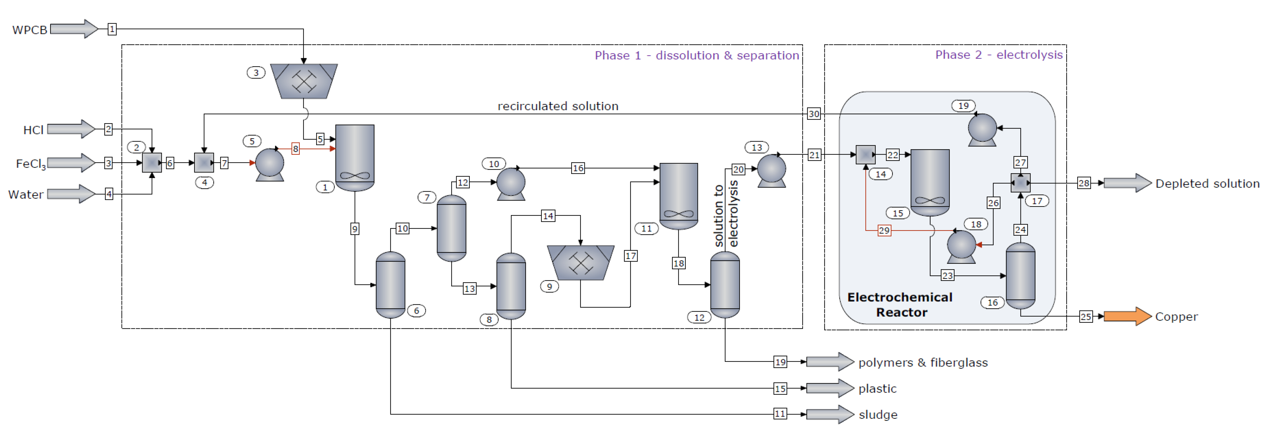
3.3. The Scaled-Up Dismantling Process
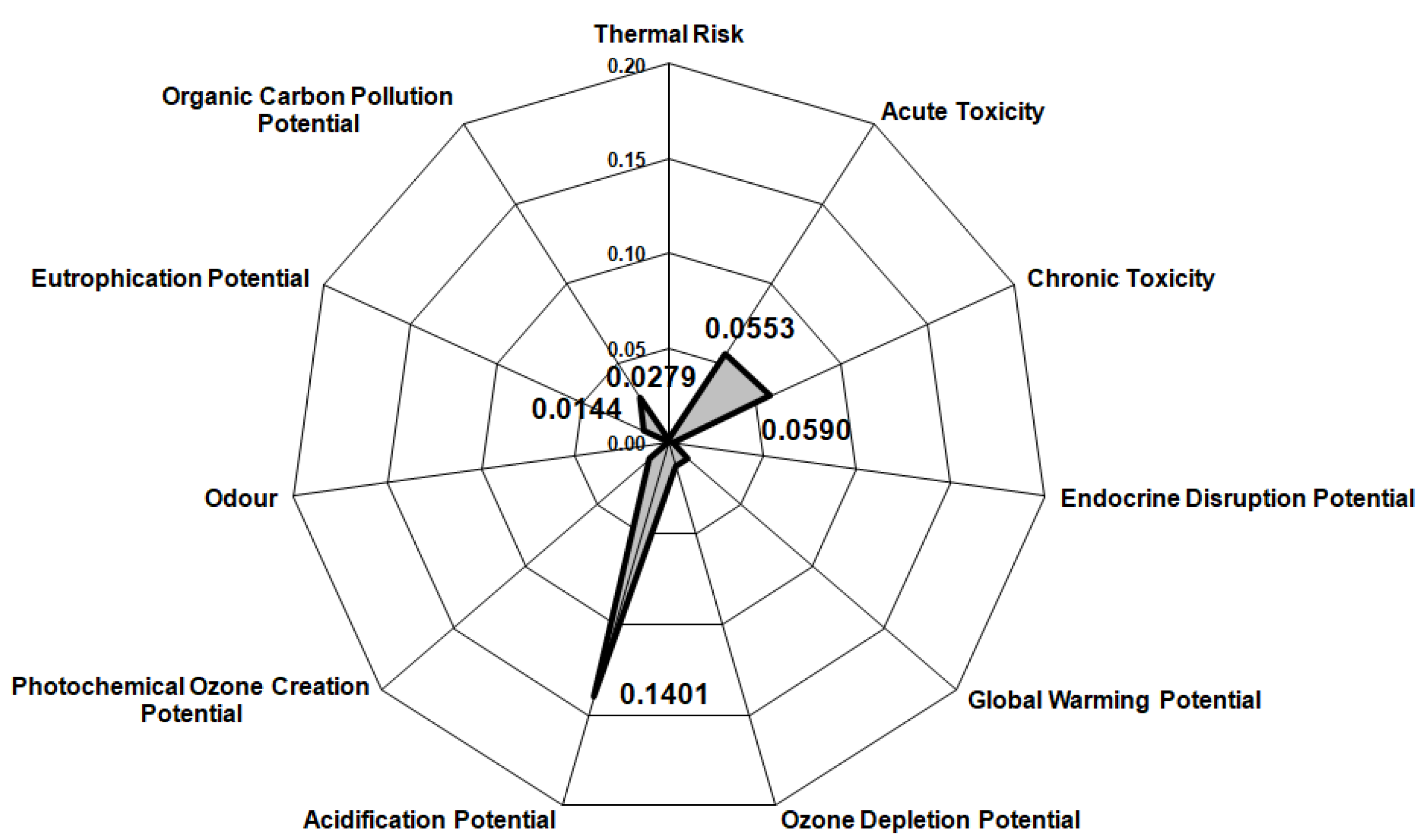
3.4. Environmental Assessment of the Scaled-Up Dismantling Process
4. Conclusions
Author Contributions
Funding
Institutional Review Board Statement
Informed Consent Statement
Data Availability Statement
Acknowledgments
Conflicts of Interest
References
- Tan, Q.; Liu, L.; Yu, M.; Li, J. An innovative method of recycling metals in printed circuit board (pcb) using solutions from pcb production. J. Hazard. Mater. 2020, 390, 121892. [Google Scholar] [CrossRef] [PubMed]
- Hao, J.; Wang, Y.; Wu, Y.; Guo, F. Metal recovery from waste printed circuit boards: A review for current status and perspectives. Resour. Conserv. Recycl. 2020, 157, 104787. [Google Scholar] [CrossRef]
- Bressanelli, G.; Saccani, N.; Pigosso, D.C.A.; Perona, M. Circular economy in the weee industry: A systematic literature review and a research agenda. Sustain. Prod. Consum. 2020, 23, 174–188. [Google Scholar] [CrossRef]
- Ning, C.; Hadi, P.; Aghdam, E.; Zhu, S.; Hui, D.C.-W.; Lin, C.S.K.; McKay, G. Environmental emission analysis of a waste printed circuit board-derived adsorbent production process. Chem. Eng. J. 2017, 326, 594–602. [Google Scholar] [CrossRef]
- Rieger, T.; Oey, J.C.; Palchyk, V.; Hofmann, A.; Franke, M.; Hornung, A. Chemical recycling of weee plastics—Production of high purity monocyclic aromatic chemicals. Processes 2021, 9, 530. [Google Scholar] [CrossRef]
- Shin, S.-R.; Mai, V.D.; Lee, D.-S. Chemical recycling of used printed circuit board scraps: Recovery and utilization of organic products. Processes 2019, 7, 22. [Google Scholar] [CrossRef] [Green Version]
- Siddiqi, M.M.; Naseer, M.N.; Abdul Wahab, Y.; Hamizi, N.A.; Badruddin, I.A.; Hasan, M.A.; Zaman Chowdhury, Z.; Akbarzadeh, O.; Johan, M.R.; Kamangar, S. Exploring e-waste resources recovery in household solid waste recycling. Processes 2020, 8, 1047. [Google Scholar] [CrossRef]
- Arya, S.; Patel, A.; Kumar, S.; Pau-Loke, S. Urban mining of obsolete computers by manual dismantling and waste printed circuit boards by chemical leaching and toxicity assessment of its waste residues. Environ. Pollut. 2021, 283, 117033. [Google Scholar] [CrossRef] [PubMed]
- Cucchiella, F.; D’Adamo, I.; Rosa, P.; Terzi, S. Automotive printed circuit boards recycling: An economic analysis. J. Clean. Prod. 2016, 121, 130–141. [Google Scholar] [CrossRef]
- Wang, R.; Zhu, Z.; Tan, S.; Guo, J.; Xu, Z. Mechanochemical degradation of brominated flame retardants in waste printed circuit boards by ball milling. J. Hazard. Mater. 2020, 385, 121509. [Google Scholar] [CrossRef]
- Flandinet, L.; Tedjar, F.; Ghetta, V.; Fouletier, J. Metals recovering from waste printed circuit boards (wpcbs) using molten salts. J. Hazard. Mater. 2012, 213-214, 485–490. [Google Scholar] [CrossRef] [PubMed]
- Cucchiella, F.; D’Adamo, I.; Lenny Koh, S.C.; Rosa, P. A profitability assessment of european recycling processes treating printed circuit boards from waste electrical and electronic equipments. Renew. Sustain. Energy Rev. 2016, 64, 749–760. [Google Scholar] [CrossRef] [Green Version]
- Sarvar, M.; Salarirad, M.M.; Shabani, M.A. Characterization and mechanical separation of metals from computer printed circuit boards (pcbs) based on mineral processing methods. Waste Manag. 2015, 45, 246–257. [Google Scholar] [CrossRef] [PubMed]
- Bizzo, W.A.; Figueiredo, R.A.; de Andrade, V.F. Characterization of printed circuit boards for metal and energy recovery after milling and mechanical separation. Materials 2014, 7, 4555–4566. [Google Scholar] [CrossRef] [PubMed]
- Wang, H.; Zhang, S.; Li, B.; Pan, D.A.; Wu, Y.; Zuo, T. Recovery of waste printed circuit boards through pyrometallurgical processing: A review. Resour. Conserv. Recycl. 2017, 126, 209–218. [Google Scholar] [CrossRef]
- Wang, J.; Guo, J.; Xu, Z. An environmentally friendly technology of disassembling electronic components from waste printed circuit boards. Waste Manag. 2016, 53, 218–224. [Google Scholar] [CrossRef] [PubMed]
- Zhao, C.; Zhang, X.; Shi, L. Catalytic pyrolysis characteristics of scrap printed circuit boards by tg-ftir. Waste Manag. 2017, 61, 354–361. [Google Scholar] [CrossRef] [PubMed]
- Birloaga, I.; Coman, V.; Kopacek, B.; Veglio, F. An advanced study on the hydrometallurgical processing of waste computer printed circuit boards to extract their valuable content of metals. Waste Manag. 2014, 34, 2581–2586. [Google Scholar] [CrossRef]
- Szalatkiewicz, J. Metals recovery from artificial ore in case of printed circuit boards, using plasmatron plasma reactor. Materials 2016, 9, 683. [Google Scholar] [CrossRef] [Green Version]
- Bacher, J.; Kaartinen, T. Liberation of printed circuit assembly (pca) and dust generation in relation to mobile phone design in a size reduction process. Waste Manag. 2017, 60, 609–617. [Google Scholar] [CrossRef] [PubMed]
- Lee, J.; Kim, Y.; Lee, J.C. Disassembly and physical separation of electric/electronic components layered in printed circuit boards (pcb). J. Hazard. Mater. 2012, 241, 387–394. [Google Scholar] [CrossRef] [PubMed]
- Khayyam Nekouei, R.; Maroufi, S.; Assefi, M.; Pahlevani, F.; Sahajwalla, V. Thermal isolation of a clean alloy from waste slag and polymeric residue of electronic waste. Processes 2020, 8, 53. [Google Scholar] [CrossRef] [Green Version]
- Zhang, Y.; Ji, G.; Ma, D.; Chen, C.; Wang, Y.; Wang, W.; Li, A. Exergy and energy analysis of pyrolysis of plastic wastes in rotary kiln with heat carrier. Process Saf. Environ. Prot. 2020, 142, 203–211. [Google Scholar] [CrossRef]
- Zhang, Y.; Ji, G.; Chen, C.; Wang, Y.; Wang, W.; Li, A. Liquid oils produced from pyrolysis of plastic wastes with heat carrier in rotary kiln. Fuel Process. Technol. 2020, 206, 106455. [Google Scholar] [CrossRef]
- Kumar, A.; Holuszko, M.; Espinosa, D.C.R. E-waste: An overview on generation, collection, legislation and recycling practices. Resour. Conserv. Recycl. 2017, 122, 32–42. [Google Scholar] [CrossRef]
- Silvas, F.P.; Correa, M.M.; Caldas, M.P.; de Moraes, V.T.; Espinosa, D.C.; Tenorio, J.A. Printed circuit board recycling: Physical processing and copper extraction by selective leaching. Waste Manag. 2015, 46, 503–510. [Google Scholar] [CrossRef] [PubMed]
- Ippolito, N.M.; Medici, F.; Pietrelli, L.; Piga, L. Effect of acid leaching pre-treatment on gold extraction from printed circuit boards of spent mobile phones. Materials 2021, 14, 362. [Google Scholar] [CrossRef] [PubMed]
- Cucchiella, F.; D’Adamo, I.; Lenny Koh, S.C.; Rosa, P. Recycling of weees: An economic assessment of present and future e-waste streams. Renew. Sustain. Energy Rev. 2015, 51, 263–272. [Google Scholar] [CrossRef] [Green Version]
- Torretta, V.; Ragazzi, M.; Istrate, I.A.; Rada, E.C. Management of waste electrical and electronic equipment in two eu countries: A comparison. Waste Manag. 2013, 33, 117–122. [Google Scholar] [CrossRef]
- Fogarasi, S.; Imre-Lucaci, F.; Ilea, P.; Imre-Lucaci, A. The environmental assessment of two new copper recovery processes from waste printed circuit boards. J. Clean. Prod. 2013, 54, 264–269. [Google Scholar] [CrossRef]
- Fogarasi, S.; Imre-Lucaci, F.; Imre-Lucaci, Á.; Ilea, P. Copper recovery and gold enrichment from waste printed circuit boards by mediated electrochemical oxidation. J. Hazard. Mater. 2014, 273C, 215–221. [Google Scholar] [CrossRef]
- Fogarasi, S.; Imre-Lucaci, F.; Egedy, A.; Imre-Lucaci, A.; Ilea, P. Eco-friendly copper recovery process from waste printed circuit boards using fe(3+)/fe(2+) redox system. Waste Manag. 2015, 40, 136–143. [Google Scholar] [CrossRef]
- Fogarasi, S.; Imre-Lucaci, F.; Fogarasi, M.; Imre-Lucaci, A. Technical and environmental assessment of selective recovery of tin and lead from waste solder alloy using direct anodic oxidation. J. Clean. Prod. 2019, 213, 872–883. [Google Scholar] [CrossRef]
- Cocchiara, C.; Dorneanu, S.-A.; Inguanta, R.; Sunseri, C.; Ilea, P. Dismantling and electrochemical copper recovery from waste printed circuit boards in h2so4–cuso4–nacl solutions. J. Clean. Prod. 2019, 230, 170–179. [Google Scholar] [CrossRef]
- Imre-Lucaci, A.; Fogarasi, M.; Imre-Lucaci, F.; Fogarasi, S. Chemical-electrochemical process concept for lead recovery from waste cathode ray tube glass. Materials 2021, 14, 1546. [Google Scholar] [CrossRef]
- Fogarasi, S.; Imre-Lucaci, F.; Varga, T.; Ilea, P. Eco-friendly leaching of base metals from waste printed circuit boards: Experimental study and mathematical modeling. Studia UBB Chem. 2012, LVII, 91–100. [Google Scholar]
- Hodisan, T.; Cimpoiu, C.; Haiduc, I.; Hodisan, S. Teorie si Aplicatii in Chimia Analitica; Risoprint: Cluj-Napoca, Romania, 2004. [Google Scholar]
- Imre-Lucaci, F. Electrochemical Methods for the Recovery of Copper from Waste Water and Solid Waste; Babes-Bolyai University: Cluj-Napoca, Romania, 2011. [Google Scholar]
- Chen, J.-Z.; Cao, H.-Z.; Li, B.; Yuan, H.-J.; Zheng, G.-Q.; Yang, T.-z. Thermodynamic analysis of separating lead and antimony in chloride system. Trans. Nonferrous Met. Soc. China 2009, 19, 730–734. [Google Scholar] [CrossRef]
- Beverskog, B. Pourbaix Diagrams for the System Copper-Chlorine at 5–100 °C; SKI Rapport 98:19; Available online: https://inis.iaea.org/search/search.aspx?orig_q=reportnumber:%22SKI-R--98-19%22 (accessed on 9 September 2021).
- Welham, N.J.; Kelsall, G.H.; Diaz, M.A. Thermodynamics of ag-cl-h2o, ag-br-h2o and ag-i-h2o systems at 298 k. J. Electroanal. Chem. 1993, 361, 39–47. [Google Scholar] [CrossRef]
- Senanayake, G. Gold leaching in non-cyanide lixiviant systems: Critical issues on fundamentals and applications. Miner. Eng. 2004, 17, 785–801. [Google Scholar] [CrossRef]
- Luyima, A.; Cui, W.; Heckman, C.; Moats, M.S. Examination of copper electrowinning smoothing agents. Part iv: Nucleation and growth of copper on stainless steel. Miner. Metall. Process. 2016, 33, 39–46. [Google Scholar] [CrossRef]
- Imre-Lucaci, Á.; Nagy, M.; Imre-Lucaci, F.; Fogarasi, S. Technical and environmental assessment of gold recovery from secondary streams obtained in the processing of waste printed circuit boards. Chem. Eng. J. 2017, 309, 655–662. [Google Scholar] [CrossRef]


| Motherboard 1 | Motherboard 2 | Motherboard 3 | Motherboard 4 |
|---|---|---|---|
| Type: ATI Radeon Xpress 200 (2004–>) Processor (Socket 478): Pentium 4 | Type: MSI P54C TR4 (1996–>) Processor (Socket 7): Pentium; AMD K5; Cyrix 6 × 86 | Type: Gigabyte GA-BX2000 (1999–>) Processor (Slot 1): Pentium II; Pentium III | Type: Intel Acorp 6VIA/ZX85 (2000–>) Processor (Socket 370): Pentium III |
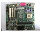 |  | 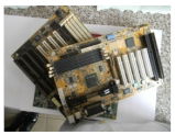 | 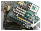 |
| Sample | Mass, g | Cu | Au | Ag | Sn | Pb | Ni | Zn | Fe |
|---|---|---|---|---|---|---|---|---|---|
| Motherboard 1 | 459.14 | 18.29 | 0.011 | 0.018 | 3.92 | 2.31 | 1.11 | 1.71 | 2.81 |
| Motherboard 2 | 488.45 | 19.6 | 0.009 | 0.015 | 4.1 | 2.16 | 1.27 | 1.92 | 3.01 |
| Motherboard 3 | 444.06 | 22.1 | 0.013 | 0.02 | 3.51 | 2.59 | 1.06 | 1.53 | 2.57 |
| Motherboard 4 | 482.68 | 23.1 | 0.01 | 0.016 | 3.76 | 2.64 | 1.19 | 1.67 | 2.93 |
| Potential Active Reaction | E° [V/HNE] | E’ [V/HNE] | Thermodynamic Equilibrium Constants |
|---|---|---|---|
| 1.52 | 1.02 | 25.42 | |
| 1.83 | 1.25 | 9.83 | |
| 0.79 | 0.48 | 5.25 | |
| 0.34 | 0.294 | 1.56 | |
| 0.52 | 0.21 | 5.14 | |
| −0.126 | −0.17 | 1.6 | |
| 0.762 | 0.747 | 1.05 | |
| −0.137 | −0.19 | 1.79 | |
| −0.0085 | −0.025 | 1.11 | |
| −0.26 | −0.28 | 0.7 | |
| −0.036 | −0.031 | −0.09 | |
| −0.44 | −0.402 | −1.276 | |
| −0.76 | −0.77 | 0.2 |
| Potential Active Reaction | E0 [V/HNE] | E’ [V/HNE] |
|---|---|---|
| 0.77 | 0.7 | |
| 0.16 | 0.37 | |
| 1.65 | 1.664 | |
| 0.154 | 0.14 |
| Redox Reaction | Redox Equilibrium Constant |
|---|---|
| Plastics | Boards | Chips and Small EC | Sludge | Solution |
|---|---|---|---|---|
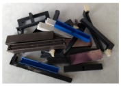 | 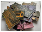 | 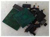 | 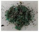 | 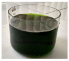 |
| Sample | Type of Fractions | Total Mass of Fractions | Metallic Composition, % | |||||||
|---|---|---|---|---|---|---|---|---|---|---|
| Cu | Au | Ag | Sn | Pb | Ni | Zn | Fe | |||
| Motherboard 1 | Plastics | 147.6 | - | - | - | - | - | - | - | - |
| Boards | 174.46 | 17.2 | - | - | - | - | - | - | - | |
| Chips and small EC | 29.21 | 8.3 | 0.05 | 0.1 | 0.75 | 0.15 | 0.75 | 0.15 | 1.64 | |
| Sludge | 9.73 | 3.65 | 0.37 | 0.05 | 28.72 | 36.7 | 1.09 | 0.02 | 0.4 | |
| Dissolved metals | 98.14 | 52.16 | 0 | 0.05 | 15.27 | 7.12 | 4.86 | 7.95 | 12.62 | |
| Motherboard 2 | Plastics | 166 | - | - | - | - | - | - | - | - |
| Boards | 172.2 | 23 | - | - | - | - | - | - | - | |
| Chips and small EC | 35.05 | 8.4 | 0.06 | 0.1 | 0.55 | 0.15 | 0.83 | 0.13 | 1.29 | |
| Sludge | 5.2 | 3.1 | 0.44 | 0.06 | 29.53 | 39.1 | 1.05 | 0.022 | 0.51 | |
| Dissolved metals | 110 | 48.20 | 0 | 0.03 | 16.63 | 7.70 | 5.33 | 8.48 | 12.93 | |
| Motherboard 3 | Plastics | 147.9 | - | - | - | - | - | - | - | - |
| Boards | 170.2 | 23.5 | - | - | - | - | - | - | - | |
| Chips and small EC | 20.8 | 8.7 | 0.03 | 0.1 | 0.68 | 0.13 | 0.91 | 0.18 | 1.51 | |
| Sludge | 8.1 | 3.65 | 0.64 | 0.05 | 26.83 | 34.8 | 1.02 | 0.025 | 0.47 | |
| Dissolved metals | 97.06 | 57.73 | 0 | 0.07 | 13.67 | 8.92 | 4.57 | 6.96 | 11.40 | |
| Motherboard 4 | Plastics | 145.8 | - | - | - | - | - | - | - | - |
| Boards | 141.55 | 20.2 | - | - | - | - | - | - | - | |
| Chips and small EC | 57.25 | 8.1 | 0.05 | 0.1 | 0.61 | 0.16 | 0.81 | 0.15 | 1.37 | |
| Sludge | 2.65 | 3.65 | 0.74 | 0.05 | 27.52 | 38.1 | 1.12 | 0.02 | 0.44 | |
| Dissolved metals | 135.43 | 57.72 | 0 | 0.01 | 12.60 | 8.60 | 3.88 | 5.89 | 9.85 | |
| Cu | Au | Ag | Sn | Pb | Ni | Zn | Fe |
|---|---|---|---|---|---|---|---|
| 20.77 | 0.011 | 0.017 | 3.83 | 2.42 | 1.16 | 1.71 | 2.84 |
| Unit | Parameters |
|---|---|
| Leaching reactor | Temperature: 25 °C |
| Residence time 24 h | |
| 0.3 M FeCl3 in 0.5 M HCl | |
| Electrochemical reactor | re = 90.12% |
| rc = 72.69% | |
| Wc = 1.59 kWh/kg | |
| Processed WPCBs | 100 kg/h |
| Pump efficiency | 90% |
| Heat exchanger ΔTmin. | 10 °C |
| Heat exchanger pressure drop | 1–3% |
| Input | Output | ||
| Component | kg/h | Component | kg/h |
| WPCBs | 100 | Copper deposit | 18.7 |
| Leaching solution | 623.4 | Sludge | 3.7 |
| Plastic | 32.4 | ||
| Epoxy resin | 14.5 | ||
| Fiber glass | 15.1 | ||
| Depleted solution | 634 | ||
| TOTAL | 723.4 | TOTAL | 723.4 |
| Process Equipment | Energy, (MJ/h) | ||
|---|---|---|---|
| Type | ID | Added | Extracted |
| Crusher | 3, 9 | 0.212 | - |
| Reactor | 1 | 2.08 | 211.545 |
| Reactor | 11 | 1.07 | 45.407 |
| Separators | 6, 8, 12 | 25.617 | - |
| Electrochemical Reactor | 15 | 144.17 | - |
| Pumps | 5, 10, 13, 18, 19 | 1.398 | - |
| TOTAL: | 174.5470 | 256.952 | |
Publisher’s Note: MDPI stays neutral with regard to jurisdictional claims in published maps and institutional affiliations. |
© 2021 by the authors. Licensee MDPI, Basel, Switzerland. This article is an open access article distributed under the terms and conditions of the Creative Commons Attribution (CC BY) license (https://creativecommons.org/licenses/by/4.0/).
Share and Cite
Fogarasi, S.; Imre-Lucaci, Á.; Imre-Lucaci, F. Dismantling of Waste Printed Circuit Boards with the Simultaneous Recovery of Copper: Experimental Study and Process Modeling. Materials 2021, 14, 5186. https://doi.org/10.3390/ma14185186
Fogarasi S, Imre-Lucaci Á, Imre-Lucaci F. Dismantling of Waste Printed Circuit Boards with the Simultaneous Recovery of Copper: Experimental Study and Process Modeling. Materials. 2021; 14(18):5186. https://doi.org/10.3390/ma14185186
Chicago/Turabian StyleFogarasi, Szabolcs, Árpád Imre-Lucaci, and Florica Imre-Lucaci. 2021. "Dismantling of Waste Printed Circuit Boards with the Simultaneous Recovery of Copper: Experimental Study and Process Modeling" Materials 14, no. 18: 5186. https://doi.org/10.3390/ma14185186
APA StyleFogarasi, S., Imre-Lucaci, Á., & Imre-Lucaci, F. (2021). Dismantling of Waste Printed Circuit Boards with the Simultaneous Recovery of Copper: Experimental Study and Process Modeling. Materials, 14(18), 5186. https://doi.org/10.3390/ma14185186