Abstract
This paper presented a new approach to decision making support of defects assessment in metal matrix composites (MMC). It is a continuation of the authors’ papers in terms of a uniform method of casting defects assessment. The idea of this paper was to design an open-access application (follow-up system called Open Atlas of Casting Defects (OACD)) in the area of industry and science. This a new solution makes it possible to quickly identify defect types considering the new classification of casting defects. This classification complements a classical approach by adding a casting defect group called structure defects, which is especially important for metal matrix composites. In the paper, an application structure, and the possibility of its use in casting defects assessment were introduced.
1. Introduction
Metal composites are increasingly replacing traditional materials used in construction, aviation, and in the construction of machinery and equipment and in many other fields. This is due to the ability to obtain virtually any set of desirable functional properties of the material, such as a high damping factor, high resistance to abrasion, high Young’s modulus, low specific weight, and low coefficient of thermal expansion. According to Konopka at el., the definition of composite material presented in publications [1,2,3] is as follows: “Composite material is created by tightly binding at least two chemically and physically different materials together in such a way that, while maintaining a good and permanent connection of the components, a clear boundary is maintained between them and that the distribution of reinforcing components throughout the entire matrix volume is as uniform as possible”. This definition describes an ideal composite material with a perfect structure. Real composite materials generally have imperfect structures—composite materials contain various defects [1,2,4,5,6,7,8,9,10,11,12], especially when considering cast composites. Castings feature a specific structure that is related to the course of the manufacturing process [13,14,15,16,17,18,19,20,21,22,23,24]. The classification of these irregularities makes it possible to:
- -
- Precisely identify them;
- -
- Determine why they form;
- -
- Determine which manufacturing stage causes their formation;
- -
- Promptly take countermeasures.
There is no such classification in the case of metal composite castings. Essam M. [25] confirms this, presenting the surface defects of composites with aluminum matrix and Al2O3 reinforcement, and especially the assessment of the distribution homogeneity of the reinforcing phase [25] and macroscopic studies. No scheme or key describing irregularities in the structure of these materials was used. The authors of this paper meticulously, but without confirmation with any standard, intuitively identified and interpreted all defects, which caused some problems in the reception of the publication. In contrast, Mamalis et al. also documented defects that occurred during the processing of composite materials (e.g., the fiber-reinforced materials, metal matrix composites, ceramic matrix composites and bonded materials) [26]. Although the work is a valuable supplement to knowledge related to the alleged mechanism of reliability of composites during their useful life, there are no clear terms enabling the efficient assessment of the work of the material by a diagnostician or an operator. On the other hand, the classification of defects in castings of traditional materials (cast iron, cast steel, non-ferrous metal alloys) is insufficient and must be supplemented with specific defects of those materials. This problem, which was noticed during the description of the structure and quality of metal composite castings, was the reason for undertaking works on the development of such classification and, as a result, for this work to be created. This paper presented a new approach to decision making support of defects assessment in metal matrix composites (MMC). It is a continuation of the authors’ papers in terms of a uniform method of casting defects assessment. The idea of this paper was to design an open-access application (follow-up system called Open Atlas of Casting Defects, OACD) in the area of industry and science. Simulation codes currently used in the foundry industry are primarily used to predict casting quality, quality tied mainly to the location of defects such as shrinkage (voids of shrinkage origin). Prediction of zones exposed to other casting defects (i.e. erosion of mould, the presence of non-metallic inclusions, zones exposed to "hot tears", to penetration of the mould by the liquid alloy) takes place on the basis of models –empirical formulas (called soft) or indirectly on the user’s knowledge and analysis of the results of simulation, for example, speed field of metal stream in the mould cavity or the time-temperature image of cast and mould interaction. Other modules used in foundry simulation codes taking into account the diffusion of alloying elements (Fick’s equation) or thermomechanical processes enabling modeling of stress in a casting-mould system using constitutive equations. These activities are the basis for decisions concerning the selection of the optimal casting technology with the expectation of obtaining the final, acceptable version of the concept, taking into account the criterion of the best relationship of quality/price of the casting. This made it possible to eliminate, commonly used over the years, classical method of trial and error in the design process of casting technology, completed only through intuition of engineers, specimen castings and experimental tests. The technologists with simulation system and with the results of calculations using this tool, take decision on the basis of their assessment and based on the above, then suggest the next version after the change of technology/casting design or approve designed technology.
The scope of the paper includes the classification of defects, taking into account foundry iron alloys, i.e., alloy of iron with carbon up to 1.5% C in the cast state—cast steel and an alloy of iron with carbon from 2.11–4.3% C in the cast state—cast iron, and non-ferrous metal alloys, mainly aluminum with silicon—silumines and metal composites’ liquid matrix technologies (direct methods—in situ: production of composites by mechanical mixing and indirect methods—ex-situ: production of composites by mechanical mixing and production of composites by saturating the porous structure with liquid matrix metal).
2. Classification of Metal Matrix Composites
2.1. Division of Composite Materials
Composite materials can be divided depending on the production method, intended use, technological properties, and depending on the matrix as well. Metal matrix composites are currently produced with a variety of methods, which include but are not limited to [2,3,27,28,29,30,31,32,33,34,35,36,37,38,39,40,41,42,43,44,45,46,47]:
- -
- Liquid matrix technologies (only these will be the subject of this paper because it concerns defects of castings);
- -
- Deformation technologies, i.e., those that use plastic processing methods;
- -
- Sinter technologies.
In the liquid matrix technology, there are two fundamentally varying methods of composite production, such is direct methods, and indirect methods [2,3,8,28,30,32,37,38,44,45,46,47].
2.2. Direct Methods in Which the So-Called “In Situ” Composites Are Made
In situ composites belong to the group of composite materials in which the reinforcing phase is formed in the matrix material in the composite production process. In this process, it is possible to obtain reinforcement with various structures and properties. The reinforcing phase can be in the form of dispersion particles or fibrous phases; it can be ductile or brittle.
There are many methods for obtaining this type of composite [2,3,32]. Reinforcement may occur in processes involving the liquid phase (Figure 1) or the solid phase. The production of reinforcement from the liquid phase can occur in the process of crystallization, for example, in directional crystallization of eutectic systems, by strong gas supercooling of supersaturated solutions or a rapid reaction between components in the liquid phase. Processes using internal oxidation, substitution reactions or reactive component grinding are methods of producing in situ composites with the participation of the solid phase [2,32].
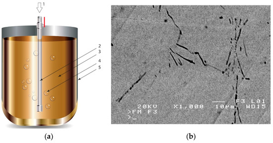
Figure 1.
Production of a composite in a liquid—gas system: (a) scheme: 1—gas, 2—gas lance, 3—liquid metal, 4—gas bubbles, 5—crucible; (b) SEM image of the in-situ Al3Mg with N2 composite.
2.3. Indirect Methods, Called Ex-Situ Methods
In the case of these composites, castings are obtained in two ways. The first method involves mixing the liquid matrix, which is a technical alloy (Figure 2) with fixed reinforcement (suspension composites) [2,3,41,45]. The composite suspension is most often obtained by introducing ceramic particles to the liquid alloy matrix: during the mechanical mixing, by dissolving the composite concentrate, blowing ceramic particles using gas or ultrasonic or electromechanical mixing.
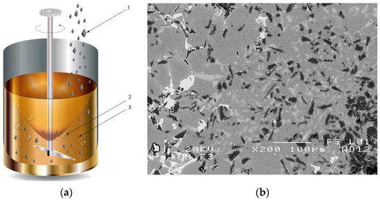
Figure 2.
Production of composites by mechanical mixing: (a) scheme: 1—particles-reinforcing phase, 2—gas bubbles, 3—liquid metal; (b) SEM image of the ex-situ composite microstructure (suspension composite: matrix—Al alloy, reinforcement—SiC particles).
Light alloys such as aluminum, magnesium, lithium, titanium as well as copper, iron and their alloys are most commonly used for the matrix. The reinforcing phase is constituted by graphite, glass, aluminum, silicon, zirconium, titanium, cerium oxides, as well as silicon and titanium carbides or boron nitride. The reinforcement is in the form of particles with granularity ranging from a few to several hundred micrometers or fibers with a diameter of 0.2–4 mm and length of 0.5–2.0 mm. Its concentration in the matrix reaches 30%.
The second method involves saturating the porous structure of the composite reinforcing phase with a liquid technical alloy (composites with saturated reinforcement), most often under pressure [1,2,3,8,38], Figure 3. Various metals and their alloys can be used as the matrix. Due to manufacturing difficulties, casting temperature and activity in relation to the environment may be a barrier to their use. For these reasons, aluminum and magnesium alloys, some copper alloys and, to a lesser extent, low fusible alloys, are mainly used. The reinforcement of saturated composites can be constituted by metal materials, e.g., carbon and alloy steels, and non-metallic materials, e.g., ceramics (aluminosilicates, carbon-graphite), boron, polymeric materials [2,3]. These materials may be in the form of structured long fibers, yarn, fabric, mat, unstructured short fibers, cotton wool, wool, cellular structures, sinters, etc.
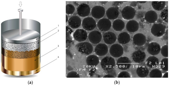
Figure 3.
Production of composites by saturating the porous structure with liquid matrix metal: (a) scheme of the mould together with a moulder—preform during saturation, 1—stamp-piston, 2—ceramic moulder partly saturated with metal, 3—metal, 4—metal sleeve; (b) SEM image of the composite boundary with saturated reinforcement (Al alloy with C fibers).
3. Classification of Defects in Castings of Various Metal Materials
The factor determining the procedure in the casting production process is the request (order) of the recipient which specifies their needs regarding the casting [1,48]. This factor affects further proceedings. The quality of castings is affected, among others, by factors related to the requirements specified in the order, as well as strictly technological factors such as casting process design, casting materials and metal melting, mould filling with metal, solidification, crystallization, cooling and removal of the casting from the mould.
Failure to meet the above requirements may result in the formation of defects in castings. All metal castings have defects of various types and origins. Any deviation in the characteristics, structure and mechanical or physicochemical properties of a material from the applicable requirements can be called a casting defect or defects [13,16,48,49,50,51,52,53,54,55,56,57,58,59,60,61,62]. Defects can be identified based on their features, which in turn leads to the creation of the casting defect classification. This classification is useful for:
- -
- Transfer of information in research work, during the educational process, or in the manufacturing process;
- -
- Elimination of defective castings from further stages of the manufacturing process;
- -
- Intervention activities aimed at removing the causes of defect formation from the manufacturing process.
Regarding the second case, a classification criterion of defective castings is a division of castings into three casting groups [13,16,61,62,63,64,65,66,67]:
- -
- Satisfactory castings with acceptable defects;
- -
- Castings with repairable defects;
- -
- Castings with disqualifying defects.
For castings made from traditional materials, there are standards, atlases, or catalogues of defects [13,16,27,57,61,62,63,64], which:
- -
- Enable unequivocal identification of defects;
- -
- Provide methods to detect them;
- -
- Provide causes of their formation;
- -
- Suggest technological means to prevent their formation.
They also include numerous publications that identify, describe or detect defects in castings. Zhao et al. presented a defect description system based on the Radiographic Images and Sparse Representation-based Classification (SRC) [65]. However, only four popular types of casting defects, including cracks, blow holes, shrinkage porosities and shrinkage cavities, were considered in this system. Elbel et al. [67] described the quality of spheroidal graphite iron and especially the formation of voids and holes as a result of reactions occurring during casting operations. The impact of process parameters on the formation of defects was also assessed in this work. Unfortunately, no identical terms were found in this work for the voids interchangeably referred to in the text, it was impossible to relate these defects to any classification, which greatly hinders the understanding process. In Europe, there are classification systems for casting defects in France, England, Germany, and Poland. Classification schemes of defects in these castings are presented in Figure 4.
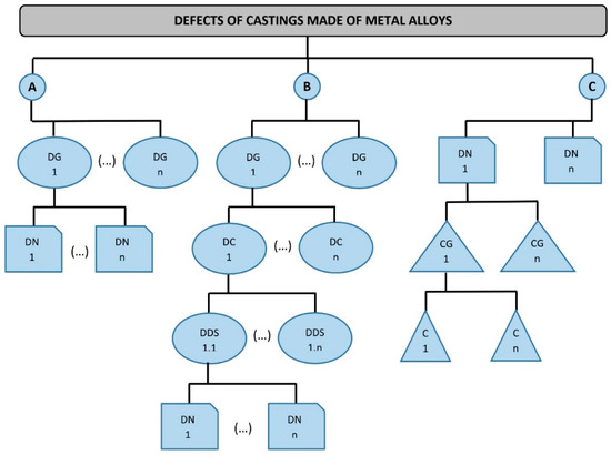
Figure 4.
Classification schemes of defects in castings from traditional materials (own elaboration on the basis of references [27,57,60,61,63,64,66]): A—according to Polish standards, B—according to French standards, C—according to the English and German systems, DG—defect group, DN—defect name, DC—defect characteristics, DDS—more detailed defect specification, CG—cause group, C—cause.
In Poland, there is a division [64] in which two levels are distinguished (flow A). At the upper level, 4 defect groups are identified. At the lower level, each group is assigned defects with specific features. These defects were given names that help unambiguously identify them.
In the French foundry industry, a multi-level structure is used [58,60,61,63] whose first level contains seven groups named, respectively:
- -
- Outer metal gain;
- -
- Inner and outer cavities;
- -
- Breaks in casting continuity;
- -
- Surface defects;
- -
- Incompleteness of the product;
- -
- The inaccuracy of dimensions or shape;
- -
- Structural inclusions or anomalies.
The lowest level also contains the names of individual defects, but between this level and the defect group definition, there are two intermediate levels containing additional features of a given group or subgroup (flow B). This way, each defect is assigned certain characteristics to make it easier to identify its causes and take preventive actions [58,60,63].
In the English and German literature, defects are classified in a different manner [56,57,63]. The classification of defects in accordance with BS 2737: 1956 [56,57,60,61,62,63] includes terminology of internal casting defects identified by ultrasonic flaw detection.
The principle of this division is presented in Figure 4 (flow C). The names of defects are presented directly here, and they are assigned to cause groups and the particular causes of their formation. It includes a defect atlas illustrated with 65 reproductions of radiographs or micrographs. This division would be very convenient for identification, but some causes were defined somewhat inaccurately. Since several defects may have a common cause, this division may not always be used objectively. A proposal for systematics of defects was also presented by Guy [60], and this paper was inauspiciously translated as “Atlas of Casting Defects” [61] and presented as a work resulting from French-German cooperation. It also adopts a division into seven classes marked with letters:
- Metallic growth;
- Cavities;
- Breaks in continuity;
- Surface defects;
- Incomplete casting;
- Incorrect dimensions or shapes;
- Inclusions or abnormal structure.
Each class is divided into groups, and those in turn into subgroups marked with letters, a given defect is determined by a letter and a number, which makes it possible to position it in the classification. However, the names of defects vary depending on geographical regions and depend on the people using the classification, which prevents international polemics and communication. It is identical in the French and German versions. This classification is a very valuable collection of information; however, the multitude of markings and the lack of unambiguous terms introduce some chaos and raise some controversy among cast manufacturers. It is a great tool for scientists, but it is too complicated and difficult to read for employees who are the basic staff of a foundry.
Kassie et al. characterized steel casting defects in their project. Unfortunately, they only provided a detailed description of two defects of castings from these materials, which in their opinion have the greatest impact on the quality of the product, i.e., gas defects and shrinkage defects [56].
Noteworthy is the paper of Garat et al., who, in the first part of their paper, classified defects into eight groups, i.e., incorrect shapes—core and pin offset, incorrect dimensions, defective surfaces, discontinuity (cracking), metal growths, cavities, inclusions, typical defects of rheocasting in the semi-solid state (formes incorrectes—déport des noyaux et des broches, dimensions incorrectes, surfaces défectueuses, solution de continuité (fissuration), excroissances métalliques, cavités, inclusions, défauts typiques du rhéomoulage à l’état semi-solide) [62]; however, this paper applies only to aluminum alloys. Interest in aluminum alloys in recent years is due to their prevalence [62,67,68,69,70,71,72,73,74], thanks to their low density combined with good mechanical and corrosive properties. In 2015, Fiorese, et al. created a new classification for defects in aluminum alloy castings [74]. This work proposes a multi-level classification of structural defects. The first level distinguishes defects based on their location (internal, external or geometric), the second level distinguishes defects based on their metallurgical origin.
Polish classification of defects in metal castings is one of the few classifications covered by governmental standards. As can be seen in Figure 4, this classification (flow A) is the simplest because of its two-stage arrangement. Its additional feature is a clear division of defects in castings made from different materials. The features specified as well as the wide availability and familiarity of this classification in Poland make it necessary to refer to this classification while attempting to create any other classification. Thus, further considerations will be based on the distribution of defects contained in it. For this reason, a more detailed description of this classification is needed. According to the Polish standard [64] as well as national studies, e.g., atlases [13,61], this classification contains four groups of defects, listed in Figure 5.
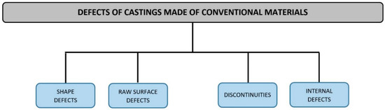
Figure 5.
Defects of castings from traditional materials (steel, cast iron, non-ferrous alloys).
The order of defect groups is consistent with the sequence of operations in the casting acceptance by the quality control department. Shape defects are observed first, followed by raw surface defects, and discontinuities. Internal defects are detected during non-destructive and destructive testing as well as during machining of castings. Each of the four groups is assigned certain defects, which are marked with “W”, and the type of material in which they occur is indicated in Table 1.

Table 1.
Classification of defects in castings from traditional materials (own study according to the Polish Standard [64]).
The Polish Standard (PN-85/H-83105) also provides indicative causes of defects. In other studies [13,53,54,55,57,59], which properly extend this standard, methods of detection of defects formed were also found.
4. Classification of Defects in Metal Composite Castings and a Proposal for the Division of Defects in Castings Made from Traditional Materials (Cast Steel, Cast Iron, Non-Ferrous Alloys) and Composite Materials
This paper proposes a classification of defects in the structure of metal composite castings, which is a group in the classification of casting defects. This group is called structural defects. Other groups of defects (defects in shape and defects in the raw surface) covered by the classification correspond to the groups appearing in the classification of defects in castings made from traditional materials (according to PN-85/H-83105—Figure 5). This group (structural defects) consists of four subgroups covering the defects in the structure of castings made from traditional materials, which, at the same time, correspond to the defects in the structure of composite castings (Figure 6).
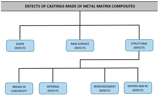
Figure 6.
Structure of classification of defects in metal composite castings.
The classification of defects in the structure of metal composite castings is presented in Table 2. The layout of the table is similar to that in the Polish Standard [64]. It presents the qualification of a defect into the appropriate subgroup of defects in the structure of metal composite castings, as is described; the scheme is supported by an example of the defect, the causes of defects in the structure of metal composite castings are presented based on the studies [1,2,3,28,32,33,47] and their detection methods in accordance with studies of the authors [1,39,40,41,42,43,44,75,76,77,78,79,80,81,82,83,84,85,86,87,88,89,90,91,92,93,94,95,96] is proposed. Table 3 presents a proposal for the division of defects in castings made from traditional materials (cast steel, cast iron, non-ferrous alloys) and composite materials compatible with standard PN-85/H-83105 [67]. The nomenclature for marking a specific defect (numbering), in the case of composite casting defects, has been supplemented by the author’s proposition according to the key: W-Group-Subgroup-Sequential No. For example, W-400-32-1 means the first defect (1) of the type “Inclusions” (400) classified into group 3 (structural defects), subgroup 2 (internal defects).
Table 2.
Classification of defects in the structure of metal composite castings (description of defects in metal composites proposed by the authors).
Table 3.
Proposed division of defects in castings made from traditional materials (cast steel, cast iron, non-ferrous alloys) and all composite materials.
5. Open Atlas of Casting Defects Project
Computer-aided production processes [84,85,97,98], including casting as well as an assessment of the quality of castings using computer software for their diagnostics is a constantly developing field of science [86,87,88,89,90]. From the point of view of casting production, wide, quick access to industry information, databases, standards, consulting and technological descriptions is very important. Decision support and diagnostics, in the case of foundries, allow for the use of software tools and computer hardware of various types [63,88,89,90]. An example of such an application can be the study of Kluska-Nawarecka, which focuses on the problems related to creating formal descriptions of knowledge about defects. It presents the methodology of creating models using neural networks and genetic algorithms in the field of defect diagnostics [63]. El-Tokhy et al. developed digital control of casting defects using radiographic X-ray images [76]. In this work, an artificial neural network is used as a classifier to match the objectives of the identified product features, and three different algorithms introduced automatically to detect casting defects on X-rays. Automation of the diagnostic process is not only conducive to improving the quality of the product, it also facilitates control and improves the manufacturing process, and increases efficiency and profitability by reducing labor costs [63,69,89,90,98]. Mery et al., on image processing to detect damage in aluminum and steel castings, described the main aspects of the automatic unit for X-ray control of products [69]. Perzyk [97] characterized the main possibilities and potential applications of data mining in the casting manufacturing industry. This work identifies the main types of data mining techniques, including statistics, artificial intelligence, databases, and visualization tools. Statistical methods and visualization methods are presented in more detail, showing their general capabilities and advantages as well as characteristic examples of applications in foundry production.
All the above-mentioned premises, as well as the development of the author’s classification of casting defects based on the standard [64], which also takes defects of castings from metal composites into account, prompted the authors of the article to develop the Open Atlas of Casting Defects (OACD). It is a continuation of the authors’ paper [1,54,55,98,99,100] and ultimately aims to provide an open access platform for casting manufacturers, their customers and researchers involved in the assessment of casting defects and the origin of their formation. The open access formula will allow users to modify and complement data, and constantly update knowledge of castings and their defects. The rest of the chapter presents the capabilities and functions of the Open Atlas of Casting Defects, whose working draft is designed in Excel and Visual Basic for Applications (VBA). Ultimately, it will be a web-based expert program based on the follow-up system using modern internet technologies, such as: HTML 5.0, PHP, Java, Ajax.
The main window of the program (Figure 7) allows you to choose the method of working with the Open Atlas of Casting Defects. In addition to typically administrative functions related to login, privileges and settings of the atlas, the user has the possibility to:
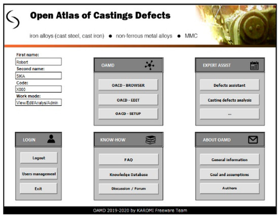
Figure 7.
The main window of the Open Atlas of Casting Defects.
- -
- View the atlas of defects containing casting defects and their detailed description (view mode, code C001);
- -
- View casting defects’ classifications (view mode, code C001);
- -
- Search for casting defects using many different criteria (view mode, code C001);
- -
- Edit the knowledge base—modify and complement information on casting defects (edit mode, code B001);
- -
- Obtain expert advice (analysis mode, code A001);
- -
- Use the forum to exchange experience and knowledge (analysis mode, code A001);
- -
- Open atlas of casting defects management (admin mode, code X001).
The user can access descriptions of individual defects in various ways, depending on their needs. On the one hand, the user can search for a given defect using the drop-down menus in the window presenting the classification of defects (Figure 8). It contains defects of castings made from traditional materials (cast steel, cast iron, non-ferrous alloys) and composite materials. By choosing individual options, in several steps through groups of defects and their subgroups, the user “arrives at” the defect that interests them and its description. On the other hand, it is possible to search for a given defect using the criteria available in the program (i.e., Defect Name, Marking, Occurrence, Defect Description, Alleged Cause, Detection Method). The user, knowing the name or cause of the defect, can search for the defect that interests them. As the research and experience of the authors based on conducted work in industry show, this top-down approach with the possibility of multi-criteria search is very desirable for quality controllers. Figure 9 shows how to search for a specific defect, taking its name into account.
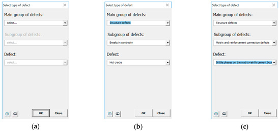
Figure 8.
Open Atlas of Casting Defects: (a–c) searching for a defect in the window containing the classification of defects in castings made from traditional materials and composite materials.
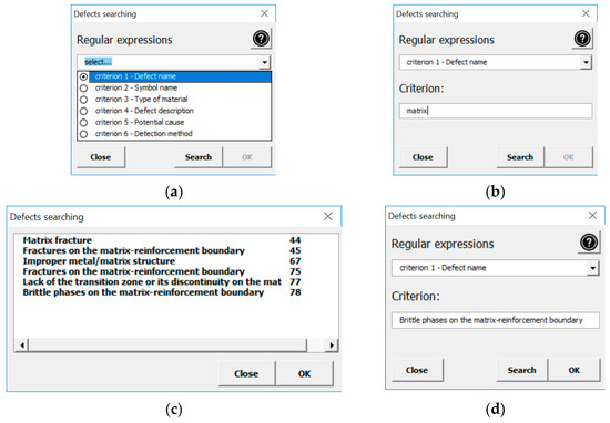
Figure 9.
Open Atlas of Casting Defects: (a–d) searching for a defect in the window containing the search criteria.
The most important element of the Open Atlas of Casting Defects is the knowledge base containing a detailed description of casting defects. A representative of this knowledge base in the form of a program window is shown in Figure 10 for the defect: “Brittle phases on the matrix-reinforcement boundary”. The user can obtain information about:
Figure 10.
The window containing a detailed description of the defect.
- -
- Qualification of the defect;
- -
- Name/names of the defect—this field contains valid/acceptable/common names of the given defect;
- -
- Defect code—the code assigned to the classification of a defect of castings made from traditional materials (cast steel, iron, non-ferrous alloys) and composite materials on which the Open Atlas of Casting Defects is based;
- -
- Occurrence in a given material group—is the defect present in castings made from traditional or composite materials;
- -
- Description of the defect that occurred;
- -
- Causes of the defect;
- -
- Defect detection method.
In addition to the verbal description of casting defects, each defect is also accompanied by its scheme (cf. Figure 10) and picture (Figure 11) (pictures of actual casting defects updated on a regular basis for various produced series shown on the casting fragments for defects visible on the surface and on properly cut and prepared samples for internal defects).
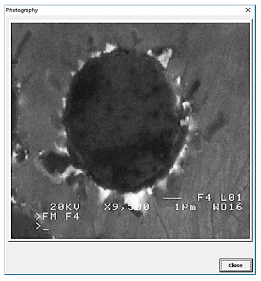
Figure 11.
The window containing a picture of the defect.
6. Conclusions
The results of analyses and theoretical findings, as well as experimental research presented in the paper, allow to draw the following conclusions:
1. The classification of structure defects appearing in castings of cast metal composites proposed in the paper allows to:
- -
- Complement the classification of defects in castings of traditional materials, with the group of defects characteristic for castings being a concern of this paper;
- -
- Unequivocally define defects characteristic for castings of studied composites;
- -
- Supplement the proposed classification with possible defects not taken into consideration thanks to its open character;
2. Determining the causes of defects covered by the classification as a result of analysis of the process of manufacturing castings made from tested composites is facilitation in undertaking actions aimed at eliminating these defects;
3. The presented classification of defects in metal composite castings complemented by the causes of their formation as well as methods of their detection and identification may constitute the starting point for the development of an expert program, which would support undertakings related to quality control.
Author Contributions
Conceptualization, R.S. and K.G.; Data curation, D.C.-K. and P.S.; Formal analysis, D.C.-K. and D.P.; Funding acquisition, P.P.; Investigation, M.R., P.P., D.P. and K.G.; Methodology, R.S., P.P., D.C.-K. and K.G.; Resources, P.P. and P.S.; Software, M.R.; Supervision, R.S., P.P. and K.G.; Validation, R.S.; Writing—original draft, M.R., D.C.-K. and K.G.; Writing—review and editing, P.P. and D.P. All authors have read and agreed to the published version of the manuscript.
Funding
The research presented in this article was carried out under the Grant of the Ministry of Science and Higher Education of Poland number 0613/SBAD/4630 performed at the Poznan University of Technology, Poland.
Conflicts of Interest
The authors declare no conflict of interest.
References
- Gawdzińska, K.; Chybowski, L.; Przetakiewicz, W. Proper matrix-reinforcement bonding in cast metal matrix composites as a factor of their good quality. Arch. Civ. Mech. Eng. 2015, 16, 553–563. [Google Scholar] [CrossRef]
- Konopka, Z. Metalowe Kompozyty Odlewane; Wydawnictwo Politechniki Częstochowskiej: Częstochowa, Poland, 2011. [Google Scholar]
- Sobczak, J. Metal Matrix Composites; Institute of Foundry and Institute of Motor Transport: Cracow/Warsaw, Poland, 2001. [Google Scholar]
- Hari Babu, N.; Tzamtzis, S.; Barekar, N.; Patel, J.B.; Fan, Z. Fabrication of Metal Matrix Composites under Intensive Shearing. Solid State Phenom. 2008, 141–143, 373–378. [Google Scholar]
- Qi, L.; Liu, J.; Guan, J.; Su, L.; Zhou, J. Damage prediction for magnesium matrix composites formed by liquid-solid extrusion process based on finite element simulation. Trans. Nonferrous Met. Soc. China 2010, 20, 1737–1742. [Google Scholar] [CrossRef]
- Zhao, C.; Zhou, Y.; Xing, X.; Liu, S.; Ren, X.; Yang, Q. Precipitation stability and micro-property of (Nb, Ti)C carbides in MMC coating. J. Alloys Compd. 2018, 763, 670–678. [Google Scholar] [CrossRef]
- Olszówka-Myalska, A.; Chrapoński, J. Study of interaction between liquid magnesium alloy and glassy carbon particles. Solid State Phenom. 2015, 227, 178–181. [Google Scholar] [CrossRef]
- Konopka, K.; Olszówka-Myalska, A. Composites ceramic-metal with int. Mater. Chem. Phys. 2003, 81, 329–332. [Google Scholar] [CrossRef]
- Kong, X.; Yang, L.; Zhang, H.; Chi, G.; Wang, Y. Optimization of surface roughness in laser-assisted machining of metal matrix composites using Taguchi method. Int. J. Adv. Manuf. Technol. 2017, 89, 529–542. [Google Scholar] [CrossRef]
- Bakkar, A.; Ahmed, M.M.Z.; Alsaleh, N.A.; Seleman, M.M.E.-S.; Ataya, S. Microstructure, wear, and corrosion characterization of high TiC content Inconel 625 matrix composites. J. Mater. Res. Technol. 2019, 8, 1102–1110. [Google Scholar] [CrossRef]
- Olszówka-Myalska, A.; Myalski, J. Applying stir casting method for Mg alloy-short carbon fiber composite processing. Compos. Theory Pract. 2019, 14, 81–85. [Google Scholar]
- Olszówka-Myalska, A. Spiekane kompozyty magnezowe typu in sit. Mechanik 2016, 5, 504–505. [Google Scholar] [CrossRef]
- Falęcki, Z. Analysis of Casting Defects; AGH: Crakow, Poland, 1997. [Google Scholar]
- Orłowicz, W.; Tupaj, M.; Mróz, M.; Guzik, E. Evaluation of ductile iron casting material quality using ultrasonic testing. J. Mater. Process. Technol. 2010, 210, 1493–1500. [Google Scholar] [CrossRef]
- Ghosh, A.; Mallik, A.K. Manufacturing Science; Ellis Horwood: New York, NY, USA, 1986. [Google Scholar]
- David, N. Casting Defects Handbook; American Foundry Society: Schaumburg, IL, USA, 2005. [Google Scholar]
- DeGarmo, E.P.; Black, J.T.; Kohser, R.A. Materials and Processes in Manufacturing, 8th ed.; John Wiley & Sons: Hoboken, NJ, USA, 1999. [Google Scholar]
- Campbell, J. Castings, 2nd ed.; Elsevier: Amsterdam, The Netherlands, 2003. [Google Scholar]
- Jadhav, B.R.; Jadhav, S.J. Investigation and analysis of cold shut casting defect and defect reduction by using 7 quality control tools. Int. J. Adv. Eng. Res. Stud. 2013, II, 28–30. [Google Scholar]
- Monroe, R. Porosity in Castings; Paper 05-245(04).pdf; American Foundry Society: Schaumburg, IL, USA, 2005. [Google Scholar]
- Naro, R.L. Porosity Defects in Iron Castings from Mould-Metal Interface Reactions. In AFS Transactions; Paper 99-206; American Foundry Society: Schaumburg, IL, USA, 1999; pp. 839–851. Available online: https://www.asi-alloys.com/pdf/Naro.pdf (accessed on 11 August 2020).
- Kuyucak, S. Sponsored Research: Clean Steel Casting Production—Evaluation of Laboratory Castings. In AFS Transactions; Paper 07-102(09); American Foundry Society: Schaumburg, IL, USA, 2007; pp. 1–14. [Google Scholar]
- Major-Gabryś, K. Environmentally Friendly Foundry Moulding and Core Sands; Archives of Foundry Engineering: Katowice-Gliwice, Poland, 2016. (In Polish) [Google Scholar]
- Perzyk, M.; Waszkiewicz, S.; Kaczorowski, M.; Jopkiewicz, A. Odlewnictwo; Wydawnictwo Naukowo-Techniczne: Warsaw, Poland, 2009. [Google Scholar]
- Essam, B.M.; Samah, M.; Sayed, A.-W.; Tamer, M.; El-Sayed, E.-K. Surface composite defects of Al/Al2O3 metal matrix fabricated by Friction stir processing. JMSSE 2017, 5, 524–527. [Google Scholar]
- Mamalis, A.G.; Johnson, W. Defects in the Processing of Metals and Composites. Stud. Appl. Mech. 1987, 15, 231–250. [Google Scholar]
- Rosso, M.; Peter, I. Defect control on Al castings for excellent quality and improved performances through novel Rheocasting processes. In Proceedings of the TMS 2012 141st Annual Meeting and Exhibition, Orlando, FL, USA, 11–15 March 2012; Minerals, Metals & Materials Society: Warrendale, PA, USA, 2012; pp. 403–410. [Google Scholar]
- Braszczyńska-Malik, K.N. Stopy Magnezu i Kompozyty na ich Osnowie; Wydawnictwo Politechniki Częstochowskiej: Częstochowa, Poland, 2017. [Google Scholar]
- Liao, Z.; Abdelhafeez, A.; Li, H.; Yang, Y.; Diaz, O.G.; Axinte, D. State-of-the-art of surface integrity in machining of metal matrix composites. Int. J. Mach. Tool. Manuf. 2019, 143, 63–91. [Google Scholar] [CrossRef]
- Naplocha, K.; Granat, K. Dry sliding wear of Al/Saffil/C hybrid metal matrix composites. Wear 2008, 265, 1734–1740. [Google Scholar] [CrossRef]
- Tupaj, M.; Orlowicz, A.W.; Mróz, M.A.; Markowska, O. Usable Properties of AlSi7Mg Alloy after Sodium or Strontium Modification. Arch. Foundry Eng. 2016, 16, 129–132. [Google Scholar] [CrossRef]
- Śleziona, J.; Dyzia, M.; Myalski, J.; Wieczorek, J. The structure and properties of sinters produced from composite powders Al-Al2O3-Al3Fe-Al3Ti. J. Mater. Process. Technol. 2005, 162–163, 127–130. [Google Scholar] [CrossRef]
- Dmitruk, A.; Żak, A.; Naplocha, K.; Dudziński, W.; Morgiel, J. Development of pore-free Ti-Al-C MAX/Al-Si MMC composite materials manufactured by squeeze casting infiltration. Mater. Charact. 2018, 146, 182–188. [Google Scholar] [CrossRef]
- Trytek, A.; Orłowicz, A.W.; Tupaj, M.; Mróz, M.; Markowska, O.; Bąk, G.; Abram, T. The Effect of a Thin-Wall Casting Mould Cavity Filling Conditions on the Casting Surface Quality. Arch. Foundry Eng. 2016, 16, 222–226. [Google Scholar] [CrossRef][Green Version]
- Tupaj, M.; Orłowicz, A.W.; Trytek, A.; Mróz, M.; Wnuk, G.; Dolata, A.J. The Effect of Cooling Conditions on Martensite Transformation Temperature and Hardness of 15% Cr Chromium Cast Iron. Materials 2020, 13, 2760. [Google Scholar] [CrossRef]
- Ignaszak, Z.; Popielarski, P.; Hajkowski, J. Sensitivity of models applied in selected simulation systems with respect to database quality for resolving of casting problems. Defect Diffus. Forum 2013, 336, 135–146. [Google Scholar] [CrossRef]
- Dolata, A.J.; Dyzia, M.; Wieczorek, J. Tribological properties of single (AlSi7/SiCp, AlSi7/GCsf) and hybrid (AlSi7/SiCp + GCsf) composite layers formed in sleeves via centrifugal casting. Materials 2019, 12, 2803. [Google Scholar] [CrossRef] [PubMed]
- Naplocha, K.; Granat, K. Manufacturing of porous Al-Cr preforms for composite reinforcing using microwave activated combustion synthesis. Arch. Metall. Mater. 2014, 59, 1125–1127. [Google Scholar] [CrossRef]
- Guo, J.; Amira, S.; Gougeon, P.; Chen, X.-G. Effect of the surface preparation techniques on the EBSD analysis of a friction stir welded AA1100-B4C metal matrix composite. Mater. Charact. 2011, 62, 865–877. [Google Scholar] [CrossRef]
- Pramanik, A. Developments in the non-traditional machining of particle reinforced metal matrix composites. Int. J. Mach. Tool Manuf. 2014, 86, 44–61. [Google Scholar] [CrossRef]
- Bains, P.S.; Sidhu, S.S.; Payal, H.S. Fabrication and machining of metal matrix composites: A review. Mater. Manuf. Process. 2016, 31, 553–573. [Google Scholar] [CrossRef]
- Lin, K.; Pang, S.D. The influence of thermal residual stresses and thermal generated dislocation on the mechanical response of particulate-reinforced metal matrix nanocomposites. Compos. Part B Eng. 2015, 83, 105–116. [Google Scholar] [CrossRef]
- Shirvanimoghaddam, K.; Hamim, S.U.; Karbalaei Akbari, M.; Fakhrhoseini, S.M.; Khayyam, H.; Pakseresht, A.H.; Ghasali, E.; Zabet, M.; Munir, K.S.; Jia, S. Carbon fiber reinforced metal matrix composites: Fabrication processes and properties. Compos. Part A Appl. Sci. Manuf. 2017, 92, 70. [Google Scholar] [CrossRef]
- Cholewa, M.; Formanek, B.; Dulęba, A.; Stawarz, M. Aluminium composites casting in rotating magnetic field. Arch. Foundry Eng. 2008, 8, 155. [Google Scholar]
- Dyzia, M. Aluminium Matrix Composite (AlSi7Mg2Sr0.03/SiCp) Pistons Obtained by Mechanical Mixing Method. Materials 2018, 11, 42. [Google Scholar] [CrossRef]
- Braszczyńska, K.N. Relation between the microstructure and cracking process of Al-SiCp composites. La Revue de Metallurgie CIT/Science et Génie des Matériaux 2000, 8, 46. [Google Scholar]
- Sobczak, J.; Asthana, R.; Coleman, B.; Purgert, R.M. Vademecum of Cast Metal Matrix Composites Materials—A Set of Basic Concepts; Foundry Research Institute: Cracow, Poland, 2012. [Google Scholar]
- Rao, P. Manufacturing Technology: Foundry, Forming and Welding; Tata McGraw Hill: New York, NY, USA, 2008. [Google Scholar]
- Date, P.P. Introduction to Manufacturing Technologies; Jaico Publishing House: Westminster, CO, USA, 2010. [Google Scholar]
- Campbell, J.S. Principles of Manufacturing Materials and Processes; Tata McGraw Hill: New York, NY, USA, 1995. [Google Scholar]
- Pandey, P.C.; Singh, C.K. Production Engineering Sciences; Standard Publishers Ltd.: London, UK, 2003. [Google Scholar]
- Kalpakjian, S.; Schmid, S.R. Manufacturing Processes for Engineering Materials; Pearson Education: New York, NY, USA, 2009. [Google Scholar]
- Bacanu, I.A. Modern Technologies of Hüttenes-Albertus: A Look at the Future of Technology in Global Foundry. In Proceedings of the 4th Conference Hüttenes-Albertus Poland, Iława, Poland, 28–30 August 2014. on CD-ROM. [Google Scholar]
- Sika, R.; Rogalewicz, M.; Kroma, A.; Ignaszak, Z. Open Atlas of Defects as a Supporting Knowledge Base for Cast Iron Defects Analysis. Arch. Foundry Eng. 2020, 20, 55–60. [Google Scholar]
- Sika, R.; Rogalewicz, M. Demerit control chart as a decision support tool in quality control of ductile cast-iron casting process. MATEC Web Conf. 2017, 121, 05007. [Google Scholar] [CrossRef]
- Kassie, A.A.; Assfaw, S.B. Minimization of casting defects. IOSR J. Eng. 2013, 3, 31–38. [Google Scholar] [CrossRef]
- British Standard BS 2737:1956. Terminology of Internal Defects in Castings as Revealed by Radiography; British Standard: Island East, Hong Kong, July 1956. [Google Scholar]
- Ransing, R.S.; Srinivasan, M.N.; Lewis, R.W. ICADA: Intelligent computer aided defect analysis for castings. J. Intell. Manuf. 1995, 6, 29–40. [Google Scholar] [CrossRef]
- Braszczyński, J. Crystallisation of Casts; WNT: Warszawa, Poland, 1991. [Google Scholar]
- Hénon, G.; Mascré, C.; Blanc, G. Recherche de la Qualité des Pièces de Fonderie; Editions techniques des industries de la fonderie; Fonderie: Clariant, France, 21 July 2009. [Google Scholar]
- Group Work. Atlas wad Odlewniczych; Instytut Odlewnictwa: Kraków, Poland, 2004. [Google Scholar]
- Garat, M.; Le Nézet, A. Aluminium Foundry: Defects and Parts Design. 10 December 2013. Available online: https://www.techniques-ingenieur.fr/base-documentaire/materiaux-th11/fonderies-et-moulages-des-alliages-42479210/fonderie-d-aluminium-defauts-et-conception-des-pieces-m3638/ (accessed on 30 June 2020).
- Kluska-Nawarecka, S. Metody Komputerowe Wspomagania Diagnostyki wad Odlewów; Instytut Odlewnictwa: Kraków, Poland, 1999. [Google Scholar]
- Polish Standard PN-85/H-83105. Odlewy. Podział i Terminologia Wad; IWAD: (In Polish). Polski Komitet Normalizacyjny: Warsaw, Poland, 1985. [Google Scholar]
- Zhao, X.; He, Z.; Zhang, S.; Liang, D. A sparse-representation-based robust inspection system for hidden defects classification in casting components. Neurocomputing 2015, 153, 1–10. [Google Scholar] [CrossRef]
- Baier, J.; Köppen, M. Handbuch der Gußfehler: Formsandbeeinflußbare Fehler und deren Vermeidung; IKO-Erbslöh: Nagoya, Japan, 1994. [Google Scholar]
- Elbel, T.; Hampl, J.; Vladík, R.; Koukal, R. Influence of aluminium on the formation of pinholes in cast irons. Arch. Foundry Eng. 2008, 8, 27–32. [Google Scholar]
- Wang, Q.G.; Apelian, D.; Lados, D.A. Fatigue behavior of A356-T6 aluminum cast alloys. Part I. Effect of casting defects. J. Light Met. 2001, 1, 73–84. [Google Scholar] [CrossRef]
- Mery, D.; Filbert, D.; Jaeger, T. Image processing for fault detection in aluminum castings. In Analytical Characterization of Aluminum, Steel, and Superalloys; MacKenzie, D.S., Totten, G.E., Eds.; CRC Press: Boca Raton, FL, USA, 2005; pp. 701–737. [Google Scholar]
- Sun, Z.; Zhang, X.; Hu, H.; Niu, X. Section thickness-dependant interfacial heat transfer in squeeze casting of aluminum alloy A443. IOP Conf. Ser. Mater. Sci. 2012, 27, 012073. [Google Scholar] [CrossRef]
- Hamasaiid, A.; Dargusch, M.S.; Davidson, C.J.; Tovar, S.; Loulou, T.; Rezaï-Aria, F.; Dour, D. Effect of mold coating materials and thickness on heat transfer in permanent mold casting of aluminum alloys. Metall. Mater. Trans. A 2007, 38, 1303–1316. [Google Scholar] [CrossRef]
- Fardi Ilkhchy, A.; Jabbari, M.; Davami, P. Effect of pressure on heat transfer coefficient at the metal/mold interface of A356 aluminum alloy. Int. Commun. Heat Mass 2012, 39, 705–712. [Google Scholar] [CrossRef][Green Version]
- Linder, J. The influence of surrounding environment on the fatigue properties for a high pressure die cast AlSi9Cu3 alloy. Fatigue Fract. Eng. Mater. Struct. 2007, 30, 759–765. [Google Scholar] [CrossRef]
- Fiorese, E.; Bonollo, F.; Timelli, G.; Arnberg, L.; Gariboldi, E. New classification of defects and imperfections for aluminum alloy castings. Int. J. Metalcast. 2015, 9, 55–66. [Google Scholar] [CrossRef]
- El-Tokhy, M.S.; Mahmoud, I.I. Development of Digital Inspection Algorithms for X-Ray Radiography Casting Images. Russ. J. Nondestruct. Test 2019, 55, 334–343. [Google Scholar] [CrossRef]
- El-Tokhy, M.S.; Mahmoud, I.I. Classification of welding flaws in gamma radiography images based on multi-scale wavelet packet feature extraction using support vector machine. J. Nondestruct. Eval. 2015, 34, 1–17. [Google Scholar] [CrossRef]
- Dolata, A.J.; Dyzia, M.; Putyra, P.; Jaworska, L. Cast hybrid composites designated for air compressor pistons. Arch. Metall. Mater. 2016, 61, 705–708. [Google Scholar] [CrossRef]
- Chattopadhyay, H. Simulation of transport processes in squeeze casting. J. Mater. Process. Technol. 2007, 186, 174–178. [Google Scholar] [CrossRef]
- Olszówka-Myalska, A. Some Physicochemical Phenomena Observed During Fabrication of Mg-C Cast Composites. J. Mater. Eng. Perform. 2016, 25, 3091–3097. [Google Scholar] [CrossRef]
- Myalski, J.; Śleziona, J.; Olszówka-Myalska, A. Ocena zmian zachodzących w strukturze kompozytu AK12-cząstki węgla szklistego. Arch. Technol. Masz. Autom. 2004, 24, 163–172. [Google Scholar]
- Kaczmar, J.W.; Pietrzak, K.; Włosiński, W. The production and application of metal matrix composite materials. J. Mater. Process. Technol. 2000, 106, 58–67. [Google Scholar] [CrossRef]
- Dinaharan, I.; Saravanakumar, S.; Kalaiselvan, K.; Gopalakrishnan, S. Microstructure and sliding wear characterization of Cu/TiB2 copper matrix composites fabricated via friction stir processing. J. Asian Ceram. Soc. 2017, 5, 295–303. [Google Scholar] [CrossRef]
- Li, H.; Cheng, L.; Sun, X.; Li, Y.; Li, B.; Liang, C.; Wang, H.; Fan, J. Fabrication and properties of magnesium matrix composite reinforced by urchin-like carbon nanotube-alumina in situ composite structure. J. Alloys Compd. 2018, 746, 320–327. [Google Scholar] [CrossRef]
- Trojanowska, J.; Varela, M.L.R.; Machado, J. The Tool Supporting Decision Making Process in Area of Job-Shop Scheduling. In Recent Advances in Information Systems and Technologies. WorldCIST 2017. Advances in Intelligent Systems and Computing; Rocha, Á., Correia, A., Adeli, H., Reis, L., Costanzo, S., Eds.; Springer: Cham, Switzerland, 2017; pp. 490–498. [Google Scholar]
- Kujawińska, A.; Vogt, K.; Diering, M.; Rogalewicz, M.; Waigaonkar, S.D. Organization of Visual Inspection and its Impact on the Effectiveness of Inspection. In Advances in Manufacturing. Lecture Notes in Mechanical Engineering; Hamrol, A., Ciszak, O., Legutko, S., Jurczyk, M., Eds.; Springer: Cham, Switzerland, 2018; pp. 899–909. [Google Scholar]
- Pietrowski, S. High quality casting materials. JAMME 2010, 43, 136–144. [Google Scholar]
- Jiang, W.; Fan, Z.; Liu, D.; Dong, X.; Wu, H.; Wang, H.S. Effects of process parameters on internal quality of castings during novel casting. Mater. Manuf. Process. 2013, 28, 48–55. [Google Scholar] [CrossRef]
- Mery, D.; Jaeger, T.; Filbert, D. Automatische Gussfehlererkennung: Stand der Technik (Automated quality control of castings: State of the art). Tm-Tech. Mess. 2001, 68, 7–8. (In German) [Google Scholar] [CrossRef]
- Filbert, D.; Klatte, R.; Heinrich, W.; Purschke, M. Computer aided inspection of castings. In Proceedings of the IEEE IAS Annual Meeting, Atlanta, GA, USA, 19–23 October 1987; pp. 1087–1095. [Google Scholar]
- Heinrich, W. Automated Inspection of Castings Using X-Ray Testing. Ph.D. Thesis, Institute for Measurement and Automation, Faculty of Electrical Engineering, Technical University of Berlin, Berlin, Germany, 1988. (In German). [Google Scholar]
- Olszówka-Myalska, A.; Myalski, J.; Chrapoński, J. Influence of casting procedure on microstructure and properties of Mg alloy–glassy carbon particle composite. J. Mater. Res. 2015, 106, 741–749. [Google Scholar] [CrossRef]
- Olszówka-Myalska, A.; Godzierz, M.; Myalski, J.; Wrześniowski, P. Magnesium matrix composites with open-celled glassy carbon foam obtained using the infiltration method. Metals 2019, 9, 622. [Google Scholar] [CrossRef]
- Sobczak, J.; Sobczak, N.; Asthana, R.; Wojciechowski, A.; Pietrzak, K.; Rudnik, D. Atlas of Cast Metal-Matrix Composite Structures. Part I Qualitative Analysis; Motor Transport Institute: Warsaw, Poland; Poland and Foundry Research Instutute: Cracow, Poland, 2007. [Google Scholar]
- Kannan, S.; Kishawy, H.A.; Deiab, I. Cutting forces and TEM analysis of the generated surface during machining metal matrix composites. J. Mater. Process. Technol. 2009, 209, 2260–2269. [Google Scholar] [CrossRef]
- El-Gallab, M.; Sklad, M. Machining of Al/SiC particulate metal-matrix composites: Part I: Tool performance. J. Mater. Process. Technol. 1998, 83, 151–158. [Google Scholar] [CrossRef]
- Boerner, H.; Strecker, H. Automated X-ray inspection of aluminum castings. IEEE Trans. Pattern Anal. 1988, 10, 79–91. [Google Scholar] [CrossRef]
- Perzyk, M. Statistical and Visualization Data Mining Tools for Foundry Production. Arch. Foundry Eng. 2007, 7, 111–116. [Google Scholar]
- Popielarski, P.; Hajkowski, J.; Sika, R.; Ignaszak, Z. Computer simulation of cast iron flow in castability trials. Arch. Metall. Mater. 2019, 64, 1433–1439. [Google Scholar]
- Czarnecka-Komorowska, D.; Grześkowiak, K.; Popielarski, P.; Barczewski, M.; Gawdzińska, K.; Popławski, M. Polyethylene Wax Modified by Organoclay Bentonite Used in the Lost-Wax Casting Process: Processing−Structure−Property Relationships. Materials 2020, 13, 2255. [Google Scholar] [CrossRef] [PubMed]
- Przestacki, D.; Szymanski, P.; Wojciechowski, S. Formation of surface layer in metal matrix composite A359/20SiCP during laser assisted turning. Compos. Part A Appl. Sci. 2016, 91, 370–379. [Google Scholar] [CrossRef]


© 2020 by the authors. Licensee MDPI, Basel, Switzerland. This article is an open access article distributed under the terms and conditions of the Creative Commons Attribution (CC BY) license (http://creativecommons.org/licenses/by/4.0/).