Abstract
Organic-rich shale, as a significant alternative energy source, possesses abundant resources. Classified by maturity, it comprises three categories: medium-high maturity shale oil, medium-low maturity shale oil, and oil shale. Medium-high maturity shale oil faces challenges such as tight reservoirs and poor fluidity; medium-low maturity shale oil is characterized by a high proportion of retained hydrocarbons and poor mobility; and oil shale requires high-temperature conversion. Addressing the inherent characteristics of these three resource types, this paper systematically reviews the theoretical foundations and key technologies from two dimensions: “CO2 injection for medium-high maturity shale oil extraction” and “in situ conversion of medium-low maturity shale/oil shale”. The results indicate that CO2 injection technology for medium-high maturity shale oil utilizes its supercritical diffusion properties to reduce miscibility pressure by 40–60% compared to conventional reservoirs, efficiently displacing crude oil in nanopores while establishing a geological storage system for greenhouse gases, thereby pioneering an integrated “displacement–drive–storage” model for carbon-reduced oil production. The autothermic pyrolysis in situ conversion process for medium-low maturity shale/oil shale significantly reduces costs by leveraging the oxidation latent heat of kerogen. Under temperature and pressure conditions of 350–450 °C, the shale pore network expansion rate reaches 200–300%, with permeability increasing by two orders of magnitude. Assisted natural gas injection further optimizes the thermal field distribution within the reservoir. Future research should focus on two key directions: synergistic cost reduction and carbon sequestration through CO2 injection, and the matching of in situ conversion with complex fracture networks. This study delineates key technological pathways for the low-carbon and efficient development of different types of organic-rich shale, contributing to energy security.
1. Introduction
Organic-rich shale is a fine-grained sedimentary rock formed by the deposition of fine-grained clastics (clay and silt) and high-concentration organic matter in anoxic, low-energy depositional environments. Its organic matter primarily originates from the remains of lower organisms, such as algae and plankton, as well as from terrestrial plant debris. Through burial, biochemical processes, and thermal maturation, it gradually transforms into hydrocarbons or solid organic matter. Organic-rich shale exhibits the typical characteristics of high organic content (TOC ≥ 2 wt.%) (Total Organic Carbon), low porosity (<5%), and ultra-low permeability (<10−2 mD), and occurs in three forms: shale gas reservoirs, shale oil reservoirs, and oil shale. As shown in Figure 1, the academician Zhao Wenzhi [1] classified continental shales by their maturity stages as follows: shale gas (Ro > 1.6%), medium-high maturity shale oil (Ro = 1.0–1.6%), medium-low maturity shale oil (Ro = 0.5–1.0%), and oil shale (<0.5%) (Ro” is the standard abbreviation for Vitrinite Reflectance, a critical geochemical parameter used to characterize the thermal maturity of organic matter in sedimentary rocks).
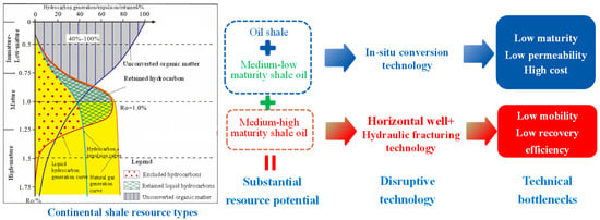
Figure 1.
Shale hydrocarbon generation, expulsion, and retained model and development status of organic-rich shale [1].
- (1)
- Shale Gas
Shale gas refers to natural gas stored in the pores, fractures, and kerogen networks of organic-rich shale, primarily in adsorbed (20–85%) and free states, with partial dissolution. According to EIA data (2023), the global technically recoverable shale gas reserves are approximately 134 trillion cubic meters, distributed primarily in North America (the United States and Canada), China, Argentina, Iran, and other regions. The United States has achieved the commercial development of shale gas, while China is the second-largest shale gas producer (with a production of over 260 billion cubic meters in 2023, mainly from the Sichuan Basin). Methane (CH4) dominates its composition. As shale gas mainly resides in nano-scale pores and micro-fractures, large-scale development can be achieved solely by enhancing reservoir conductivity through fracturing. Recent breakthroughs in horizontal well volume fracturing technology have increased shale gas recovery factors from 10% to 25%. While numerous researchers have contributed significantly to this advancement, detailed discussions are omitted here.
- (2)
- Medium-High Maturity Shale Oil
When shale maturity (Ro) ranges from 1.0% to 1.6%, kerogen pyrolysis produces liquid hydrocarbons, a portion of which remains trapped in shale, while the other migrates to adjacent sandstones, forming conventional reservoirs. Liquid hydrocarbons stored in organic-rich shale pores and kerogen are termed shale oil and are characterized by their high density, high wax content, and poor mobility. In 2015, the shale oil production in the Bakken and Eagle Ford oil areas was approximately 58.02 × 10⁶ tons and 72.84 × 10⁶ tons, respectively. In the Permian Basin, the shale oil production in the Wolfcamp and Spraberry oil areas was approximately 13.77 × 10⁶ tons and 29.50 × 10⁶ tons, respectively [2]. In 2019, the projected shale oil production in the United States was 9.6 million barrels per day (bbl/d) [3].The shale formations in the Western Canadian Basin host 42.36 billion barrels of crude oil, 5.86 billion barrels of condensate, and 3324 trillion cubic feet of natural gas. In 2013, Canada’s daily shale oil production reached 340,000 barrels, accounting for 9.7% of its domestic total oil production (3.52 million bbl/d) [4]. In 2014, Gazprom (Russia) carried out a tight oil appraisal well drilling project in the Krasnoleninsky Block of Western Siberia. Currently, Russia’s daily shale oil production is approximately 120,000 barrels, produced mainly in the Western Siberian Basin, which accounts for less than 1% of its total crude oil production [5]. In 2013, Lincoln Energy (Australia) announced the discovery of 23.3 billion barrels of shale oil resources in the Arckaringa Basin, but shale oil development in the country has progressed slowly [5].
Horizontal well volume fracturing technology has largely resolved large-scale development challenges for medium-high maturity shale oil resources in unconventional shale formations at mature–overmature stages (Ro > 1.0%) [1]. Field practices and laboratory data indicate recovery factors generally below 10% for such reservoirs. Thus, enhanced oil recovery (EOR) techniques are critical to unlocking the potential of shale resources. In conventional reservoir development, carbon dioxide (CO2) has proven effective as a flooding medium. The processing objective is to effectively mobilize the mobile crude oil in existing reservoirs through CO2 injection and other enhanced oil recovery (EOR) technologies.
- (3)
- Medium-Low Maturity Shale Oil
Medium-low maturity shale oil (0.5% < Ro < 1.0%) [6] has a retained hydrocarbon ratio exceeding 25%, with unconverted organic matter reaching 40% to 100% [1], rendering traditional “horizontal well + volume fracturing” ineffective. Conventional methods (e.g., water flooding and CO2 huff-and-puff) fail to displace adsorbed hydrocarbons, leaving resources stranded. Additionally, reservoirs exhibit weak natural energy (formation pressure coefficient < 1.2), with depletion development showing production decline rates of >30%. Conventional water/gas injection struggles to establish effective flooding pressure gradients. In situ conversion technology overcomes maturity limitations by artificially heating shale reservoirs to 350–500 °C, pyrolyzing solid organic matter and trapped hydrocarbons into small-molecule hydrocarbons underground, which are then produced via extraction techniques [7]. This approach represents a major industrial trend in shale oil development [1]. The processing objective is to artificially heat the reservoir through in situ conversion technology, promoting the pyrolysis of immature organic matter (kerogen) into light oil and gaseous hydrocarbons, thereby enhancing fluid mobility to achieve commercial extraction.
- (4)
- Oil Shale
Oil shale is an organic-rich sedimentary rock formed by the accumulation of organic matter in reducing environments and exists primarily in solid form. Kerogen, preserved in its original state without significant maturation (Ro < 0.5%), exhibits extremely high TOC levels (≥10 wt.%; typically 15–30%), classifying it as a “solid hydrocarbon source rock”. The global geological reserves of oil shale exceed 2 trillion tons, equivalent to approximately 280 billion tons of shale oil. These reserves are mainly distributed across the United States (50% of the global total), Russia, China, Brazil, and Estonia.
Oil shale can be exploited through surface pyrolysis, but this method poses significant environmental risks. Similarly to medium-low maturity shale oil, large-scale industrial development requires in situ methods. Artificial heating induces in situ kerogen pyrolysis into mobile hydrocarbons, enabling continuous extraction from the subsurface to the surface. Organic matter dominated by solid kerogen is converted into recoverable hydrocarbon fluids through in situ heating and pyrolysis. This approach avoids the environmental hazards of surface retorting, overcomes the limitations of shallow depth development, and enables large-scale and efficient development.
To address the core challenges in the development of different types of organic-rich shale (e.g., the recovery factor of medium-high maturity shale oil via horizontal well fracturing is less than 10%, medium-low maturity shale oil is difficult to exploit with conventional methods, and the surface retorting of oil shale is highly polluting and restricted), this paper identifies the current technical bottlenecks and points out the problem-oriented direction for subsequent targeted breakthroughs.
2. Exploitation Status of Medium-High Maturity Shale Oil
Experimental results indicate the primary recovery factor reaches only 10–15% of geological reserves [8], primarily due to significant volumes of crude oil existing in adsorbed–dissolved states within shale organic matter. Water flooding serves as the primary enhanced oil recovery method in conventional reservoirs but proves inapplicable to shale oil reservoirs due to clay swelling upon water contact, strong heterogeneity causing low sweep efficiency, and ultra-low permeability resulting in poor injectivity, which all hinder its implementation [9]. Consequently, some researchers propose CO2 injection to enhance shale oil recovery. CO2 injection for enhancing shale oil recovery offers dual advantages by mobilizing crude oil in adsorbed–miscible states within shale organic matter through its high affinity for organics, while also achieving efficient greenhouse gas sequestration in shale formations during injection.
Although CO2 injection in shale oil reservoirs is crucial for developing shale oil resources, current understanding remains unclear regarding oil flow mechanisms in organic-rich shale, interaction mechanisms among CO2, crude oil, and organic matter, as well as key differences between CO2-enhanced oil recovery in shale versus sandstone formations. Existing technical capabilities cannot yet support commercial CO2 injection in shale reservoirs. Some researchers have used numerical and molecular simulations to study fluid flow and adsorption behaviors in shale based on current knowledge; however, these models rely heavily on assumptions—such as perfectly smooth flow surfaces and relatively homogeneous porous media properties—that deviate significantly from actual reservoir conditions at both the macro- and micro-scales. Most results lack experimental validation. Due to the unique nature of shale oil reservoirs, obtaining reusable core samples is extremely difficult, leading to high operational challenges and low precision in laboratory experiments. Current experimental setups and methods cannot adequately investigate the aforementioned mechanisms. Therefore, novel testing techniques are needed to study oil flow behaviors in organic-rich shale and CO2–oil–organic matter interactions, analyze critical differences between CO2 flooding in shale and sandstone, and provide essential technical support for CO2-enhanced oil recovery in shale reservoirs.
2.1. Theoretical Basis of CO2 Injection Technology for Medium-High Maturity Shale Oil
Due to shale formations’ high complexity and heterogeneity, most shale oil is unextractable even with advanced horizontal well drilling and hydraulic fracturing [10,11]. The Bakken Formation’s shale oil recovery factor is 1–19% [12].
Simulation results show that shale oil reservoirs’ primary depletion recovery factor is only 6.5%; water flooding and gas injection increase it to 11.9% and ~15.1%, respectively [13]. Shale’s low permeability, porosity, high organic/clay content, and strong heterogeneity cause extremely low fluid conductivity, a core bottleneck in extraction [14,15].
Thus, studying fluid mobility is crucial for improving recovery. Existing studies show that shale oil includes free, adsorbed, and kerogen-dissolved oil [16]. MD simulation reveals alkane mobility in kerogen decreases with molecular weight [17]. Experiments show that adsorbed oil is more displaceable by CO2 and more mobile than dissolved oil [18].
This paper focuses on analyzing the occurrence and transport characteristics of alkanes for the following reasons: (1) alkanes are the main component of shale oil (accounting for 60–80% [19]) and their fluidity directly determines the development efficiency; (2) the differences in the molecular chain length of alkanes (C10–C20) have the most significant impact on the adsorption–diffusion behavior in nanopores, making them the core target of mobility regulation; (3) cycloalkanes and aromatic hydrocarbons have a relatively low content (approximately 15–30%) and their adsorption laws are similar to those of alkanes with the same carbon number [20]; and (4) unsaturated hydrocarbons are mainly generated in the late stage of high-temperature pyrolysis, with a content of <5 wt.%, and have a limited impact on the overall recovery factor.
Existing evaluation methods focus on two aspects [21]: (1) testing movable oil via vacuum imbibition and displacement experiments [16] and (2) analyzing movable oil via formation and flushed zone water saturation [22]. However, they only focus on free oil (regarded as movable oil) and ignore bound oil’s occurrence in nanopores, leading to obvious limitations.
To address nanopore structures’ restriction, as shown in Figure 2,our team combined nuclear magnetic resonance centrifugation and a variable-diameter capillary model, finding the following results: oil exists as free and irreducible states; bound oil (kerogen-adsorbed oil and nanopore (<100 nm) irreducible oil) is 1–2 orders of magnitude more than bound water, leading to <5% recovery due to strong adsorption.
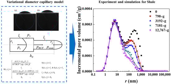
Figure 2.
Schematic diagram of the variational diameter capillary model and comparative of predicted versus experimental results (a. Shale 1, b. Shale 2) [23].
Our variable-diameter capillary model has a 92% consistency with the experiments, revealing bedding-dominated pore heterogeneity, quantifying the nanopore slip effect (improving mobility by 18–25%), and filling quantitative characterization gaps.
Furthermore, shale’s typical bedding structure is the main cause of reservoir heterogeneity and a key factor controlling fluid transport [24]. Core experiments show that laminated shale consists of clay–organic laminae and silty interbeds [25]; bedding characteristics affect exploration, drilling, and production, with nanopore seepage being particularly critical [26].
Molecular Dynamics Simulation (MDS) is widely used in nanopore fluid dynamics [27,28]. However, idealized carbon nanotube/quartz-based characterization leads to the introduction of numerical simulation in organic/inorganic nanopore transport studies [26,29]. Zhang et al. [26]’s apparent permeability model considers organic pore oil adsorption and inorganic pore interface slip, revealing enhanced adsorption/slip effects in sub-micron pores (<100 nm) with reduced pore size.
Based on the above studies, shale crude oil exists in free (pores), adsorbed (organic surfaces), and dissolved (organic matter) states [16,24,30]. Experimental data show that organic alkanes account for 6–55 wt.% of total content; CO2 displacement experiments confirm that adsorbed alkanes are harder to displace than dissolved ones [24]. Shale pore volume correlates positively with thermal maturity [31], so Darcy’s law is limited in low-maturity organic transport (diffusion should be emphasized). No systematic academic understanding of bedding’s regulatory role in oil–gas seepage exists yet.
To address this gap, COMSOL Multiphysics (6.2) was used to simulate alkane transport in laminated shale. As shown in Figure 3,our team developed the first model integrating viscous flow, surface adsorption, and organic diffusion, finding the adsorbed phase saturation to be 2.2–8.3% and the dissolved phase to be 41.8–51.4%, with the equilibrium time diffusion dominated. Bedding characteristics (e.g., porosity) regulate oil distribution: a larger S results in a smaller d, and higher Fab shortens equilibrium time. Ds accelerates dissolution but is weaker than Dd; increased Ds, Dd, kads, and kabs promote migration, filling the adsorption–diffusion coupling gap and supporting CO2 displacement technology.
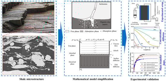
Figure 3.
Experimental setup for alkane transport in laminated shale with corresponding model and results [32].
However, research on bedding’s collaborative control of oil phase distribution and transport pathways across scales (nanopores and micro/macro-fractures) is insufficient. Via integrating extended Fick’s law with a Darcy–Fick model, adsorption–diffusion–seepage coupling experiments under variable temperature/pressure can establish a unified multi-physical field characterization system for low-thermal-maturity reservoirs.
Notably, much shale crude oil exists in adsorbed–miscible state in organic matter; thus, improving its production is a core scientific issue in shale oil development [33,34].
Under reservoir conditions, CO2 is dissolved in crude oil, so CO2 and crude oil adsorption in organic matter is a two-component liquid–solid adsorption phenomenon.
As shown in Table 1,Common liquid–solid two-phase adsorption models [35] are (1) NBP~na (non-ideal surface/free phases and surface phase unaffected by free phase); (2) NBP~a (non-ideal phases and surface phase affected by free phase) [36]; (3) IAP (ideal surface and non-ideal free phase) [37]; and (4) IBP (ideal both phases). All assume homogeneous adsorbent surfaces, but experiments [38,39,40] show they poorly fit some adsorption curves, mainly due to inhomogeneous adsorbent surfaces.

Table 1.
Comparative table of liquid–solid two-phase adsorption models.
Molecular simulation (e.g., the MC method) aids multi-component adsorption research. Kerstin Falk [17] found that longer alkane chains reduce accessible kerogen pores; Rosenbach et al. [41] found that hydrocarbon adsorption reduces some pore sizes in porous media.
A key research gap remains, pertaining to the unclear interaction mechanism between CO2 and alkanes in shale organic matter, and competitive adsorption–dissolution laws.
As shown in Figure 4, our team first quantified CO2’s displacement effect on alkanes: CO2’s adsorption state displacement capacity is significantly higher than that of its dissolved state (the latter needs a critical CO2 concentration), with its efficiency decreasing exponentially with the carbon chain length. A temperature rise reduces the dissolution rate by 12–18 wt.% (low temp/high pressure is optimal); a pressure rise increases adsorption/dissolution by 20–35 wt.% but weakens dissolved state displacement due to intensified pore competition. We verified the “adsorption priority” law via multi-medium experiments, filling the gap in multi-phase displacement kinetics quantification and laying a foundation for gas injection parameter optimization.
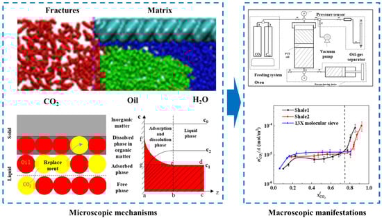
Figure 4.
Microscopic mechanism of CO2–shale oil competitive adsorption–dissolution with experimental setup and results [18].
2.2. CO2 Huff-And-Puff Technology for Enhancing Shale Oil Reservoir Recovery
CO2 injection effectively reduces crude oil viscosity and oil–water interfacial tension in reservoirs [42], demonstrating superior recovery enhancement compared to nitrogen flooding. This technology significantly improves near-wellbore permeability by dissolving formation minerals through carbonate dissolution [43]. Field tests by Schenewerk et al. [44], in South Louisiana, confirmed that CO2 huff-and-puff can reconstruct reservoir fluid saturation fields and reduce the produced water cut. Hawthorne et al. [45] conducted dynamic displacement experiments using Bakken shale samples under supercritical CO2 conditions (5000 psi; 110 °C), systematically investigating supercritical CO2 extraction effects on shale oil. The experimental data show that 90 wt.% of crude oil can be extracted from shale samples within 4 h.
The complex fracture networks in shale reservoirs effectively increase the CO2–crude oil contact area and provide preferential pathways for oil migration into fracture systems [46]. Chen et al. [13] systematically studied heterogeneity impacts on CO2 huff-and-puff recovery using the UT-COMP numerical platform, finding that reservoir heterogeneity reduces production rates and ultimate recovery. Zhu et al. [47] investigated fracture property effects on CO2-enhanced shale oil recovery. The results indicated that reduced hydraulic fracture spacing improves pre-breakthrough oil production but causes significant post-breakthrough decline and a lower ultimate recovery. Ozotta et al. [48] found that ScCO2 can alter the mechanical properties and mineral composition of shale, promoting the expansion of fractures. Ao et al. [49] indicated that prolonged contact between ScCO2 and shale can lead to a decrease in shale strength and alter its mineral composition. Yin et al. [50] studied the effects of ScCO2 and subcritical CO2 on the mechanical performance of organic-rich shale at 38 °C and found that they can significantly alter the fracture propagation process and mechanical characteristics of shale.
The mechanism of action of CO2 in shale oil reservoirs is highly complex. The research on enhancing the recovery factor of shale oil reservoirs through CO2 injection is still in its early stages. Besides the miscible extraction of CO2 and hydrocarbon fluids, it also involves multiple physicochemical processes such as the diffusion, adsorption, and reverse displacement of CO2 in organic matter. Existing theoretical models do not take into account the interactions among CO2, hydrocarbon fluids, and organic matter, and thus cannot accurately describe the diffusion and displacement processes of CO2 in organic matter. Due to the differences between liquid hydrocarbon molecules and gaseous hydrocarbon molecules, the adsorption behavior of CO2 in shale oil reservoirs is more complex. There is a lack of experimental results regarding the interaction between shale oil rock samples and CO2, and none of the existing theoretical models can accurately describe the mechanism of action of CO2 in shale oil reservoirs. Ultimate oil recovery after miscible CO2 flooding: 80.9%, 70.7%, 64.7%. Water flooding: produced oil (C5–C16 > C17–C27), remaining oil (cluster/network > films). CO2 flooding: gas (CO2, CH4), oil’s C5–C16 up [51].Addressing the challenge of uncertain CO2 huff-and-puff adaptability, as shown in Figure 5, our team’s fractured reservoir experiments reveal distinct recovery differences between shale and sandstone; alkanes where shale exhibits 15–25 wt.% lower the recovery efficiency per cycle but maintain a multi-cycle decline rate of below 5%/cycle, differing from the rate of over 12%/cycle for sandstone, requiring at least five cycles to achieve cumulative advantages with 30–40 wt.% enhancement. Increasing injection pressure to miscibility pressure such as 8 → 12 MPa elevates the recovery efficiency by 50–70 wt.%, with the optimal pressure near to the minimum miscibility pressure (MMP). Shale demands 20–35 wt.% higher injection volumes and 1.5–2 times longer injection durations. Fracture systems show low sensitivity with fluctuations under 3% and rapid diffusion featuring 60–80 wt.% shorter equilibrium times, governed primarily by CO2–crude oil interactions within the matrix. This quantifies shale–sandstone recovery differences and fills dynamic prediction theory gaps.
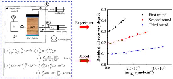
Figure 5.
Mathematical model for CO2 transport in shale reservoirs with experimental setup and results [52].
There is currently a lack of quantitative analysis on reservoir permeability evolution, fracture conductivity degradation, and adsorption–desorption equilibrium dynamics following repeated CO2 injection. Future work should develop multiphysics models that couple chemical reactions (e.g., CO2–mineral dissolution/precipitation) with fluid flow to predict long-term reservoir permeability trends, and should establish an intelligent analysis (IA) model to evaluate the impact of CO2 huff-and-puff processes on rock stability.
2.3. CO2 Miscible Flooding Technology for Enhancing Shale Oil Reservoir Recovery
CO2 flooding represents the most effective technique for enhancing shale oil recovery [9,53,54]. When the injection pressure exceeds the minimum miscible pressure (MMP), CO2 forms a miscible system with crude oil [55], significantly improving recovery. Compared to N2 and CH4, CO2 achieves miscibility more readily [56]. Miscible flooding overcomes the sweep limitations of huff-and-puff by achieving zero interfacial tension, enabling full-field displacement.
Based on the competitive adsorption between CO2 and hydrocarbons, the adsorbed and dissolved hydrocarbons in shale can be displaced by CO2 [24,57]. Wang et al. [58] confirmed through methane adsorption experiments on 110–120 mesh shale particles that adsorption equilibrium exceeds 10 min under high pressure (15 MPa). Coupling exists between micropore/surface diffusion and adsorption–dissolution processes. Thus, scholars propose using the total adsorption rate to characterize three key processes, including micropore surface diffusion, surface adsorption, and intra-organic dissolution [59].
In low-permeability reservoirs, molecular diffusion critically influences CO2 miscible flooding [60]. Existing studies validate Fick’s law for describing CO2 diffusion in dilute solutions (mole fraction < 10%). However, during miscible flooding, CO2 mole fraction variations exceed 90%, where friction effects and solid–liquid interactions intensify significantly in concentrated systems [61], causing substantial deviations in Fick’s law predictions. Researchers thus developed diffusion models for concentrated systems based on Maxwell–Stefan (MS) equations [62]. This framework successfully applies to gas/liquid diffusion, porous media mass transfer, and polymer system transport [61].
While CO2 miscible flooding proves to be the most effective method for exploiting oil in blind-end pores. In porous media, CO2 miscible flooding successfully mitigates fingering phenomena and efficiently recovers crude oil located at blind end and corner regions of the pores. The recovery efficiency achieved through CO2 miscible flooding is approximately 30% higher than that of water flooding and about 10% greater than that achieved through CO2 immiscible flooding [63].
High injection pressure and injected PV increased the oil-in-shale flow performance and enhanced the shale oil recovery in CO2 flooding to a certain extent [64]. Fakher and Imqam conducted CO2 flooding experiments using combined nanocomposite filter membranes in an experiment vessel to study the impacts of CO2 injection pressure, temperature, and oil viscosity on oil recovery. They found that increasing experimental pressure and temperature enhanced oil recovery [65]. CO2 immiscible flooding is suitable for the development of low-viscosity crude oil (<50 mPa s), especially for an oil viscosity of less than 10 mPa. CO2 miscible flooding is advisable for low-permeability and medium- and high-permeability reservoirs, especially for reservoir permeability of higher than 10 mD. Above the MMP, the oil recovery factor is over 85% and the increase rate slows down with pressure; CO2 miscible flooding is preferred for the high-pressure reservoir [66].
Currently, experimental methods can effectively determine the static adsorption and dissolution amounts of hydrocarbons in shale organic matter; however, the real-time monitoring of the dynamic adsorption and dissolution amounts during the CO2 miscible flooding process still faces technical bottlenecks.
Addressing the technical challenges in the real-time monitoring of dynamic adsorption-dissolution during CO2 miscible flooding, as shown in Figure 6, our team coupled NMR technology with mathematical models to reveal multi-stage mechanisms where adsorbed–miscible oil exhibits a 40–60% lower recovery efficiency than free oil. The flooding process comprises three stages, including Stage I, featuring the rapid displacement of interlayer free oil, Stage II, with synergistic displacement, and Stage III, involving the slow mobilization of residual adsorbed oil and accounting for 60–80% of the total cycle. Increased sandstone interlayer proportion enhances Stage I efficiency but inhibits Stages II–III. Elevated adsorption displacement thresholds shorten Stage II while prolonging Stage III, with adsorption rate constants govern Stage III recovery efficiency. This work fills quantitative gaps in CO2 miscible flooding stage division and parametric sensitivity analysis.
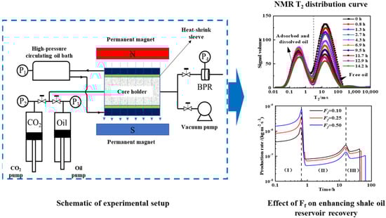
Figure 6.
Experimental setup for CO2 miscible flooding to enhance shale oil recovery factor with experimental results [67].
For future CO2 flooding technology, research should prioritize carbon storage. Developing intelligent injection–production systems using nanofluids (e.g., surface-modified SiO2) to control the CO2 mobility ratio could simultaneously enhance oil displacement efficiency and mineralization storage. Optimizing supercritical CO2 (ScCO2) injection parameters to form stable gas caps for structural storage at reservoir tops while driving crude oil and promoting dissolution storage at the base is essential.
3. Exploitation Status of Medium-Low Maturity Shale Oil and Oil Shale Underground Conversion
Based on distinct heat sources and heat transfer mechanisms, four technical approaches exist for the in situ extraction of medium-low maturity shale oil and oil shale, including conductive heating, convective heating, radiative heating, and reactive heating [68]. Conductive heating and reactive heating technologies are relatively mature, both having undergone pilot field tests with produced crude oil [69].
Unlike the aforementioned physical heating methods, reactive heating technology primarily utilizes heat generated by reactions between oxygen and residues from kerogen pyrolysis to heat adjacent formations, supplemented by minimal auxiliary heat injection depending on geological conditions [70]. According to localized reaction intensity, reactive heating can be classified into underground combustion heating and the autothermic pyrolysis in situ conversion process (localized chemical reaction method, TS). Autothermic pyrolysis in situ conversion process represents an efficient thermal pyrolysis method enhanced by chemical heating [7]. Compared to underground combustion heating, the autothermic pyrolysis in situ conversion process exhibits a weaker oxidation intensity, reducing heat waste from reactions involving high-quality oil/gas and inorganic matter while lowering operational complexity for subsurface reaction control. It is thus an efficient in situ extraction technology for oil shale [7].
3.1. Theoretical Basis of In Situ Conversion Technology for Medium-Low Maturity Shale Oil and Oil Shale
3.1.1. High-Temperature Evolution Characteristics of Pore Structures in Organic-Rich Shale
Organic-rich shale, as a heterogeneous tight sedimentary rock abundant in organic matter [71], exhibits extremely low original porosity, poor pore connectivity, and ultra-low permeability. During in situ high-temperature pyrolysis, kerogen cracking generates hydrocarbons, while secondary pores and fractures develop within the solid matrix, serving as migration pathways that enhance hydrocarbon transport capacity. Therefore, the quantitative and qualitative characterization of pores and fractures in organic-rich shale is crucial for reservoir development.
Current mainstream pore characterization techniques comprise three categories, including microscopic imaging, fluid saturation methods, and nuclear magnetic resonance (NMR) technology.
Micro–nano CT (also termed micro-CT) employs micro/nano-focus X-ray sources to achieve micron or sub-micron resolution, representing a non-destructive 3D imaging technique [72]. Saif et al. [73] utilized time-resolved X-ray micro-tomography with synchrotron radiation for dynamic imaging, capturing the 4D (3D + real-time) evolution of fracture initiation, propagation, coalescence, and closure. Rabbani et al. [74] analyzed CT images of thermally decomposed shale samples to optimize transport pore modeling for petroleum production, but overlooked the characterization of kerogen, a critical shale component. Huang et al. [75] proposed a three-phase segmentation method (pores, kerogen, and matrix) beyond traditional two-phase segmentation, analyzing kerogen content evolution during pyrolysis.
Suekuni et al. [76] demonstrated increasing kerogen skeleton density in organic-rich shale with rising maturity, while Vasileiadis et al. [77] reported decreasing kerogen relative density at elevated pyrolysis temperatures. Shi et al. [78] attempted the molecular modeling of kerogen in organic-rich shale, collectively substantiating intra-kerogen organic pore development during pyrolysis.
The resolution of existing CT (e.g., micro–nano CT) characterization methods is insufficient to cover the size range of the large number of mesopores and micropores in kerogen. This means that although the existence of such tiny pores has been confirmed, they cannot be effectively identified or quantified by this technology. Furthermore, it creates “blind spots” in the understanding of kerogen’s pore structure and fails to fully reveal the actual distribution and development characteristics of its internal pores.
To address the limitations in precise kerogen characterization and traditional three-phase segmentation, as shown in Figure 7, our team employed micro–nano CT three-phase segmentation to quantify organic–inorganic pore–kerogen cluster co-evolution mechanisms. Inorganic porosity increased stepwise with temperature (200–800 °C: 3% → 15.4%), dominated by three stages (kerogen pyrolysis, clay decomposition, and carbonate dissolution). Bedding fractures increased the fractal dimension by >50% at 400 °C. Kerogen clusters exhibited drastic mass reduction at 300–400 °C (volume fraction: 25% → 12.5%), with organic porosity reaching 7–8% and skeleton density rising from 1.15 to 1.54 g/cm3, reflecting the pore generation–densification equilibrium. Dispersed kerogen (30% proportion) showed a higher pyrolysis yield, with the storage coefficient decreasing >60% at 200–400 °C, confirming its efficacy as high-efficiency hydrocarbon source. A multiscale theoretical framework for high-temperature shale pore evolution was established, elucidating pore–pyrolysis coupling pathways and filling quantitative characterization gaps for in situ converted reservoirs.
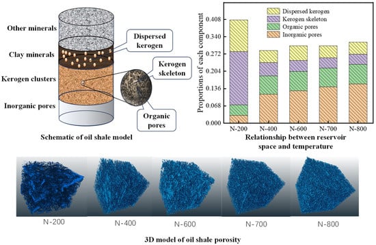
Figure 7.
Schematic and 3D model of oil shale porosity; relationship between reservoir space and temperature [79].
Artificial intelligence demonstrates revolutionary potential in pore identification and quantitative characterization of organic-rich shale. Future breakthroughs may include integrating deep learning with generative adversarial networks (GANs) for the super-resolution reconstruction of micro–nano CT images, overcoming physical resolution limits to identify/quantify nano-scale organic pores (<2 nm), and developing 3D convolutional neural network (3D-CNN) intelligent segmentation algorithms for fully automated four-phase (or more) segmentation of shale pores, kerogen (skeleton + organic pores), and inorganic matrix.
3.1.2. Convective Heat Transfer Mechanisms in Stimulated Shale Reservoirs
In in situ conversion technologies, convective heating and reactive heating attract significant attention due to rapid heating rates and scalability. However, these processes require reservoir stimulation to enhance fluid injectivity and sweep efficiency in shale formations. Stimulated shale reservoirs exhibit strong heterogeneity, and in situ conversion requires maintaining high-temperature fields (typically >350 °C, exceeding 1000 °C in some processes) [80]. Thus, accurately characterizing such convective heat transfer is critical for designing efficient in situ conversion schemes and predicting performance.
Fractured reservoir numerical simulation primarily employs three mathematical models, including the discrete fracture model (DFM), equivalent continuum model, and dual media model. The dual media model is the most mature and has been integrated into commercial simulators like CMG [81] and Eclipse [82,83]. This model treats fractures and matrix as two independent continua, idealizing connected fracture systems and matrix systems as spatially overlapping entities. The Warren–Root model [84,85] simplifies matrix flow by that assuming fluid within matrix blocks can only flow into fractures—termed thermal channeling—whose intensity depends primarily on the shape factor [86]. This model typically applies only when fracture permeability significantly exceeds matrix permeability, allowing fluid flow to wells via fractures. For formations with smaller fracture-matrix permeability contrast, Deruyck et al. [87] proposed a dual-porosity, dual-permeability (DPDP) model accounting for intra-matrix flow, where matrix-stored fluids can enter wells either through fractures or directly via the matrix. Hill et al. [88] further developed a compositional DPDP model incorporating oil, gas, and water phases.
Traditional convective heat transfer dual media models are primarily designed for highly heterogeneous, high-permeability formations (such as heavy oil thermal recovery and oil sands development [89]). In tight shale formations, however, the low matrix permeability results in slow heat exchange between fractures and the matrix, and the dominant mechanism for this heat exchange is thermal channeling between fractures and the matrix—an aspect that has not been accounted for in the aforementioned models.
To address the underestimated heat exchange rates in traditional dual media models for fractured tight shale, as shown in Figure 8, our team developed the first dual-porosity, dual-permeability model incorporating coupled fluid-channeling and thermal-channeling effects. The enhanced model separates fluid-channeling heat transport (>70% contribution) from thermal-channeling effects (4.81 × heat transfer acceleration), achieving R2 > 0.95 accuracy during pseudo-steady state. Thermal channeling dominates (>95%) when the matrix permeability is <0.001 mD, diminishing to <10% at permeabilities >0.01 mD. Heat transfer increases by >300% when fracture spacing is <180 cm, while widening fractures (0.1 → 1 mm) enhance the fluid-channeling contribution by 40%. This resolves traditional models’ heat transfer inaccuracies and fills the theoretical gaps in stimulated reservoir thermal simulation. Although the embedded discrete fracture model (EDFM) precisely describes fracture–matrix interactions, its prohibitive computational cost and meshing complexity hinder practical field applications requiring rapid simulation.
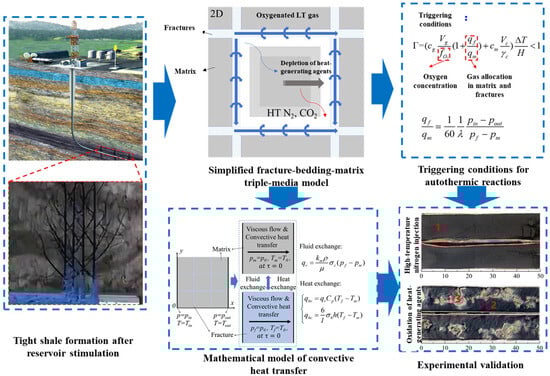
Figure 8.
Convective heat transfer and triple media model with experimental validation (1. carbon residue, 2. inorganic matter. 3, partially oxidized carbon residue) [90].
Although the embedded discrete fracture model (EDFM) precisely describes fracture–matrix interactions, its prohibitive computational cost and meshing complexity hinder practical field applications requiring rapid simulation. The real-time monitoring of fracture network propagation and secondary pore formation during pyrolysis remains challenging via conventional methods (e.g., micro–nano CT). Current techniques rely on offline experiments or static imaging, unable to dynamically track fracture connectivity evolution, pore development, or fluid migration pathways during pyrolysis. Dynamic pyrolysis process models can be established based on field data.
3.1.3. Oxidative Pyrolysis Reaction Mechanisms of Organic-Rich Shale
Studies indicate that injecting appropriate oxygen-containing gases into formations enables the oxidative pyrolysis of kerogen or its residues to release heat, effectively reducing external energy input while sustaining continuous kerogen pyrolysis reactions [71,91,92,93,94,95,96,97,98,99,100,101,102,103,104]. The comparative analysis of pyrolysis products under oxidative versus inert conditions confirms comparable shale oil yields in oxygen-containing atmospheres [95,105], with oxygen even promoting the generation of light hydrocarbon fractions [106]. Guo et al. [91] and Guo et al. [98] propose that oxygen participation alters organic matter pyrolysis pathways and facilitates cracking at lower temperatures.
Understanding this complex physicochemical process requires the clarification of oxygen reaction pathways and organic matter transformation mechanisms [107]. Thermogravimetry/differential thermogravimetry (TG/DTG) and differential scanning calorimetry (DSC) analyses of various organic-rich shales reveal three distinct peaks during oxidative pyrolysis. Based on the peak characteristics, researchers classify the process into low-temperature oxidation (LTO) [108,109], medium-temperature oxidation (MTO), and high-temperature oxidation (HTO), inferring multi-stage parallel reactions. Accordingly, Wang et al. [104] established a mechanistic model for the oxidative retorting of Huadian organic-rich shale. Khakaimova et al. [97] developed numerical models for Bazhenov shale oxidative pyrolysis in low-(LTR) and high-temperature regions (HTR), demonstrating the temperature-dependent reactions of kerogen and its oxidized products.
Although oxidative pyrolysis shows a strong correlation with temperature, the cyclic temperature characteristics in existing studies are derived from linear heating conditions, leading to insufficient understandings of isothermal reaction characteristics. Furthermore, in actual oxidative pyrolysis processes, exothermic oxidation and endothermic pyrolysis coexist, which causes continuous temperature fluctuations. Current experiments often ignore the discrepancies between setpoint temperatures and actual temperatures; meanwhile, fixed short reaction times result in incomplete organic carbon conversion under low-temperature conditions, thereby hindering the accurate determination of transformation pathways.
Addressing uncertainties regarding oxidative pyrolysis characteristics under isothermal conditions and experimental–actual temperature discrepancies, as shown in Figure 9, our team developed a temperature-dependent kinetic model through multi-technique experiments, revealing a two-stage mechanism for organic-rich shale where low-temperature oxidative pyrolysis LTOP (<340 °C) primarily involves kerogen oxidation with the CO2/CO release exceeding 85% without hydrocarbon generation, and where high-temperature oxidative pyrolysis HTOP (>340 °C) is dominated by pyrolysis yielding a 3–5 times higher shale oil production and hydrocarbon gases that constitute 30–45%. The staged model shows that LTOP follows oxygen addition–bond cleavage reactions increasing the residual carbon oxidation degree by 40–60%, whereas HTOP exhibits pyrolysis–oxidation synergy with pyrolysis contributing over 70%, featuring triphasic rate evolution in HTOP (peak rate 0.8%/min) versus the monotonic decline in LTOP. High-grade shales (TOC > 15 wt.%) exhibit higher reaction intensity with 15–20 wt.% greater total weight loss, 20–30 °C elevated HTOP critical temperature, and 0.2–0.3 higher H/C ratios in shale oil. This resolves thermal–oxygen synergy mechanisms and fills quantitative gaps in oxidative pyrolysis kinetics characterization.
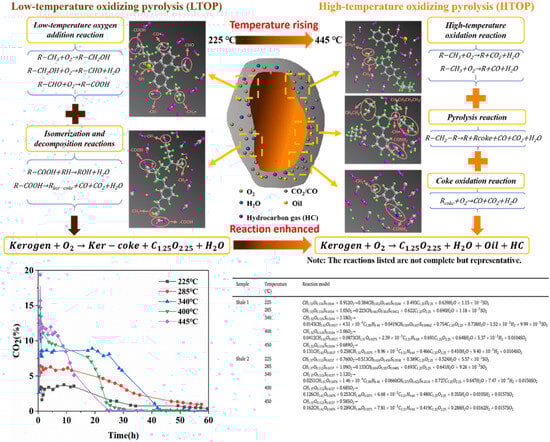
Figure 9.
Comparison of high- and low-temperature oxidative pyrolysis models for organic-rich shale [110].
Current studies predominantly focus on oxygen concentrations or temperature ranges, lacking an analysis of the combined effects from oxygen gradients (e.g., 0.5–10% O2) and thermal fluctuations (e.g., actual reservoir thermal fields). Additionally, achieving uniform oxygen distribution and effective diffusion in tight shale reservoirs remains a critical engineering challenge to prevent localized overheating or oxygen-depleted zones.
3.2. Autothermic Pyrolysis In Situ Conversion Process
In situ conversion technologies have been studied for years, yet conventional approaches rely on single heating mechanisms requiring substantial external energy, exhibiting slow heating rates, prolonged duration, and low efficiency [111,112], while neglecting shale’s inherent geothermal potential [102,113].
The autothermic pyrolysis in situ conversion process (ATS) is triggered by injecting room-temperature oxygen-containing gases into locally preheated formations [114]. Compared to underground combustion, ATS features milder oxidation, reducing heat waste from oil/gas inorganic reactions. Bai et al. [115] laboratory tested ATS by sequentially injecting 300 °C and 25 °C air into oil shale blocks. Guo et al. [93] identified the oxidation of pyrolysis residues as the primary heat source. Sun et al. [91] determined that residual carbon oxidation provides most heat via elemental analysis. Peng et al. [100] observed minimal oil yield differences between oxidative and anaerobic retorting. However, these experiments used granular samples without considering overburden pressure or heat loss. Wang et al. [108] found that residual carbon accounts for 35% of shale’s total calorific value. Despite substantial oxidation heat in ATS, significant heat dissipates through fluid phase changes and non-target zones. Zhang et al. [116] highlighted the critical impact of gas injection rates and oil content on thermal front propagation. Beyond lab studies, a 2016 field test in Songliao Basin aimed to advance ATS commercialization [117], yet yielded only 1.68 tons over three months. Guo et al. [118] attributed low recovery to reservoir containment issues. While proving technical feasibility, the project’s energy efficiency fell below economic thresholds.
Currently, the reaction mechanism and heat source of the autothermic pyrolysis in situ conversion process are fundamentally understood; however, existing research findings are predominantly derived from particle sample tests under atmospheric pressure, which differ from actual formation conditions. During the autothermic pyrolysis in situ conversion process in shale formations, kerogen pyrolysis can induce significant alterations in the two-phase seepage characteristics of the formation, thereby influencing the heat supply efficiency of the self-heating reaction and potentially leading to the interruption of the extraction process. Therefore, it is essential to quantitatively characterize the dynamic evolution of heat supply efficiency during the autothermic pyrolysis in situ conversion process in shale formations, thereby obtaining methods for the dynamic optimization and control of self-heating reactions.
To address uncertainties in ATS feasibility, stability, and energy efficiency under reservoir conditions, as shown in Figure 10, our team’s experimental studies have demonstrated that 300 °C triggering achieves autothermal cracking (peak 600 °C), with 67.1 wt.% oil recovery at low oxygen injection (O2 < 5%) and 85% energy reduction versus nitrogen injection (HNICP). A five-zone reaction model (residue/autothermal/cracking/preheat/virgin rock) reveals dual regulation of permeability (reduced by 40–60%) and thermal sweep coefficient (increased by 20–30%) by heavy component deposition. ATS yields 15–20 wt.% more light fractions than HNICP, with the H/C ratio ↑0.1–0.2 and an energy efficiency of 3.46 (seven times higher than HNICP). This confirms ATS’ technical feasibility and establishes its high-efficiency status.
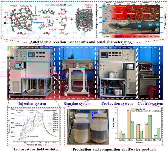
Figure 10.
Experimental setup for autothermic in situ conversion with reaction zone characteristics and experimental results [104].
However, the excessive intensity of the autothermic pyrolysis in situ conversion process requires efficient control to prevent oil loss while enhancing thermal sweep efficiency. Implementing a graded oxygen injection strategy— by dynamically adjusting the oxygen concentration based on thermal feedback (e.g., reducing to O2 < 3% in high-temperature zones and increasing to 5–8% in low-temperature zones)—avoids localized over-oxidation and thermal runaway. Alternatively, injecting transition metal oxide nanoparticles promotes low-temperature oxidation (<300 °C) while suppressing high-temperature coking reactions, lowering peak reaction temperatures from 600 °C to 450–500 °C. Thermal sweep enhancement can be achieved through staged fracturing technology that constructs a “main fractures + micro-fractures” composite system to expand the thermal contact area and accelerate lateral heat transfer, or by reinjecting the CO2 generated from oxidation into low-temperature zones. Leveraging its supercritical state high diffusivity, the reinjected CO2 carries heat to drive thermal front propagation toward distal regions.
3.3. Hybrid Natural Gas-Assisted Autothermic Pyrolysis In Situ Conversion Process
For medium-low-oil-content organic-rich shale formations (oil content < 5.0%), insufficient heat-generating agents from kerogen pyrolysis hinder the successful triggering or sustained progression of ATS technology [119]. Given that such formations are globally widespread, representing over half of the organic-rich shale resources, cost-effective development is crucial for efficient resource utilization. Theoretically, the auxiliary injection of minimal natural gas could address this heat deficit by utilizing oxidation-derived heat to supplement formation heating.
Numerical simulation studies on the in situ conversion of organic-rich shale are well-established. Fan et al. [120] employed Stanford’s GPRS framework for the reservoir simulation of in situ upgrading, revealing strong correlations between hydrocarbon production and heating temperature. Guo et al. [121] developed a numerical model for ATS development, elucidating thermo-hydro-chemical coupling mechanisms and systematically evaluating how preheating temperature, O2 concentration, and gas injection rate regulate oil recovery and energy return efficiency.
To resolve the issue of insufficient heat generation impeding ATS in medium-low-oil-content formations, as shown in Figure 11, our team innovatively established a co-optimization model for natural gas mixing ratios and energy efficiency. This reveals the differential enhancement mechanisms of the hybrid natural-gas-assisted autothermic pyrolysis in situ conversion process (H-ATS). Low-oil-content reservoirs require minimal gas mixing (optimal 2.0%) for self-sustained heating, achieving an energy return ratio of 3.70. Medium-high-oil-content reservoirs achieve 19.19–29.47% higher energy return ratios but incur 6.62–8.22 wt.% reductions in oil yield. This resolves uncertainties in the adaptability of the multi-energy coupling process, quantifies the mixing effects on energy efficiency and productivity, and establishes a theoretical foundation for the graded optimization of shale’s in situ conversion.
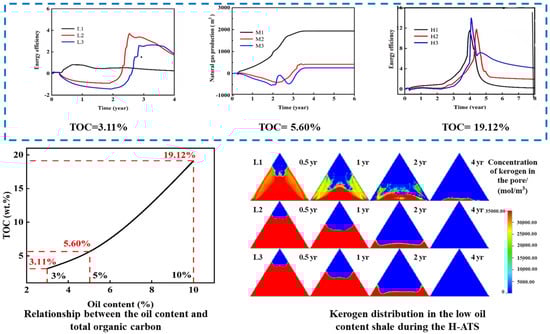
Figure 11.
Energy return ratio in H-ATS formations with low/medium/high oil content; kerogen distribution in low oil-content shale [122].
For medium-low-maturity shale oil and oil shale resources, in situ conversion results in oil yield decreasing significantly under high-pressure conditions, exceeding a 60 wt.% reduction. Studies indicate that CO2 injection enhances oil yield. Future research should explore utilizing CO2 generated during kerogen oxidative pyrolysis, which can be pressurized and reinjected into formations. This approach aims to improve crude oil recovery while achieving carbon sequestration objectives, potentially providing a novel approach for green development of medium-low maturity shale oil.
4. Conclusions
This study focuses on the efficient and green development of organic-rich shale, addressing two major challenges: low recovery in medium-high maturity shale oil and high energy consumption in the in situ conversion of medium-low maturity shale/oil shale. Through theoretical modeling and experimental research, four key breakthroughs were achieved, establishing a maturity-adapted green development system.
As shown in Table 2, theoretically, a CO2–hydrocarbon competitive adsorption and fluid transport theory was established. Our team achieved the precise differentiation of multi-state hydrocarbons for the first time, clarified the CO2 displacement advantage, and developed a laminated shale transport model revealing non-Darcy flow mechanisms. Technologically, CO2 flooding techniques were improved, with huff-n-puff and miscible flooding increasing recovery rates to 60 wt.% and 90 wt.%, respectively. The autothermic pyrolysis in situ conversion process (ATS) technology reduced energy consumption by 85%, while the natural-gas-assisted technology (H-ATS) achieved an energy return ratio of 3.70.
Table 2.
Critical analysis and comparison table of main exploitation technologies for organic-rich shale.
Future work will focus on the following: developing multi-field coupling theories, advancing graded oxygen injection coupled with nanocatalysts, establishing a shale development–CCUS–new energy–multi-energy complementarity model, and boosting the localization rates of core equipment beyond 90%.
Addressing the fragmentation of existing research, this paper accurately identifies three core research gaps and integrates corresponding solutions: first, the “stage division” of CO2 flooding for medium-high maturity shale oil (rapid displacement of free oil–synergistic displacement–mobilization of residual adsorbed oil), with clarification of the dominant factors for each stage; second, the “thermal–oxygen synergistic mechanism” of in situ conversion for low-medium maturity shale/oil shale (staged characteristics of low-temperature oxidation–high-temperature pyrolysis), with the quantification of the reaction efficiency at different temperatures; third, the development adaptability of low oil content resources (<5%), with proposal of the optimal parameters for the hybrid natural-gas-assisted autothermic pyrolysis in situ conversion process (H-ATS), thus providing a clear problem–solution correspondence for the industry.
Through this “theory–technology–environment” integrated system, this study achieves dual breakthroughs in enhanced recovery and reduced energy consumption, providing a viable pathway for low-carbon development of shale resources.
Author Contributions
M.W.: Conceptualization, Methodology, Writing-Original draft preparation, Validation, Supervision, Investigation. L.Y.: Validation, Writing-Reviewing and Editing, Supervision, Investigation. H.Z.: Validation, Writing-Reviewing and Editing, Supervision, Investigation. Y.W.: Validation, Writing-Reviewing and Editing, Supervision, Investigation. C.Z.: Idea, Conceptualization, Funding acquisition. All authors have read and agreed to the published version of the manuscript.
Funding
We acknowledge the financial support offered by the National Key R&D Program of China (Grant No. 2019YFA0705502, Grant No. 2019YFA0705501), the National Oil Shale Exploitation R&D Center Open Fund Project (Grant No. 33550000-24-ZC0613-0055), and the Key R&D projects of Jilin Provincial Science and Technology Department (Grant No. 20230203121SF).
Data Availability Statement
No new data were created or analyzed in this study.
Conflicts of Interest
Author Lihong Yang, Hao Zeng was employed by the company Sinopec Petroleum Exploration & Production Research Institute. The remaining authors declare that the research was conducted in the absence of any commercial or financial relationships that could be construed as a potential conflict of interest.
References
- Zhao, W.Z.; Hu, S.Y.; Hou, L.H. Connotation and strategic role of in-situ conversion processing of shale oil underground in the onshore China. Pet. Explor. Dev. 2018, 45, 537–545. [Google Scholar] [CrossRef]
- EIA. World Shale Resource Assessments 2015. Available online: http://www.eia.gov/analysis/studies/worldshalegas/ (accessed on 1 December 2015).
- Chen, X. Advances in the research on the occurrence state and resources assessment of shale oil. Sci. Technol. Eng. 2017, 17, 141–149. [Google Scholar]
- Qu, H.; Yang, X.; Cao, J.; Fan, Y. Oil accumulation rules in deep zones of Upper Triassic Yanchang Formation in Ordos Basin. Act A Pet. Sin. 2011, 32, 243–248. [Google Scholar]
- Sheng, X.; Zhang, Y. Advances in Foreign Shale Oil Exploitation Technologies and Their Implications. Pet. Geol. Eng. 2015, 29, 80–83. [Google Scholar]
- Zhao, W.Z.; Hu, S.Y.; Hou, L.H.; Yang, T.; Li, X.; Guo, B.C.; Yang, Z. Types and resource potential of continental shale oil in China andits boundary with tight oil. Pet. Explor. Dev. 2020, 47, 1–11. [Google Scholar] [CrossRef]
- Sun, Y.H.; Guo, W.; Deng, S.H. The status and development trend of in⁃situ conversion and drillingexploitation technology for oil shale. Drill. Eng. 2021, 48, 57–67. [Google Scholar]
- Cherian, B.V.; Stacey, E.S.; Lewis, R.; Iwere, F.O.; Heim, R.N.; Higgins, S.M. Evaluating horizontal well completion effectiveness in a field development program. In Proceedings of the SPE Hydraulic Fracturing Technology Conference, Woodlands, TX, USA, 6–8 February 2012. [Google Scholar] [CrossRef]
- Yu, W.; Lashgari, H.R.; Wu, K.; Sepehrnoori, K. CO2 injection for enhanced oil recovery in Bakken tight oil reservoirs. Fuel 2015, 159, 354–363. [Google Scholar] [CrossRef]
- Rogner, H.H. An assessment of world hydrocarbon resources. Energy Environ. 1977, 22, 217–261. [Google Scholar] [CrossRef]
- Hill, D.G.; Lombardi, T.E.; Martin, J.P. Fractured shale gas potential in New York. Northeast. Geol. Env. Sci. 2004, 26, 57–78. [Google Scholar]
- Clark, A.J. Determination of recovery factor in the Bakken formation, Mountrail County, ND. In SPE Annual Technical Conference and Exhibition; Society of Petroleum Engineers: Richardson, TX, USA, 2009. [Google Scholar]
- Sheng, J.J.; Chen, K. Evaluation of the EOR potential of gas and water injection in shale oil reservoirs. J. Unconv. Oil Gas Resour. 2014, 5, 1–9. [Google Scholar] [CrossRef]
- Ghanizadeh, A.; Gasparik, M.; Amann-Hildenbrand, A.; Gensterblum, Y.; Krooss, B.M. Experimental study of fluid transport processes in the matrix system of the European organic-rich shales: I. Scandinavian Alum Shale. Mar. Petrol. Geol. 2014, 51, 79–99. [Google Scholar] [CrossRef]
- Fathi, E.; Akkutlu, I.Y. Multi-component gas transport and adsorption effects during CO2 injection and enhanced shale gas recovery. Int. J. Coal Geol. 2014, 123, 52–61. [Google Scholar] [CrossRef]
- Sang, Q.; Zhang, S.J.; Li, Y.J.; Dong, M.Z.; Bryant, S. Determination of organic and inorganic hydrocarbon saturations and effective porosities in shale using vacuum-imbibition method. Int. J. Coal Geol. 2018, 200, 123–134. [Google Scholar] [CrossRef]
- Falk, K.; Pellenq, R.; Ulm, F.J.; Coasne, B. Effect of Chain Length and Pore Accessibility on Alkane Adsorption in Kerogen. Energ. Fuels 2015, 29, 7889–7896. [Google Scholar] [CrossRef]
- Zhu, C.F.; Qin, X.J.; Li, Y.J.; Gong, H.J.; Li, Z.J.; Xu, L.; Dong, M.Z. Adsorption and dissolution behaviors of CO2 and n-alkane mixtures in shale: Effects of the alkane type, shale properties and temperature. Fuel 2019, 253, 1361–1370. [Google Scholar] [CrossRef]
- Lai, D.; Shi, Y.; Geng, S.; Chen, Z.; Gao, S.; Zhan, J.-H.; Xu, G. Secondary reactions in oil shale pyrolysis by solid heat carrier in a moving bed with internals. Fuel 2016, 173, 138–145. [Google Scholar] [CrossRef]
- Perez, F.; Devegowda, D. Hydrocarbon Self-Diffusion and Assessing the Validity of Graham’s Law under Nanoporous Confinement in Shales. Energy Fuels 2021, 35, 10512–10518. [Google Scholar] [CrossRef]
- Wang, R.F.; Sun, W.; Yang, H. Micro mechanism of water drive in ulrea-low permeability sandstone reservoir. J. Lanzhou Univ. Nat. Sci. 2010, 46, 29–33. [Google Scholar] [CrossRef]
- Lu, S.F.; Xue, H.T.; Wang, M.; Xiao, D.S.; Huang, W.B.; Li, J.Q.; Xie, L.J.; Tian, S.S.; Wang, S.; Li, J.J.; et al. Several key issues and research trends in evaluation of shale oil. Acta Pet. Sin. 2016, 37, 1309–1322. [Google Scholar] [CrossRef]
- Zhu, C.F.; Guo, W.; Li, Y.J.; Gong, H.J.; Sheng, J.J.; Dong, M.Z. Effect of occurrence states of fluid and pore structures on shale oil movability. Fuel 2021, 288, 119847. [Google Scholar] [CrossRef]
- Zhu, C.F.; Li, Y.J.; Gong, H.J.; Sang, Q.; Li, Z.J.; Dong, M. Adsorption and dissolution behaviors of carbon dioxide and n-dodecane mixtures in shale. Energy Fuels 2018, 32, 1374–1386. [Google Scholar] [CrossRef]
- Al-Harthi, A.A. Effect of planar structures on the anisotropy of Ranyah sandstone, Saudi Arabia. Eng. Geol. 1998, 50, 49–57. [Google Scholar] [CrossRef]
- Zhang, Y.; Li, T.Y.; Xie, L.Z.; Yang, Z.P.; Li, R.Y. Shale lamina thickness study based on micro-scale image processing of thin sections. J. Nat. Gas Sci. Eng. 2017, 46, 817–829. [Google Scholar] [CrossRef]
- Barrat, J.L.; Bocquet, L. Large slip effect at a nonwetting fluid-solid interface. Phys. Rev. Lett. 1999, 82, 4671–4674. [Google Scholar] [CrossRef]
- Falk, K.; Sedlmeier, F.; Joly, L.; Netz, R.R.; Bocquet, L. Ultralow liquid/solid friction in carbon nanotubes: Comprehensive theory for alcohols, alkanes, OMCTS, and water. Langmuir 2012, 28, 14261–14272. [Google Scholar] [CrossRef]
- Mattia, D.; Calabrò, F. Explaining high flow rate of water in carbon nanotubes via solid-liquid molecular interactions. Microfluid. Nanofluid. 2012, 13, 125–130. [Google Scholar] [CrossRef]
- Zhu, C.F.; Li, Y.J.; Zhao, Q.M.; Gong, H.J.; Sang, Q.; Zou, H.J.; Dong, M.Z. Experimental study and simulation of CO2 transfer processes in shale oil reservoir. Int. J. Coal Geol. 2018, 191, 24–36. [Google Scholar] [CrossRef]
- Loucks, R.G.; Reed, R.M.; Ruppel, S.C.; Jarvie, D.M. Morphology, Genesis, and Distribution of Nanometer-Scale Pores in Siliceous Mudstones of the Mississippian Barnett Shale. J. Sediment. Res. 2009, 79, 848–861. [Google Scholar] [CrossRef]
- Zhu, C.F.; Sheng, J.J.; Ettehadtavakkol, A.; Li, Y.J.; Dong, M.Z. Numerical and experimental study of oil transfer in laminated shale. Int. J. Coal Geol. 2020, 217, 103365. [Google Scholar] [CrossRef]
- Hou, Y.G.; Wang, F.R.; He, S.; Dong, T.; Wu, S.Q. Properties and shale oil potential of saline lacustrine shales in the Qianjiang Depression, Jianghan Basin, China. Mar. Pet. Geol. 2017, 86, 1173–1190. [Google Scholar] [CrossRef]
- McGlade, C.; Speirs, J.; Sorrell, S. Unconventional gas—A review of regional and global resource estimates. Energy 2013, 55, 571–584. [Google Scholar] [CrossRef]
- Dabrowski, A.; Jaroniec, M. Theoretical foundations of physical adsorption from binary non-electrolytic liquid mixtures on solid surfaces: Present and future. Adv. Colloid Interface Sci. 1987, 27, 211–283. [Google Scholar] [CrossRef]
- Suprynowicz, Z.; Jaroniec, M. Analogy between gas adsorption and liquid adsorption chromatography. J. Chromatogr. A 1976, 117, 11. [Google Scholar] [CrossRef]
- Everett, D.H.; Podoll, R.T. Adsorption of near-ideal binary liquid mixtures by graphon. J. Colloid Interface Sci. 1981, 82, 14–24. [Google Scholar] [CrossRef]
- Hansen, R.; Mai, U.H. Idealized Models for Adsorption from Solution. I. Van der Waals Adsorption from Regular Solutions. J. Phys. Chem. 1957, 61, 573–577. [Google Scholar] [CrossRef]
- Delmas, G.; Patterson, D. Adsorption from Binary Solutions of Non-Electrolytes. J. Phys. Chem. 1960, 64, 1827–2830. [Google Scholar] [CrossRef]
- Oscik, J.; Dabrowski, A.; Jaroniec, M. Effects of surface heterogeneity in adsorption from binary liquid mixtures. I. Adsorption from ideal solutions. J. Colloid Interface Sci. 1976, 56, 403–411. [Google Scholar] [CrossRef]
- Rosenbach, N., Jr.; Ghoufi, A.; Deroche, I.; Llewellyn, P.L.; Devic, T.; Bourrelly, S.; Serre, C.; Ferey, G.; Maurin, G. Adsorption of light hydrocarbons in the flexible MIL-53(Cr) and rigid MIL-47(V) metal-organic frameworks: A combination of molecular simulations and microcalorimetry/gravimetry measurements. Phys. Chem. Chem. Phys. 2010, 12, 6428–6437. [Google Scholar] [CrossRef]
- Gondiken, S. Camurlu field immiscible CO2 huff and puff pilot project. In Middle East Oil Show; Society of Petroleum Engineers: Richardson, TX, USA, 1987. [Google Scholar]
- Torabi, F.; Asghari, K. Effect of operating pressure, matrix permeability and connate water saturation on performance of CO2 huff-and-puff process in matrix-fracture experimental model. Fuel 2010, 89, 2985–2990. [Google Scholar] [CrossRef]
- Schenewerk, P.; Thomas, J.; Bassiouni, Z.; Wolcott, J. Evaluation of a South Louisiana CO2 Huff’n’Puff Field Test. In SPE/DOE Enhanced Oil Recovery Symposium; Society of Petroleum Engineers: Richardson, TX, USA, 1992. [Google Scholar]
- Hawthorne, S.B.; Gorecki, C.D.; Sorensen, J.A.; Steadman, E.N.; Harju, J.A.; Melzer, S. Hydrocarbon mobilization mechanisms from upper, middle, and lower Bakken reservoir rocks exposed to CO2. In SPE Unconventional Resources Conference Canada; Society of Petroleum Engineers: Richardson, TX, USA, 2013. [Google Scholar]
- Sheng, J.J. Enhanced oil recovery in shale reservoirs by gas injection. J. Nat. Gas Sci. Eng. 2015, 22, 252–259. [Google Scholar] [CrossRef]
- Zhu, P.X.; Balhoff, M.T.; Mohanty, K.K. Simulation of fracture-to-fracture gas injection in an oil-rich shale. In SPE Annual Technical Conference and Exhibition; Society of Petroleum Engineers: Richardson, TX, USA, 2015. [Google Scholar]
- Ozotta, O.; Kolawole, O.; Lamine Malki, M.; Ore, T.; Gentzis, T.; Fowler, H.; Liu, K.; Ostadhassan, M. Nano- to macro-scale structural, mineralogical, and mechanical alterations in a shale reservoir induced by exposure to supercritical CO2. Appl. Energ. 2022, 326, 120051. [Google Scholar] [CrossRef]
- Ao, X.; Lu, Y.; Tang, J.; Chen, Y.; Li, H. Investigation on the physics structure and chemical properties of the shale treated by supercritical CO2. J. CO2 Util. 2017, 20, 274–281. [Google Scholar] [CrossRef]
- Yin, H.; Zhou, J.; Xian, X.; Jiang, Y.; Lu, Z.; Tan, J.; Liu, G. Experimental study of the effects of sub- and super-critical CO2 saturation on the mechanical characteristics of organic-rich shales. Energy 2017, 132, 84–95. [Google Scholar] [CrossRef]
- Li, L.; Kang, Y.; Liu, F.; Hu, Y.; Huang, Y.; Wu, S. Experimental study on the mass transfer and microscopic distribution characteristics of remaining oil and CO2 during water-miscible CO2 flooding. J. CO2 Util. 2024, 87, 102920. [Google Scholar] [CrossRef]
- Zhu, C.F.; Guo, W.; Wang, Y.P.; Li, Y.J.; Gong, H.J.; Xu, L.; Dong, M.Z. Experimental study of enhanced oil recovery by CO2 huff-n-puff in shales and tight sandstones with fractures. Pet. Sci. 2021, 18, 852–869. [Google Scholar] [CrossRef]
- Jarrel, P.M.; Fox, C.; Stein, M.; Webb, S. Practical Aspects of CO2 Flooding; SPE Monograph; Society of Petroleum Engineers: Richardson, TX, USA, 2002. [Google Scholar] [CrossRef]
- Shen, Z.; Sheng, J.J. Experimental study of asphaltene aggregation during CO2 and CH4 injection in shale oil reservoirs. In SPE Improved Oil Recovery Conference; Society of Petroleum Engineers: Richardson, TX, USA, 2016. [Google Scholar]
- Torabi, F.; Asghari, K. Effect of Connate Water Saturation, Oil Viscosity and Matrix Permeability on Rate of Gravity Drainage During Immiscible and Miscible Displacement Tests in Matrix-Fracture Experimental Model. J. Can. Petrol. Technol. 2010, 49, 61–68. [Google Scholar] [CrossRef]
- Stalkup, F.I. Displacement behavior of the condensing/vaporizing gas drive process. In SPE Annual Technical Conference and Exhibition; Society of Petroleum Engineers: Richardson, TX, USA, 1987. [Google Scholar]
- Liu, Y.L.; Ma, X.M.; Li, H.A.; Hou, J. Competitive adsorption behavior of hydrocarbon(s)/CO2 mixtures in a double-nanopore system using molecular simulations. Fuel 2019, 252, 612–621. [Google Scholar] [CrossRef]
- Wang, J.J.; Wang, B.E.; Li, Y.J.; Yang, Z.H.; Gong, H.J.; Dong, M.Z. Measurement of dynamic adsorption-diffusion process of methane in shale. Fuel 2016, 172, 37–48. [Google Scholar] [CrossRef]
- Kondo, S.; Ishikawa, T.; Abe, I. Adsorption Science; Chemical Industry: Beijing, China, 2005. [Google Scholar]
- Hoteit, H.; Firoozabadi, A. Compositional modeling by the combined discontinuous Galerkin and mixed methods. SPE J. 2006, 11, 19–34. [Google Scholar] [CrossRef]
- Wesselingh, J.; Krishna, R. Mass Transfer in Multicomponent Mixtures; Delft University Press: Delft, The Netherlands, 2000. [Google Scholar]
- Bothe, D. On the Maxwell-Stefan approach to multicomponent diffusion. In Parabolic Problems; Springer: Berlin/Heidelberg, Germany, 2011; pp. 81–93. [Google Scholar]
- Lu, M.; Qian, Q.; Zhong, A.; Zhang, Z.; Zhang, L. Investigation on the flow behavior and mechanisms of water flooding and CO2 immiscible/miscible flooding in shale oil reservoirs. J. CO2 Util. 2024, 80, 102660. [Google Scholar] [CrossRef]
- Gong, H.; Zhang, H.; Lv, W.; Xu, L.; Li, Z.; Dong, M. Effects of Kerogen on the Flow and EOR Performance of Oil in Shale Cores during CO2 Flooding Process Investigated by NMR Technology. SPE J. 2022, 27, 2244–2256. [Google Scholar] [CrossRef]
- Fakher, S.; Imqam, A. Asphaltene precipitation and deposition during CO2 injection in nano shale pore structure and its impact on oil recovery. Fuel 2019, 237, 1029–1039. [Google Scholar] [CrossRef]
- Wang, T.; Wang, L.; Meng, X.; Chen, Y.; Song, W.; Yuan, C. Key parameters and dominant EOR mechanism of CO2 miscible flooding applied in low-permeability oil reservoirs. Geoenergy Sci. Eng. 2023, 225, 211724. [Google Scholar] [CrossRef]
- Zhu, C.F.; Sheng, J.J.; Ettehadtavakkol, A.; Li, Y.J.; Gong, H.J.; Li, Z.J.; Dong, M.Z. Numerical and Experimental Study of Enhanced Shale-Oil Recovery by CO2 Miscible Displacement with NMR. Energy Fuels 2020, 34, 1524–1536. [Google Scholar] [CrossRef]
- Wang, Y.P.; Wang, Y.W.; Meng, X.L.; Su, J.Z.; Li, F.X.; Li, Z.T. Enlightenment of American’s oil shale in-situ retorting technology. Oil Drill. Prod. Technol. 2013, 35, 55–59. [Google Scholar] [CrossRef]
- Aouizerate, G.; Durlofsky, L.J.; Samier, P. New models for heater wells in subsurface simulations, with application to the in situ upgrading of oil shale. Comput. Geosci. 2012, 16, 519–533. [Google Scholar] [CrossRef]
- Lee, S.; Speight, J.G.; Loyalka, S.K. Handbook of Alternative Fuel Technologies; CRC Press: Boca Raton, FL, USA, 2014. [Google Scholar]
- Sun, Y.H.; Bai, F.T.; Liu, B.C.; Liu, Y.M.; Guo, M.Y.; Guo, W.; Wang, Q.W.; Lü, X.S.; Yang, F.; Yang, Y. Characterization of the oil shale products derived via topochemical reaction method. Fuel 2014, 115, 338–346. [Google Scholar] [CrossRef]
- Kang, Z.Q.; Zhao, J.; Yang, D.; Zhao, Y.S.; Hu, Y.Q. Study of the Evolution of Micron-Scale Pore Structure in Oil Shale at Different Temperatures. Oil Shale 2017, 34, 42–54. [Google Scholar] [CrossRef]
- Saif, T.; Lin, Q.Y.; Gao, Y.; Al-Khulaifi, Y.; Marone, F.; Hollis, D.; Blunt, M.J.; Bijeljic, B. 4D synchrotron X-ray tomographic microscopy and laser-based heating study of oil shale pyrolysis. Appl. Energy 2019, 235, 1468–1475. [Google Scholar] [CrossRef]
- Rabbani, A.; Baychev, T.G.; Ayatollahi, S.; Jivkov, A.P. Evolution of Pore-Scale Morphology of Oil Shale During Pyrolysis: A Quantitative Analysis. Transp. Porous Media 2017, 119, 143–162. [Google Scholar] [CrossRef]
- Huang, X.D.; Yang, D.; Kang, Z.Q. Three-Phase Segmentation Method for Organic Matter Recognition in Source Rocks via CT Images: A Case Study On Oil Shale Pyrolyzed by Steam. Energy Fuels 2021, 35, 10075–10085. [Google Scholar] [CrossRef]
- Suekuni, M.T.; Craddock, P.R.; Douglas, J.T.; Pomerantz, A.E.; Allgeier, A.M. Critical Practices for the Preparation and Analysis of Kerogen. Energy Fuels 2022, 36, 8828–8843. [Google Scholar] [CrossRef]
- Vasileiadis, M.; Peristeras, L.D.; Papavasileiou, K.D.; Economou, I.G. Modeling of Bulk Kerogen Porosity: Methods for Control and Characterization. Energy Fuels 2017, 31, 6004–6018. [Google Scholar] [CrossRef]
- Shi, K.; Chen, J.; Pang, X.; Jiang, F.; Hui, S.; Zhang, S.; Pang, H.; Wang, Y.; Chen, D.; Yang, X.; et al. Average molecular structure model of shale kerogen: Experimental characterization, structural reconstruction, and pyrolysis analysis. Fuel 2024, 355, 129474. [Google Scholar] [CrossRef]
- Zhu, C.F.; Zhang, T.L.; Pan, J.F.; Li, Y.-W.; Sheng, J.J.; Ge, D.; Jia, R.; Guo, W. Evolution of the 3D pore structure of organic-rich shale with temperature based on micro-nano CT. Pet. Sci. 2025, 22, 2339–2352. [Google Scholar] [CrossRef]
- Liang, W.G.; Zhao, Y.S.; Liu, J.S.; Elsworth, D.; Feng, Z.J.; Cai, J.C. Advances in in-situ modified mining by fluidization and in unconventional geomechanics. Adv. Geo-Energy Res. 2021, 5, 1–4. [Google Scholar] [CrossRef]
- Lee, K.J.; Finsterle, S.; Moridis, G.J. Analyzing the impact of reaction models on the production of hydrocarbons from thermally upgraded oil shales. J. Pet. Sci. Eng. 2018, 168, 448–464. [Google Scholar] [CrossRef]
- Sweeney, D. Oil shale in eclipse: Interest in American resource softens with low oil prices and a new administration. Oilsands Rev. 2009, 4. [Google Scholar]
- Pfeiffer, W.T.; Graupner, B.; Bauer, S. The coupled non-isothermal, multiphase-multicomponent flow and reactive transport simulator OpenGeoSys-ECLIPSE for porous media gas storage. Environ. Earth Sci. 2016, 75, 1347. [Google Scholar] [CrossRef]
- Barenblatt, G.I.; Zheltov, I.P.; Kochina, I. Basic concepts in the theory of seepage of homogeneous liquids in fissured rocks. J. Appl. Math. Mech. 1960, 24, 1286–1303. [Google Scholar] [CrossRef]
- Warren, J.; Root, P.J. The behavior of naturally fractured reservoirs. Soc. Pet. Eng. J. 1963, 3, 245–255. [Google Scholar] [CrossRef]
- Van Heel, A.; Boerrigter, P.M.; van Dorp, J.J. Thermal and hydraulic matrix-fracture interaction in dual-permeability simulation. SPE Reserv. Eval. Eng. 2008, 11, 735–749. [Google Scholar] [CrossRef]
- Deruyck, B.G.; Bourdet, D.P.; DaPrat, G.; Ramey, H.J., Jr. Interpretation of interference tests in reservoirs with double porosity behaviortheory and field examples. In SPE Annual Technical Conference and Exhibition; Society of Petroleum Engineers: Richardson, TX, USA, 1982. [Google Scholar]
- Hill, A.; Thomas, G. A new approach for simulating complex fractured reservoirs. In SPE Middle East Oil and Gas Show and Conference; Society of Petroleum Engineers: Richardson, TX, USA, 1985. [Google Scholar]
- Yuan, S.Y.; Ran, Q.Q.; Hu, Y.L.; Ren, B.S.; Wang, Y.Z. Effective method for development of igneous fractured heavy oil reservoir. Acta Pet. Sin. 2005, 26, 63. [Google Scholar]
- Zhu, C.F.; Zhang, T.L.; Pan, J.F.; Li, Y.W.; Sheng, J.J.; Guo, W. Convective heat transfer process in fractured tight shale formations based on a modified double-medium model: Theoretical model development and numerical validation. Int. J. Heat Mass Transf. 2024, 235, 126201. [Google Scholar] [CrossRef]
- Guo, W.; Yang, Q.C.; Sun, Y.H.; Xu, S.T.; Kang, S.J.; Lai, C.; Guo, M.Y. Characteristics of low temperature co-current oxidizing pyrolysis of Huadian oil shale. J. Anal. Appl. Pyrol. 2020, 146, 104759. [Google Scholar] [CrossRef]
- Guo, H.F.; Lin, J.D.; Yang, Y.D.; Liu, Y.Y. Effect of minerals on the self-heating retorting of oil shale: Self-heating effect and shale-oil production. Fuel 2014, 118, 186–193. [Google Scholar] [CrossRef]
- Guo, H.F.; Cheng, Q.X.; Wang, D.; Jin, Z.; Ding, Y.; Pei, Y.S.; Zhu, H.; Liu, Y.Y. Analyzing the Contribution of Semicokes to Forming Self-Heating in the Oil-Shale Self-Heating Retorting Process. Energy Fuels 2016, 30, 5355–5362. [Google Scholar] [CrossRef]
- Bai, F.T.; Sun, Y.H.; Liu, Y.M. Thermogravimetric Analysis of Huadian Oil Shale Combustion at Different Oxygen Concentrations. Energy Fuels 2016, 30, 4450–4456. [Google Scholar] [CrossRef]
- Guo, W.; Yang, Q.C.; Zhang, X.; Xu, S.T.; Deng, S.H.; Li, Q. Thermal Behavior of Oil Shale Pyrolysis under Low-Temperature Co-Current Oxidizing Conditions. ACS Omega 2021, 6, 18074–18083. [Google Scholar] [CrossRef]
- Kaljuvee, T.; Keelmann, M.; Trikkel, A.; Kuusik, R. Thermooxidative decomposition of oil shales. J. Therm. Anal. Calorim. 2010, 105, 395–403. [Google Scholar] [CrossRef]
- Khakimova, L.; Bondarenko, T.; Cheremisin, A.; Myasnikov, A.; Varfolomeev, M. High pressure air injection kinetic model for Bazhenov Shale Formation based on a set of oxidation studies. J. Pet. Sci. Eng. 2019, 172, 1120–1132. [Google Scholar] [CrossRef]
- Guo, H.F.; Pei, Y.S.; Wang, K.K.; Cheng, Q.X.; Ding, Y.; Jin, Z.; Yang, Y.D.; Wu, Q.C.; Liu, Y.Y. Identifying the reaction mechanism of oil-shale self-heating retorting by thermal analysis techniques. Fuel 2015, 160, 255–264. [Google Scholar] [CrossRef]
- Zhu, X.Q.; Xing, M.T.; Wang, Z.H.; Zhang, F.Q.; Zhang, J.J. Thermodynamic Study of the Aerobic Pyrolysis Reaction Process of Oil Shale. Liaoning Chem. Ind. 2020, 49, 1204–1206. [Google Scholar] [CrossRef]
- Peng, S.Y.; Guo, H.F.; Zhou, J.Q.; Jiang, H.Y.; Zhou, Y.H.; Geng, M.X.; Liu, Y.Y. Study on the Influencing Factors of Oil Shale RetortingWith Low-temperature Oxygen-containing Carrier Gas. Contemp. Chem. Ind. 2013, 42, 885–888. [Google Scholar] [CrossRef]
- Yang, Q.C.; Zhang, X.; Xu, S.T.; Wang, Z.D.; Guo, W. Low-temperature co-current oxidizing pyrolysis of oil shale: Study on the physicochemical properties, reactivity and exothermic characters of semi-coke as heat generation donor. J. Pet. Sci. Eng. 2022, 216, 110726. [Google Scholar] [CrossRef]
- Crawford, P.M.; Killen, J.C. New challenges and directions in oil shale development technologies. ACS Symp. Ser. 2010, 1032, 21–60. [Google Scholar] [CrossRef]
- Liu, Z.S.; Jessen, K.; Tsotsis, T.T. Optimization of combustion processes: A parameter space study towards reducing the CO2 emissions. Chem. Eng. Sci. 2011, 66, 2723–2733. [Google Scholar] [CrossRef]
- Guo, W.; Yang, Q.C.; Deng, S.H.; Li, Q.; Sun, Y.H.; Su, J.Z.; Zhu, C.F. Experimental study of the autothermic pyrolysis in-situ conversion process (ATS) for oil shale recovery. Energy 2022, 258, 124878. [Google Scholar] [CrossRef]
- Zhou, J.Q.; Zhang, L.; Wu, Q.C.; Guo, H.F.; Zuo, J.; Liu, Y.Y. Experimental study on oil shale retorting with low temperaturecarrier gas under an areobic condition. Chem. Ind. Eng. Prog. 2012, 31, 1238–1243. [Google Scholar] [CrossRef]
- Sun, Y.H.; Xu, S.T.; Yang, Q.C.; Lai, C.; Guo, M.Y. Oxidizing pyrolysis of Huadian oil shale and its product distribution. J. China Univ. Pet. Ed. Nat. Sci. 2021, 45, 149–156. [Google Scholar] [CrossRef]
- Barzin, Y.; Moore, R.G.; Mehta, S.A.; Ursenbach, M.G.; Tabasinejad, F. Impact of distillation on the combustion kinetics of high pressure air injection (HPAI). In Proceedings of the SPE Improved Oil Recovery Symposium, Tulsa, OK, USA, 24–28 April 2010; pp. 432–447. [Google Scholar]
- Wang, D.; Ren, Y.Y.; Wang, M.; Yan, H.X.; Jin, J.; Yang, W.X.; Liu, Y.Y.; Pei, Y.S.; Guo, H.F. Study on the Mechanism of Oil-shale Aerobic Retorting Process. Contemp. Chem. Ind. 2018, 47, 247–251. [Google Scholar] [CrossRef]
- Kök, M. Heating rate effect on the DSC kinetics of oil shales. J. Therm. Anal. Calorim. 2007, 90, 817–821. [Google Scholar] [CrossRef]
- Guo, W.; Pan, J.F.; Zhang, X.; Deng, S.H.; Zhu, C.F. Experimental and mechanistic study on isothermal oxidative pyrolysis of oil shale. J. Anal. Appl. Pyrolysis 2023, 175, 106215. [Google Scholar] [CrossRef]
- Fowler, T.D.; Vinegar, H.J. Oil shale ICP-Colorado field pilots. In SPE Western Regional Meeting; Society of Petroleum Engineers: Richardson, TX, USA, 2009. [Google Scholar]
- Salamonsson, G. The Ljungstrom in situ method for shale-oil recovery. In Proceedings of the 2nd Oil Shale and Cannel Coal Conference, Glasgow, UK, 3–7 July 1950; pp. 260–280. [Google Scholar]
- Kang, Z.Q.; Zhao, Y.S.; Yang, D. Review of oil shale in-situ conversion technology. Appl. Energ. 2020, 269, 115121. [Google Scholar] [CrossRef]
- Sun, Y.H.; Bai, F.T.; Lu, X.S.; Li, Q.; Liu, Y.M.; Guo, M.Y.; Guo, W.; Liu, B.C. A novel energy-efficient pyrolysis process: Self-pyrolysis of oil shale triggered by topochemical heat in a horizontal fixed bed. Sci. Rep. 2015, 5, 8290. [Google Scholar] [CrossRef]
- Bai, F.T. Theoretical and Experimental Research of Oil Shale PyrolysisTriggered by Topochemical Heat. Doctoral Dissertation, Jilin University, Jilin, China, 2015. [Google Scholar]
- Zheng, H.; Shi, W.P.; Ding, D.L.; Zhang, C.Y. Numerical Simulation of In Situ Combustion of Oil Shale. Geofluids 2017, 2017, 028974. [Google Scholar] [CrossRef]
- Bai, W.X.; Sun, Y.H.; Guo, W.; Li, Q. Pilot Test Project of Oil Shale In-Situ Pyrolysis in Nong*an of Jilin. In Proceedings of the 19th National Academic Annual Conference on Exploration Engineering (Geotechnical Drilling and Excavation Engineering), Seoul, Republic of Korea, 17–22 September 2017; p. 6. [Google Scholar]
- Guo, W.; Zhang, M.; Sun, Y.H.; Li, Q.; Zhao, S.; Deng, S.H. Numerical simulation and field test of grouting in Nong’an pilot project of in-situ conversion of oil shale. J. Pet. Sci. Eng. 2020, 184, 106477. [Google Scholar] [CrossRef]
- Yang, Q.C.; Guo, W.; Xu, S.T.; Zhu, C.F. The autothermic pyrolysis in-situ conversion process for oil shale recovery: Effect of gas injection parameters. Energy 2023, 283, 129134. [Google Scholar] [CrossRef]
- Fan, Y.; Durlofsky, L.J.; Tchelepi, H.A. Numerical Simulation of the In-Situ Upgrading of Oil Shale. SPE J. 2010, 15, 368–381. [Google Scholar] [CrossRef]
- Guo, W.; Li, Q.; Deng, S.H.; Wang, Y.; Zhu, C.F. Mechanism and reservoir simulation study of the autothermic pyrolysis in-situ conversion process for oil shale recovery. Pet. Sci. 2023, 20, 1053–1067. [Google Scholar] [CrossRef]
- Dong, G.S. Research on the Optimization and Regulation of Oil Shale Autogenous Thermal In-Situ Transformation with High Efficiency. Master’s Thesis, Jilin University, Changchun, China, 2024. [Google Scholar]


Disclaimer/Publisher’s Note: The statements, opinions and data contained in all publications are solely those of the individual author(s) and contributor(s) and not of MDPI and/or the editor(s). MDPI and/or the editor(s) disclaim responsibility for any injury to people or property resulting from any ideas, methods, instructions or products referred to in the content. |
© 2026 by the authors. Licensee MDPI, Basel, Switzerland. This article is an open access article distributed under the terms and conditions of the Creative Commons Attribution (CC BY) license.