Abstract
For the three-phase voltage-source inverters (VSIs), load disturbances and parameter uncertainties degrade the quality of output voltages, potentially leading to system instability. To improve steady-state precision and disturbance rejection, this paper suggests a finite-time backstepping control (FTBC) strategy that incorporates a fixed-time sliding mode disturbance observer (FTSMDO). Firstly, this paper establishes a new dynamic model of the three-phase VSI considering load disturbances, parameter uncertainty and cross-coupling effect. Subsequently, a fixed-time disturbance observer is then developed to precisely estimate the uncertain disturbances, with its convergence time not reliant on the system’s initial conditions. Concurrently, a finite-time differentiator is developed to achieve the desired signals, thereby sidestepping the “explosion of complexity” problem. A finite-time controller is constructed to obtain stable three-phase output voltages. Theoretical and test analysis demonstrate the proposed method is effective. Compared with the PI control, the proposed strategy improves dynamic performance and enhances disturbance-rejection capability under time-varying load disturbances.
1. Introduction
Three-phase VSIs, characterized by adjustable power factor and high operational efficiency [1], are widely employed in both grid-connected and islanded scenarios for energy conversion [2]. Their applications span diverse fields such as electric vehicle charging stations, energy storage systems, photovoltaic power generation systems, and microgrids [3]. Thereby, they have emerged as one of the core components in establishing new power systems and play a pivotal role in achieving the dual-carbon goals [4]. In practical applications, however, a three-phase VSI constitutes a multivariable, strongly coupled, and nonlinear system. System disturbances, such as time-varying load disturbances and parameter uncertainties, can lead to output voltage fluctuations, damage electrical equipment, and even threaten the security of the power system. Consequently, it is important to develop a high-performance disturbance rejection control method for VSIs that ensures stable AC output voltage under time-varying load disturbances.
To ensure high-quality AC output voltage and achieve its rapid and accurate regulation to the desired constant value [5], scholars have presented a series of methods for control. Among these, traditional proportional–integral (PI) control and proportional–resonant (PR) control remain the predominant control methods for three-phase VSIs [6]. Although both aforementioned strategies offer strong engineering practicality and ease of implementation [7], their design is fundamentally based on limited operational ranges and small-signal stability assumptions. Consequently, they often struggle to deliver satisfactory dynamic tracking performance and robust disturbance rejection capabilities [8].
Based on large-signal nonlinear models, nonlinear control strategies are well-suited for controlling three-phase VSIs, and they can attain wide operation ranges. Nowadays, many advanced control methods have been presented to enhance regulation efficiency and power quality, such as model predictive control (MPC) [9], sliding mode control (SMC) [10], backstepping control (BSC) [11], and finite-time control (FTC) [12]. The MPC method offers notable merits for multi-objective optimization, but it suffers from inherent limitations such as stringent real-time computing demands and reliance on precise mathematical models [9]. Among these nonlinear control methods, although in nonlinear pure-feedback systems BSC can effectively handle mismatched disturbances, its convergence time is infinite due to its design based on the traditional Lyapunov theory of infinite-time asymptotic stability [13]. The FTC method ensures the large-signal stability of inverter systems and reduces system error to zero in predefined finite time, significantly improving the system’s dynamic performance [14]. Current FTC strategies face unavoidable chattering problems because the discontinuous sign functions are applied in variable-structure sliding mode controllers [15]. To address the problem, Ref. [16] proposes a method of continuous terminal sliding surfaces based on multi-layer nested structure to mitigate chattering, but it cannot completely eliminate it. Therefore, for three-phase VSIs, this paper designs an FTC method based on BSC.
However, practical systems inevitably face various disturbances that can reduce control performance and potentially lead to instability [17]. Although traditional FTC methods can guarantee system robustness, they require a high feedback loop gain to passively counteract system uncertainties, possibly resulting in controller saturation and unsatisfactory operating performance [18]. Therefore, there is a need to further combine the active anti-disturbance technique with FTC for improved control performance.
An effective approach is to implement active control technology to address parameter uncertainties and load disturbances [19]. In the disturbance handling of BSC controllers, composite control methods often use extended state observers, nonlinear disturbance observers, or sliding mode observers to achieve real-time sensing and compensation of both matched and unmatched disturbances [20,21,22]. Although the aforementioned composite control techniques can ensure the asymptotic stability of BSC and improve the disturbance rejection capability of the system, they only ensure asymptotic convergence rather than finite-time convergence. Ref. [23] achieves fast finite-time tracking control by using the finite-time disturbance (FTDO) observer. However, the convergence characteristics of an FTDO are constrained by the system’s initial conditions. As the initial estimation error continues to increase, its convergence speed will tend to become unbounded. Capable of achieving effective estimation of matched and mismatched disturbances in a fixed time, the fixed-time sliding mode disturbance observer (FTSMDO) features a convergence time that is independent of the system’s initial states [8]. Therefore, this paper presents the finite-time backstepping control (FTBC) strategy based on the FTDO to guarantee the AC voltage regulation performance of the stand-alone three-phase VSI under load disturbances, parameter uncertainty and cross-coupling. The primary contributions of the presented method are detailed as follows:
- An FTBC strategy based on FTSMDO is proposed for stand-alone three-phase VSIs, which integrates the advantages of FTC and BSC. Different from the BSC [11] and the conventional FTC [12] methods for three-phase VSIs, the proposed method achieves finite-time tracking and avoids the chattering problem, ensuring fast dynamic response and stable AC voltage output under time-varying load disturbances.
- An FTSMDO is introduced into the composite control framework for the active estimation and compensation of both matched and mismatched disturbances caused by parameter uncertainties and load variations.
- A finite-time differentiator is innovatively adopted to address the heavy computational burden in the BSC design process. This improvement simplifies the derivative calculation of virtual control signals, reducing the controller’s computational complexity.
- A systematic control framework integrating the observer, differentiator, and controller is proposed, which overcomes the difficulty of combining the three components. Test results demonstrate that the presented approach exhibits superior performance to traditional PI control and composite-disturbance-observer-based backstepping control (CDO-BSC) with respect to dynamic tracking precision, disturbance suppression capability, and steady-state voltage quality.
The remainder of this paper is structured as follows: Section 2 introduces the mathematical model of the three-phase VSI; Section 3 presents the FTBC method based on the FTSMDO and discusses the corresponding stability verification; Section 4 presents simulation outcomes to verify the validity of the presented control strategy; finally, Section 5 summarizes the main conclusions.
2. Mathematical Model of the System and Preliminaries
2.1. Mathematical Model of the System
The VSI system in independent operation based on a T-type structure is shown in Figure 1. The AC side employs an LC filter to eliminate the high-frequency components and ripples generated by PWM modulation. While L-type and LCL-type filters are typically employed in grid-connected three-phase VSIs, the LC-type filter is more frequently adopted for stand-alone three-phase VSI applications. and designate the inductance and capacitance values of the filter, respectively. The DC-link voltage, along with the voltages across the upper and lower DC capacitors, are denoted as , , and . Additional variables pertinent to this stand-alone three-phase VSI system are shown in Table 1.
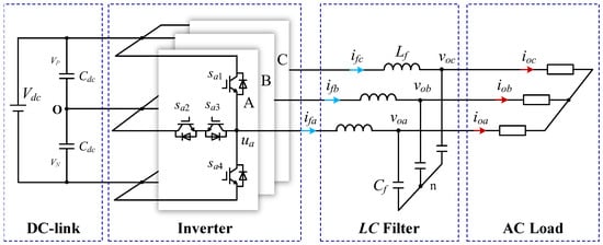
Figure 1.
System structure of three-phase VSIs in stand-alone operation.

Table 1.
System variables of stand-alone three-phase VSIs.
Based on Kirchhoff’s current and voltage laws applied to the LC filter, the AC-side voltage and current dynamics are described by the following equations: [24]:
where .
The dynamic equations established in the three-phase stationary reference frame, given by Equation (1), can be converted into the two-phase stationary reference frame using the following transformation:
where . Subsequently, in the frame, dynamics Equation (1) take the form
where .
Accordingly, the dynamic model can be further converted into the synchronous rotating reference frame from the two-phase stationary frame, where the corresponding transformation is defined as
where, is the translation angle, denotes the initial phase angle, represents the angular frequency, and f is the fundamental frequency.
In the two-phase synchronous rotating frame, Equation (4) is transformed to
where .
Based on the above equation, the dynamic model for three-phase VSIs in stand-alone operation is represented as follows:
where is the load disturbance, parameter uncertainty and cross-coupling effect inherent to the synchronous reference frame. It is noteworthy that and contain load disturbances and .
2.2. Important Assumption and Lemmas
Prior to the controller design, the fundamental assumption and mathematical lemmas utilized in this paper are presented below.
Assumption 1.
Given that the three-phase VSI system constitutes a physical system, it is hypothesized that both matched and unmatched disturbances, designated as and their derivative , are assumed to be bounded; there exists a positive constant and such that and , i=1,2,3,4 [25,26].
Remark 1.
For the three-phase VSI system, includes load disturbances, parameter uncertainties, and cross-coupling effects. Taking load disturbance as an example, it is an unknown disturbance related to capacitance parameters and load currents. Considering that the voltage and current states of the VSI system, as well as their rates of change, are subject to physical constraints, Assumption 1 is reasonable and widely accepted in relevant studies [27,28,29].
Lemma 1.
Consider the nonlinear system . Let be a continuous positive definite function. If there exist scalars , , and that satisfy the following conditions [13]:
then the origin of the system possesses practical finite-time stability, and for a scalar δ with , there exists a constant such that for all ,
and is defined by
where is the initial time.
Lemma 2.
Consider a second-order nonlinear system of the form [8]
where is a continuous and piecewise second-order differentiable input signal. and are the given constants. is a to-be-designed parameter. and are state variables of the aforementioned second-order nonlinear system. There exist constants and such that for ,
3. Controller Design
To achieve robust AC output voltage regulation for a three-phase VSI under time-varying load disturbances, this section introduces an FTBC method with an FTSMDO. The proposed method retains the traditional cascaded double-loop structure. To improve dynamic performance and robustness against disturbances, an FTSMDO is incorporated to achieve rapid and accurate estimation of matched and unmatched disturbances within the system. Furthermore, a finite-time differentiator is adopted to circumvent the problem of “explosion of complexity” associated with repeated differentiation in the standard backstepping procedure. Finally, a strict stability analysis is furnished for the closed-loop stand-alone three-phase VSI system.
3.1. Finite-Time Backstepping Controller
By combining the backstepping technique with Lyapunov functions that satisfy the Lemma 1, the desired continuous finite-time controller can be obtained. Figure 2 shows the control structure of the controller. The fundamental principle of backstepping control involves recursively decomposing a higher-order nonlinear system into a sequence of lower-order subsystems, for which virtual or actual control laws are systematically designed. This recursive process simplifies both the system representation and the control synthesis. The subsequent section details the step-by-step recursive design of the proposed finite-time backstepping controller.
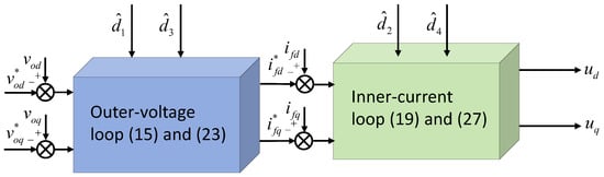
Figure 2.
Block diagram of continuous FTBC.
First, the tracking error is defined as
where the superscript “*” denotes the corresponding desired value and the control objective is to ensure that a converges to a small neighborhood around zero within finite time.
Step 1: Regarding the controller design, achieving accurate control for output voltage is the primary objective. It is noteworthy that the dynamic model of the stand-alone VSI under the two-phase synchronous rotating coordinate frame is a second-order system. Consequently, auxiliary state variables and virtual control laws are accordingly devised to guarantee the finite-time tracking of the output voltage. Based on the aforementioned analysis, selecting the first Lyapunov function as follows:
Substituting the tracking error of the voltage component on the d-axis into the derivative of yields
The design of the virtual control law should ensure that Equation (14) satisfies practical finite-time stability, thus obtaining
Substituting the virtual control law into Equation (14), we obtain
where and the superscript “~” refers to the error term in the interference estimation process, specifically . According to Equation (16), if converges to a small neighborhood of the origin within a finite time, then the virtual controller designed in this paper satisfies the practical finite-time stability condition given by Lemma 1, and thus achieves the predetermined control objective.
Step 2: In order to ensure that the tracking error of the d-axis subsystem can converge to a small neighborhood near zero in finite time, select the Lyapunov function as
Combining Equations (6) and (17), and substituting the tracking error of the current component on the d-axis into , we obtain
Combining Equations (15) and (18), and satisfying its negative definiteness and finite-time stability, the actual control law can be constructed as
Therefore, substituting the actual control law (Equation (19)) into derivative Equation (18), can be reconstruct as
Step 3: Similarly, to ensure that the q-axis subsystem can achieve finite-time stability, selecting the Lyapunov function is
Substituting the tracking error of the voltage component on the q-axis into the derivative of , we obtain
To satisfy the finite-time stability of Equation (22), the virtual control law is constructed as
According to the virtual control law, the derivative of can be rewritten as
Step 4: Finally, the Lyapunov function is selected as
Substituting the tracking error of the current component on the q-axis into the derivative of , we obtain
The design of the actual control law needs to ensure that can converge in finite time, and (26) should satisfy Lemma 1, so we can obtain
According to the actual control law , the derivative of can be rewritten as
where r is between 0 and 1. The and are adjustable parameters, . Estimation results of the system lumped disturbances are defined as . , , , represent the derivatives of the virtual control signals. The specific form of the above signals will be derived in a subsequent section.
3.2. Finite-Time Differentiator
Although numerical differentiation enables the acquisition of differential signals, it inevitably introduces random noise components, which can lead to system instability. Therefore, we introduce a finite-time differentiator to obtain the required differential signals.
According to Lemma 2, the differential signals required in the control law can be obtained through a finite-time differentiator within finite time. For the finite-time differentiator, its detailed structure is outlined below:
where the input signal is and the output signal is , and are adjustable parameters.
According to Lemma 2, the estimation errors satisfy
when , the estimation error of the required differential signal will converge to a small neighborhood around zero.
3.3. Fixed-Time Disturbance Observer
Based on the above analysis, the matched and mismatched disturbances included in the previously obtained dynamic model will reduce the system’s control performance. Therefore, it is necessary to construct an observer to effectively estimate the disturbances. This section constructs an FTSMDO to observe the lumped disturbances of the system [30], and its structure is described as follows:
where . The specific variables are expressed as
where , , i = 1, 2, 3, satisfy and where and for sufficiently small constants and . The observer gains (i = 1, 2, …, 6) should be designed ensuring the following matrices are Hurwitz:
Under Assumption 1, it has been established in Ref. [31] that the estimation error of the disturbance observer converges to a bounded set near the origin within a fixed time , i.e., . Notably, this convergence time is independent of the system’s initial conditions. The convergence rate of the observer plays a significant role in determining the overall control performance. The FTSMDO presented in this work enables accurate disturbance estimation and timely compensation within the controller, thereby enhancing the system’s robustness.
3.4. Stability Proof
It is crucial to select a suitable Lyapunov function in order to demonstrate the practical finite-time stability of the designed controller. In this section the final Lyapunov function is the same as (28), that is, .
Based on Young’s inequality, we obtain the following equation:
for . Substituting Equation (34) into Equation (33), we obtain
where , , .
By tuning the control parameters to make (35) satisfy Lemma 1 with and , the closed-loop system will be practically finite-time stable: its tracking error can converge within a finite time, and the system also exhibits excellent robustness. The radiuses of the region of the tracking error are
4. Simulation Results
In practice, to ensure the three-phase VSI system has good tracking performance and rapid dynamic response, we have successively designed the parameters of the finite-time controller, finite-time differentiator, and disturbance observer. Next, this paper will introduce the parameter tuning suggestions.
For the finite-time controller, according to Equations (35) and (36), large contribute to large ; subsequently, small tracking errors can be obtained.
For the finite-time differentiator, small leads to small estimation error and small , which contributes to small tracking errors. and are only used for increasing adjustment freedom for the finite-time differentiator [3].
For the disturbance observer, the tuning conditions for the observer parameters , , and are provided in Section 3.3, where , (), and () should be designed ensuring Equation (32) is Hurwitz.
The design procedure is given as follows:
- Select () from small to large. Adjust the inner loop parameters first, then adjust the outer loop, so and are chosen first. is usually chosen to be between one-half and one-third of ;
- Select from large to small at the pregiven and , then and are tiny tuned to further improve control performance.
- Select , and according to the tuning conditions in Section 3.3.
In the following experiments the finite-time controller parameters are configured as follows: , , , , , . In terms of the FTSMDO, the parameters are set as , , , , , , , and . The reference values are , . The parameters of the finite-time differentiator are selected as , and .
The PI control and CDO-BSC method in [11] are also implemented and compared with the proposed FTSMDO-FTBC method. Figure 3, Figure 4 and Figure 5 present the control performance test results of three control methods—traditional PI control, the CDO-BSC scheme [11] and the FTSMDO-FTBC scheme under different load conditions. The tested load conditions include linear RL loads, unbalanced loads, and load variations. Table 2 provides a performance comparison between the three control methods, where the root mean square error (RMSE) of the output voltage and total harmonic distortions (THDs) are used to evaluate steady-state performance, and overshoot and settling time are used to assess dynamic performance.
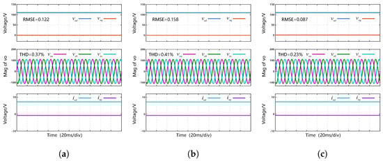
Figure 3.
Test results of control performance under linear RL loads: (a) PI control (b) CDO-BSC (c) FTSMDO-FTBC.
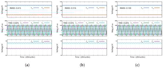
Figure 4.
Test results of control performance under unbalanced loads: (a) PI control (b) CDO-BSC (c) FTSMDO-FTBC.
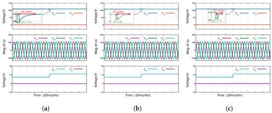
Figure 5.
Test results of control performance under loads variation: (a) PI control (b) CDO-BSC (c) FTSMDO-FTBC.
Table 2.
Comparison of different control methods.
Figure 3 shows the steady-state control performance of the three control methods under linear RL loads, including the dq axes output voltages, three-phase AC output voltage, and the dq axes output currents. A linear RL load is equivalent to introducing constant load disturbances. Under constant disturbances, three control methods achieve excellent steady-state control performance and provide three-phase symmetric AC output voltages, with small output voltage RMSE and low THD. The FTSMDO-FTBC scheme enables finite-time tracking control, resulting in better output voltage control performance.
Figure 4 shows the control performance of the three control methods under unbalanced loads. Under unbalanced loads, three control methods maintain low output voltage THD (PI: 0.44%; CDO-BSC: 0.35%; FTSMDO-FTBC: 0.26%). However, the PI control and CDO-BSC exhibit a large output voltage RMSE (PI: 0.415 V; CDO-BSC: 0.316 V) and significant fluctuations in the d-axis output voltage, which in turn leads to asymmetric AC output voltages. In contrast, the proposed FTSMDO-FTBC method still achieves superior output voltage tracking control performance under unbalanced loads, with an RMSE of only 0.100 V. The proposed FTSMDO-FTBC method reduces the RMSE by approximately 69% compared to the existing CDO-BSC and PI methods. For the THD, the FTSMDO-FTBC method is superior to the CDO-BSC method and the PI control.
Figure 5 shows the dynamic response performance of the three control methods under load variations. In the initial stage, the stand-alone voltage-source converter is connected to a linear RL load. Subsequently, the AC-side resistive load is changed from to to simulate load variation. After the load change, three control methods can restore the increased output voltage to the reference voltage, but there are significant differences in the setting time and overshoot of the output voltage. Specifically, the PI control requires 6.0 ms to restore the output voltage to the reference value, with an overshoot of 11.5 V, and the BSC requires 2.0 ms to restore the output voltage to the reference value, with an overshoot of 6.4 V. The proposed FTSMDO-FTBC method shortens the output voltage settling time to 1.0 ms and the voltage overshoot is 7.7 V. The overshoot of the proposed FTSMDO-FTBC method is similar to that of the CDO-BSC method, but the setting time is reduced by 50%.
5. Conclusions
This paper proposes an FTBC strategy for three-phase VSIs based on an FTSMDO. Leveraging the backstepping control concept, the system is decomposed into subsystems to recursively design control laws, ensuring the finite-time tracking. Meanwhile, the FTSMDO is utilized to quickly estimate system disturbances with convergence time independent of initial conditions, effectively compensating for the impact of disturbances on control performance. This strategy does not rely on load current sensors, reducing hardware costs and improving system reliability. It can effectively suppress disturbances under nonlinear and unbalanced loads, enhance AC voltage regulation accuracy and system robustness, and provide a feasible solution for the high-performance control of three-phase VSIs in stand-alone mode. Future work can further optimize the observer parameters or extend it to more complex systems to verify its applicability and focus on the innovation of control algorithms for inverter systems.
Author Contributions
Conceptualization, S.W. and C.F.; methodology, S.W. and C.F.; software, C.F., S.W. and D.P.; formal analysis, S.W., L.C. and D.P.; data curation, S.W. and D.P.; writing—original draft preparation, S.W.; writing—review and editing, S.W., C.F., L.C., G.Z. and X.W.; visualization, S.W., G.Z. and X.W.; supervision, C.F., G.Z., L.C. and X.W. All authors have read and agreed to the published version of the manuscript.
Funding
This research was funded by the National Natural Science Foundation of China under Grant 62503261 and the National Natural Science Foundation of China under Grant 62273205, and in part by Natural Science Foundation of Shandong Provincial under Grant ZR2025QC1565.
Data Availability Statement
The data that support the findings of this study are available from the corresponding author upon reasonable request.
Conflicts of Interest
The authors declare no conflicts of interest.
References
- Stephen, S.S.; Shareef, H.; Errouissi, R.; Eslami, M.; Hashfi, T.B. Disturbance Observer-Based Feedback Linearized Controller for Grid-Forming Four-Leg VSI Supplying Unbalanced and Nonlinear Loads. Energies 2024, 17, 3319. [Google Scholar] [CrossRef]
- Hu, X. Virtual Power Grid Flux-Oriented Vector Control for Three-Phase Voltage-Type PWM Rectifier. Int. J. High Speed Electron. Syst. 2025, 34, 2440009. [Google Scholar] [CrossRef]
- Fu, C.; Zhang, C.; Zhang, G.; Song, J.; Zhang, C.; Duan, B. Disturbance Observer-Based Finite-Time Control for Three-Phase AC–DC Converter. IEEE Trans. Ind. Electron. 2021, 69, 5637–5647. [Google Scholar] [CrossRef]
- Hannan, M.A.; Lipu, M.S.H.; Ker, P.J.; Begum, R.A.; Agelidis, V.G.; Blaabjerg, E. Power Electronics Contribution to Renewable Energy Conversion Addressing Emission Reduction: Applications, Issues, and Recommendations. Appl. Energy 2019, 251, 113404. [Google Scholar] [CrossRef]
- Özen, F.; Ortaç Kabaoğlu, R.; Mumcu, T.V. A Lightweight and Efficient Deep Learning Model for Detection of Sector and Region in Three-Level Inverters. Electronics 2025, 14, 3876. [Google Scholar] [CrossRef]
- Liu, P.; Wang, Z.; Xu, Y.; Zou, Z.; Deng, F.; Li, Y. Improved Harmonic Profile for High-Power PWM Current-Source Converters with Modified Space-Vector Modulation Schemes. IEEE Trans. Power Electron. 2021, 36, 11234–11244. [Google Scholar] [CrossRef]
- Chen, Q.; Tan, Z.; Xiang, B.; Qin, L.; Zhou, Z.; Gao, S. Active Neutral-Point Voltage Balancing Strategy for Single-Phase Three-Level Converters in On-Board V2G Chargers. Energies 2025, 7, 406. [Google Scholar] [CrossRef]
- Ding, H.; Wang, J.; Guo, X.; Li, S.; Guerrero, J.M. Fixed-Time Sliding-Mode Disturbance Observer-Based Finite-Time Backstepping Control for Current Source Rectifier. IEEE J. Emerg. Sel. Top. Power Electron. 2024, 12, 4767–4778. [Google Scholar] [CrossRef]
- Zhang, X.; Ma, Z.; Cai, X.; Wu, X.; Han, Y.; Lin, G. Enhanced Accuracy Finite-Control-Set Model-Predictive Control for Three-Phase Three-Level NPC Inverter. IEEE Trans. Power Electron. 2025, 40, 10330–10334. [Google Scholar] [CrossRef]
- Komurcugil, H.; Biricik, S.; Bayhan, S.; Zhang, Z. Sliding Mode Control Overview of Its Applications in Power Converters. IEEE Ind. Electron. Mag. 2020, 15, 40–49. [Google Scholar] [CrossRef]
- Huang, S.; Li, G.; Yu, H.; Wang, X.; Li, S.; Li, Q. Composite-Disturbance-Observer-Based Backstepping Control for Three-Phase Inverters with Multiple Disturbances. Control Eng. Pract. 2023, 138, 105599. [Google Scholar] [CrossRef]
- Fu, C.; Liu, J.; Zhang, Z.; Wang, Q.G.; Yu, J. Cascade Finite-Time Adaptive Control for Stand-Alone Inverters with Load Disturbances. IEEE Trans. Autom. Sci. Eng. 2025, 22, 16512–16521. [Google Scholar] [CrossRef]
- Yu, J.; Shi, P.; Zhao, L. Finite-time Command Filtered Backstepping Control for A Class of Nonlinear Systems. Automatica 2018, 92, 173–180. [Google Scholar] [CrossRef]
- Chen, L.; Li, C.; Sun, Y.; Ma, G. Distributed Finite-Time Tracking Control for Multiple Uncertain Euler–Lagrange Systems with Input Saturations and Error Constraints. IET Control Theory Appl. 2019, 13, 123–133. [Google Scholar] [CrossRef]
- Yu, X.; Feng, Y.; Man, Z. Terminal Sliding Mode Control–An Overview. IEEE Open J. Ind. Electron. Soc. 2020, 2, 36–52. [Google Scholar] [CrossRef]
- Liu, Z.; Sun, N.; Yang, T.; Liu, G.; Fang, Y. Assembly-Oriented Finite-Time Coordinated Control of Underactuated Dual Rotary Cranes for Payload Position and Attitude Regulation. IEEE Trans. Autom. Sci. Eng. 2023, 21, 3678–3690. [Google Scholar] [CrossRef]
- Li, R.; Feng, W.; Qie, T.; Liu, Y.; Fernando, T.; Iu, H.H.; Zhang, X. A Computationally Efficient Learning-Based Control of a Three-Phase AC/DC Converter for DC Microgrids. Energies 2025, 18, 2383. [Google Scholar] [CrossRef]
- Wen, G.; Zheng, W.X.; Du, H.; Feng, G. Homogeneous Constrained Finite-Time Controller for Double Integrator Systems: Analysis and Experiment. Automatica 2021, 134, 109894. [Google Scholar] [CrossRef]
- Niu, Z.; Zuo, Y.; Wang, H.; Zhang, L.; Zhu, X.; Lee, C.H. Improved Low-Frequency Disturbance Rejection Property for Position Control of PMSM Using Generalized Extended State Observer. IEEE J. Emerg. Sel. Top. Power Electron. 2023, 11, 4739–4748. [Google Scholar] [CrossRef]
- Li, Y.; Hu, Y.; Ma, X.; Liu, L. Sensorless Control of Dual Three-Phase IPMSM Based on Frequency Adaptive Linear Extended State Observer. IEEE Trans. Power Electron. 2023, 38, 14492–14503. [Google Scholar] [CrossRef]
- Heo, G.; Choi, S.; Park, Y. Disturbance-Observer-Based Virtual Impedance for Virtual Synchronous Generators. IEEE Trans. Ind. Appl. 2025, 61, 8595–8605. [Google Scholar] [CrossRef]
- Duong, A.T.; Pham, T.L.; Vu, P. Disturbance Observer Based on Fixed Time Sliding Mode Control and Optimal State Observer for Three-Phase Three-Level T-type Inverters. IEEE Access 2023, 11, 62091–62108. [Google Scholar] [CrossRef]
- Li, T.; Liu, X.; Yu, H. Backstepping Nonsingular Terminal Sliding Mode Control for PMSM with Finite-Time Disturbance Observer. IEEE Access 2021, 9, 135496–135507. [Google Scholar] [CrossRef]
- Do, T.D.; Leu, V.Q.; Choi, Y.S.; Choi, H.H.; Jung, J.W. An Adaptive Voltage Control Strategy of Three-Phase Inverter for Stand-Alone Distributed Generation Systems. IEEE Trans. Ind. Electron. 2012, 60, 5660–5672. [Google Scholar] [CrossRef]
- Wang, X.; Yang, J.; Liu, C.; Yan, Y.; Li, S. Safety-Critical Disturbance Rejection Control of Nonlinear Systems with Unmatched Disturbances. IEEE Trans. Autom. Control 2024, 70, 2722–2729. [Google Scholar] [CrossRef]
- Du, Y.; She, J.; Cao, W. Improving Performance of Disturbance Rejection for Nonlinear Systems Using Improved Equivalent-Input-Disturbance Approach. IEEE Trans. Ind. Inform. 2023, 20, 941–952. [Google Scholar] [CrossRef]
- Zhao, Z.; He, X.; Ahn, C.K. Boundary Disturbance Observer-Based Control of a Vibrating Single-Link Flexible Manipulator. IEEE Trans. Syst. Man Cybern. Syst. 2019, 51, 2382–2390. [Google Scholar] [CrossRef]
- Li, W.; Zhang, Z.; Wang, P.; Wan, H. A Faster Fixed-Time Fault Tolerant Sliding Mode Control for Robot Manipulators with Mismatched Disturbances. IEEE Access 2025, 13, 56576–56586. [Google Scholar] [CrossRef]
- Dai, C.; Guo, T.; Yang, J.; Li, S. A Disturbance Observer-Based Current-Constrained Controller for Speed Regulation of PMSM Systems Subject to Unmatched Disturbances. IEEE Trans. Ind. Electron. 2020, 68, 767–775. [Google Scholar] [CrossRef]
- Sarrafan, N.; Zarei, J.; Horiyat, N.; Razavi-Far, R.; Saif, M.; Mijatovic, N.; Dragičević, T. A Novel Fast Fixed-Time Backstepping Control of DC Microgrids Feeding Constant Power Loads. IEEE Trans. Ind. Electron. 2022, 70, 5917–5926. [Google Scholar] [CrossRef]
- Ni, J.; Liu, L.; Chen, M.; Liu, C. Fixed-Time Disturbance Observer Design for Brunovsky Systems. IEEE Trans. Circuits Syst. II Express Briefs 2017, 65, 341–345. [Google Scholar] [CrossRef]


Disclaimer/Publisher’s Note: The statements, opinions and data contained in all publications are solely those of the individual author(s) and contributor(s) and not of MDPI and/or the editor(s). MDPI and/or the editor(s) disclaim responsibility for any injury to people or property resulting from any ideas, methods, instructions or products referred to in the content. |
© 2026 by the authors. Licensee MDPI, Basel, Switzerland. This article is an open access article distributed under the terms and conditions of the Creative Commons Attribution (CC BY) license.