Abstract
Methane (CH4) is one of the most important greenhouse gases, and substantially impacts climate change. Over a 20-year period, its global warming potential (GWP) is approximately 80 times higher than that of carbon dioxide (CO2). One of the significant sources of methane emissions is the hard coal mining industry, particularly regarding the release of methane with mine ventilation air. Methane released from coal seams during mining operations and discharged into the atmosphere through exhaust shafts is referred to as VAM (Ventilation Air Methane). In the context of the European Union’s climate policy, activities aimed at reducing and utilizing VAM emissions are gaining increasing importance. One initiative supporting the development of such solutions is the research project ProVAM (Reduction of Ventilation Air Methane Emissions in the Coal Mining Transformation Process), implemented by a consortium of scientific and industrial institutions from EU member states. The project focuses on developing guidelines and selecting technologies dedicated to the utilization of VAM. This article presents a methodology for assessing parameters associated with VAM emissions and provides a characterization of the selected mine exhaust shafts analyzed within the ProVAM project. Key technical factors affecting the feasibility of using oxidation technologies to reduce methane emissions from hard coal mining are identified.
1. Introduction
Methane emission from hard coal mining is a key environmental and occupational safety challenge. Methane is a gas with a short atmospheric lifetime but a very high greenhouse gas potential, and global emissions from fossil fuel sources have remained above 120 Mt annually for years. The latest IEA reports highlight the growing share of disused shafts and workings in this process. Their share in methane emissions was estimated at 8 Mt in 2024 [1]. In mine environments, methane poses a direct explosion and fire hazard, which determines the arrangement and parameters of mine ventilation, as well as the operating regimes of shafts and main fan stations. Therefore, assessing ventilation shafts for VAM processing requires the consideration of many aspects: climate, energy, economics, and safety. The sources of methane emissions in mines are diverse and include the following:
- Diluted methane in a ventilation stream (VAM, typically 0.1–1% CH4);
- Methane drainage gas, i.e., methane captured by drainage from the rock mass (CMM/CBM; 30–95% CH4);
- Post-mining emissions from abandoned workings and closed shafts (AMM).
In hard coal mining, a significant share of methane emissions is associated with VAM (Ventilation Air Methane), i.e., methane present in the ventilation air expelled from underground workings. Although the CH4 concentration in this stream is usually low, the magnitude of emissions in mass terms is determined not only by concentration but also by the ventilation airflow rate in mines, which is very high. As a result, even a small methane content in a huge volume of air may mean that VAM accounts for the largest share of the total mass flow of CH4 emitted from a mine. At the same time, methane dilution constitutes a fundamental technological barrier to its processing and/or utilization, because the mixture has a low heating value and does not ensure stable combustion in conventional equipment. In practice, this means that despite the high importance of VAM in the methane emission balance, its management is more difficult than in the case of streams with higher CH4 concentrations, and technology selection must take into account both the low and variable methane concentration and the requirements of continuous, safe operation in the mining environment [2,3,4,5,6]. Classic studies and more recent technological reviews agree that commercial utilization of VAM requires either low-concentration oxidation technologies (thermal or catalytic) or the enrichment of VAM with high-methane streams (co-firing or assisted combustion of the CMM) [7,8].
In Poland, the methane content in coal seams and the emission structure are specific to given geological and mining conditions. Historical and contemporary analyses show that, despite technological progress, total mine emissions remain high, and the share of emissions from ventilation remains significant. Recent studies from 2023 to 2025 indicate that total emissions from Polish mines exceeded 750 million m3 in 2023, of which over 70% were released directly into the atmosphere from ventilation. At the same time, the importance of emissions from closed mines and abandoned shafts is growing, which requires their inclusion in planning for the reclamation and monitoring of post-mining areas [9,10]. Methane risk is directly related to occupational safety and determines the organization of ventilation in mining areas (longwalls and roadways), the selection of ventilation shaft operating parameters, and the mine’s output. Polish studies show that the methane hazard category, the dynamics of methane emissions in mining areas, and the effectiveness of preventive methods (including methane drainage) directly impact available shaft capacity reserves, fan stability, and even the need to reconstruct ventilation outlets and shaft towers [11,12]. Regulatory requirements are increasingly influencing technological and technical requirements. In 2024, the European Union adopted a regulation on reducing methane emissions in the energy sector, which introduces, among other things, monitoring, reporting, and emission limits, and, in the next few years, will also include requirements regarding the methane intensity of fuels introduced into the EU market. At the same time, the European Commission emphasizes that reducing methane emissions is essential to achieving climate goals by 2050. In Poland, occupational health and safety regulations are in force regarding methane hazard classification and ventilation requirements, as well as the use of methane drainage systems—which affects the design and operation of exhaust shafts as part of the ventilation system [13,14,15,16].
Forecasts regarding methane emissions indicate that there is significant, economically justified, potential for methane reduction in the mining industry. According to an IEA analyses, a significant portion of these emissions can be reduced using commercially available technologies, often at zero or low net cost, considering the energy value of the captured gas. This applies to both methane drainage projects and the use of CMM/AMM, as well as the utilization of VAM in oxidation and heat recovery plants. International case studies and project reviews show that integrating mine methane drainage systems with local energy generation and heating systems can deliver sustainable economic benefits while simultaneously reducing the plant’s methane emissions [1,17]. Considerable progress has been made in recent years regarding the utilization of drained mine methane. The Polish mining industry, for example, demonstrates numerous installations utilizing this gas for the production of heat, electricity, and cooling. In modern installations, this is achieved through trigeneration. Methane from aboveground methane drainage stations powers CHP generators, simultaneously producing electricity and heat for local networks. Surpluses can be used to produce coolness by powering sorption pumps [18,19].
The costs of methane emissions for the mining industry are both direct and indirect. Direct costs include future administrative penalties and environmental fees related to exceeding methane intensity thresholds and obligations regarding monitoring and reporting. Analyses for Poland show that the financial exposure of mines to EU methane regulations can be significant, especially for the entities with high relative methane production. Indirect costs include capital and operating expenses for methane drainage systems (holes, collectors, compressors, flares/incinerators, and generators), as well as the potential costs of lost production during downtime resulting from exceeded methane concentrations in mine workings. At the same time, feasibility studies and project experience from international markets indicate that CMM/AMM projects often achieve positive financial flows, especially when energy is consumed on-site or sold through support systems. Implementing VAM processing—although technically more difficult—can improve the emission balance of the plant, which becomes an additional “value” in the regulatory regime [17,20,21,22].
Key parameters for assessing ventilation shafts for VAM processing capabilities include the following:
- Characteristics of exhaust airflow (flow, diurnal-seasonal variability, CH4 concentration distribution, humidity, and temperature);
- Shaft configuration and technical condition (tower/chimney, ducts, silencers, and bypasses);
- Safety constraints (fire regulations, backflow risks, and impacts on the intensity of excavation ventilation);
- Integration with existing CMM drainage and energy management systems;
- Regulatory requirements (compliance with health and safety, environmental, and EU regulations).
These issues, among others, are addressed within the ProVam project [23].
2. Methods for and Technical Problems with the Processing of Ventilation Methane
Selecting a technology for processing methane from mine ventilation air is especially challenging. VAM is not just a mixture of air and methane. It contains dust, a large amount of water, and may contain gaseous contaminants such as H2S or SO2.
The technology used should be tailored to the specific shaft. Awareness of the scale of emissions from ventilation shafts and knowledge of VAM parameters over time are essential for the effective development of the suggested VAM processing technology. A review of available VAM technologies, their advantages and disadvantages, and application limitations can be found in [22].
Due to the very low methane concentration in the ventilation air stream (the maximum permissible in the exhaust shaft is 0.75%), and the enormous volumes of gas flowing (even exceeding 300,000 m3/h), its processing requires the use of technologies that enable stable methane oxidation under highly diluted conditions. In recent years, regenerative thermal oxidation (RTO/TFRR) and regenerative catalytic oxidation (RCO/CFRR) technologies have attracted the greatest interest, providing high conversion efficiency and the possibility of thermal energy recovery [22,24,25,26,27,28,29,30,31].
RTO (Regenerative Thermal Oxidizer) technology, or its variant, TFRR (Thermal Flow Reversal Reactor), utilizes ceramic beds with high heat capacity through which a mixture of air and methane flows. The CH4 oxidation at temperatures of approximately 900–1000 °C produces CO2 and H2O, and the bed accumulates the reaction heat. Periodic reversals of flow direction allow for a self-sustaining process without the use of auxiliary fuel. Methane conversion rates of up to 95–98% can be achieved, and the recovered heat can be used to produce steam, cool air, heat air, or power ORC (Organic Rankine Cycle) economically justified cycles. Disadvantages include the risk of local overheating and NOx emissions at excessively high temperatures, as well as a relatively large pressure drop in the ventilation duct [25,26,27,28,29,30]. It should be mentioned that, according to data for 2024, RTO technology was the only technically and commercially proven technology for effective VAM oxidation. It was confirmed that such installations can operate stably at methane concentrations of 0.2%, and VAM recovery is possible from methane concentrations above 0.5%. Furthermore, they are resistant to typical fluctuations in methane concentration resulting from mine operation [22].
RCO (Regenerative Catalytic Oxidizer) technology, or its variant, CFRR (Catalytic Flow Reversal Reactor), is a modification of RTO by using catalysts that lower the methane ignition temperature to 600–750 °C. The most commonly used catalysts are Pd/Pt supported on ceramic monoliths (e.g., cordierite), which increase reaction activity and reduce CO and NOx emissions. Currently, intensive research work is underway on oxide catalysts (MnOx–CeO2 and Co3O4–ZrO2) with similar activity and lower production costs [28,30]. CFRR reactors enable heat recovery similar to RTO, but at a lower temperature and reduced risk of overheating, making them more suitable for the mine environment. Currently, several installations are undergoing pilot testing or laboratory-scale demonstrations, but so far without success [22]. To increase the thermal stability of RTO/RCO reactors, blending VAM with richer mine gas (CMM—Coal Mine Methane) is often used. This solution allows for the reaction temperature to be maintained even at very low CH4 concentrations. The VAMMIT™ system developed by CSIRO (Canberra, Australia), in which heat from the VAM oxidation process drives a microturbine or ORC cycle, enabling partial conversion of the heat into electricity, is an example of a practical implementation.
For mines with very low CH4 concentrations, methane adsorption–desorption technology on porous materials (zeolites or activated carbon) is being developed, which enables periodic “concentration” of methane to 2–5% by volume [27]. This concentrated gas can then be burned in a gas engine or catalytic reactor. Although this solution is still at the testing stage, it could be an alternative for mines with variable flow rate value.
Another potential technological solution suggests the auxiliary use of VAM, for example, in power generation equipment where high temperatures are achieved by burning another fuel. Unfortunately, in most cases, ventilation shafts are located a considerable distance from the power plant, meaning that transporting such large volumes of accompanying gases with a small amount of methane is not economically justified. VAM can also be used as a primary stream in some technologies, such as catalytic, thermal, and adsorption technologies.
Considering the methane concentration in VAM, the volume and variability of the streams, and the efficiency of known technologies, thermal or catalytic oxidation appears to be the most promising processing method. In both methods, methane is combusted into CO2 and H2O in a fixed-bed reactor. In the catalytic process, the reactor packing is catalytically active, unlike in the thermal process.
Dust, moisture, and possible sulfur compounds are believed to have the greatest negative impact on the success of the VAM process. According to literature, the minimum methane concentration for oxidation in reverse-flow reactors is 0.2% by volume [31,32], 0.3% by volume for a thermal reactor [28,33], and 0.1% by volume [3] or 0.13% by volume [34] for a catalytic reactor. Higher methane concentrations improve the operation of a thermal reactor. An increase in methane concentration causes an increase in temperature inside the reactor, allowing for the utilization of excess energy. However, in the case of catalytic reactors, even a short-term increase in methane concentration, and thus an increase in temperature within the reactor, can lead to catalyst destruction [35]. Another serious challenge is dust. Its amount varies throughout the day and depends on the type of mining operation [25]. It should be noted that this contamination poses significant technical challenges for all known and developing technologies. It is important to note that dust contains both flammable and non-flammable components [36]. The first of these is coal, which will be burned in a high-temperature process. A high proportion of this fraction in dust can cause the formation of so-called hot spots during combustion, which are particularly hazardous to catalysts. It is known that hard coal deposits can contain sulfur compounds. Therefore, dust generated during coal mining will also contain them. These compounds can reduce catalyst activity and cause corrosion of equipment or monitoring devices. Tests of the effect of SO2 on a palladium catalyst were conducted in [37]. The results showed rapid deactivation of the catalyst. Rock dust is another dust fraction, the presence of which in a mine is important to protect against coal dust explosions. If rock dust also contains salt, it can cause the sintering of dust particles at high temperatures in the device. Silica or calcium compounds can also have a destructive effect on reactor beds and must be taken into account in installation design [22]. Considering the problems resulting from the presence of dust in the VAM stream, determining its amount is crucial for the selection of the reactor bed. A well-selected filling ensures free dust flow and thus does not increase hydraulic resistance. As indicated by [38], the daily dust load can reach 232 kg. Subsequent three-month tests of composition of the ventilation air emitted to the atmosphere, in four gas-fired Australian mines, showed that the dust load can vary within the range of 0.13 to 4.47 mg/m3 [25]. However, tests in one of the shafts of the “Knurów-Szczygłowice” mine did not reveal any changes in the hydraulic resistance of the ventilation air stream through a monolithic bed [39]. The test device with two types of monolith (with channel widths of 3 × 3 mm and 5 × 5 mm) operated continuously from winter to summer (6 months), under significantly different ambient temperature and humidity conditions. In the tests presented in [28], the authors also note that the reactor bed, which allows for the free flow of dust, is resistant to its deposition. Another contaminant of particular importance for catalytic VAM processing methods is the steam content in the VAM. If the VAM stream temperature (at a humidity close to 100%) drops below the dew point, condensation will occur. Furthermore, water in contact with the catalytic bed will cover the active sites, inhibiting the oxidation process. This effect was observed in [40,41,42,43]. Attempts to reactivate the catalyst after contact with water showed that the deactivation was more or less reversible [44] depending on the catalyst type. Cu as a catalyst has a greater water resistance than Pd and Pt catalysts. Numerous water sorption and desorption tests showed that the catalyst activity did not return to the initial level after regeneration.
3. Elements of Assessing Hard Coal Mine Ventilation Shafts in Terms of Ventilation Methane Processing
Currently, about 97% of total hard coal production in the EU takes place in Poland, within the Upper Silesian Coal Basin (USCB). Methane is present in mines exploiting seams in the central and southern parts of the USCB. Furthermore, there is a correlation between mining depth and methane emissions. Mining seams located at great depths are associated with higher methane emissions. Methane is unevenly distributed in the deposit, making it impossible to precisely predict its content by on reconnaissance. The exact amount of methane released can only be determined when it is released from the rocks. It is continuously monitored in the airflow using automatic methane measuring systems.
Methane is generally removed from mining pits through ventilation. In the case of a significant methane hazard, it is also removed through methane drainage, i.e., the extraction of methane directly from the rock mass. The amount of methane released from a mine, known as the total methane content, is the sum of all methane released into mine workings, taking into account the amount of methane released into the atmosphere with ventilation air (VAM) and other sources, such as rock mass methane drainage (CMM). Total methane content is reported as an absolute value in m3/minute and as a relative value per ton of coal production (relative methane content).
In 2023, as part of the ProVAM project, 38 ventilation shafts emitting ventilation methane were identified in the USCB. Based on the results of this work, criteria were developed for assessing shafts for the use of VAM processing technology. The developed criteria, which cover technical issues, specify the following components:
- Average VAM emission rate and its variability;
- Average VAM concentration and its variability;
- Projected methane emission factor EF;
- Dust content in ventilation air;
- Sulfur content in ventilation air;
- Ventilation air humidity;
- Air flow rate;
- Type of main mine ventilation fan;
- Drive and control of the main mine ventilation fan;
- Main fan installation layout;
- Availability of space for the VAM processing installation;
- Availability of utilities required for the operation of the VAM processing installation;
- Noise emission restrictions.
3.1. Average VAM Emission and Its Changeability
The volume of VAM emissions from a ventilation shaft, alongside its concentration, is the most important technical factor for assessing the utilization of VAM processing installations. VAM emissions from a ventilation shaft vary over time. Their variability is directly related to mining operations and depends primarily on the methane content of the currently mined coal face in a given coal seam and the amount of methane captured to the methane drainage network. Furthermore, a whole range of potentially difficult-to-predict factors influences methane release into mine workings. Methane emission variability can be considered on an instantaneous and average basis, e.g., daily, monthly, or yearly.
Average annual VAM emissions is the parameter that best describes the scale of the negative impact of air exhaled from a ventilation shaft to the environment. In conjunction with mining plans, the average annual VAM emissions forecast for subsequent years vary from year to year. Methane content forecasts developed by mines takes into account a number of additional factors, such as the volume of gas-bearing layers, their gas content, the degree of drainage, permeability, the intake location relative to the coalfield, the goaf structure, and the distribution of aerodynamic potential in the area.
Ventilation shafts with the highest projected average annual VAM emissions are predestined for equipping with methane processing installations. Therefore, this criterion should be dominant, and the remaining evaluation criteria should be analyzed for them.
Figure 1 presents the VAM flow rates in each ventilation shaft, based on the example of mines belonging to PGG S.A. (the names of the mines and their shafts are coded under consecutive numbers). The highest average methane flow rate was recorded in shaft II of mine No. 8, reaching a maximum of 50.2 m3/min. The highest methane flow rate was recorded in shaft no. 1 of mine no. 4, at 63.6 m3/min. Table 1 presents the results of projected methane emissions for the same shafts during the expected mine operation period (until closure). The downward trend in methane emissions, which can be observed in the forecasts, is primarily related to the anticipated mine closure and the planned increase in methane utilization.
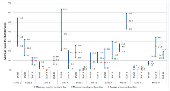
Figure 1.
Methane fluxes in ventilation shafts at PGG—2023.

Table 1.
Projected methane flows in ventilation shafts in PGG—from 2024 to 2049 [m3/min].
For the criterion “Average forecast VAM emission volume”, an assessment scale was proposed, as in Table 2. The VAM emission volumes were divided into seven ranges, which were assigned points from “0”, for the lowest average emission ≤ 10 m3/min, to “6” for the highest average emission above 60 m3/min, reflecting the scale of the impact of CH4 emissions on the environment.
Table 2.
Assessment criteria “Average forecasted VAM emission volume”.
3.2. Average VAM Concentration and Its Changeability
Volumetric concentration of VAM in the air exhaled from a ventilation shaft is, along with the VAM emission rate, the most important technical factor for assessing the VAM utilization installation. Methane concentration is a key parameter affecting the operation of an oxidation reactor. The following four threshold concentrations are defined for each reactor:
- Minimum, below which the reactor operation is completely uneconomical;
- Autothermal, above which the reactor operates autonomously without the need for additional external energy;
- Usable, above which excess energy can be utilized;
- Maximum, above which reactor can be damaged.
It is most advantageous to locate the VAM treatment plant near a shaft with methane emissions at the usable concentration. Secondly, locations with a concentration that ensures autothermal operation can be considered.
Methane flowrates and methane concentrations vary over time. Often, the instantaneous concentrations recorded between shifts and on non-working days are 0%. Cases where the momentary methane concentration drops below the minimum limit cause difficulties in terms of operating the methane processing plant. In such cases, the reactor operations may even be interrupted, requiring an external energy supply to restart.
Polish mining regulations stipulate that the maximum permissible methane concentration at the air inlet to the longwall is 1.0%, at the outlet from the longwall it is 2.0%, at the outlet from the ventilation area it is 1.5%, and in the exhaust shaft it is 0.75%. Mine ventilation services select the ventilation airflow to ensure that the permissible concentrations are not exceeded at any point. As a result, actual methane concentrations in the exhaust shaft do not exceed 0.7% by volume. Possible momentary exceedances may occur in the case of an unpredictable, sudden methane outburst or other failure, and are associated with the evacuation of personnel from the mine’s underground sections. Figure 2 shows the ventilation methane (VAM) concentration values in each exhaust shaft in the selected mines in Poland, indicating the highest and lowest methane concentrations, based on average monthly measurements from 2023. The average annual value of these measurements is also given. The highest methane concentration was recorded in shaft I of mine No. 4, at 0.49%. The highest average value, 0.33%, was recorded in shaft III of mine No. 10.
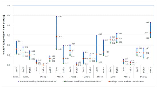
Figure 2.
Concentration of methane in exhaust shafts at PGG—2023.
The scoring for ventilation shafts depending on the predicted average VAM concentration is specified in Table 3. The predicted VAM concentrations were divided into seven ranges, each assigned a score from “0” for the lowest concentrations ≤ 0.1%, at which the operation of the oxidation reactor is economically unjustified, to “6” for the highest concentrations above 0.6%, at which the reactor’s operating efficiency is the highest.
Table 3.
The scores for the criterion of average predicted VAM concentration.
3.3. Forecast Methane Emission Factor (EF)
The methane emission factor is the ratio of the average CH4 emission amount to the emission source activity (amount of extracted coal). It is defined by the following formula:
where EF is the CH4 emission factor [kg/t], E is the amount of CH4 emitted into the air [kg], and AD is the emission source activity (amount of extracted coal) [t].
The methane emission factor can be used to assess the possibility of installing VAM processing. Regulation (EU) 2024/1787 [15] introduces emission limits based on extracted coal. From 1 January 2027, the release of methane into the atmosphere from exhaust shafts in coal mines emitting more than five tons of methane per kiloton of coal mined will be prohibited, and from 1 January 2031, the release of methane into the atmosphere from ventilation shafts in coal mines emitting more than three tones of methane per kiloton of coal mined will be prohibited. The provisions of the Methane Regulation stipulate that fines will be set at a level that effectively deprives organizations responsible for emissions of financial benefits resulting from violations. Mines that exceed the permissible emission limit should be especially interested in implementing VAM treatment facilities at the shafts with the highest methane emissions.
Scoring for ventilation shafts, depending on the forecast methane emissions, is specified in Table 4. The forecast methane emission factors are divided into seven ranges, each assigned a score ranging from “−6” for the lowest emission factor values ≤ 5 t CH4/1000 t of mined coal that are, in accordance with European Commission regulations, exempt from emission fees, to “6” for the highest emission factor, in locations where the use of VAM treatment facilities is most needed. The values presented in Table 4 are not the result of predictions in the sense of a mathematical model. They are established weights assigned to criteria based on an expert process conducted as part of the ProVAM project. The scores were developed through discussions and workshops within the project team.
Table 4.
The score for the criterion of forecast methane emission factor EF.
3.4. Dust in Ventilation Air
One of the most important technical factors limiting the use of VAM processing plants is ventilation air dust. Every oxidation reactor has a limited dust intake capacity in the process air. These limitations apply, to varying degrees, to both flammable and non-flammable dust.
Two parameters related to ventilation air dust should be considered for the assessment:
- Flammable dust content [mg/Nm3];
- Non-flammable dust content [mg/Nm3].
In each exhaust shaft considered for the location of a VAM processing plant, ventilation air dust content, including both flammable and non-flammable fractions, should be tested to ensure that the permissible values are not exceeded.
If even one value is exceeded, the methane oxidation plant must be equipped with an additional air filtration system. Given the large ventilation airflow, the filtering device must be of sufficient capacity, which requires additional space for installation. Furthermore, such devices introduce additional resistance into the installation, which must be neutralized by increasing the power of the fans used throughout the VAM processing plant. This will result in increased investment, operating, and maintenance costs. Another proposal is to design solutions that reduce the velocity of dust particles, allowing them to settle at the lowest points of the duct system or in collection pockets, from where they can be regularly removed [17].
The scoring for ventilation shafts depending on the dust content of the ventilation air is specified in Table 5. The scoring depends on meeting two conditions specified by the oxidation reactor manufacturer: the permissible combustible dust content Cp dop and the permissible non-combustible dust content Cn dop. For example, the requirements for the DÜRR Oxi X RV reactor were used:
- Cp dop < 10 [mg/Nm3];
- Cn dop < 1 [mg/Nm3].
For the assessment, the above conditions should be replaced with the appropriate values. If both conditions are met, a score of 3 is awarded. If at least one condition is not met, the score is negative because additional filtration equipment is required. The score reflects the complexity and energy consumption of the necessary filtration equipment.
Table 5.
The score for the criterion of dust concentration in ventilation air.
Table 5.
The score for the criterion of dust concentration in ventilation air.
| Dust Content in Ventilation Air | |
|---|---|
| perm. content of combustible and non-combustible dust not exceeded: Cp ≤ Cp dop and Cn ≤ Cn dop | 3 |
| perm. content of combustible dust exceeded and non-combustible dust not exceeded: Cp ≤ Cp dop and Cn ≤ Cn dop | −1 |
| perm. content of combustible dust not exceeded and non-combustible dust exceeded: Cp ≤ Cp dop and Cn ≤ Cn dop | −2 |
| perm. content of combustible and non-combustible dust exceeded: Cp ≤ Cp dop and Cn ≤ Cn dop | −3 |
3.5. Content of Sulfur in Ventilation Air
A technical factor that should be considered when assessing the use of a VAM processing plant is the sulfur content in the ventilation air. Under the conditions of using an oxidation reactor, the sulfur content parameter (expressed in mg/m3) specified by the technology manufacturer must not be exceeded.
If the sulfur content in ventilation air exceeds the permissible limit, a different reactor should be selected or an additional desulfurization system should be installed. If the above solutions cannot be implemented, the VAM processing plant should not be used in this location.
The scoring for ventilation shafts based on the sulfur content in ventilation air is specified in Table 6. The scoring depends on meeting the requirement specified by the oxidation reactor manufacturer—the permissible combustible dust content (Sdop). The requirements for the DÜRR Oxi X RV reactor were used as an example: Sdop < 10 [mg/Nm3]. The appropriate value for this requirement should be used for assessment. If the condition is met, 3 points are awarded. If the condition is not met, the score is negative because an additional desulfurization installation is required.
Table 6.
Scores for the criterion of sulfur content in ventilation air.
3.6. Humidity of Ventilation Air
Ventilation air humidity is another technical factor that may limit the use of VAM processing plants. If a given type of oxidation reactor has limitations in this regard, the assessment should include two further interrelated parameters measured at the diffuser outlet:
- Relative humidity;
- Ventilation air temperature.
In most cases, the condition for proper reactor operation is the lack of condensation in the inlet air. If the air at the diffuser outlet meets this requirement, it is sufficient to ensure that there is no temperature drop in the transfer ventube, which could lead to water vapor condensation.
If the condition of condensation-free operation is not met, the system must be equipped with an air dryer. The consequences of introducing a dryer are identical to those of a filter device: larger installation space required, increased flow resistance, and reduced economic efficiency. The points for ventilation shafts depending on the ventilation air humidity are defined in Table 7. Relative humidity was divided into seven ranges. The humidity range of 70% ≤ RH < 80%, the highest without any preventive measures against condensation, had assigned a value of “0.” Positive values were assigned to a low relative humidity of ventilation air. Negative values reflect the complexity of additional measures to prevent humidity condensation in the air reaching the reactor. The worst case of air saturated with water vapor was assigned a value of “−3.”
Table 7.
The scores for the criterion of humidity of ventilation air.
3.7. Air Flowrate
Airflow rate (expressed in m3/min) is a technical factor important for assessing the possibility of a VAM processing installation. It determines the scale of the investment. It affects size of the installation, the space required for its installation, power, the amount of energy required for its operation as well as the investment, operating, and maintenance costs.
Scoring for exhaust shafts based on the airflow rate is defined in Table 8. The flow rates presented in Table 8 are not the results of measurements taken at exhaust shafts. They are assumed to be multiples of the reference value of 2000 m3/min. Airflow rate is a parameter limiting the possibility of VAM processing installations. Therefore, a negative score was applied to the airflow rates in exhaust shafts in Poland. The limiting values were assumed to be multiples of the capacity of the DÜRR Oxi X RV dual-reactor module, which is 125,000 m3/h, or slightly over 2000 m3/min. Level “0” was assumed for the lowest range observed in Poland. Positive values were assigned to lower air flow rates, such as those found in Romania.
Table 8.
The score for the airflow criterion.
3.8. Type of Main Fan for the Mine Ventilation System
The type of main mine ventilation fan can serve as an additional technical factor in assessing the possibility of VAM processing installations. Knowledge of this type of fan determines the nominal airflow rate to be extracted from the diffuser and allows for the selection of the appropriate connection type for this intake or for its unification.
For example, single-flow centrifugal fans of the WPK series have diffusers integrated with the body of a rectangular outlet facing upward, the dimensions of which are proportional to the fan size.
For some axial fans, circular diffusers with an upward outlet have been designed.
At 37 Main Fan Stations (MFSs) operating at 38 exhaust shafts emitting VAM, 10 different types of main mine ventilation fans were identified in operation in 2023. In 2023 86 main mine ventilation fans were installed at exhaust shafts with VAM emissions.
The most commonly used type of main mine ventilation fan is the single-flow radial WPK mine fan, manufactured in three sizes since the 1970s by POWEN (later STALKON). In total 58 WPK fans were used, representing two-thirds (66%) of all analyzed fans.
The scoring of ventilation shafts based on the type of installed mine fan for main ventilation is specified in Table 9. This scoring system distinguishes two groups of main mine ventilation fan types, depending on the possibility of standardizing the connection of the VAM collection system to the diffuser. The most commonly used types, with a rectangular outlet diffuser directed upward, received a score of “1”, while the remaining ones received a score of “0.”
Table 9.
The scores for the criterion of the type of mine fan for the main ventilation shaft.
3.9. Drive and Control for the Main Fan of the Mine Ventilation System
The drive and associated control of the main mine ventilation fan is an additional technical factor in assessing the possibility of VAM processing installations.
The most commonly used single-speed synchronous motors operate at a constant speed, and the flow control is achieved by throttling the flow with flaps or changing the position of the guide vanes. According to fan characteristics, reducing fan output by increasing flow resistance reduces efficiency. Due to the standard requirement that the fan operate at an efficiency of no less than 0.8 times the maximum efficiency, the range of control using this method is significantly limited.
Reducing efficiency while maintaining practically constant efficiency can be achieved by reducing the fan speed. Changing the speed is achieved by adjusting the supply voltage parameters (frequency and amplitude) or changing the number of magnetic field poles. Two-speed synchronous motors extend the range of fan efficiency control compared to single-speed motors. Asynchronous motors with a frequency converter offer the widest range of fan efficiency control, enabling wide-ranging speed control. Knowing the fan control type allows us to estimate the range of exhaust airflow regulation and select the appropriate size for the methane collection system. For example, this system can be sized for the minimum feasible flow rate. The scoring of exhaust shafts based on the type of mine fan installed at the main ventilation shaft is specified in Table 10. This scoring system distinguishes two groups of fan types for main mine ventilation, depending on the possibility of unifying the connection between the VAM exhaust system and the diffuser. The most commonly used types, with a rectangular outlet diffuser directed upward, received a score of “1”, while the remaining ones received a score of “0”.
Table 10.
Criterion score for mine fan drive and control.
3.10. Arrangement of Main Fan Installation
The main fan installation arrangement is a technical factor that must be considered, as it dictates the size of the VAM processing installation’s connection to the fan diffusers.
In mines with VAM emissions, two-fan and three-fan main fan stations are used. The number of diffusers used to expel air corresponds to the number of fans, with the exception being cases where two axial fans share the same diffuser. The fans can be installed in a parallel, perpendicular, diagonal, or irregular arrangement.
The most advantageous solution is to connect the VAM installation to a single diffuser. It is relatively easy to connect two diffusers of fans installed in a parallel or perpendicular arrangement when they are located close together. A more extensive connection should be made for two fans installed in a diagonal arrangement. The most complex VAM processing installation connection systems are required for two-fan stations with irregular configurations, where the diffusers are located in different directions from the shaft and at large distances from each other, as well as for three-fan stations. Typical main fan installation arrangements in a two-fan station are shown in Figure 3.
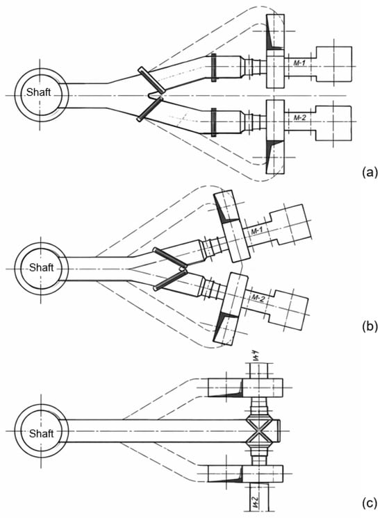
Figure 3.
Typical main fan installation arrangements in a two-fan station: (a) parallel arrangement, (b) diagonal arrangement, and (c) perpendicular arrangement [7].
Scoring for ventilation shafts based on the main fan arrangement is given in Table 11. Points were ranked based on the complexity and extent of the connection between the VAM processing installation and the main fan stations. A score of “0” was assigned to the typical, most compact cases of two-fan stations in parallel and perpendicular arrangements. The case of a two-fan station with a single diffuser received a score of “1”. Negative scores were assigned to the cases requiring more extensive connection than the base case. The two-fan station in a diagonal arrangement received a score of “−1”. A score of “−2” was assigned to the two-fan station in an irregular arrangement and to three-fan stations in linear and perpendicular arrangements. The most extensive connection case for a three-fan station in a diagonal arrangement received a score of “−3”.
Table 11.
Criterion score for main fan installation layout.
3.11. Availability of Space for the Development of a VAM Processing Plant
The parameter considered for space availability adjacent to the main fan station for development of a VAM processing plant depends on the assumed plant output and includes the area under the required number of reactor modules and associated equipment, such as dampers, fans, filters, dryers, etc., while also maintaining adequate access to them.
The site for the development of the plant should preferably be flat. For the selected locations, it should be verified whether the area considered for the development of a VAM processing plant is within the area of the shaft protective pillar. Figure 4 below shows the dimensions of a complete VAM Cube RE module in a sample VAM utilization plant.
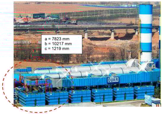
Figure 4.
Dimensions of Oxi X RE VAM installation [45].
The scoring for ventilation shafts based on space availability for the VAM processing installation is defined in Table 12. Shaft locations with an available flat surface received a score of “2”. The case with an available sloped surface received a score of “0”. The shaft rating was reduced to “−5” points when there was no available space on the plot and within the protective pillar.
Table 12.
The scores for the criterion of availability of space for VAM facilities.
3.12. Availability of Utilities Required for Operation of the VAM Processing Installation
Technical factors considered when assessing the use of a VAM processing plant for selected locations include the availability of utilities with the required following parameters:
- Main power supply:
- -
- Voltage;
- -
- Current;
- -
- Frequency.
- Auxiliary power supply with fuses:
- -
- Voltage;
- -
- Frequency.
- Compressed air:
- -
- Connection dimensions;
- -
- Pressure;
- -
- Humidity;
- -
- Cleanliness class;
- -
- Normal consumption;
- -
- Peak consumption.
Availability of these utilities is closely linked with the requirements of the planned VAM processing technology. Example requirements for utility parameters for DÜRR reactors are given in Table 13.
Table 13.
Requirements for utility parameters of Oxi.X RV VAM and Oxi.X RE VAM modules.
The scoring for ventilation shafts depending on the availability of utilities necessary for the operation of the VAM processing installation is defined in Table 14. Cases that do not require significant additional investment to ensure the availability of the required utilities received positive scores: “2” points when all utilities are available; “1” point when only auxiliary power is missing. A neutral score was assigned to cases in which the main power source is available and in which an auxiliary power source is also available. The remaining cases, requiring the provision of a main power source, received negative scores: “−1” point for two cases in which only compressed air of the required purity class is available, and “−2” points for cases in which it is not.
Table 14.
The scores for the criterion of availability of utilities required for the operation of the VAM utilization plant.
3.13. Noise Emission Restrictions
A characteristic parameter for this criterion is the distance of the noise source generated by the VAM processing installation from residential and industrial buildings. When assessing a potential location, it is important to verify whether permissible noise emission values will not be exceeded in each area. If such a risk exists, the installation should be soundproofed.
The scoring for ventilation shafts, depending on the applicable noise emission limits, is specified in Table 15. Noise emission restrictions, as always, received a negative score, with “0” indicating no such restrictions. The greatest noise emission reduction applies to single-family housing areas, whose vicinity was marked with a value of “−2”. The vicinity of multi-family housing areas was marked with a value of “−1”.
Table 15.
The scores for the criterion of restrictions related to noise emissions.
4. Conclusions
VAM currently represents one of the key environmental challenges in hard coal mining. Despite its low volumetric concentration, the very high ventilation airflow causes total CH4 emissions to reach significant levels. At PGG S.A. plants alone, they exceeded 188 million m3 in 2023. The high greenhouse potential of methane makes reducing its emissions, even at low concentrations, essential to achieving European climate goals.
As part of the project, a comprehensive inventory of exhaust shafts in the Upper Silesian Coal Basin (USCB), which are the main sources of VAM emissions, was undertaken. Thirty-eight ventilation shafts located within 37 main fan stations were identified, emitting methane through diffusers of various types and designs. Classification allowed us to distinguish several characteristic types of ventilation stations, differing in diffuser arrangement, air discharge direction, outlet shape, and height above ground level. The most advantageous solution for extracting the VAM stream proved to be a system of two adjacent rectangular diffusers open upwards, which allows for a compact connection to the collector and ensures stable flow conditions. Connecting a VAN disposal system to a three rectangular diffusers open upwards, arranged in a fan-like manner, is significantly more technically challenging. Capturing a specific portion of the ventilation airflow from a cylindrical diffuser open upwards, where the airflow spirals left or right depending on the fan in operation, can be problematic.
Spatial analysis indicated that peripheral shafts located on large industrial plots offer the greatest potential for building processing plants due to the availability of land and the possibility of connecting to the power grid. In the case of central shafts located in dense urban areas, spatial and acoustic constraints pose a barrier. In many cases, it was necessary to verify the availability of a power connection, especially for peripheral stations powered by cables from central distribution boards.
Furthermore, noise reduction measures—silencers and acoustic insulation—have been implemented in some of the fan stations located near residential areas. The ultimate impact of the planned VAM installations on the surrounding acoustic climate requires further tests.
Based on the collected data, a multi-criteria technical and location assessment system was developed, enabling the identification of shafts with the highest implementation potential. This system includes 13 indicators, taking into account technical, environmental, energy, and spatial parameters, such as average CH4 emissions, VAM concentration and variability, dust levels, humidity, temperature, the geometry and number of diffusers, site accessibility, power connections, and acoustic conditions. The assessment results provide a comprehensive basis for decision-making regarding the selection of pilot sites for RTO or RCO installations, and allow for further refinement of technological options based on local conditions and economic analysis. The developed classification and assessment system is a tool that can support strategic decisions on location and technology selection, as well as contribute to the effective implementation of methane emission reduction installations in European coal-mining regions.
Assessment carried out according to the developed criteria enables mine management authorities to comprehensively evaluate the potential of exhaust shafts and to compare them with one another. In practice, this makes it possible to “position” the analyzed sites and to indicate where investments in VAM processing/utilization installations should be undertaken first, taking into account the overall evaluation of technical, environmental, energy-related, and spatial conditions.
The presented research is part of the ProVam project. The project will continue, and field tests of the VAM processing technology are planned. These studies will provide new operational and technological data, enabling verification and refinement of the threshold values presented in the manuscript. Further research is needed to strengthen the technical discussion through a more applied comparative analysis of VAM mitigation technologies. In particular, a focused comparison of RTO, RCO, and adsorption–desorption technologies under the specific operating constraints of hard coal mine ventilation air—such as tolerance to dust and moisture, the reasons behind the limited success of RCO pilot installations, and potential paths for technical refinement—would significantly enhance the practical value of the analysis. Although comparative assessments and validation of the adopted criteria were carried out within the ProVAM project, these aspects belong to a separate work package and require a more comprehensive, dedicated study supported by operational data and validation results. The authors intend to present these findings in a subsequent publication.
This article presents selected results of work carried out within the ProVAM project, implemented by a consortium of EU countries. Due to limitations regarding data availability and the fact that the majority of the shafts and mines included in the analysis are currently located in Poland, the study focuses on Polish facilities as the most representative and best-documented group for the intended research objectives.
These constraints highlight the need for further studies covering a broader geographical scope. At the same time, the results indicate significant opportunities for the mining sector, particularly in the context of the ongoing decarbonization and energy transition. In Poland, this process is driven by the PEP 2040 program, which involves the gradual closure of coal mines. Within this framework, abandoned or repurposed mine shafts may offer considerable potential for alternative uses, such as energy storage facilities [46], thereby supporting the transformation of former mining regions.
Author Contributions
Conceptualization, K.K. and D.B.; methodology, D.B.; validation, B.B. and B.G.; formal analysis, K.N. and M.K.; investigation, M.I. and A.P.-K.; data curation, M.S.; writing—review and editing, A.G., B.G., K.K., D.B. and J.S.; supervision, R.H., J.K. and P.O. All authors have read and agreed to the published version of the manuscript.
Funding
This research work is co-financed by the EU program “Research Fund for Coal and Steel”, under grant agreement no. 101112618—ProVAM (Reduction of Ventilation Air Methane in the coal mining transformation process). The project is co-financed by the Polish Ministry of Education and Science, under the program International Co-Financed Projects, contract no. 5683/FBWiS/2023/2024/2, contract no. 5647/FBWiS/2023/2, contract no. 5738/FBWiS/2024/2, contract no. 5734/FBWiS/2024/2.
Data Availability Statement
Data are contained within the article. The original contributions presented in the study are included in the article, further inquiries can be directed to the corresponding author.
Conflicts of Interest
The authors declare no conflict of interest.
Abbreviations
The following abbreviations are used in this manuscript:
| GPW | Global Warming Potential |
| VAM | Ventilation Air Methane |
| IEA | International Energy Agency |
| CMM | Coal Mine Methane |
| CBM | Coalbed (Coal Seam) Methane |
| AMM | Abandoned Mine Methane |
| IPCC | Intergovernmental Panel on Climate Change |
| AR6 | IPCC Sixth Assessment Report |
| BHP | (in Polish) Bezpieczeństwo i Higiena Pracy |
| UNECE | United Nations Economic Commission for Europe. |
| EPA (US EPA) | United States Environmental Protection Agency |
| CMOP | Coalbed Methane Outreach |
| GZW | (in Polish) Górnośląskie Zagłębie Węglowe |
| CHP | Combined Heat and Power |
| RTO | Regenerative Thermal Oxidizer |
| TFRR | Thermal Flow Reversal Reactor |
| RCO | Regenerative Catalytic Oxidizer |
| CFRR | Catalytic Flow Reversal Reactor |
| ORC | Organic Rankine Cycle |
References
- International Energy Agency (IEA). Global Methane Tracker 2025; IEA: Paris, France, 2025; Available online: https://www.iea.org/reports/global-methane-tracker-2025 (accessed on 4 November 2025).
- Iwaniszyn, M.; Pawlaczyk-Kurek, A.; Kołodziej, A.; Rotkegel, A.; Tańczyk, M.; Skiba, J.; Hildebrandt, R.; Bałaga, D.; Siegmund, M.; Gancarczyk, A. Ventilation Air Methane (VAM) Utilisation: Comparison of the Thermal and Catalytic Oxidation Processes. Energies 2025, 18, 1428. [Google Scholar] [CrossRef]
- Marin, P.; Vega, A.; Diez, F.V.; Ordonez, S. Control of regenerative catalytic oxidisers used in coal mine ventilation air methane exploitation. Process Saf. Environ. Prot. 2020, 134, 333–342. [Google Scholar] [CrossRef]
- Lundberg, D.J.; Kim, J.; Parviz, D.; Strano, M.S. Mitigation of ventilation air methane (VAM) using novel methanotrophic coating materials: A technical analysis. Environ. Res. Lett. 2023, 18, 114039. [Google Scholar] [CrossRef]
- Wang, W.; Ren, J.; Li, X.; Li, H.; Li, D.; Li, H.; Song, Y. Enrichment experiment of ventilation air methane (0.5%) by the mechanical tower. Sci. Rep. 2020, 10, 7276. [Google Scholar] [CrossRef] [PubMed]
- Balaga, D.; Pawlaczyk-Kurek, A.; Pasculescu, V.M.; Cioclea, D.; Ghicioi, E.; Laszlo, R.; Skotniczny, P.; Badylak, A.; Walddoerfer, C. Characterization of dust emissions from Shaft VI of the “Knurów–Szczygłowice” mine in the context of VAM utilization. Min. Mach. 2025, 43, 242–253. [Google Scholar] [CrossRef]
- Su, S.; Beath, A.; Guo, H.; Mallett, C. An assessment of mine methane mitigation and utilisation technologies. Prog. Energy Combust. Sci. 2005, 31, 123–170. [Google Scholar] [CrossRef]
- Baris, K. Assessing ventilation air methane (VAM) mitigation and utilization opportunities: A case study at Kozlu Mine, Turkey. Energy Sustain. Dev. 2013, 17, 13–23. [Google Scholar] [CrossRef]
- Patyńska, R. Methane emissions from ventilation and degasification systems of hard coal mines in Poland (2001–2010). Gospod. Surowcami Miner. 2013, 29, 17–33. [Google Scholar] [CrossRef]
- Patyńska, R. Identyfikacja i ocena emisji metanu z kopalń węgla kamiennego w Polsce. Zesz. Nauk. IGSMiE PAN 2015, 86, 151–166. [Google Scholar]
- Badura, H. Methane hazard in Polish hard coal mines in the period from 1996 to 2022. Syst. Support. Prod. Eng. 2024, 13, 183–195. [Google Scholar]
- Krause, E. Technologies of degasification affecting safety of coal exploitation and reduction of methane emissions to the atmosphere. Zesz. Nauk. Pol. Śl. Górnictwo 2008, 283, 113–128. [Google Scholar]
- Gajdzik, B.; Tobór-Osadnik, K.; Wolniak, R.; Grebski, W.W. European climate policy in the context of the problem of methane emissions from coal mines in Poland. Energies 2024, 17, 2396. [Google Scholar] [CrossRef]
- Tobór-Osadnik, K.; Gajdzik, B.; Strzelec, G. Configurational path of decarbonisation based on coal mine methane (CMM): An econometric model for the Polish mining industry. Sustainability 2023, 15, 9980. [Google Scholar] [CrossRef]
- Regulation (EU) 2024/1787 of the European Parliament and of the Council of 13 June 2024 on the Reduction of Methane Emissions in the Energy Sector and Amending Regulation (EU) 2019/942. Off. J. Eur. Union. 2024. Available online: https://eur-lex.europa.eu/eli/reg/2024/1787/oj/eng (accessed on 4 November 2025).
- Act of 9 June 2011—Geological and Mining Law. J. Laws 2011, 981. Available online: https://isap.sejm.gov.pl/isap.nsf/DocDetails.xsp?id=wdu20111630981 (accessed on 4 November 2025). (In Polish)
- Badura, H.; Biały, W. Extraction of methane from the closed mine “Moszczenica”. Min. Mach. 2024, 42, 165–173. [Google Scholar] [CrossRef]
- Nawrat, S.; Kuczera, Z.; Łuczak, R.; Życzkowski, P.; Napieraj, S.; Gatnar, K. Utylizacja Metanu z Pokładów Węgla w Polskich Kopalniach Podziemnych; Wydawnictwa AGH: Kraków, Poland, 2009. (In Polish) [Google Scholar]
- Borowski, M.; Zwolińska-Glądys, K.; Cheng, J. Methane emissions from coal mines: Quantification, capture, and utilization strategies for atmospheric impact mitigation—A case study from Poland. Atmosphere 2025, 16, 174. [Google Scholar] [CrossRef]
- Charkowska, Z.; Borowczyk, Z.; Smoleń, M. Dangerous and Costly Methane. Emissions from the Polish Coal Mining Industry and the EU Methane Regulation. Instrat Policy Pap. 2024, 6, 1–34. Available online: https://instrat.pl/en/methane-costs/ (accessed on 4 November 2025).
- U.S. Environmental Protection Agency (EPA). Coal Mine Methane Outreach Program (CMOP). Available online: https://www.epa.gov/cmop (accessed on 4 November 2025).
- United Nations Economic Commission for Europe (UNECE). Best Practice Guidance on Ventilation Air Methane (VAM) Mitigation; UNECE: Geneva, Switzerland, 2025; Available online: https://unece.org/sites/default/files/2025-02/BPG%20VAM%20Mitigation%20Final%2012022025%20v2.pdf (accessed on 10 November 2025).
- PROVAM Project. Reduction of Ventilation Air Methane Emissions in the Coal Mining Transformation Process. RFCS-01-2022-RPJ. Available online: https://provam.gig.eu/ (accessed on 10 November 2025).
- Zheng, B.; Liu, Y.; Liu, R.; Meng, L.; Mao, M. Experimental investigation of flow resistance in a coal mine ventilation air methane preheated catalytic oxidation reactor. J. Chem. 2015, 375789. [Google Scholar] [CrossRef]
- Su, S.; Chen, H.; Teakle, P.; Xue, S. Characteristics of coal mine ventilation air flows. J. Environ. Manag. 2008, 86, 44–62. [Google Scholar] [CrossRef]
- Hinde, P.; Mitchell, I.; Riddell, M. COMET™—A new ventilation air methane (VAM) abatement technology. Johns. Matthey Technol. Rev. 2016, 60, 211–221. [Google Scholar] [CrossRef]
- Setiawan, A.; Friggieri, J.; Kennedy, E.M.; Dlugogorski, B.Z.; Stockenhuber, M. Catalytic combustion of ventilation air methane (VAM): Long-term catalyst stability in the presence of water vapour and mine dust. Catal. Sci. Technol. 2014, 4, 1793–1802. [Google Scholar] [CrossRef]
- Yin, J.J.; Su, S.; Yu, X.X.; Bae, J.S.; Jin, Y.G.; Villella, A.; Jara, M.; Ashby, M.; Cunnington, M.; Loney, M. Site Trials and Demonstration of a Novel Pilot Ventilation Air Methane Mitigator. Energy Fuels 2020, 34, 9885–9893. [Google Scholar] [CrossRef]
- U.S. Environmental Protection Agency (EPA). Ventilation Air Methane (VAM) Utilization Technologies; EPA: Washington, DC, USA, 2017. Available online: https://19january2017snapshot.epa.gov/cmop/ventilation-air-methane-vam_.html (accessed on 27 November 2025).
- UNFCCC. Shanxi LuAn Group Gaohe Mine VAM Destruction and Utilization Project. Available online: https://cdm.unfccc.int/Projects/DB/TUEV-RHEIN1352801900.72/view (accessed on 15 June 2021).
- Mao, M.; Shi, J.; Liu, Y.; Gao, M.; Chen, Q. Experimental investigation on control of temperature asymmetry and nonuniformity in a pilot-scale thermal flow reversal reactor. Appl. Therm. Eng. 2020, 175, 115366. [Google Scholar] [CrossRef]
- Zheng, B.; Liu, Y.Q.; Sun, P.; Meng, J.; Liu, R.X. Dehydrogenation characteristics of lean methane in a thermal reverse-flow reactor. Int. J. Hydrogen Energy 2019, 44, 5137–5142. [Google Scholar] [CrossRef]
- Gao, P.F.; Gou, X.L. Experimental research on the thermal oxidation of ventilation air methane in a thermal reverse flow reactor. ACS Omega 2019, 4, 14886–14894. [Google Scholar] [CrossRef]
- Wang, Y.; Man, C.; Che, D. Catalytic combustion of ventilation air methane in a reverse-flow reactor. Energy Fuels 2010, 24, 4841–4848. [Google Scholar] [CrossRef]
- Salomons, S.; Hayes, R.E.; Poirier, M.; Sapoundjiev, H. Flow reversal reactor for the catalytic combustion of lean methane mixtures. Catal. Today 2003, 83, 59–69. [Google Scholar] [CrossRef]
- Clarke, M.; Seddon, D. Ventilation Air Methane (VAM) Destruction—The New Challenge to the Underground Coal Mining Industry. Technical Report/White Paper. 2011. Available online: https://api.semanticscholar.org/CorpusID:201072295 (accessed on 10 November 2025).
- Ordonez, S.; Hurtado, P.; Sastre, H.; Díez, F.V. Methane catalytic combustion over Pd/Al2O3 in the presence of sulphur dioxide: Development of a deactivation model. Appl. Catal. A 2004, 259, 41–48. [Google Scholar] [CrossRef]
- Bae, J.S.; Jin, Y.; Huynh Ch Su, S. Biomass-derived carbon composites for enrichment of dilute methane from underground coal mines. J. Environ. Manag. 2018, 217, 373–380. [Google Scholar] [CrossRef]
- Pawlaczyk, A.; Gosiewski, K. Thermal reverse-flow utilization of methane from coal mine ventilation air—Experimental studies. In Proceedings of the Scientific and Technical Seminar: Utilization of Methane from Coal Mine Ventilation Air, Jastrzebie-Zdroj, Poland, 4–6 November 2015; pp. 24–42. (In Polish) [Google Scholar]
- Liu, Y.; Wang, S.; Gao, D.; Sun, T.; Zhang, C.; Wang, S. Influence of metal oxides on the performance of Pd/Al2O3 catalysts for methane combustion under lean-fuel conditions. Fuel Process. Technol. 2013, 111, 55–61. [Google Scholar] [CrossRef]
- Setiawan, A.; Kennedy, E.M.; Dlugogorski, B.Z.; Adesina, A.A.; Stockenhuber, M. Stability of Co3O4, Fe2O3, Au/Co3O4 and Au/Fe2O3 catalysts in catalytic combustion of lean methane mixtures in the presence of water. Catal. Today 2015, 258, 276–283. [Google Scholar] [CrossRef]
- Geng, H.; Yang, Z.; Ran, J.; Zhang, L.; Yana, Y.; Guoa, M. Low-concentration methane combustion over a Cu/γ-Al2O3 catalyst: Effects of water. RSC Adv. 2015, 5, 18915–18921. [Google Scholar] [CrossRef]
- Hosseiniamoli, H.; Setiawan, A.; Adesina, A.A.; Kennedy, E.M.; Stockenhuber, M. Stability of Pd/TS-1 and Pd/silicalite-1 for catalytic oxidation of methane: Understanding the role of titanium. Catal. Sci. Technol. 2020, 10, 1193–1204. [Google Scholar] [CrossRef]
- Coney, C.; Stere, C.E.; Millington, P.; Raj, A.; Wilkinson, S.; Caracotsios, M.; Mccullough, G.; Hardacre Ch Morgan, K.; Thompsett, D.; Goguet, A. Spatially resolved investigation of water inhibition of methane oxidation over palladium. Catal. Sci. Technol. 2020, 10, 1858–1874. [Google Scholar] [CrossRef]
- Dürr Group. Optimizing Your Thermal Oxidizer to Save Energy and Operating Costs Through Heat Recovery. 2017. Available online: https://www.durr.com/en/media/news/news-detail/view/optimizing-your-thermal-oxidizer-to-save-energy-and-operating-costs-through-heat-recovery-846 (accessed on 15 December 2025).
- Tobór-Osadnik, K.; Korski, J.; Gajdzik, B.; Wolniak, R.; Grebski, W. Gravity Energy Storage and Its Feasibility in the Context of Sustainable Energy Management with an Example of the Possibilities of Mine Shafts in Poland. Energies 2025, 18, 3374. [Google Scholar] [CrossRef]


Disclaimer/Publisher’s Note: The statements, opinions and data contained in all publications are solely those of the individual author(s) and contributor(s) and not of MDPI and/or the editor(s). MDPI and/or the editor(s) disclaim responsibility for any injury to people or property resulting from any ideas, methods, instructions or products referred to in the content. |
© 2026 by the authors. Licensee MDPI, Basel, Switzerland. This article is an open access article distributed under the terms and conditions of the Creative Commons Attribution (CC BY) license.