Abstract
A compliant parallel multi-directional piezoelectric vibration energy harvester (C-MVEH) is proposed based on a 3-RRR compliant parallel mechanism. The energy harvester structure consists of three identical L-shaped beams, whose bending deformation can be equivalent to the rotations of the three joints. In order to achieve greater bending deformation for composite beams, motion flexibility optimization of the mechanism theory is applied to structure the synthesis of the C-MVEH. Meanwhile, to reduce the natural frequencies corresponding to the working modes, the length of the elastic beam is optimized with the maximum natural frequency among the first three modes. In order to verify the excellent performance of the C-MVEH, an electromechanical model, finite element simulations, and experimental studies are carried out. Analysis of the studies reveals that the C-MVEH has three resonance peaks of output voltage within a bandwidth of 7–13 Hz and can output a total voltage of at least 20 V under a small excitation of 0.2 g. The energy harvester can achieve multiple peak output voltages under small excitations in different directions and a wide frequency range. With its outstanding stability, the proposed C-MVEH demonstrates considerable application value in the supplying of power to microenergy electronic devices, such as smart sensors and microactuators.
1. Introduction
The development of microenergy electronic devices has brought significant changes to intelligence in both daily life and industry. However, the traditional power sources for such electronic devices, namely, chemical batteries and laid wires, have brought serious environmental pollution and high maintenance costs. Piezoelectric vibration energy harvesting converts vibrational energy in the environment into electrical energy through the piezoelectric effect, resulting in a continuous and environmentally friendly self-power supplement for such electronic devices. The advanced energy supply method provides greater convenience and flexibility for its applications in modern intelligent fields, such as environmental monitoring, health management, and intelligent transportation. Therefore, the research on piezoelectric vibration energy harvesting has become a hotspot in current green energy technology [1,2,3,4].
The traditional piezoelectric vibration energy harvesting structure [5] consists of a cantilever beam with a vibrator mounted at its end and piezoelectric sheets attached to it. Due to the vibration at the fixed end, the piezoelectric composite beam undergoes reciprocating deformation under the swing of the vibrator, thereby continuously outputting electrical energy. The existing studies have shown that a piezoelectric vibration energy harvester can achieve a relatively high output voltage only when its natural frequency and sensitive vibration direction are very close to the frequency and direction of the excitation, respectively. Unfortunately, vibrations in the environment are low-frequency, with constantly changing directions. Therefore, to improve energy harvesting efficiency, the structure of piezoelectric energy harvesters has been evolving from the simple cantilever beam toward broadband, multi-directional, and low-frequency designs. The methods for broadband energy harvesting mainly include adjusting the natural frequency of the structure [6,7] and the array and integration of simple energy harvesters with different frequencies [8,9]. Nonlinear energy harvesting technology is also an effective method for broadening the frequency band for highly efficient energy collection. It mainly refers to introducing nonlinear stiffness [10] or nonlinear electromagnetic force [11] into the energy harvester structure, thereby widening the operating frequency, inducing a larger response amplitude, and improving energy collection efficiency. Bi-stable or multi-stable structures are often accompanied by nonlinear characteristics [12]. Energy harvesters with such structures exhibit three types of vibration behaviors, namely, intra-well vibration near stable positions, inter-well vibration between different stable positions, and chaotic vibration, where the above two types of vibrations coexist. These different vibration behaviors enable such energy harvesters to collect more energy within a wider frequency band. In addition, in order to achieve low-frequency and even ultra-low-frequency energy harvesting characteristics, a quasi-zero stiffness compliant mechanism constructed by a negative stiffness compliant mechanism can be used as the structure of a vibration energy harvester [13].
When the external vibration excitation is inconsistent with the vibration direction of the energy harvester, single-direction vibration energy harvesters fail to perform normal energy harvesting. In severe cases, energy-converting components such as piezoelectric materials may be damaged. This drawback greatly limits the applicability of these energy harvesters, confining them to specific applications only. Therefore, energy harvesters that are sensitive to multiple vibration directions are more practical. Zhao et al. [14] designed an energy harvester that can collect vibration energy in any direction within a vertical plane. The energy harvester features a bridge-like structure and can vibrate in a plane perpendicular to the bridge body. Xu et al. ingeniously combined the traditional cantilever beam structure, connecting a pendulum ball to the free end [15,16]. The introduction of the spatial pendulum enables the cantilever beam harvester to respond to multi-directional vibrations. Xu et al. [17,18,19] developed a variety of piezoelectric stack-type MVEHs based on compliant mechanisms. These designs rely solely on a single piezoelectric stack for energy conversion, which reduces costs while ensuring high power-generation efficiency. Inspired by mosquito wings, Han et al. [20] designed a cantilever-beam-type vibration energy harvester with adaptive vibration direction. This energy harvester is capable of spontaneously adapting to changes in vibration direction without the need for manual adjustment. Shi et al. [21] proposed a low-frequency MVEH driven with a rolling ball. The small ball rolls in different directions under the drive of ocean waves, thereby inducing vibration of the piezoelectric cantilever beam. Attaching piezoelectric sheets that are prone to bending in different directions to a bent beam is an effective method for constructing MVEHs, such as L-shaped [22] and Z-shaped [23] energy harvester structures. Hu et al. [24] designed a cantilever beam vibration energy harvester with initial torsional deformation. Due to the change in the direction of the beam cross-section caused by torsion, it has the ability to collect energy in multiple directions.
The energy harvesting structure with bent beams connected in parallel can also be used for multi-directional energy harvesting. Liu et al. [25] proposed a cubic energy harvesting structure, which includes a cubic support, an oscillator located at the center of the cubic support, and multiple rainbow-type piezoelectric components connecting the oscillator and the support. Subsequently, they designed an MVEH similar to a dandelion by fixing multiple cantilever beams together [26]. Wei et al. [27] designed a tower-like vibration energy harvester, which features the prototype of a compliant parallel mechanism and can be used to collect vibrational energy in three directions. In order to improve the energy harvesting efficiency of the pendulum energy harvester structure, various out-of-plane compliant parallel mechanisms have replaced the original cantilever beam [28] and introduced nonlinear magnetic force at the end of the single pendulum [29]. In Ref. [30], a spatial cross-shaped soft piezoelectric film was fabricated based on mechanically guided assembly and silicone grease packaging technology. Its dynamic characteristics were analyzed in numerical and experimental studies, and it was found that the peak power of the piezoelectric film is almost 1000 times that of the planar cross-shaped piezoelectric film. The abovementioned energy harvester structures can be categorized as compliant parallel multi-directional piezoelectric vibration energy harvesters (C-MVEHs), which, by virtue of the coupled deformation effect among their branches, enable all beams to respond and deform simultaneously when excited in a single direction, thereby facilitating the collection of more energy. For such structures, piezoelectric sheets can be attached to the bent beams near the fixed ends, and wires can be led out from the fixed ends to prevent poor connections in the course of work. However, the existing C-MVEHs merely adopt a simple connection of curved beams, without taking into account the deformation capacity of the beams in different directions, which results in high stiffness in specific directions, necessitating substantial excitation for normal operation. To achieve a lower natural frequency, a feasible approach is to reduce the beam thickness, which compromises its structural strength and elevates manufacturing complexity.
To address the aforementioned problem, this paper employs CPMs for multi-directional piezoelectric vibration energy harvesting. Leveraging the features of such mechanisms, including maintenance-free operation, ease of miniaturization, and low compliance along their degrees of freedom (DOFs), when the moving platform displaces in directions corresponding to different DOFs, the piezoelectric composite beam in each branch bends simultaneously, enabling stable multi-directional energy harvesting. A planar 3-RRR CPM consisting of three L-shaped beams is employed, where the segment of each L-shaped beam near the fixed end is designed as a piezoelectric composite beam. The moving platform is working as a traditional oscillator, and the motion of the moving platform is transmitted to the piezoelectric beam segment through the other segment of the L-shaped beam. Given the high maturity of research on energy harvesters with the cantilever beam, the design of C-MVEHs can be reduced to optimizing the energy transfer efficiency from the oscillator to the piezoelectric beam through intermediate beam units. Accordingly, by taking into account the motion and force transmission capabilities of the piezoelectric beams during the vibration of the moving platform in various directions, as well as the natural structural frequency, a 3-RRR C-MVEH is proposed. Theoretical, simulation, and experimental investigations are conducted on its performance to demonstrate the value of the proposed structure and the potential of compliant mechanisms in energy harvesting. The rest of this paper is organized as follows. In Section 2, the structure synthesis and optimization of the energy harvester are carried out. In Section 3, an electromechanical coupling model is established based on the Lagrange method. Section 4 presents FEA simulations and reveals the experimental results and discusses the energy harvesting effectiveness in a series of experiments. Finally, the conclusion and perspectives on the work are given.
2. Structural Design of the C-MVEH
Due to its advantages of no friction, no gap, and no lubrication, the planar 3-RRR compliant parallel mechanism is used for high-precision positioning in the plane. When driven by high-precision drivers such as piezoelectric elements in each branch, the moving platform of the mechanism can achieve micrometer- or even nanometer-level positioning accuracy in three directions (two translations and one rotation) in the plane. The applications of compliant mechanisms in energy harvesting and precision positioning exhibit a dual relationship in terms of energy input and output. In energy harvesting, the moving platform acts as an oscillator and serves as the input end of energy, while the piezoelectric sheets attached to the flexible beams function as the output end of electrical energy. Similarly, the remaining flexible beams still undertake the role of transmitting motion and force.
2.1. Topology Structure of the Planar 3-RRR Compliant Parallel Mechanism
Compliant parallel mechanisms can be designed to have target degrees of freedom by replacing the kinematic pairs in rigid mechanisms with flexible hinges or flexible units that exhibit equivalent deformation behaviors and, thus, can correlate the motion in rigid mechanisms with the deformation in compliant mechanisms [31]. The rigid planar 3-RRR mechanism consists of three identical branches, each containing three revolute joints. The ends of the branches are connected in parallel to the moving platform. The other ends of the branches are connected to the fixed base via revolute joints, which are usually used as driving joints, and their connecting lines form a congruent triangle, as shown in Figure 1. In the initial pose, the branches are symmetrically distributed around the mechanism, and the moving platform has the same posture as the fixed platform. To obtain the topological structure of the corresponding compliant mechanism, two beams with different lengths connected in series are used to replace the revolute joints in the rigid mechanism in accordance with the deformation characteristics.
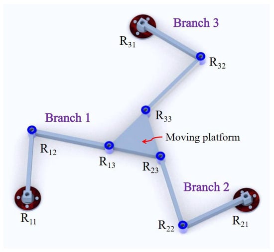
Figure 1.
The rigid 3-RRR parallel mechanism.
In Refs. [32,33], the small bending deformation of the cantilever beam is equivalent to the rotation of flexible revolute joints connected in series, which corresponds to the pseudo-rigid-body model. The deformation of a longer cantilever beam can be equivalent to the rotation of two serially connected revolute joints, which are located at one-half and one-third of the distance from the two ends of the beam. Meanwhile, the deformation of a shorter cantilever beam can be regarded as the rotation of a revolute joint located at its midpoint, as shown in Figure 2.
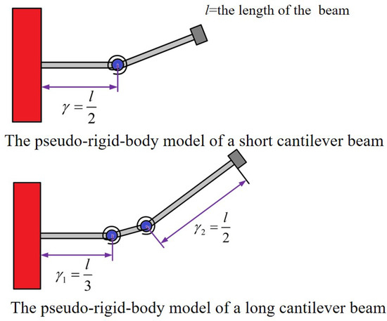
Figure 2.
The pseudo-rigid-body model of cantilever beam.
Therefore, two cantilever beams with different lengths are used to replace the revolute joints in the branch under the initial configuration, where the short beam is equivalent to one revolute joint and the long beam is equivalent to two revolute joints. To avoid increasing costs due to excessively long piezoelectric beams, piezoelectric sheets are attached to short beams to form piezoelectric composite beams (PBs). These two beams of different lengths connected together can be called an L-shaped bent beam. One end of the piezoelectric sheet is fixed to the base, and wires are led out from the fixed end. The primary function of the long beam is to transmit the inertial force of the oscillator; hence, it is referred to as the transmission beam (TB). To avoid excessive uncertainty, it is specified that the length of the long beam is twice that of the short beam. The final topology structure of the C-MVEH is obtained and shown in Figure 3. The black solid line represents the designed planar 3-RRR mechanism, which is the proposed C-MVEH’s structure, with green annotations indicating its dimensions. The red dashed lines represent the corresponding pseudo-rigid-body model, while purple annotations denote its dimensions.
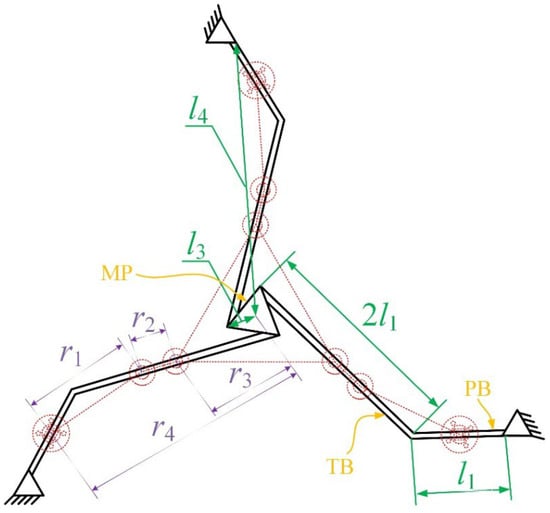
Figure 3.
Topology structure of the MVEH.
As indicated in Figure 3, l1, r3, and r4 can be regarded as independent variables, with all other structural dimensions being determinable therefrom. Specifically, l1 regulates the length of the PB, while r4 dictates the overall size of the C-MVEH. It is noteworthy that r3 merely denotes the size of the moving platform rather than that of the oscillator. The relationship between the dimensions of the 3-RRR compliant mechanism and those of its pseudo-rigid-body model can be obtained:
2.2. Motion and Low-Frequency Performance
During energy harvesting, the motion of the oscillator drives the piezoelectric composite beam to bend reciprocally so as to obtain a continuous voltage output. Intuitively, when the excitation frequency is constant, the greater the responsive deformation of the piezoelectric composite beam, the higher the output voltage. However, the deformation of the PB is indirectly induced by the responsive amplitude of the oscillator through the TB in the C-MVEH; thus, the transmission performance of the oscillator’s motion to the PB’s deformation directly affects the output voltage. In rigid mechanisms, the Jacobian matrix is often used to measure motion flexibility, which reflects the transmission capacity of the driving joint motion to the moving platform motion. Based on the pseudo-rigid-body model theory, the motion flexibility of rigid mechanisms can be applied to the C-MVEH to evaluate the transmission performance of oscillators’ motion to PBs’ deformations. However, merely considering motion is insufficient; the C-MVEH should also require a small driving force so as to ensure continuous deformation of the PBs under a small excitation force. The force manipulability index [34,35] is used to measure the transmission qualities of velocity and force, including the velocity manipulability and force manipulability indices, as well as the distance to singularity in rigid parallel mechanisms. In other words, the higher the index, the better the mechanism’s motion and force transmission capabilities. Therefore, the force manipulability index is employed to evaluate the energy transmission efficiency of the proposed C-MVEH, as the index can simultaneously characterize the motion flexibility and force transfer performance of both rigid and compliant parallel mechanisms. Additionally, because vibration excitations in the environment are low-frequency, low-frequency characteristics constitute one of the critical performance aspects of a vibration energy harvester. Under the premise of determining the oscillator structure as well as the width and thickness of the beams, the influence of dimensional parameters on the working frequency is analyzed, ultimately leading to the design of a C-MVEH with potential for engineering applications.
- Flexibility performance
Before establishing the force manipulator model, it is necessary to perform motion analysis on the pseudo-rigid-body model to obtain the Jacobian matrix. According to geometric relationships, it can be concluded that
where:
where s represents the sine operation; c represents the cosine operation; is the rotation angle of the ith rotation pair in the pseudo-rigid-body model, corresponding to the deformation of the PB in the ith branch; is the rotation angle of the moving platform; x and y are the displacement of the moving platform; and is constituted by the angles between symmetric branches.
Taking the derivative of both sides of Equation (2) with respect to time, we obtain
where:
The Jacobian matrix for mapping the motion of the moving platform to the output joint in the pseudo-rigid-body model is
The force manipulator index is
Normalize the connecting beam lengths l1, r3, and r4 by
Based on the structural characteristics of the 3-RRR mechanism and considering the technical requirements for processing and assembly, the following constraints are applied:
The last three inequalities in Equation (8) are designed to constrain the coordination of the length scale of the rod so that no scale becomes too large. The force manipulability performance map under the constraint of Equation (8) can be obtained from Equation (5). For the convenience of comparative analysis, the map is presented together with the frequency map in the following.
- 2.
- Low-frequency performance
The natural frequency of the energy harvesting structure is a critical performance parameter. Only when the excitation frequency coincides with the natural frequency can the energy harvester output a relatively high voltage. The beam element is simplified as a massless beam, with the influences of damping and piezoelectric sheets neglected. The transfer matrix method for multi-body system dynamics is applied to analyze the dynamic characteristics due to its advantage of ease of programming. The influence of beam length on the dynamic characteristics of the C-MVEH is the core of this paper. Therefore, based on the determination of beam width, thickness, and oscillator mass, a dynamic model of the system is established. Considering the requirements of processing and assembly technology, the volume of the energy harvester should be moderate. Therefore, the thickness of the beam is 0.1 mm, the width is 15 mm, and the mass of the oscillator is 30 g. The schematic diagram of the discrete model for multi-body system dynamics is given in Figure 4.
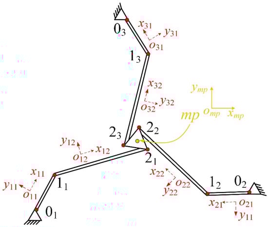
Figure 4.
Schematic diagram of discrete model for multi-body system dynamics.
The process of establishing the overall transmission model is presented in Appendix A. A homogeneous transfer equation according to the boundary conditions based on Equation (A8) is obtained:
According to the boundary conditions, the characteristic equation is
By solving Equation (10), the natural frequency of the system can be obtained.
2.3. Design of the C-MVEH
To make the resonant frequency of the proposed C-MVEH more compatible with low-frequency environmental excitations, the natural frequencies of the corresponding first three modes should be as low as possible. However, the resonant frequency of the system is collectively determined by numerous structural parameters, including but not limited to the length, thickness, and width of the connecting rod, as well as the oscillator mass. To ensure that the C-MVEH achieves both high motion and force transmission performance and a low resonant frequency, dimensional synthesis is performed herein. Specifically, under the conditions of a fixed oscillator and fixed thickness and width of the connecting beams, a performance map is developed to express how the beam length influences the maximum resonant frequency corresponding to the first three operating modes. It plots the performance map of dimension vs. third-order resonant frequency for different beam lengths, which, together with the force manipulator map in the initial posture, are presented in Figure 5.
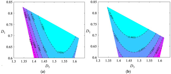
Figure 5.
Motion and low-frequency performance map: (a) the force manipulator map; (b) the third-order resonant frequency map (Unit: Hz).
From the performance map, it can be observed that the force manipulator index decreases as D3 decreases, which is attributed to the fact that a smaller D3 brings the mechanism closer to a singular configuration. From the frequency map, it is found that the maximum frequencies of the first three orders decrease as D1 and D3 decrease. This is because smaller values of these two parameters result in a larger overall size of the mechanism, leading to a reduction in stiffness. A set of dimensional parameters with better performance is selected from the two maps to determine the overall dimensions of the energy harvester, as depicted in Equation (11), and the corresponding first three natural frequencies are 7.4 Hz, 7.4 Hz, and 13.5 Hz.
Additionally, the 3-RRR mechanism has two translational and one rotational DOFs, and the C-MVEH cannot generate a rotational response when subjected to linear excitation. Therefore, an eccentric design is applied to the moving platform, resulting in a high adaptability of the C-MVEH to complex excitation environments. A small hole with a diameter of 4 mm was drilled out at a distance of 4 mm from the geometric center of the disk oscillator, resulting in a very small eccentricity. According to the D’Alembert principle, the oscillator would experience an inertial force and a very small moment of inertia under linear acceleration excitation. Therefore, during the vibration process, the oscillator undergoes translational and rotational coupled responses. The final structure is shown in Figure 6.
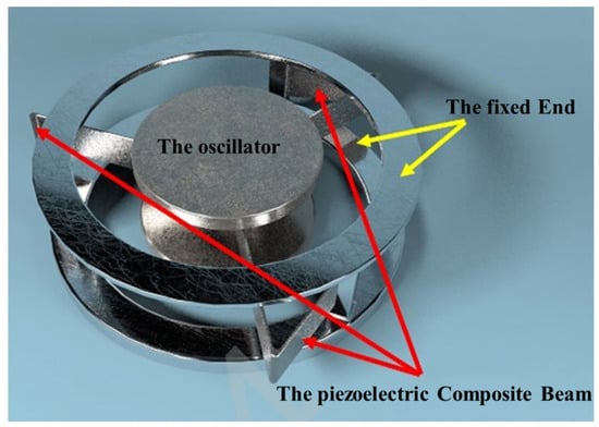
Figure 6.
The proposed C-MVEH.
3. Energy Harvesting Modeling
Considering that the mass of the PBs and TBs is much smaller than that of the oscillator, only the kinetic energy of the oscillator is taken into consideration. Therefore, the kinetic energy of the system is
where M is the equivalent mass matrix of the oscillator, xb is the base displacement, and xf is the response displacement of the oscillator relative to the base. It should be noted that a single dot above the displacement variable denotes its first derivative with respect to time, whereas two dots represent its second derivative.
The elastic potential energy of the system can be expressed as
where Jall is the Jacobin matrix mapping the motion of the moving platform to the rotation of each rotating pair and Ks is the diagonal matrix composed of the rotational stiffness of each joint in the pseudo-rigid-body model.
The piezoelectric complementary energy [36] can be expressed as
where Cp is a diagonal matrix composed of the equivalent capacitance of the piezoelectric sheet without external load, V is a vector composed of the electrode voltage of the piezoelectric beam, e31 is the piezoelectric charge constant, bp is the width of the PB, zm is the distance from the middle plane of the piezoelectric sheet to the neutral axis, Jp is the Jacobian matrix of the motion mapping from the oscillator to the rotational joint of the pseudo-rigid model of the PB, and kp is the bending stiffness of the piezoelectric flexible beam.
The dissipated energy of the system is divided into two parts. The first part is the structural damping of the mechanical system, and the second part is the connected load on the piezoelectric beam, expressed as
where cps represents a diagonal matrix composed of the equivalent damping and R is the external load.
Therefore, based on the Lagrange equation, the dynamic model of the system is
where , is the magnetic flux of the circuit system, and , Kp is a diagonal matrix with diagonal element .
4. FEA and Experiment Analysis
4.1. FEA Analysis
To verify the value of the proposed energy harvester and the correctness of the established model, finite element simulation analysis of the natural frequencies and the open-circuit output voltage with a 10 MΩ external resistor connected is conducted using the commercial finite element analysis software Comsol 6.3. Apply the same 0.2 g harmonic acceleration excitation to the fixed end of the piezoelectric composite beam. The mesh type in the L-shaped beam area is hexahedral mesh, and the mesh in the contact area of the screw assembly is automatically and finely divided by the software. The dynamic characteristics and mechanical piezoelectric coupling simulations of the proposed C-MVEH are carried out separately. The first three orders of natural frequencies and modes are shown in Figure 7. The frequencies obtained by the simulation are consistent with those obtained by the transfer matrix method.
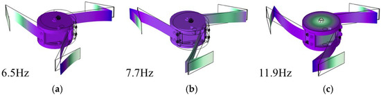
Figure 7.
The first three natural frequencies and modes of the system obtained from simulation. (a) The first-order resonant mode and frequency, (b) the second-order resonant mode and frequency, (c) the third-order resonant mode and frequency.
4.2. Prototype Development and Setup
The TB and the substrate of the PB are made of copper, and the oscillator is made of aluminum alloy. Other parts are fabricated by 3D printing, while the whole structure is assembled with threaded fasteners. The PB is composed of a PVDF sheet attached to a copper substrate, and the enameled wires are led out from the end using conductive silver adhesive. It should be pointed out that a large amount of adhesive is used in the production of the experimental prototype, which undoubtedly exacerbates the damping phenomenon of the system. Therefore, a relatively large equivalent damping ratio is applied. The internal resistance of the 10× probe of the oscilloscope is 10 MΩ. The output voltage of each branch is measured separately, which is equivalent to connecting a 10 MΩ resistor to the end of each branch. Due to limitations in the content of this paper, research on the optimal resistance load of the C-MVEH will be conducted in future work. The specific structural and performance parameters of the energy harvester are shown in Table 1.

Table 1.
Geometric and characteristic parameters of the C-MVEH.
The fabricated C-MVEH is fixedly installed on the exciter (DFT9020, Data Physics, Riverside, CA, USA), and the signal generated by the signal generator (DFT2705, ITECH, Suzhou, China) is amplified by a power amplifier to control the exciter. The enameled wire led out from the piezoelectric sheet is connected to a 10× probe of the oscilloscope (DS1104, Rigol, Suzhou, China). The oscilloscope model 10× probe has an internal resistance of 10 MΩ. The experimental test platform constructed is shown in Figure 8. The basic excitation type is harmonic acceleration, with the same peak value but different frequencies. Manual frequency scanning within the range of 5–15 Hz, with a 0.1 Hz step size near the resonance frequency domain and a 0.2 Hz step size in other areas, is applied. The output voltage values corresponding to each frequency step are then measured and recorded.
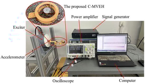
Figure 8.
The experimental test platform.
4.3. Uni-Directional Energy Harvesting Experiment
The curves of peak voltage with frequency under harmonic acceleration excitations of 0.2 g, 0.3 g, and 0.5 g are shown in Figure 9. It can be found that the peak voltages obtained from the theoretical model and FEA simulation show two wave crests, while the experimental data exhibit three wave crests. This is because the voltage near the first-order resonance peak is relatively small and does not stand out due to damping, which is consistent with the fact that the rotation angle of the R joint corresponding to the PB under the first-order modal shape is much smaller than that under the other two orders of modal shapes. Due to the neglect of the mass of the beam element and the idealization of the oscillator structure in the theoretical model, the resonance peak frequency is inconsistent with the simulation results, and the corresponding peak voltage is lower than in the simulation results. Due to machining and assembly errors in the developed physical prototype, the oscillator, flexible beam, and excitation direction do not lie in the plane where the C-MVEH is located. This results in some of the peak voltages obtained from the experiment being larger than in the theoretical and simulation results, which is particularly evident at the third-order resonance peak. For the overall result, the output voltage is approximately linearly related to the excitation acceleration, which indicates that the established model is correct.
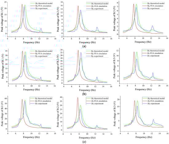
Figure 9.
Peak voltage–frequency curve in the initial direction: (a) 0.2 g acceleration; (b) 0.3 g acceleration; (c) 0.5 g acceleration.
4.4. Multi-Directional Energy Harvesting Experiment
A connection frame between the physical prototype and the exciter is designed with rotation holes for adjusting the posture. An experimental study on the energy harvesting performance within the range of −90° to +60° around the center of the C-MVEH is conducted, and the results are shown in Figure 10.
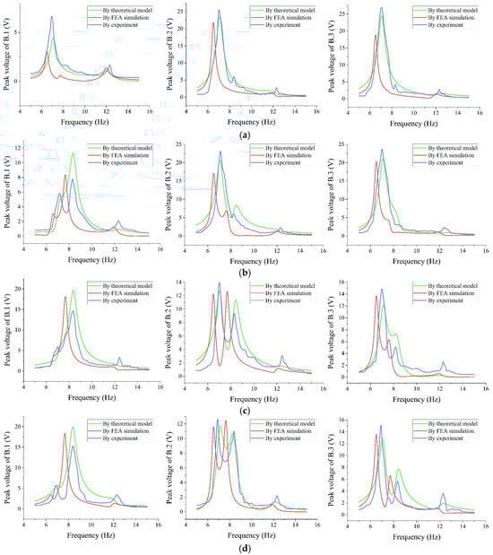
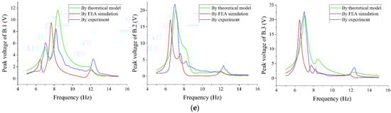
Figure 10.
Peak voltage–frequency curve in different directions: (a) along −90 degree direction; (b) along −60 degree direction; (c) along −30 degree direction; (d) along 30 degree direction; (e) along 60 degree direction.
It can be observed from Figure 10 that the output voltage of at least one branch can reach more than 6 V in all directions, and the total voltage of the three branches is above 20 V, which indicates that the C-MVEH can effectively collect energy from all directions in the plane. The voltage corresponding to the third resonance peak is relatively small in different directions because the mode corresponds to the rotation of the oscillator. Although the oscillator is designed with eccentricity, the torque generated under line excitation is small and not sufficient to drive the oscillator to significant rotation. In Figure 11, the power vs. frequency in different directions is given. It is easy to find that the proposed energy harvester has a high energy harvesting efficiency in different directions between the three resonance peaks. The experimental results show that even under small excitation, the designed C-MVEH can achieve stable and uniform energy harvesting within its plane, which indicates that it has practical value.
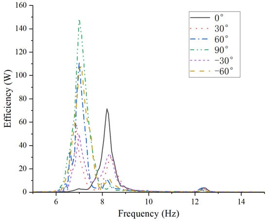
Figure 11.
The output power vs. frequency in different directions.
By comparing and analyzing the above results, it can be observed that due to the massless beam assumption, the first three natural frequencies obtained from theoretical calculation are slightly higher than those obtained from simulation analysis. This assumption also results in the theoretically calculated output voltage being lower than in the finite element simulation results. However, compared with these results, the convenience brought by the assumption of massless beams in the modeling process makes these minor differences acceptable. It can be considered that the first three orders of natural frequencies and the frequency response curves of the peak voltages of the proposed harvester are highly consistent, which confirms that the proposed C-MVEH can stably output a relatively high power when subjected to small in-plane excitations in multiple directions.
The variation in the total output power of the three branches with respect to the excitation direction and frequency under an acceleration of 0.2 g is given in Figure 11. It can be seen that the proposed energy harvester can achieve a maximum energy output power of 148 μW in different working directions and can achieve ideal energy collection efficiency between the three resonance peaks.
The designed C-MVEH can harvest energy in multiple directions in a plane. Comparisons with the existing compliant parallel structures [26,27,28] are given in Table 2. The piezoelectric material, size, and excitation amplitude applied in this paper are different. Although similar experimental results are obtained, they do not clearly demonstrate the superiority of the proposed C-MVEH. For example, the used oscillator is relatively light and has a small acceleration excitation, but the piezoelectric material used is PVDF, which has better energy harvesting performance than PZT material. Therefore, the output voltage obtained in the experiment has no significant advantage compared to previous works.
Table 2.
Comparisons with the existing compliant parallel harvesters.
5. Conclusions and Discussion
Based on the advantages of the compliant parallel mechanism, including easy miniaturization, being maintenance-free, and having diverse degrees of freedom, a C-MVEH derived from a 3-RRR compliant parallel mechanism is proposed in this paper. Through dimension optimizing, the transmission performance of the moving platform’s motion to the bending of the piezoelectric beam is improved. Meanwhile, the length of beams in the mechanism is optimized with the maximum working frequency. The two optimizations aim to achieve greater bending of the piezoelectric beam under small forces and displacements applied to the oscillator, thereby improving energy harvesting efficiency. Theoretical modeling, finite element simulation, and experimental research have been conducted. It can be found that the dynamic responses obtained by the three methods are highly consistent. The proposed C-MVEH can output peak electrical energy close to 150 μW under the excitation of 0.2 g acceleration from any planar directions within 6–13 Hz. The mechanical vibrations in the environment are mostly low-frequency vibrations, such as the base vibrations of high-power water pumps, fans, and large compressors, as well as the low-speed rotation of the rotors or eccentric blocks of jaw crushers and ball mills used in mines. The proposed C-MVEH has important application value in these scenarios.
In fact, although the proposed C-MVEH can collect energy in multiple directions, these directions are constrained within the plane of the energy harvester, limiting its application scenarios. Meanwhile, this work only qualitatively analyzes the deformation of piezoelectric composite beams under oscillator vibration, without considering the energy transfer performance of the transfer beam, resulting in suboptimal energy harvesting. Moreover, the load situation on the piezoelectric beam in the parallel structure is relatively complex, which includes axial force, lateral force, bending moment, and torque, and undergoes significant deformation. These situations will be studied in detail in our future work. The C-MVEH, incorporating the advantages of compliant parallel mechanisms, exhibits low stiffness in all working directions, making it more likely to work stably at low frequencies. The occurrence of multiple consecutive resonance peaks within a relatively narrow frequency band can also be regarded as a characteristic of broadband energy harvesting. Additionally, when considering nonlinear conditions such as large beam deformations or torsion–bending coupled deformations, the C-MVEH would exhibit internal resonance phenomena, thereby simultaneously possessing low-frequency, broadband, and multi-directional characteristics. Combining them with electromagnetic energy harvesting would result in higher energy-collection efficiency. Therefore, the C-MVEH holds tremendous application value and research potential in the field of energy harvesting.
Author Contributions
Methodology, S.Z.; Software, X.G.; Writing—original draft, S.Z.; Writing—review & editing, S.Z.; Visualization, X.G. All authors have read and agreed to the published version of the manuscript.
Funding
This research received no external funding.
Data Availability Statement
The original contributions presented in this study are included in the article. Further inquiries can be directed to the corresponding author.
Conflicts of Interest
The authors declare no conflicts of interest.
Abbreviations
The following abbreviations are used in this manuscript:
| C-MVEH | Compliant parallel multi-directional piezoelectric vibration energy harvester |
| MVEH | Multi-directional piezoelectric vibration energy harvester |
| PB | Piezoelectric composite beam |
| TB | Transmission beam |
Appendix A
The state vectors of each unit node in modal coordinates are
where the subscript j in the formula represents the jth branch, where j = 1, 2, 3, and i represents the ith unit node in the jth branch.
The transfer matrix of a planar massless flexible beam in a local coordinate system is
where E is the elastic modulus, I is the moment of inertia of the beam, A is the cross-sectional area of the beam, l is the length of the beam, the length of the PB is l1, and the length of the TB is 2l1.
The transfer matrix of the state vectors from a local frame to the global frame is
where is the coordinate transformation matrix and is the rotation angle of the pth beam in the jth branch at the global coordinate, which can be obtained from the kinematic equation.
The coordinate transformation matrix is
where . It should be noted that 0 denotes a matrix consisting of zeros, I denotes an identity matrix, and the subscripts indicate their dimensions, with some dimensions that have been clearly specified being omitted in this paper.
The motion platform is a rigid body with three input terminals and one output terminal, and the state vectors of its input and output terminals are
where
The transfer matrix is
By combining the above equations, the transfer equation of the system can be obtained:
where:
References
- Sharma, S.; Kiran, R.; Azad, P.; Vaish, R. A review of piezoelectric energy harvesting tiles: Available designs and future perspective. Energy Convers. Manag. 2022, 254, 115272. [Google Scholar] [CrossRef]
- Sah, D.K.; Amgoth, T. Renewable energy harvesting schemes in wireless sensor network: A survey. Inf. Fusion 2020, 63, 223–247. [Google Scholar] [CrossRef]
- Zhang, Y.; Li, S.; Wang, W.; Zen, P.; Li, C.; Ye, Y.; He, X. A review of electromagnetic wind energy harvesters based on flow-induced vibrations. Energies 2025, 18, 3835. [Google Scholar] [CrossRef]
- Yang, X.; He, X.; Li, J.; Jiang, S. Modeling and verification of piezoelectric wind energy harvesters enhanced by interaction between vortex-induced vibration and galloping. Smart Mater. Struct. 2019, 28, 115027. [Google Scholar] [CrossRef]
- Li, S.; Feng, Z.Q.; He, X.F.; Ye, Y.; Li, J. An in-plane omnidirectional flutter piezoelectric wind energy harvester. Mech. Syst. Signal Process. 2023, 200, 110637. [Google Scholar] [CrossRef]
- Le Scornec, J.; Guiffard, B.; Seveno, R.; Le Cam, V. Frequency tunable, flexible and low cost piezoelectric micro-generator for energy harvesting. Sensors Actuators A Phys. 2020, 312, 112148. [Google Scholar] [CrossRef]
- Iqbal, M.; Nauman, M.M.; Khan, F.U.; Abas, P.E.; Cheok, Q.; Iqbal, A.; Aissa, B. Multimodal hybrid piezoelectric-electromagnetic insole energy harvester using PVDF generators. Electronics 2020, 9, 635. [Google Scholar] [CrossRef]
- Shahruz, S.M. Design of mechanical band-pass filters for energy scavenging. J. Sound Vib. 2006, 292, 987–998. [Google Scholar] [CrossRef]
- Somkuwar, R.; Chandwani, J.; Deshmukh, R. Wideband auto-tunable vibration energy harvester using change in centre of gravity. Microsyst. Technol. 2018, 24, 3033–3044. [Google Scholar] [CrossRef]
- Lu, K.; Hu, R.C.; Wang, X.F.; Deng, Z. Multi-directional and ultra-low frequency energy harvester utilizing tunable buckled piezoelectric film. Mech. Syst. Signal Process. 2024, 210, 111137. [Google Scholar] [CrossRef]
- Stanton, S.C.; Mcgehee, C.C.; Mann, B.P. Nonlinear dynamics for broadband energy harvesting: Investigation of a bistable piezoelectric inertial generator. Phys. D 2010, 239, 640–653. [Google Scholar] [CrossRef]
- Dhote, S.; Li, H.T.; Yang, Z.B. Multi-frequency responses of compliant orthoplanar spring designs for widening the bandwidth of piezoelectric energy harvesters. Int. J. Mech. Sci. 2019, 157, 684–691. [Google Scholar] [CrossRef]
- Liang, H.; Hao, G.; Olszewski, O.Z.; Pakrashi, V. Ultra-low wide bandwidth vibrational energy harvesting using a statically balanced compliant mechanism. Int. J. Mech. Sci. 2022, 219, 107130. [Google Scholar] [CrossRef]
- Zhao, H.; Wei, X.; Zhong, Y.; Wang, P. A direction self-tuning two-dimensional piezoelectric vibration energy harvester. Sensors 2020, 20, 77. [Google Scholar] [CrossRef]
- Xu, J.; Tang, J. Multi-directional energy harvesting by piezoelectric cantilever-pendulum with internal resonance. Appl. Phys. Lett. 2015, 107, 213902. [Google Scholar] [CrossRef]
- Xu, J.W.; Tang, J. Modeling and analysis of piezoelectric cantilever-pendulum system for multi-directional energy harvesting. J. Intell. Mater. Syst. Struct. 2016, 28, 323–338. [Google Scholar] [CrossRef]
- Wu, Z.H.; Xu, Q.S. Design and development of a novel two-directional energy harvester with single piezoelectric stack. IEEE Trans. Ind. Electron. 2020, 68, 1290–1298. [Google Scholar] [CrossRef]
- Wen, S.H.; Wu, Z.H.; Xu, Q.S. Design of a novel two-directional piezoelectric energy harvester with permanent magnets and multistage force amplifier. IEEE Trans. Ultrason. Ferr. 2020, 67, 840–849. [Google Scholar] [CrossRef] [PubMed]
- Wu, Z.H.; Xu, Q.S. Design, fabrication, and testing of a novel 3-dof energy harvester with single piezoelectric stack. J. Mech. Des. 2019, 142, 063303. [Google Scholar] [CrossRef]
- Han, M.; Yang, X.; Wang, D.F.; Jiang, L.; Song, W.; Ono, T. A mosquito-inspired self-adaptive energy harvester for multi-directional vibrations. Appl. Energy 2022, 315, 119040. [Google Scholar] [CrossRef]
- Shi, G.; Tong, D.; Xia, Y.; Jia, S.; Chang, J.; Li, Q.; Wang, X.; Xia, H.; Ye, Y. A piezoelectric vibration energy harvester for multi-directional and ultra-low frequency waves with magnetic coupling driven by rotating balls. Appl. Energy 2022, 310, 118511. [Google Scholar] [CrossRef]
- Liu, D.; Al-Haik, M.; Zakaria, M.; Hajj, M.R. Piezoelectric energy harvesting using L-shaped structures. J. Intell. Mater. Syst. Struct. 2018, 29, 1206–1215. [Google Scholar] [CrossRef]
- Zhou, S.; Hobeck, J.D.; Cao, J.; Inman, D.J. Analytical and experimental investigation of flexible longitudinal zigzag structures for enhanced multi-directional energy harvesting. Smart Mater. Struct. 2017, 26, 035008. [Google Scholar] [CrossRef]
- Hu, G.; Liang, J.; Lan, C.; Tang, L. A twist piezoelectric beam for multi-directional energy harvesting. Smart Mater. Struct. 2020, 29, 11LT01. [Google Scholar] [CrossRef]
- Liu, X.J.; Chen, R.W. Energy conversion efficiency of rainbow shape piezoelectric transducer. Chin. J. Aeronaut. 2012, 25, 691–697. [Google Scholar] [CrossRef]
- Chen, R.; Ren, L.; Xia, H.; Yuan, X.; Liu, X. Energy harvesting performance of a dandelion-like multi-directional piezoelectric vibration energy harvester. Sensors Actuators A Phys. 2015, 230, 1–8. [Google Scholar] [CrossRef]
- Wei, X.; Zhao, H.; Yu, J.; Zhong, Y.; Liao, Y.; Shi, S.; Wang, P. A tower-shaped three-dimensional piezoelectric energy harvester for low-level and low-frequency vibration. Int. J. Precis. Eng. Manuf. Technol. 2020, 8, 1537–1550. [Google Scholar] [CrossRef]
- Xing, J.; Ji, X.; Wu, J.; Howard, I. A body hair-inspired multi-directional piezoelectric energy harvester with spatial internal resonance effect. J. Sound Vib. 2024, 589, 118543. [Google Scholar] [CrossRef]
- Bao, B.; Zhou, S.; Wang, Q. Interplay between internal resonance and nonlinear magnetic interaction for multi-directional energy harvesting. Energy Convers. Manag. 2021, 244, 114465. [Google Scholar] [CrossRef]
- Cao, D.-X.; Lu, Y.-M.; Lai, S.-K.; Mao, J.-J.; Guo, X.-Y.; Shen, Y.-J. A novel soft encapsulated multi-directional and multi-modal piezoelectric vibration energy harvester. Energy 2022, 254, 124309. [Google Scholar] [CrossRef]
- Zhang, S.; Liu, J.; Ding, H.; Gao, G. A novel compliance modeling method for compliant parallel mechanisms and its application. Mech. Mach. Theory 2021, 162, 104336. [Google Scholar] [CrossRef]
- Su, H. Mobility analysis of flexure mechanisms via screw algebra. J. Mech. Robot. 2011, 3, 041010. [Google Scholar] [CrossRef]
- Pei, X.; Yu, J.; Zong, G.; Bi, S. An effective pseudo-rigid-body method for beam-based compliant mechanisms. Precis. Eng. 2010, 34, 634–639. [Google Scholar] [CrossRef]
- Wu, J.; Wang, J.; Wang, L.; You, Z. Performance comparison of three planar 3-DOF parallel manipulators with 4-RRR, 3-RRR and 2-RRR structures. Mechatronics 2010, 20, 510–517. [Google Scholar] [CrossRef]
- Yang, C.; Ye, W.; Li, Q.C. Review of the performance optimization of parallel manipulators. Mech. Mach. Theory 2022, 170, 104725. [Google Scholar] [CrossRef]
- Yuan, G.; Zhuo, S.P.; Wang, D.H. Nonlinear arbitrary-directional broadband piezoelectric vibration energy harvester using 3-DOF parallel mechanism. Smart Mater. Struct. 2019, 28, 085016. [Google Scholar] [CrossRef]
Disclaimer/Publisher’s Note: The statements, opinions and data contained in all publications are solely those of the individual author(s) and contributor(s) and not of MDPI and/or the editor(s). MDPI and/or the editor(s) disclaim responsibility for any injury to people or property resulting from any ideas, methods, instructions or products referred to in the content. |
© 2025 by the authors. Licensee MDPI, Basel, Switzerland. This article is an open access article distributed under the terms and conditions of the Creative Commons Attribution (CC BY) license.