Abstract
This study evaluates energy conversion and heat transfer in a germicidal chamber employing gold nanorods (AuNRs) irradiated with an infrared laser (808 nm, 0.8 W) to generate heat via localized surface plasmon resonance. The investigation focused on the preliminary selection of chamber materials and the geometry of the bottom surface supporting the AuNRs as the heat source in a photothermoablation application. A one-way multiphysics and multiscale approach was applied, integrating nanoscale heating phenomena with a macroscale fluid and heat flow. The validated 2D numerical model shows satisfactory agreement with experimental data and is suitable for further design analyses. Computational Fluid Dynamics (CFD) simulations were conducted to determine temperature and entropy distributions, mean and maximum temperatures, and Nusselt numbers, allowing the assessment of the energy conversion process under different configurations and AuNR dimensions. The results indicate that a configuration with a gradually descending stepped structure enhances interactions between nanoparticles and the fluid, increasing the internal energy and producing elevated temperatures. Under optimal conditions, a temperature rise of approximately 75 °C was achieved. These findings demonstrate that integrating material selection, surface geometry, and nanoparticle absorbance optimization can significantly improve the efficiency of bacterial inactivation in germicidal chambers. This study provides a framework for future investigations on fully three-dimensional multiscale and multiphysical modeling, as well as a targeted AuNR design to maximize the thermal performance.
1. Introduction
Light-based germicidal chambers are not a novel concept in the literature [1,2]; however, the effective physical inactivation of bacteria is becoming increasingly important as resistance to chemical agents continues to develop in natural environments [3,4]. It has been well established for decades that ultraviolet (UV) radiation can effectively modify the DNA and RNA nucleotides of bacteria and lead to irreversible damage to pathogenic cells [5,6].
Dedicated chambers for bacteria inactivation are based on the localized plasmonic heating effect that occurs in metallic nanoparticles, including gold nanoparticles (AuNPs), when they are irradiated with a laser whose wavelength is close to the resonance peak of nanoparticles. This matching frequency induces a heating process that enables efficient bacterial inactivation [3,4].
In contrast, electromagnetic radiation in the microwave range induces heating through molecular vibration excitation. Elevated temperatures can efficiently sterilize most surfaces by causing thermal stress within pathogens, leading to protein denaturation or oxidative damage [7,8].
Recently, the inactivation of pathogens using white light has attracted growing interest due to its functionality, safety, and effectiveness. In this context, the incorporation of metallic nanostructures has emerged as a promising strategy to enhance the energy conversion efficiency compared to conventional heating methods. For instance, Petronella, et al. [9] demonstrated the use of antibody-functionalized gold nanorod arrays for the Escherichia coli inactivation process in aqueous media, while Méndez-Pfeiffer et al. [10] reported the photoactivation of gold and silver nanoparticles under white light leading to bacterial cell damage in both E. coli and Staphylococcus aureus.
Nevertheless, the optimization of heat transfer processes remains a sort of a challenge due to a local temperature increase [11,12]. The efficiency of pathogen inactivation could be further enhanced by intensifying convective heat transport and optimizing the shape of the system in chamber configurations [13,14]. The existing literature lacks complete studies that combine these two aspects, thermal optimization and structural design, respectively, which could yield a cost-effective and fully integrated approach to water decontamination.
In terms of the temperature increase of a specific material, it is important to optimize the dimensions of nanoparticles, which, when fitted into the absorption peak of a given wavelength, can convert a larger proportion of electromagnetic energy into heat [15,16].
Moreover, the Nusselt number is commonly used as a parameter characterizing the intensity of the heat transfer. By definition, a convective heat transfer is much stronger than a conductive one. Therefore, a higher Nusselt number indicates more efficient or intensified heat transport. Several studies have already investigated this phenomenon [17,18,19,20]. Particular attention should be given to processes in which heat generation is induced by an external source, described mainly as dissipative heat losses.
Interestingly, similar to the system considered in the present study, the investigation of the Nusselt number in [21] focused on a bottom-heated configuration with a constant-temperature boundary condition imposed at the lower wall. Although several natural convection models were compared, that study did not consider forced convection boundary conditions. Moreover, the heated surface was assumed to be perfectly smooth, an assumption that becomes increasingly restrictive at the micro- and nanoscale. In the broader literature, the Nusselt number is frequently analyzed for various chamber geometries in which nanoparticles are dispersed within the working fluid to form nanofluids, often in conjunction with magnetic field effects [22]. In the authors’ previous work, the Nusselt number was employed to assess the effect of the chamber base geometry, while the base material remained unchanged. In the presented Nusselt number results, only two types of base configurations and variations in the chamber wall material were evaluated [23]. In many cases, increases in the Nusselt number are typically accompanied by a higher flow resistance and pressure drops [24,25]. This behavior is not observed in the present study, as the nanoparticles are immobilized on the bottom surface rather than suspended in the fluid, and all fluid motion arises solely from buoyancy-driven natural convection.
None of these studies, however, examined the behavior of nanoparticles deposited on the surface. This aspect represents a novel area in the literature, with only a few related studies reported until now. In these works, the wall is modeled with slip boundary conditions where different physical models are incorporated. For instance, in [26,27], the Smoluchowski temperature jump and Maxwell velocity slip at the walls were implemented to represent thermal and shear stresses under fluid flow. In contrast, in [28], the magnetothermal effect in AuNPs was assumed to influence thermal properties analogously to that observed in nanofluids. Furthermore, in the authors’ previous study [29], the effect of the capping agent on laser-irradiated AuNRs was discovered to be significant and was modeled via the Marangoni stress slip boundary condition, which determines the surface tension coefficient of the entire AuNR. According to a review of existing experimental, theoretical, and numerical work, some slippage occurs between the material and the fluid and is related to the interaction between these materials [30]. As the characteristic dimensions of the system increase, the slip effects at the phase boundary become negligible [31]. Despite the omission of the aforementioned interfacial conditions, the present work addresses a multiscale process spanning the transition from the nanoscale to the macroscale. At the nanoscale, electromagnetic waves are converted into heat on the AuNRs as a result of the plasmon-induced vibrational excitation of the deposited nanoparticles. This energy is subsequently transferred to the supporting solid substrate, followed by the heating of the adjacent water layer through conduction. At the macroscale, heat is transported into the bulk fluid and gives rise to buoyancy-driven convective motion. Consequently, the overall phenomenon can be classified as multiphysical, involving electromagnetic energy absorption, heat transfer, and fluid flow.
In the literature, multiscale and multiphysics approaches are recognized as essential in a range of engineering applications. One example is powder-based laser welding, where such modeling is required to accurately predict the properties of the resulting weld [32]. In this process, the nanoscale is associated with the size of the powder particles, while the laser-induced melting of both the powder and the joining material leads to the weld formation, whose mechanical properties must ultimately be assessed at the macroscale. Closely related phenomena occur in metal additive manufacturing processes [33], where powders are deposited as successive layers; although the specific physical mechanisms differ, the underlying multiscale and multiphysical nature of the laser–matter interaction and heat transfer is analogous. Multiphysical modeling is also crucial in photocatalytic reactors, where electromagnetic radiation induces chemical reactions at catalytic surfaces [34]. In such systems, the catalytic layer introduces nanoscale effects, while their integration into macroscopic operating conditions enables the optimization of the overall reactor design.
Furthermore, the incorporation of materials with nanoscale functional substructures often leads to the development of new classes of functional materials, whose effective properties emerge only when a broad spectrum of physical phenomena is considered [35]. Beyond numerical modeling, experimental investigations play a crucial role in the characterization of newly developed structures, enabling meaningful connections between nanoscale mechanisms and macroscale performance relevant to future applications [36,37]. In addition to engineering applications, multiscale and multiphysics modeling has become increasingly important in medicine, where advanced therapeutic techniques employ nanoparticles in both chemotherapy [38] and thermotherapy [39]. Drug administration itself constitutes an inherently multiscale process, in which particular promise lies in the analysis of targeted drug delivery [40] and in the investigation of multicomponent therapeutic strategies, where several coupled physical processes collectively determine treatment efficacy [38].
However, the techniques presented require significant computing power and obtaining results is time-consuming. Taking the above into account, the one-way modeling of the transition from nano- to macroscale is implemented. With respect to the physics of the process, the mutliphysical approach is selected where the result from the model of the conversion of electromagnetic waves into heat by Radomski, et al. [29] is most effective.
1.1. Research Questions and Considered Cases
Based on the literature survey, it was concluded that the following research questions have yet to be answered:
- How does the shape of the chamber bottom affect the temperature contours?
- Which materials available for chamber production will be beneficial in terms of achieving the highest mean temperature?
- Can the Nusselt number indicate directions for the development of a new type of bactericidal chamber?
- What type of gold nanorods will be most advantageous, and is there a correlation between absorption for a given wavelength and the temperature increase in the system?
The objective of this study is to develop a chamber design that is sufficiently simple to enable the practical application of nanoparticles while simultaneously allowing efficient heat transfer to the water, with minimal heat losses to the surroundings. Figure 1a shows the primary concept of the germicidal chamber with a gradually ascending stepped heat source configuration (Case 1, namely: C1); on the other hand, Figure 1b describes a modified shape with a gradually descending configuration (Case 2, namely: C2). Additionally, Figure 1 presents the main components of the germicidal chamber with a schematic diagram illustrating the hypothesized flow patterns and heat transfer mechanisms in C1—Figure 1a and C2—Figure 1b. On gold NP, electromagnetic waves are converted into heat (—red arrows), which is subsequently conducted through the base structure to an insulated container (—green arrows) filled with water (—blue arrows) to test the performance of the device. An air layer is present above the water surface.
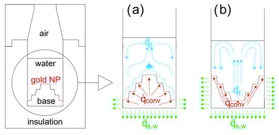
Figure 1.
Conceptual drawing of the analyzed system where step edge in red color represents surface with AuNRs which connects multiscale and multiphysics processes: (a) gradually ascending stepped heat source case (C1); (b) gradually descending stepped heat source case (C2).
To address the research questions posed in this study, an experimental investigation was conducted to validate the 2D numerical model. Subsequently, numerical simulations were performed for two baseline configurations (C1 and C2) incorporating various AuNRs applied to the base surface.
1.2. Research Hypothesis
By carefully designing the geometry of the bottom surface, it is possible to enhance the distribution of this heat, ensuring that the entire fluid volume reaches temperatures sufficient for bacterial inactivation. The geometry of the germicidal chamber with gold nanorods (AuNRs), particularly the shape and arrangement of the internal cavities, significantly influences the performance of heat transfer processes within the device. Analyzing these geometric features is essential to ensure that heat is evenly distributed and retained within the chamber, thereby maximizing the temperature increase and, in the further perspective, also bacterial inactivation.
1.3. Novelties and Contributions
This study explores the impact of the chamber geometry on the heat transfer efficiency, temperature increase, and, in the further perspective, also bacterial inactivation, focusing on the design and optimization of the bottom surface shapes used in these chambers.
The novelty of this work lies in its detailed exploration of bottom surface geometry’s role in optimizing the heat transfer within the chamber. By shifting the focus from material properties to geometric optimization, this study provides new insights into the design of a more effective chamber for bacterial inactivation, offering a pathway toward enhanced thermal management biomedical applications.
To perform this analysis, we employ a one-way multiphysical and multiscale modeling framework that has been developed and validated in our previous work [29]; however, in the case of another geometry. In this framework, three characteristic length scales are distinguished, namely: (1) the nanoscale related to the AuNRs dimensions; (2) the microscale associated to the wavelength of the electromagnetic radiation emitted by the laser; and (3) the macroscale of the chamber in which heat is distributed. The nanoscale optical–thermal model provides a volumetric heat source that is used as the input in the macroscale CFD simulation, without feedback from the macroscopic temperature field to the nanoparticle optical properties. The problem is thus treated in a multiphysical context, combining: (1) optics, through the description of absorbance; (2) electromagnetism, through the conversion of electromagnetic energy into heat via localized surface plasmon resonance; and (3) thermodynamics, through the resulting enhancement of heat transfer within the chamber.
1.4. Organization of the Article
In Section 2, this article presents the methodology of the research conducted. It has been divided as follows: ‘Section 2.1. Geometry and selected materials’: in addition to specifying the specific dimensions, the materials used to construct the chamber and applied in numerical calculations are listed; ‘Section 2.2. Properties of materials used in simulations’, which lists the relevant physical parameters necessary for the calculations; ‘Section 2.3. One-way multiphysical and multiscale approach’: the approach is discussed; ‘Section 2.4. Fluid flow and heat transfer equations’: refers to the mass, momentum, and energy balance in steady-state CFD calculations; ‘Section 2.5. Boundary conditions in macroscale’, with conditions ensuring that different dimensions of AuNRs are taken into account; ‘Section 2.6. Numerical model validation’, with a description of cases validated in the literature to date concerning the irradiation of gold nanoparticles; and the ‘Section 2.7. Definition of Nusselt number and CFD simulation’, where other information necessary to obtain the results is considered.
2. Methodology
2.1. Geometry and Selected Materials
The geometry used in this study consists of solid and fluid parts designed to hold 2 mL of water. The chamber includes two primary components: the walls of the chamber, constructed from Polyethylene Terephthalate Glycol (PETG), and the heat source, which can be made from either PETG or PolyDiMethylSiloxane (PDMS). The choice of materials is crucial, as it influences the thermal behavior and heat transfer characteristics. The geometry was chosen to improve the heat and mass transfer in water. The bottom of the chamber was shaped to resemble a rib. At the same time, a sufficiently large area was left to apply gold nanoparticles onto which light rays fall perpendicular to the entire illuminated surface (Figure 2a). The second chamber is simply inverted relative to the first (Figure 2b).
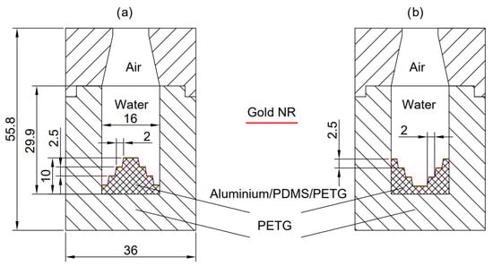
Figure 2.
Dimensions of geometry in [mm] and materials of germicidal chamber for (a) C1 and (b) C2.
The interior diameter of the chamber was assumed to be 16 mm. In turn, the insulation reached 36 mm in diameter and 45 mm in height, where the height of the first part was 29.9 mm. In addition, the base for the heat source with AuNRs was 10 mm high, with a pitch of 2.5 mm each. The diameter of the saucer varied by 4 mm, successively obtaining 4, 8, and 12 mm.
2.2. Properties of Materials Considered in Simulations
Table 1 summarizes the properties of the fluids (air and water) used in simulations. These properties include density, specific heat capacity, thermal conductivity, and dynamic viscosity, which are essential for determining how heat is transferred inside the chamber. The thermophysical properties of water were treated as temperature-dependent. In particular, water density was modeled using a polynomial correlation derived from IAPWS-based formulations for liquid water [41], as summarized in Table 1. This approach was adopted to avoid potential inaccuracies associated with the Boussinesq approximation under conditions of large temperature-induced density variations.

Table 1.
Properties of fluids in the calculation area.
Table 2 summarizes the density and thermophysical properties of the solid materials constituting the chamber structure, namely PDMS, aluminum, gold, and PETG, based on literature data [42,43,44].
Table 2.
Properties of the solids used to build the chamber.
The selection of materials used in the present study was guided by both physical considerations and experimental constraints. In particular, the heat source base materials were chosen to represent contrasting thermal management strategies rather than to identify a single optimal solution. As summarized in Table 2, aluminum and PDMS exhibit strongly differing thermal conductivities, equal to 205 W·m−1·K−1 and 0.11 W·m−1·K−1, respectively. Aluminum promotes rapid lateral heat spreading within the base, leading to stronger coupling with buoyancy-driven convection and enhanced heat redistribution toward the chamber walls. In contrast, PDMS limits lateral heat diffusion and favors localized heat accumulation in the vicinity of the AuNR-coated surface, thereby promoting thermal storage and higher local temperatures.
In addition to these conceptual considerations, practical limitations related to the experimental setup were taken into account. During the model calibration and validation stage, the experimental chamber was fabricated entirely from PETG, which served simultaneously as the base material and as thermal insulation. A comparison of the thermophysical properties of PETG and PDMS indicates that these materials exhibit similar thermal characteristics, with differences in volumetric heat storage capacity at the order of 7%. This similarity supports the use of PETG in the experimental configuration while maintaining consistency with the numerical analysis.
Following the initial comparison between aluminum and PDMS, the remaining parametric studies were conducted using PDMS and PETG as the heat source base materials in order to isolate the effects of base geometry and insulation material. In these cases, PETG was used as the insulation layer, as it exhibits sufficiently low thermal conductivity while also being well suited for additive manufacturing. This approach enables a systematic investigation of the coupled effects of material properties and geometric configuration on heat retention, convection patterns, and overall thermal performance, thereby providing a framework for future design-oriented studies.
2.3. One-Way Multiphysical and Multiscale Approach
As already mentioned in the introduction, this issue is considered in the context of the one-way multiphysical and multiscale approach. The total energy converted from electromagnetic waves into heat by the gold nanorods was calculated using [29]:
where is absorption coefficient of AuNPs []; means number of nanoparticles with [-]; represents initial intensity of laser [W]; gives reflection coefficient beyond AuNRs [-]; defines interaction length of the —particle [m]; is refractive index of gold [-]; means refractive index of the water [-]; and represents incident angle [rad].
The model assumes that the laser beam strikes the nanoparticles perpendicularly, which means that term can be neglected. Thus, the equation in the one-way multiphysical and multiscale approach describing the transition from the nano- to the macroscale and capturing the electromagnetic phenomenon with thermal processes is expressed as:
where describes a factor allowing transition from a 3D experiment to simplified 2D geometry and is interaction length of the —particle which can be defined as follows:
in which represents size of the —particle (for AuNRs it is diameter) and gives capping agent thickness.
The precise number of nanoparticles () cannot be determined, as their concentration is of the order of 1023 nanoparticles per m3. In addition, it was assumed that a single layer was placed on the PEGT/PDMS surface of the bactericidal chamber. Therefore, a simplified assumption to the mathematical model was introduced, in which the nanoparticle size distribution was approximated by a normal (Gaussian) curve. It should be noted, however, that this assumption idealizes the model by a uniform spatial distribution of nanoparticles. However, it is possible to measure and calculate absorbance, which is a measure of radiation absorption:
in which represents the intensity absorbed by the environmental material of AuNRs and means the intensity absorbed by the gold nanorods. It is noteworthy that term is included in Equation (2), and its form is as follows:
Furthermore, the absorption coefficient of AuNPs () appearing in Equation (1) both as a parameter proportional to and in the power of the exponential function can be expressed as:
where means nanoparticles concentration, which takes into account distance between nanorods; represents incident wavelength; includes imaginary part of a complex expression; defines polarizability of the -particle; and is effective polarizability of the -particle. The parameters related to nanoparticles that need to be included in the model are listed in Table 3. Other details of the multiscale approach allowing for the transition from the nanoscale (where the characteristic dimensions relate to nanoparticles) through the microscale (where the characteristic dimension relates to electromagnetic waves) to the macroscale (where the characteristic dimensions relate to the chamber, cf. Figure 1) are provided in the work of Radomski et al. [29].
Table 3.
Properties of AuNPs used in calculations.
To calculate the accurate number of nanoparticles, the following factors must be taken into account: expected size (diameter) of nanorods, size error, expected length of nanorods, length error, distance between nanorods, capping agent thickness, and nanoparticle concentration. Details on mathematical models and their calibration for different types of nanoparticles are presented in the works of Radomski, et al. [29] and Koulali, et al. [15].
This paper uses three types of nanoparticles mentioned in the introduction. In general, the number of nanoparticles can be estimated based on the concentration or Fill Factor, i.e., the surface filling coefficient. This is usually carried out using various techniques. In the experimental case, UV-Vis spectroscopy and TEM/SEM microscopy imaging can be used.
Properties of AuNRs used in calculations of the one-way multiphysical and multiscale approach is gathered in Table 3. In the model, each nanorod was separated by a distance of 23.13, 24.45, and 25.65 nm, respectively. The nanorod dimensions were assumed to follow the same size distribution, with deviations of ± 2 nm in diameter and ± 5 nm in length. The capping agent, CTAB, was modeled with a (shell) thickness of 3.5 nm and a refractive index of 1.435. The incident angle of laser beam was fixed at 0°.
The reflection coefficient in this wavelength for water, air, and PDMS was calculated using full Fresnel’s formulae, and they equal 1.000278761220420, 1.32808408996175, and 1.48416354270000, respectively. These are coefficients for a wavelength of 808 nm. The refractive indices of gold were determined based on electrical conductivity. The values were selected based on the Drude–Lorentz model, which has the closest results to those measured experimentally. Issues related to the macroscale are addressed in the following subsections.
In the present configurations, the AuNR layer is not resolved as discrete particles in the CFD mesh. Instead, following our previous work [29], it is represented in a homogenized manner as an equivalent continuous gold film with a thickness of 23 nm attached to the selected wall of the chamber (gold NR—Figure 2). At the nanoscale, the optical–thermal model uses the gold properties (optical absorption, thermal properties, and rod dimensions) to compute the absorbed power per unit volume within this equivalent film. This absorbed power is then integrated across the film thickness to obtain the net surface heat flux at the AuNR–water interface. This surface heat flux provides the link between the nanoscale description and the macroscale CFD model and is used as the thermal boundary condition on the selected walls in the simulations described in Section 2.7.
2.4. Fluid Flow and Heat Transfer Equations in Macroscale
The fluid flow and heat transfer in the chamber is described by the Navier–Stokes equations and the energy equation [45]. The density in these equations is temperature-dependent, reflecting the effects of thermal expansion on the fluid dynamics within the device and natural convection processes. The momentum equation, energy equation, and continuity equation were used to model the behavior of air and water within the chamber. Continuity equation can be defined as follows [45]:
where is velocity vector of fluids (water or air) [ms−1], expresses density [], refers to fluids constituting a modelled mixture [-], corresponding to water and air, and means divergence [m−1]. Equation (7) ensures mass conservation in the flow of the fluid (air or water). Furthermore, due to negligible pressure changes, air can be treated as an incompressible fluid.
Momentum equation is given by [45]:
where is the pressure for air or water [Pa], means gradient [m−1], represents body forces per unit volume of fluids such as gravity [kgm−2s−2], defines viscous stresses [Pa], and gives the cross product [-]. Equation (8) describes the balance of forces acting on the fluid, accounting for the effects of pressure (), influence of viscous stresses (), and external fields like gravity-inducing gravitational acceleration ().
Energy equation may be extended to include the contribution from the gold nanoparticle heat source [46]:
where represents the velocity field [ms−1], means the temperature of fluids [K], is the specific heat capacity at constant pressure , defines the thermal conductivity [Wm−1K−1], and means heat sources or sinks [Wm−3]. Equation (9) models the energy conversion within the fluid, including convective heat transfer conduction , and the heat generated by laser-irradiated AuNPs (). Effects related to slip [46] and temperature jumps [47] have been neglected, due to the dimensions of the system. A laminar model of flow was used due to low velocity values.
2.5. Boundary Conditions in Macroscale
The boundary conditions for the CFD simulations include the heat flux at the heat source, mixed convection/radiation conditions at the upper wall, and heat flux continuity at fluid–solid interfaces. Figure 3 represents the boundary conditions used in the calculations for the following analysis cases. It should be noted that such boundary conditions as the heat transfer coefficient and the power ( = 0.8 W) of the electromagnetic radiation source were constant. A power of = 0.8 W was selected because it will be the maximum laser power available in the future experimental study that maintains power stability and beam distribution during long exposure.
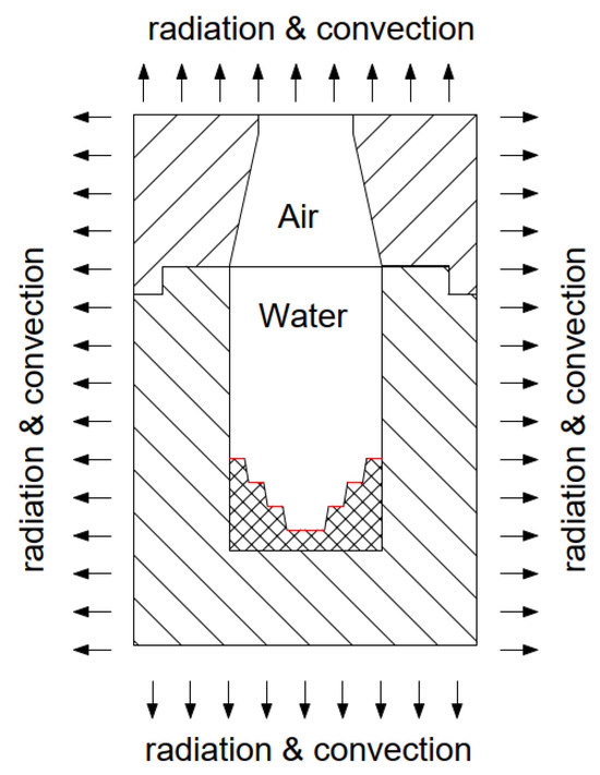
Figure 3.
Boundary condition in gradually descending stepped structure, where step edge in red color represents surface with AuNRs which connects multiscale and multiphysics processes.
The thermal boundary condition of this area can be described as heat flux [48]:
where represents the thermal conductivity of solid [Wm−1K−1] and means the temperature gradient for solid [K]. Therefore, refers to all solid materials listed in Table 2. The letter refers to fluids that come into contact at the boundary between the solid and the fluid. On the other hand, for fluid–solid interfaces, in the simplest form, the temperature continuity is described by the equation [48]:
where represents the temperature of solid [K], means the temperature of fluid [K]. For the outside walls of the device, the mixed convection/radiation condition can be implemented (see [46]):
where —external heat transfer coefficient [Wm−2K−1], —ambient temperature [K], —surface temperature of the wall [K], —Stefan–Boltzmann constant [Wm−2K−4], —emissivity [-], —external environment temperature [K], and —normal vector to wall.
Furthermore, the air–water separation is represented implicitly by the volume-fraction field, initialized to a flat, stationary interface at the nominal fill height. No mass transfer (evaporation/condensation) and no surface tension/Marangoni effects were included. The energy equation was solved by assuming thermal equilibrium between phases (single temperature contours).
2.6. Numerical Model Validation
The discussed model of energy conversion was previously validated in [29], where the influence of the resonance peak position and absorption spectra was examined for 15–55 nm gold nanorods dispersed in various media. Although those results did not directly relate to water solutions, it is assumed in the present work that the model remains representative and applicable to systems in which nanoparticles are deposited on a selected substrate and subsequently dispersed in water. Furthermore, in the authors’ earlier study [49], nanoparticles with dimensions of 16–65 nm, similar to those considered here, were analyzed. The absorption spectra obtained in that work showed good agreement with experimental UV-Vis spectroscopy data (Figure 4), confirming the assumption that the model can accurately reflect transfer from nanoscale to microscale. Therefore, this section firstly refers to the experimental results of the absorption spectrum for the nanoparticles used, allowing the confirmation of the validity of the methodology adopted for the conversion of electromagnetic waves into heat, and secondly, it presents a comparison of the results obtained with a thermal imaging camera.
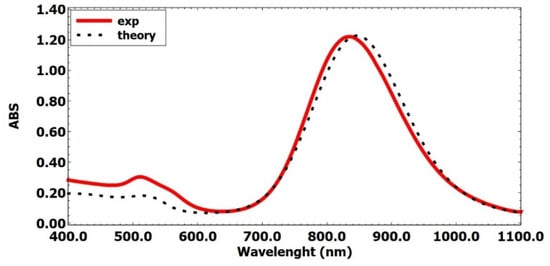
Figure 4.
Diagram of absorbance (ABS) over incident wavelength—experimental and theoretical results.
Figure 4 was considered in an earlier work by Radomski et al. [49], where the same AuNRs were used, but in the present work they were placed at the bottom of a cell. Experimental spectroscopy results (Thermo Fisher Scientific Evolution 220 spectrophotometer, Waltham, MA, USA [49]) are calibrated with the theoretical model for a water-filled cuvette (Figure 4). Both the experimental spectrum and the numerical model show two absorbance peaks appearing at ~520 nm and ~835 nm. It should be noted that the second one has a much higher energy conversion level. The model’s significant agreement with the absorption spectrum measurements makes it possible to perform calculations for almost the entire visible region and part of the infrared region, down to a wavelength of 1100 nm.
In addition, the macroscale CFD model has been tested in various heat transfer systems [1,2,25,29,48,49], demonstrating satisfactory consistency with experimental observations. This further confirms its validity and suitability as a predictive tool for evaluating energy conversion efficiency and temperature distribution over time in both heating and cooling stage. However, in order to fully validate the model, an experiment was prepared on a 3D cylindrical geometry made of PEGT material [50]. Each heat source was designed to study the effect of geometry on the heat distribution within the chamber. To enhance the thermal properties and observe the photothermal effects, both heat sources were coated with a solution of AuNRs by placing one layer of nanoparticles with a concentration of 2.32 mg/mL. These AuNRs used for the experiment are characterized by the following dimensions: (65.0 ± 9.0) × (16.0 ± 3.0) nm with a capping agent shell of CTAB type. Furthermore, the chamber was filled with 2 mL of water for every case. The fiber tip of the used lasers was set to cover the entire area of the selected platform by its beam, as depicted in Figure 5. During the experiments, the temperature distribution on the front wall of the chamber was first measured using an InfiRay T600 thermal imaging camera (resolution 640 × 512 pixels, field of view 24° × 18°, accuracy 35 mK; the emissivity was calibrated for PETG at 0.92; the environmental emissivity was set at 0.95) that was used to calibrate the temperature field in the numerical model. The initial process temperature was 22.8 °C. The experiment used an 808 nm laser with power of 0.8 W for 90 min to obtain steady conditions.
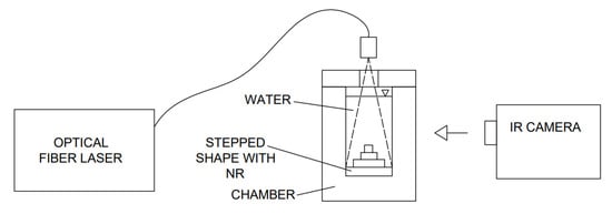
Figure 5.
Diagram of the experimental stand used to determine the temperature of the system.
The experimental results were obtained using an InfiRay T600 thermal imaging camera, and the steady-state temperature contours are shown in Figure 6. In order to thoroughly examine the range of variability on the surface of the chambers, reading lines were selected from the bottom of the chamber to its top at a height of 55.8 mm (white lines in the center of the chamber). The temperature values are shown in Figure 7. A characteristic peak with a higher temperature in the heat source area and a relatively linear decrease towards the top and bottom of the chamber can be seen. For both configurations (C1 and C2), they are similar, but slightly higher values are obtained outside the chamber in the case of configuration C1, which may indicate greater heat loss to the environment.
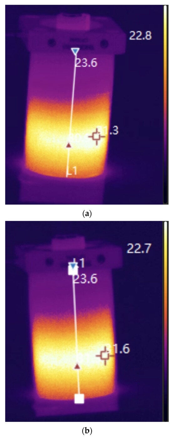
Figure 6.
Experimental results: (a) gradually ascending stepped heat source case (C1); (b) gradually descending stepped heat source case (C2).
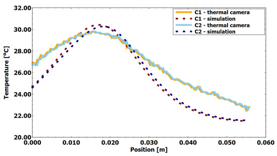
Figure 7.
Comparison of experiment results with the model (X-axis representing the distance from the bottom to the top of the chamber at the outside of it).
2.7. Definition of Nusselt Number and Conditions of CFD Simulation
The CFD simulations were performed using ANSYS Fluent 2025 R2 [46], employing the Expression functionality to model the heat generation rate from the AuNRs (Equation (2)). The simulations were conducted to predict temperature distributions and flow patterns within the chamber, with particular emphasis on the influence of material properties and geometrical configurations on the resulting temperature contours.
The maximum heat generation rate was calculated following the methodology reported by Radomski et al. In addition, the beam intensity distribution and the corresponding heat generation rate for the 15/65 nm AuNRs are presented in Figure 8. The laser beam was assumed to be collimated, with a diameter of 10 mm and a Gaussian intensity distribution.
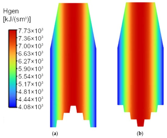
Figure 8.
Beam distribution for 16/65 nm and its corresponding heat generation rate (Named Expression Hgen) for C1 (a) and C2 (b).
Representing the heat source directly as a volumetric heat generation term within a thin nanoparticle layer would require additional assumptions regarding the effective layer thickness (23 nm), nanoparticle concentration (Table 3), and thermophysical properties of gold (Table 2). For each face of the wall zone representing the AuNR-coated surface, the heat generation rate was evaluated using the functions defined by Equations (1)–(6) and assigned via the Named Expression Hgen.
The generated energy within the nanoparticle layer of 23 nm thickness was subsequently transferred to the red surfaces shown in Figure 1 and Figure 2 and imposed as a surface heat flux boundary condition at the solid–fluid interface. In this manner, the volumetric heat generation associated with the AuNRs was consistently converted into an equivalent interfacial heat flux. The Gaussian heat source distribution (Figure 8) was then applied to the wall heat flux boundary condition in Fluent, while the water and air domains were solved assuming zero volumetric heat generation.
During the simulations, the SIMPLE algorithm was employed with the following numerical schemes: pressure discretization using the Body-Weighted scheme and second-order upwind schemes for the momentum and energy equations. The pseudo-transient option was disabled and default under-relaxation parameters were applied.
The mixture multiphase formulation in ANSYS Fluent was used to model air–water mixture. As the flow is buoyancy-driven and the interface is quiescent, homogeneous assumption (zero drift velocity) was adopted so that both phases could share a single velocity field. Gravity was enabled. A 2D unstructured mesh was employed for all simulations. Near-wall inflation layers were used to describe wall layer phenomena in boundary fluid–solid interphase (Figure 9).
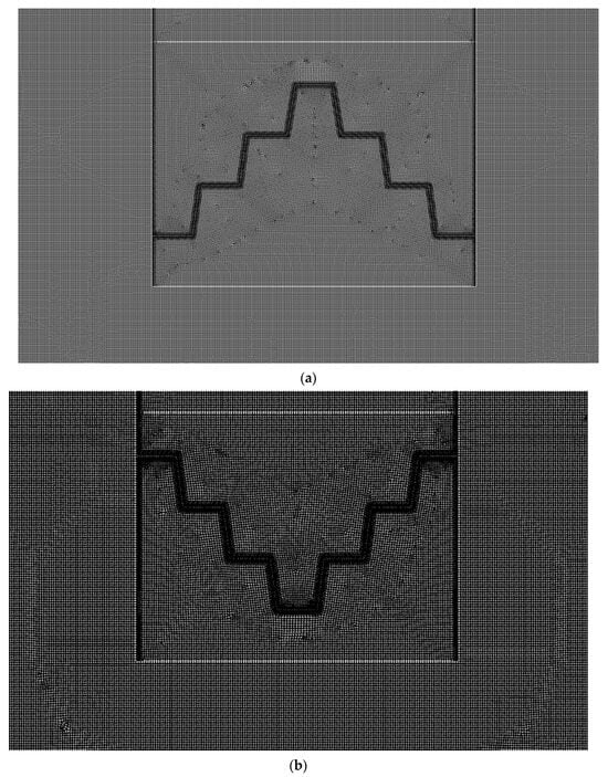
Figure 9.
Discretization of the computational space, namely: (a) in gradually ascending stepped structure with highlighted area of the base and water; (b) in gradually descending stepped structure with highlighted area of the base and water.
The calculation region adjacent to the heated bottom was chosen based on a three-level grid-independence study (coarse/medium/fine). Grid independence was verified by comparing the velocity and temperature in calculation domains, with a change of less than 1% between the medium and fine meshes (Table 4), indicating that the mesh is sufficiently fine to resolve the relevant thermal and momentum (velocity) gradients. Nevertheless, the local Nusselt number along the heated bottom is defined by [51,52]:
where —interface heat flux into water obtained from Fluent [Wm−2], —characteristic length [m], —water thermal conductivity [Wm−1K−1], —local wall temperature at the water [K], and is the bulk water reference temperature [K] (computed as the volume-averaged water temperature in the chamber at steady state). A mesh convergence analysis was performed, taking into account variations in the maximum temperature, the mean water temperature, the maximum velocity in the water region, and an error analysis between meshes for the average water velocity. Table 4 presents details of grid independent test.
Table 4.
Details of grid independent test.
Figure 9a,b show discretization of the computational space in gradually ascending and descending stepped structure, respectively. The computational space was discretized using a tetragonal grid. Fine grids were used for the calculations, with a total of 319,242 cells for the geometry with gradually ascending stepped structure (Figure 9) and 375,356 cells for the geometry with gradually descending stepped structure.
A detailed analysis of the discretization grid was performed, where, in addition to error analysis, the continuity of velocity contours (Figure 10) and temperature contours (Figure 11) was confirmed. The results of numerical studies confirmed that the prepared grid can reproduce significant temperature and velocity gradients occurring in the solved problem with a local heat source on the AuNRs’ surface.
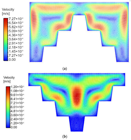
Figure 10.
Velocities’ distribution in the mesh, namely: in gradually ascending stepped structure with highlighted area of the water (a), and in gradually descending stepped structure with highlighted area of the water (b).
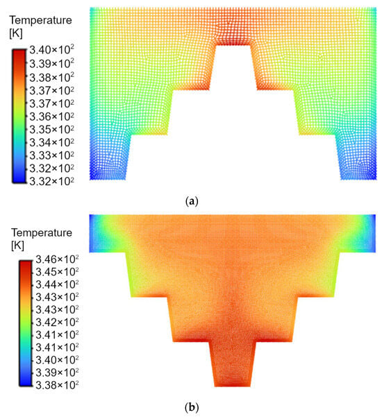
Figure 11.
Temperature distribution in the mesh, namely: in gradually ascending stepped structure with highlighted area of the base and water (a), and in gradually descending stepped structure with highlighted area of the base and water (b).
All grid analyses were performed for nanoparticles with dimensions as in the calibration experiment, i.e., for AuNRs 16/65. Furthermore, as part of the correction related to the transition from the 3D experiment to 2D calculations, it was necessary to adopt a coefficient related to the change in the field to which heat is supplied and the field from which heat is received. It was calculated that for the axisymmetric geometry of the cylinder used in the experiment and the 2D geometry used, the ratio is 3.61765. Therefore, a coefficient of = 1/3.61765 was adopted for the calculations. The two-dimensional numerical model was validated based on experimental results and demonstrated satisfactory agreement, justifying its use for further design analyses. The numerical results exhibit qualitative agreement with the experimental observations and are primarily intended to support the preliminary selection of materials and geometrical configurations for the bactericidal chamber. At this stage, the objective of the numerical analysis is to identify trends and provide design guidelines rather than to achieve exact quantitative agreement.
3. Results and Discussion
3.1. Temperature Contours
The CFD results for the temperature distribution in the chamber are presented in Figure 12 and Figure 13. Figure 12 compares the temperature contours for various AuNRs’ aspect ratios and the two heat source configurations (C1: with a gradually ascending stepped structure and C2: with a gradually descending stepped structure) using PETG as the construction materials for the base and insulation.
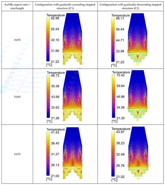
Figure 12.
Temperature contours with velocity vectors using various AuNRs’ aspect ratios, in the case of PETG material construction.
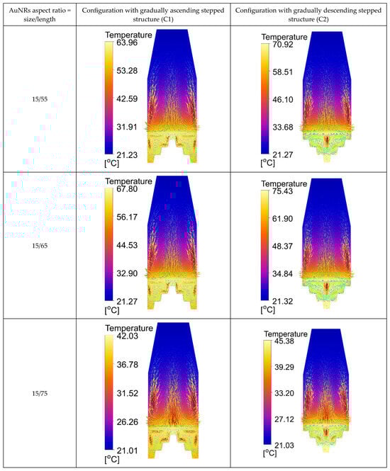
Figure 13.
Temperature contours with velocity vectors using various AuNRs’ aspect ratio, in the case of PDMS material construction.
PETG Construction (Figure 12): The results indicate that the C2 configuration leads to higher maximum temperatures and more uniform heat distribution compared to the C1 configuration. This is crucial for ensuring effective bacterial inactivation, as the higher and more uniform distributed temperatures improve the probability of achieving the required thermal conditions across the entire device.
Figure 13 presents the results for the chamber where PETG is used as the insulation material and the base is made of PDMS. Similarly, the C2 configuration with a PDMS base also shows higher maximum and mean temperatures compared to the C1 case. However, the temperature gradients are slightly less uniform than those observed with PETG, which could impact the effectiveness of bacterial inactivation.
Additionally, the results presented in Table 5 and Table 6 show that the C2 configuration (with a gradually descending stepped structure) consistently achieves higher maximum, minimum, and mean temperatures compared to the C1 configuration (with a gradually ascending stepped structure) for both PETG and PDMS constructions of the base. In the PETG case (Table 5), the C2 configuration reaches maximum temperatures of up to = 72.42 °C, with a more uniform mean temperature distribution, indicating better heat storage and distribution, which is critical for effective bacterial inactivation. In contrast, the C1 configuration shows lower temperature values, with maximum temperatures ranging between = 41.53 °C (aspect ratio 15/75) and 66.73 °C (aspect ratio 15/65), depending on the shape of the AuNRs. Furthermore, in the PDMS base case (Table 6), the C2 configuration again results in higher maximum temperatures, reaching up to = 75.45 °C, with a more consistent mean temperature compared to the C1 configuration, which shows lower maximum temperatures around = 67.88 °C. These findings suggest that the C2 configuration, particularly when using the PDMS base, offers a superior performance by achieving the necessary thermal conditions for effective bacterial inactivation. The higher temperatures observed in the C2 configuration across both materials highlight its effectiveness in retaining and distributing heat, making it the preferable choice for applications requiring sustained high temperatures. Similarly, the highest temperature increase is observed for the 15–65 nm AuNRs upon laser irradiation, which can be attributed to the reaching of plasmon resonance.
Table 5.
Results of maximum, minimum, and mean temperature values of the water in °C using various AuNRs’ aspect ratios and both configurations of heat source, in the case of PETG base material.
Table 6.
Results of maximum, minimum, and mean temperature values of the water in °C using various AuNRs’ aspect ratios and both configurations of heat source, in the case of PDMS as base material.
3.2. Nusselt Number
Figure 14, Figure 15 and Figure 16 show the local Nusselt number of the heat source for the different cases analyzed. The Nusselt number provides information on the efficiency of the convective heat transfer at the bottom surface covered with AuNR. The X-axis represents the distance along the bottom of the chamber where the AuNRs are deposited (cf. Figure 2 and Figure 3).
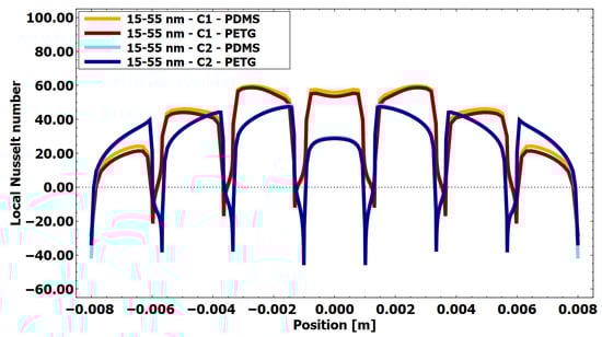
Figure 14.
Local Nusselt number at the heat source for an aspect ratio of 15/55 for AuNRs, using PETG insulation and PETG and PDMS as the base (X-axis representing the distance along the base of the chamber with deposited AuNRs).
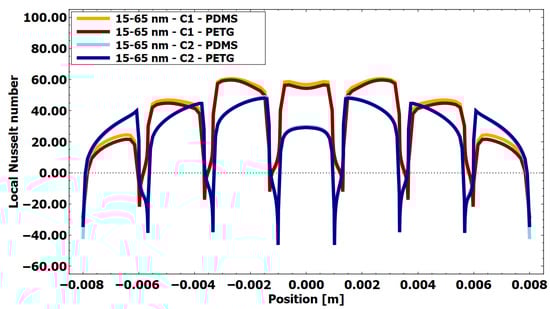
Figure 15.
Local Nusselt number at the heat source for an aspect ratio of 15/65 for AuNRs, using PETG insulation and PETG and PDMS as the base (X-axis representing the distance along the base of the chamber with deposited AuNRs).
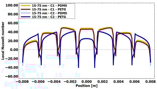
Figure 16.
Local Nusselt number at the heat source for an aspect ratio of 15/57 for AuNRs, using PETG insulation and PETG and PDMS as the base (X-axis representing the distance along the base of the chamber with deposited AuNRs).
Figure 14 shows the spatial evolution of the local Nusselt number for AuNRs with an aspect ratio of 15/55 nm. A periodic variation is observed for all configurations, reflecting the stepped geometry of the heat source. Local maxima appear near the edges of the steps, where flow acceleration and boundary layer disruption enhance the convective heat transfer, while minima correspond to recessed areas characterized by weaker convection. Configuration C1 (a gradually ascending stepped surface) consistently exhibits higher Nusselt numbers for both PETG and PDMS substrates, indicating the more efficient convective dissipation of heat from the heat source. In contrast, configuration C2 exhibits lower Nusselt numbers, suggesting weaker convection and increased thermal boundary layer development. Despite reduced convective efficiency, the lower Nusselt numbers in C2 are associated with higher fluid temperatures, which are more favorable for bacterial inactivation.
Figure 15 illustrates the local distribution of the Nusselt number for AuNRs with an aspect ratio of 15/65 nm. Compared to the 15/55 nm case, there is a slight increase in the amplitude of the Nusselt number, reflecting the greater heat production associated with the increase in the length of the nanorods. Nevertheless, the qualitative spatial evolution remains unchanged, confirming that the convective heat transfer model is primarily governed by the geometry of the lower surface. As in Figure 14, configuration C1 produces higher local Nusselt numbers due to the intensification of convection near the ascending steps, while configuration C2 favors heat retention in the fluid domain. This demonstrates that an increase in heat production does not necessarily lead to higher convective efficiency.
Figure 16 shows the local evolution of the Nusselt number for the largest aspect ratio AuNR (15/75 nm). The same oscillatory behavior is observed, with pronounced peaks at the edges of the steps and reduced values in the recessed areas. The increase in the heat source intensity results in slightly higher maximum Nusselt numbers, while the relative differences between configurations remain constant. Geometry C1 continues to exhibit superior convective efficiency, while geometry C2 shows lower Nusselt numbers over most of the surface. Furthermore, in configuration C2, the reduced fluid motion occurs in a favorable location (cf. Figure 10b and Figure 12, and Figure 13), as it promotes thermal energy storage in this region and results in a significant temperature increase compared to configuration C1. Consequently, the Nusselt number for this configuration is presented primarily as an illustrative metric, reflecting the local heat transfer characteristics rather than serving as a direct indicator of the overall thermal performance.
In all cases analyzed, the PETG and PDMS base materials give very similar local and average Nusselt numbers. The slight difference in thermal conductivity (0.15 vs. 0.11 W·m−1K−1) results in only a marginal variation in the overall thermal resistance of the wall, which has a limited influence on the convective heat transfer at the fluid–solid interface. Therefore, the Nusselt number is mainly determined by the internal convection patterns imposed by the geometry of the lower surface (C1 vs. C2), rather than by the base material. This observation is consistent with the similar mean water temperatures shown in Table 4 and Table 5. Comparable ranges of Nusselt numbers have been reported in the literature [53,54,55] for different heating mechanisms, indicating that similar convective regimes can be achieved. The present results further confirm the effectiveness of gold nanorods as localized heat sources capable of maintaining an efficient thermal performance.
Overall, the evolution of the Nusselt number across all figures demonstrates that the bottom surface geometry has a stronger influence on the convective heat transfer than the AuNR base material, reinforcing the importance of a geometric assessment in the design of bactericidal chambers.
3.3. Plasmon Resonance Peak
Figure 17 presents the theoretical UV-Vis absorption spectra of AuNRs with transverse and longitudinal plasmon resonance peaks corresponding to the dimensions considered in this study, dispersed in a water medium. As may be noticed, the transverse resonance peak appears at approximately 520 nm, which is consistent with values reported in the literature for AuNPs. In contrast, the position of the longitudinal plasmon peak mainly depends on the aspect ratio, defined as the ratio of the length to the nanorod diameter. In the present study, AuNRs with dimensions of () 15–55, 15–65, and 15–75 nm exhibit the longitudinal peak position at 771, 809, and 871 nm, respectively.
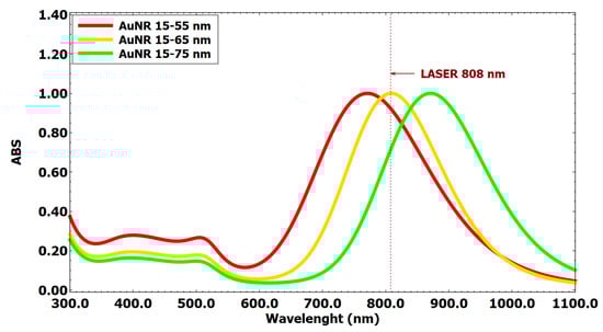
Figure 17.
Theoretical absorption spectra of AuNRs of a size of 15 nm and length (red line) 55, (yellow) 65, and (green) 75 nm, according to the discussed model.
The observed tendency towards a higher temperature increase can be attributed to the matching of the laser wavelength with the plasmon resonance peak, as presented in Figure 17. Notably, 15–65 nm AuNRs exhibit a resonance peak that closely matches with the excitation wavelength (laser 808 nm), leading to the highest absorbance value. This enhanced optical absorption results in a more efficient energy conversion process and, consequently, greater heat dissipation. It should be noted that this dependence is not expected to be linear, owing to the logarithmic scale commonly applied in UV-Vis spectroscopic analysis.
3.4. Entropy Contours
The energy dissipation process can be analyzed through the entropy contours presented in Figure 18 and Figure 19. In general, entropy contours qualitatively resemble temperature distributions, while discontinuities are observed only at the air–water interface due to changes in material properties. Entropy generation in this context reflects irreversible heat transfer and viscous dissipation within the system, rather than a direct measure of performance or efficiency. The results indicate a broader spatial distribution of entropy generation in the configuration with a gradually descending stepped structure. From a classical thermodynamic perspective, increased entropy generation signifies enhanced irreversibility and intensified energy dissipation within the fluid. Such behavior is typically minimized in systems designed for mechanical or thermal efficiency, as discussed by Feidt et al. [56], Bejan [57], and in optimization studies of turbine stages and heat exchangers [58,59,60].
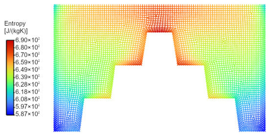
Figure 18.
Entropy contours for the configuration with a gradually ascending stepped structure, using AuNRs with an aspect ratio of 15/65 and a PETG base.
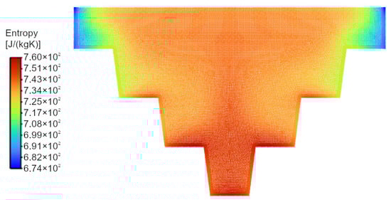
Figure 19.
Entropy contours for the configuration with a gradually descending stepped structure, using AuNRs with an aspect ratio of 15/65 and a PETG base.
However, in one-way multiphysical and multiscale systems, entropy generation does not necessarily correspond to a detrimental system outcome. In the present configuration, the increased entropy generation is associated with stronger interactions between AuNRs and the surrounding fluid, leading to elevated local temperatures and the enhanced internal energy of the fluid. This interpretation is consistent with studies addressing entropy production in terms of irreversible interactions and deviations from thermodynamic equilibrium [61,62,63], as well as the Gyftopoulos–Beretta formulation of thermodynamics, where entropy generation accompanies irreversible processes within interacting systems [64,65,66].
Consequently, the larger regions of elevated entropy observed in Figure 19 indicate intensified irreversible energy dissipation arising from nanoparticle–fluid interactions. While this implies higher thermodynamic irreversibility, it also corresponds to increased thermal energy deposition in the fluid, which is relevant for applications such as localized heating and potential bacterial inactivation.
Furthermore, from the perspective of nonequilibrium thermodynamics, particularly the Onsager theory of irreversible processes, entropy production arises from the coupling between thermodynamic fluxes and forces. In this formulation, entropy generation is expressed as a bilinear form of generalized fluxes (e.g., heat flux and momentum flux) and their corresponding thermodynamic forces (e.g., temperature gradients and velocity gradients). Consequently, enhanced entropy generation reflects intensified transport processes and stronger coupling between thermal and hydrodynamic fields [67].
The configuration with a gradually descending stepped structure exhibits a broader spatial distribution of entropy generation. According to the Onsager framework, this behavior indicates increased irreversible transport driven by stronger gradients and enhanced nanoparticle–fluid interactions. While such conditions lead to higher entropy production—typically undesirable in systems optimized for thermodynamic efficiency—they are a direct consequence of intensified irreversible heat and momentum exchange.
3.5. Discussion
The velocity contour results shown in Figure 10a and the velocity vectors presented in Figure 12 and Figure 13 for the gradually ascending stepped structure (C1), with the water region highlighted, indicate the formation of two nearly independent upward flow streams on both sides of the base, with characteristic velocities at the order of 0.7 mm/s. Starting from the lowest step of the base, the fluid is progressively heated as it ascends along successive steps, where an increasing fraction of electromagnetic energy is converted into heat, consistent with the heat generation rate distribution ( shown in Figure 8. The fluid heated near the top of the AuNRs-coated base spreads laterally in two directions and merges with the ascending flow structures. Subsequently, the heated water streams reach the free water surface, where they spread in opposite directions. Part of the thermal energy is transferred to the air, after which two vortical structures are formed, both rotating from the heat source region toward the insulated side walls. These vortex structures, interacting with the chamber geometry, induce specific mechanisms of heat accumulation and heat release. In particular, stagnation regions form in the lowest part of the base coated with AuNRs. Due to the Gaussian distribution of , heat generation in this peripheral region is relatively low, and the lack of fluid motion results in the persistence of comparatively lower temperatures than in the rest of the water volume. In configuration C1, higher temperatures are maintained primarily within the vortical structures (cf. Figure 10 and Figure 11); however, due to the fluid motion, the generated heat flux is efficiently transported toward the insulated walls. This intensified heat transfer is evident in both experimental and numerical results (Figure 7), as the walls in configuration C1 reach higher temperatures than those in configuration C2. Elevated external wall temperatures promote an increased heat exchange with the surroundings, leading to higher heat losses and a lower level of stored thermal energy.
A markedly different behavior is observed in configuration C2, where the chamber geometry and the resulting convective flow patterns favor both convection and thermal energy storage. While these two mechanisms often compete in many systems, in the proposed configuration they can act synergistically. The primary factor enabling this behavior is that the beam distribution and the corresponding heat generation rate are concentrated in a region of the chamber characterized by the widest insulation thickness, thereby reducing direct heat losses from the electromagnetic-to-thermal energy conversion zone. Moreover, in the region of the maximum for configuration C2, the fluid motion is practically negligible (Figure 10b, Figure 12 and Figure 13), making this area locally optimal for thermal energy storage. As a result, a region of an elevated temperature develops (Figure 12 reaching up to 72.4 °C and Figure 13 exceeding 75 °C), yielding maximum temperatures which are several degrees higher in all C2 configurations compared to C1. This localized high-temperature region subsequently intensifies natural convection, manifested by nearly twice the upward flow velocity relative to C1, with the ascending current reaching approximately 1.2 mm/s.
The convective structure reaches the free water surface and spreads across the entire width toward the insulated walls. However, in contrast to configuration C1, the insulation walls in C2 are lower, allowing the cooled descending flow to interact with successive descending steps, thereby partially regenerating the temperature. These descending convective structures propagate significantly more slowly than the ascending ones, which enhances fluid mixing. This effect is confirmed by the data presented in Table 5 and Table 6, where configuration C2 exhibits smaller differences between maximum and minimum temperatures than configuration C1. Furthermore, the increased insulation width is beneficial for thermal energy accumulation, ultimately leading to higher average temperatures in configuration C2 compared to C1.
Furthermore, it should be emphasized that the thermal energy storage capacities of both configurations are comparable. This follows from the fact that the volumes of the individual structural elements are analogous and that the product of the density and specific heat capacity is of a similar magnitude for both materials. Although PDMS exhibits a higher specific heat capacity (1460 J·kg−1·K−1) than PETG (1200 J·kg−1·K−1), its lower density offsets this advantage, resulting in an overall difference in the thermal storage capacity of only 7.6% in favor of PETG. Consequently, material-related differences in the heat capacity do not dominate the observed thermal behavior, and the results are primarily governed by the chamber geometry and the associated convective heat transfer mechanisms.
The simulation results provide clear illustrations of the impact of different configurations and materials on the temperature contours, mean temperature values, and Nusselt number and, in the further perspective, also the efficiency of bacterial inactivation in microfluidic devices. Although the C1 configuration, with its gradually ascending stepped structure, has a higher Nusselt number, indicating a more efficient convective heat transfer, this does not necessarily translate into a better performance for this specific application. Convective heat transfer is important in many contexts, but for bacterial inactivation, the ability to retain heat and maintain high temperatures over time is crucial. Configuration C2, featuring the gradually descending stepped structure, offers a better performance than C1 in this respect. Configuration C2 consistently achieves higher maximum temperatures, which is essential to ensure that bacteria are exposed to lethal temperatures throughout the device. This is particularly important in these scenarios where a uniform heat distribution can significantly increase the probability of effective bacterial inactivation.
C2 achieves higher steady-state temperatures and lower convective losses (lower local Nusselt number Nu) than C1, consistent with improved thermal retention at a steady state. The assessment of how long these temperatures persist requires transient analysis and will be addressed in future work. These results highlight the importance of considering both the geometric configuration of the heat source and the material properties when designing the germicidal chamber for bacterial inactivation. The C2 configuration, particularly when combined with PDMS, offers a more efficient solution, ensuring that the necessary thermal conditions are consistently met throughout the device, leading to more effective bacterial inactivation results. This comprehensive approach to design—which takes account of both the physical structure and material characteristics—ensures that the device operates effectively under real-life conditions.
Moreover, when analyzing different ratios of AuNRs dimensions, it is found that there is no linear relationship between the change in the AuNR length and the temperature rise reached. It is expected to be due to the logarithmic scale commonly applied in UV-Vis spectroscopic analysis. The highest values are obtained for the intermediate ratio, namely with a length of 65 nm and a diameter of 15 nm.
Looking at the mean temperature in the entire chamber, it has been discovered that laser-irradiated AuNRs appear to be a promising solution as a substitute for water contamination processes. Comparing with the literature, gold nanoparticles are recognized to be useful due to their potential in heating processes [68]. Moreover, the input energy required to decontaminate water from bacteria requires hundreds, if not thousands, of watts, whereas in the case of light-illuminated gold nanoparticles, a lamp with a power density of approximately 10 W/cm2 is sufficient, as declared in the [69] publication. This was also experimentally confirmed in the authors’ work [70], where gold nanorods were irradiated with a 14.7 W/cm2 yellow lamp.
Although the geometry of the gold nanostructures was already optimized in [15], the shape optimization is still unexplored, and the investigated chamber is one of the geometries that can be used for the effective process of bacteria inactivation.
The confirmation of this relationship applies to different insulator materials and different heat source shapes. Increasing the length from 55 nm to 65 nm turns out to be advantageous, but the further expansion of this parameter to 75 nm already causes a significant decrease in the attainable temperature, as it is 15 K lower than the initial version.
The results presented in this study are based on steady-state simulations, which represent the asymptotic thermal and flow conditions reached after a sufficiently long heating period. While this approach allows for a clear comparison of different chamber geometries and material configurations, it does not explicitly capture the transient heating phase.
In practical applications, the time required to reach the reported temperature levels may influence the effectiveness of bacterial inactivation, as microbial reduction depends on both the temperature and exposure duration. Transient thermal effects may, therefore, play a role during the initial heating stage, particularly in determining the time needed to achieve critical temperatures throughout the fluid domain.
Nevertheless, the steady-state analysis provides valuable insight into the ultimate thermal performance of the system, the spatial distribution of high-temperature regions, and the long-term balance between heat generation, convection, and losses. These factors are essential for identifying favorable design trends and for assessing the maximum achievable thermal conditions within the chamber.
A detailed transient analysis, including the heating-up time and time-dependent bacterial inactivation metrics, is planned as part of future work once a near-optimal chamber configuration has been identified.
4. Conclusions and Future Perspectives
The simulations show that the geometric configuration and material choice affect the temperature distribution and bacterial inactivation efficiency. Although C1 exhibits higher Nusselt numbers, C2 reaches higher and more uniform temperatures, making it more suitable for sustained thermal disinfection. This effect is enhanced when combined with PETG due to better thermal retention. Transient effects require further study.
Tests with AuNRs reveal no linear correlation between the nanorod length and temperature increase, with optimal heating at 65 nm × 15 nm dimensions. Laser-irradiated AuNRs offer a promising, energy-efficient alternative to conventional thermal water treatment, requiring significantly lower power densities. Increasing the nanorod length beyond 65 nm reduces the achievable temperature by approximately 15 K.
In one-way multiphysical and multiscale systems, the classical Clausius-based interpretation of entropy, while fundamental, is not always sufficient to fully characterize the performance of processes operating far from thermodynamic equilibrium. Entropy generation remains a rigorous measure of irreversibility and energy dissipation; however, its interpretation must be considered in the context of coupled transport phenomena and scale interactions. Within the framework of nonequilibrium thermodynamics and the Onsager reciprocal relations, entropy production arises from the interaction of thermodynamic fluxes and their conjugate driving forces, such as temperature gradients and the buoyancy-induced flow.
In the present system, the configuration with a gradually descending stepped structure promotes stronger coupling between nanoparticle-induced heat generation and natural convection in the surrounding fluid. This enhanced coupling increases the internal energy of the fluid and leads to higher characteristic temperature levels within the chamber. The larger spatial extent of regions with elevated entropy generation reflects intensified irreversible heat and momentum transport associated with this coupling. From an engineering perspective, this behavior indicates the more effective utilization of the supplied energy for heating the fluid volume, which is directly relevant to achieving the thermal conditions required for bacterial inactivation.
Owing to the widespread availability of various light sources on the market and the close correspondence between the laser wavelength and the resonance peak of selected AuNRs, it was possible to achieve a high temperature increase. Future work assumes that gold nanorods will be optimized for specific wavelengths so that the highest absorption achieved on a nanoscale corresponds to laser light excitation on a microscale, resulting in the most efficient outcome on a macroscale.
Another promising direction involves the development of a full 3D multiphysics model that captures both nanoscale, microscale, and macroscale phenomena, including nanoparticle agglomeration and melting effects when laser power thresholds are exceeded. However, such modeling would substantially increase the computational cost and preparation effort, making it more suitable for verification rather than early-stage design.
While the present study focuses on two fixed-stepped geometries (C1 and C2), the results suggest that further optimization within the C2 configuration is possible through the systematic variation of key geometric parameters. In particular, the step height, step pitch, and the width of the lower saucer region are expected to strongly influence the balance between localized thermal storage near the AuNR-coated surface and buoyancy-driven convection. A dedicated sensitivity analysis of these parameters would provide quantitative guidelines for optimizing the stepped geometry and is identified as a natural direction for future work.
Author Contributions
Conceptualization, P.Z.; methodology, P.Z., P.R. and A.K.; software, P.R. and A.K.; validation, P.Z. and A.K.; formal analysis, A.K. and J.B.; investigation, D.K. and P.R.; resources, P.Z. and P.R.; data curation, A.K. and P.R.; writing—original draft preparation, P.Z. and A.K.; writing—review and editing, P.R., D.K., J.B. and D.M.; visualization, P.Z., A.K. and D.K.; supervision, D.M.; project administration, P.Z.; funding acquisition, P.Z. All authors have read and agreed to the published version of the manuscript.
Funding
This research was funded by National Science Center in Poland under research project Shape and displacement optimization of gold nanorods in the killing chamber in order to photothermoablation processes, no. UMO 2021/43/D/ST8/02504.
Data Availability Statement
The raw data supporting the conclusions of this article will be made available by the authors on request.
Acknowledgments
This research was undertaken with the assistance of resources from the National Science Center in Poland.
Conflicts of Interest
The authors declare no conflicts of interest.
References
- Ziółkowski, P.; Koulali, A.; Radomski, P.; De Biase, D.; Zaccagnini, F.; Zielinski, J.; Pikuła, M.; Jeong, K.; Petronella, F.; De Sio, L.; et al. Bacterial inactivation via laser-driven gold nanoparticle heating: Simulation and analysis. In Proceedings of the 9th Thermal and Fluids Engineering Conference (TFEC), Corvallis, OR, USA, 21–24 April 2024; Begel House Inc.: Danbury, CT, USA, 2024; pp. 715–726. [Google Scholar] [CrossRef]
- Koulali, A.; Ziółkowski, P.; Radomski, P.; Petronella, F.; Zaccagnini, F.; Szczecińska, W.; De Biase, D.; Butt, U.A.; Zieliński, J.; De Sio, L.; et al. Enhancing Bacteria Inactivation: Computational Insight into The Use of Laser-Irradiated Gold Nanoparticles. In Biotechnology and Human Enhancement: Present Research and Future Perspectives; De Sio, L., Turmus, E.K., Eds.; Springer Nature B.V.: Dordrecht, The Netherlands, 2025; pp. 145–172. [Google Scholar]
- Guglielmelli, A.; Pierini, F.; Tabiryan, N.; Umeton, C.; Bunning, T.J.; De Sio, L. Thermoplasmonics with gold nanoparticles: A new weapon in modern optics and biomedicine. Adv. Photonics Res. 2021, 2, 2000198. [Google Scholar] [CrossRef]
- Sforza, M.L.; Petronella, F.; De Biase, D.; Zaccagnini, F.; Lim, S.; Butt, U.A.; D’Alessandro, A.; Godman, N.P.; Evans, D.R.; McConney, M.; et al. Cascade structured plasmonic liquid crystal biosensor for the rapid detection of harmful bacteria dispersed in potable water. Adv. Sens. Res. 2024, 3, 2300201. [Google Scholar] [CrossRef]
- Wylie, M.P.; Craig, R.A.; Gorman, S.P.; McCoy, C.P. Development of a high-level light-activated disinfectant for hard surfaces and medical devices. Int. J. Antimicrob. Agents 2021, 58, 106360. [Google Scholar] [CrossRef]
- Walker, T.; Canales, M.; Noimark, S.; Page, K.; Parkin, I.; Faull, J.; Bhatti, M.; Ciric, L. A Light-Activated Antimicrobial Surface Is Active Against Bacterial, Viral and Fungal Organisms. Sci. Rep. 2017, 7, 15298. [Google Scholar] [CrossRef] [PubMed]
- Kang, Y.; Kato, S. Thermal and non-thermal germicidal effects of microwave radiation on microbial agents. Indoor Built Environ. 2014, 23, 1080–1091. [Google Scholar] [CrossRef]
- Nagy, D.; Zsom, T.; Taczman Brückner, A.; Somogyi, T.; Zsom Muha, V.; Felföldi, J. Comparison of the Bactericidal Effect of Ultrasonic and Heat Combined with Ultrasonic Treatments on Egg Liquids and Additional Analysis of Their Effect by NIR Spectral Analysis. Sensors 2024, 24, 4547. [Google Scholar] [CrossRef]
- Petronella, F.; De Biase, D.; Zaccagnini, F.; Verrina, V.; Lim, S.; Jeong, K.; Miglietta, S.; Petrozza, V.; Scognamiglio, V.; Godman, N.P.; et al. Label-free and reusable antibody-functionalized gold nanorod arrays for the rapid detection of Escherichia coli cells in a water dispersion. Environ. Sci. Nano 2022, 9, 3343–3360. [Google Scholar] [CrossRef]
- Méndez-Pfeiffer, P.A.; Soto Urzúa, L.; Sánchez-Mora, E.; González, A.L.; Romo-Herrera, J.M.; Arciniega, J.J.G.; Morales, L.J.M. Damage on Escherichia coli and Staphylococcus aureus using white light photoactivation of Au and Ag nanoparticles. J. Appl. Phys. 2019, 125, 213102. [Google Scholar] [CrossRef]
- Déjardin, J.-L.; Kachkachi, H. Heat Generation and Diffusion in an Assembly of Magnetic Nanoparticles: Application to Magnetic Hyperthermia. Appl. Sci. 2024, 14, 5757. [Google Scholar] [CrossRef]
- Balois, M.V.; Hayazawa, N.; Catalan, F.C.; Kawata, S.; Yano, T.A.; Hayashi, T. Tip-enhanced THz Raman spectroscopy for local temperature determination at the nanoscale. Anal. Bioanal. Chem. 2015, 407, 8205–8213. [Google Scholar] [CrossRef] [PubMed]
- Loeb, S.; Chuanhao, L.; Jae-Hong, K. Solar photothermal disinfection using broadband-light absorbing gold nanoparticles and carbon black. Environ. Sci. Technol. 2018, 52, 205–213. [Google Scholar] [CrossRef]
- Nevárez Martínez, M.C.; Kreft, D.; Grzegorczyk, M.; Mahlik, S.; Narajczyk, M.; Zaleska-Medyńska, A.; Morales, D.P.; Hollingsworth, J.A.; Werner, J.H. Numerical Simulation of Light to Heat Conversion by Plasmonic Nanoheaters. Nano Lett. 2025, 25, 230–235. [Google Scholar] [CrossRef] [PubMed]
- Koulali, A.; Radomski, P.; Ziółkowski, P.; Petronella, F.; De Sio, L.; Mikielewicz, D. Differential evolution-optimized gold nanorods for enhanced photothermal conversion. Sci. Rep. 2025, 15, 9543. [Google Scholar] [CrossRef]
- Ziółkowski, P.; Koulali, A.; Radomski, P.; Zaccagnini, F.; Mukha, I.; Petronella, F.; De Sio, L.; Mikielewicz, D. Optimization of energy conversion in gold nanoparticles irradiated by light for sustainable energy applications. In Proceedings of the 37th International Conference on Efficiency, Cost, Optimization, Simulation and Environmental Impact of Energy Systems, ECOS 2024, Rhodes, Greece, 5–30 July 2024; Curran Associates, Inc.: Red Hook, NY, USA, 2024; Volume 1, pp. 617–628. [Google Scholar] [CrossRef]
- Pavlenko, A. Analysis of Methods for Intensifying Heat and Mass Transfer in Liquid Media. Energies 2025, 18, 1419. [Google Scholar] [CrossRef]
- Habib, M.A.; Attya, A.M.; Said, S.A.M.; Eid, A.I.; Aly, A.Z. Heat transfer characteristics and Nusselt number correlation of turbulent pulsating pipe air flows. Heat Mass Transf. 2004, 40, 307–318. [Google Scholar] [CrossRef]
- Hadjiconstantinou, N.G.; Simek, O. Constant-Wall-Temperature Nusselt Number in Micro and Nano-Channels. J. Heat Transf. 2002, 124, 356–364. [Google Scholar] [CrossRef]
- Martínez-Ramos, T.; Corona-Jimenez, E.; Ruiz-Lopez, I.I. Analysis of ultrasound-assisted convective heating/cooling process: Development and application of a Nusselt equation. Ultrason. Sonochem 2021, 74, 105575. [Google Scholar] [CrossRef] [PubMed]
- Karadag, R.; Teke, I. New approach relevant to floor Nusselt number in floor heating system. Energy Convers. Manag. 2007, 49, 1134–1140. [Google Scholar] [CrossRef]
- Benkherbache, S.; Amroune, S.; Belaadi, A.; Zergane, S.; Farsi, C. Numerical Analysis of Natural Convection in an Annular Cavity Filled with Hybrid Nanofluids under Magnetic Field. Energies 2024, 17, 4671. [Google Scholar] [CrossRef]
- Ziółkowski, P.; Radomski, P.; Koulali, A.; Kreft, D.; Mikielewicz, D. CFD Numerical Calculations for Heat Transfer Intensification in a Chamber with Gold Nanorods as an Internal Heat Source. In Proceedings of the Wyzwania w Wymianie Ciepła i Masy, Tom II, XVII Symposium on Heat and Mass Transfer (SWCiM 2025), Kielce, Poland, 8–10 September 2025; pp. 1070–1088. [Google Scholar]
- Alatawi, E.S.; Sannyashi, B.; Nasrin, R.; Ferdoushi, M.Z.; Feng, Z.-G. Efficiency Enhancement of a Cone–Column Combined Microchannel Heat Sink Featuring Graphene–Water Nanofluid. Energies 2025, 18, 1727. [Google Scholar] [CrossRef]
- Zheng, W.; Sun, J.; Ma, C.; Yu, Q.; Zhang, Y.; Niu, T. Numerical Study of Fluid Flow and Heat Transfer Characteristics in a Cone-Column Combined Heat Sink. Energies 2021, 14, 1605. [Google Scholar] [CrossRef]
- Radomski, P.; Ziółkowski, P.; De Sio, L.; Mikielewicz, D. Computational fluid dynamics simulation of heat transfer from densely packed gold nanoparticles to isotropic media. Arch. Thermodyn. 2021, 42, 87–113. [Google Scholar] [CrossRef]
- Khan, U.; Zaib, A.; Waini, I.; Ishak, A.; Sherif, E.-S.M.; Xia, W.-F.; Muhammad, N. Impact of Smoluchowski Temperature and Maxwell Velocity Slip Conditions on Axisymmetric Rotated Flow of Hybrid Nanofluid past a Porous Moving Rotating Disk. Nanomaterials 2022, 12, 276. [Google Scholar] [CrossRef]
- Baldea, I.; Iacoviță, C.; Gurgu, R.A.; Vizitiu, A.S.; Râzniceanu, V.; Mitrea, D.R. Magnetic Hyperthermia with Iron Oxide Nanoparticles: From Toxicity Challenges to Cancer Applications. Nanomaterials 2025, 15, 1519. [Google Scholar] [CrossRef]
- Radomski, P.; Zaccagnini, F.; Ziółkowski, P.; Petronella, F.; De Sio, L.; Koulali, A.; Mikielewicz, D. Investigations of energy conversion and surface effect for laser-illuminated gold nanorod platforms. Energies 2024, 17, 2587. [Google Scholar] [CrossRef]
- Wang, R.; Chai, J.; Luo, B.; Liu, X.; Zhang, J.; Wu, M.; Wei, M.; Ma, Z. A review on slip boundary conditions at the nanoscale: Recent development and applications. Beilstein J. Nanotechnol. 2021, 12, 1237–1251. [Google Scholar] [CrossRef]
- Ziółkowski, P.; Badur, J. A theoretical, numerical and experimental verification of the Reynolds thermal transpiration law. Int. J. Numer. Methods Heat Fluid Flow 2018, 28, 64–80. [Google Scholar] [CrossRef]
- Yan, W.; Ge, W.; Qian, Y.; Lin, S.; Zhou, B.; Liu, W.K.; Lin, F.; Wagner, G.J. Mul-ti-physics modeling of single/multiple-track defect mechanisms in electron beam selective melting. Acta Mater. 2017, 134, 324–333. [Google Scholar] [CrossRef]
- Bayat, M.; Dong, W.; Thorborg, J.; To, A.C.; Hattel, J.H. A review of multi-scale and multi-physics simulations of metal additive manufacturing processes with focus on modeling strategies. Addit. Manuf. 2021, 47, 102278. [Google Scholar] [CrossRef]
- Baetens, D.; Schoofs, K.; Somers, N.; Denys, S. A brief review on Multiphysics modelling of the various physical and chemical phenomena occurring in active pho-tocatalytic oxidation reactors. Curr. Opin. Green Sustain. Chem. 2023, 40, 100764. [Google Scholar] [CrossRef]
- Barchiesi, E. Multi-scale and multi-physics: Towards next-generation engineering materials. Continuum Mech. Thermodyn. 2020, 32, 541–554. [Google Scholar] [CrossRef]
- Geers, M.; Kouznetsova, V.; Brekelmans, W. Multi-scale computational homoge-nization: Trends and challenges. Jnl. Comp. Appl. Math. 2010, 234, 2175–2182. [Google Scholar] [CrossRef]
- Turco, E.; Golaszewski, M.; Giorgio, I.; D’Annibale, F. Pantographic lattices with non-orthogonal fibres: Experiments and their numerical simulations. Compos. B Eng. 2017, 118, 1–14. [Google Scholar] [CrossRef]
- Hornsby, T.K.; Kashkooli, F.M.; Jakhmola, A.; Kolios, M.C.; Tavakkoli, J. Multiphysics Modeling of Low-Intensity Pulsed Ultrasound Induced Chemotherapeutic Drug Release from the Surface of Gold Nanoparticles. Cancers 2023, 15, 523. [Google Scholar] [CrossRef]
- Caddy, G.; Stebbing, J.; Wakefield, G.; Adair, M.; Xu, X.Y. Multiscale Modelling of Nanoparticle Distribution in a Realistic Tumour Geometry Following Local Injection. Cancers 2022, 14, 5729. [Google Scholar] [CrossRef]
- Mohammadi, M.; Sefidgar, M.; Aghanajafi, C.; Kohandel, M.; Soltani, M. Computational Multi-Scale Modeling of Drug Delivery into an Anti-Angiogenic Therapy-Treated Tumor. Cancers 2023, 15, 5464. [Google Scholar] [CrossRef]
- Wagner, W.; Pruss, A. The IAPWS formulation 1995 for the thermodynamic properties of ordinary water substance for general and scientific use. J. Phys. Chem. Ref. Data 2002, 31, 387–535. [Google Scholar] [CrossRef]
- James, E.M. (Ed.) Polymer Data Handbook; Oxford University Press: Oxford, UK, 1999; pp. 131–363, 367, 411–435, 655–657. [Google Scholar]
- Agari, Y.; Ueda, A.; Omura, Y. Thermal diffusivity and conductivity of PMMA/PC blends. Polymer 1997, 38, 801–807. [Google Scholar] [CrossRef]
- Mehta, V.; Sudhakaran, S.V.; Rath, S.N. Facile route for 3D printing of transparent PETg-based hybrid biomicrofluidic devices promoting cell adhesion. ACS Biomater. Sci. Eng. 2021, 7, 3947–3963. [Google Scholar] [CrossRef]
- Darrigol, O. Between hydrodynamics and elasticity theory: The first five births of the Navier–Stokes equation. Arch. Hist. Exact Sci. 2002, 56, 95–150. [Google Scholar] [CrossRef]
- ANSYS Inc. ANSYS Fluent, Release 25 R5; ANSYS Inc.: Canonsburg, PA, USA, 2025. Available online: https://www.ansys.com (accessed on 1 December 2024).
- Ziółkowski, P.; Badur, J. On Navier slip and Reynolds transpiration numbers. Arch. Mech. 2018, 70, 269–300. [Google Scholar]
- Koulali, A.; Ziółkowski, P.; Radomski, P.; De Sio, L.; Zieliński, J.; Nevárez Martínez, M.C.; Mikielewicz, D. Analysis of heat transfer and AuNPs-mediated photo-thermal inactivation of E. coli at varying laser powers using single-phase CFD modeling. Int. J. Numer. Methods Heat Fluid Flow 2024, 35, 382–413. [Google Scholar] [CrossRef]
- Radomski, P.; Kreft, D.; Nevárez Martínez, M.C.; Koulali, A.; Mukha, I.; De Sio, L.; Ziółkowski, P.; Mikielewicz, D. Analysis of temperature distributions in a germicidal chamber supported by light-illuminated gold nanorods using CFD-equations and a thermal camera. In Proceedings of the 37th International Conference on Efficiency, Cost, Optimization, Simulation and Environmental Impact of Energy Systems, ECOS 2024, Rhodes, Greece, 5–30 July 2024; Curran Associates, Inc.: Red Hook, NY, USA, 2024; Volume 1, pp. 1749–1760. [Google Scholar]
- Ziółkowski, P.; Radomski, P.; Kreft, D.; Koulali, A.; Nevárez Martínez, M.C.; Morales, D.; Mikielewicz, D. Design and optimization of gold nanorod systems for enhanced total efficiency: Experimental and numerical analysis. In Proceedings of the 11th World Conference on Experimental Heat Transfer, Fluid Mechanics and Thermodynamics, Beijing, China, 15–18 August 2025; pp. 449–452. [Google Scholar]
- White, F.M. Heat and Mass Transfer; Addison-Wesley Publishing Company: Reading, MA, USA, 1988. [Google Scholar]
- Herwig, H. What exactly is the Nusselt number in convective heat transfer problems and are there alternatives? Entropy 2016, 18, 198. [Google Scholar] [CrossRef]
- Nasrin, R.; Alim, M.A.; Chamkha, A.J. Buoyancy-driven heat transfer of water-Al2O3 nanofluid in a closed chamber: Effects of solid volume fraction, Prandtl number and aspect ratio. Int. J. Heat Mass Transf. 2012, 55, 7355–7365. [Google Scholar] [CrossRef]
- Al-Kaby, R.N.; Sene, S.; Al-Azzawi, K.; Abderrahmane, A. Mixed convection heat transfer and fluid flow of nanofluid/porous medium under magnetic field influence. Appl. Sci. 2025, 15, 1087. [Google Scholar] [CrossRef]
- Bourantas, G.C.; Skouras, E.D.; Loukopoulos, V.C.; Nikiforidis, G.C. Natural convection of nanofluids flow with ‘nanofluid-oriented’ models of thermal conductivity and dynamic viscosity in the presence of heat source. Int. J. Numer. Methods Heat Fluid Flow 2013, 23, 276–290. [Google Scholar] [CrossRef]
- Feidt, M.; Costea, M.; Feidt, R.; Danel, Q.; Périlhon, C. New Criteria to Characterize the Waste Heat Recovery. Energies 2020, 13, 789. [Google Scholar] [CrossRef]
- Bejan, A. Entropy Generation Through Heat and Fluid Flow; Wiley: New York, NY, USA, 1982. [Google Scholar]
- Witanowski, Ł.; Klonowicz, P.; Lampart, P.; Ziółkowski, P. Multi-Objective Optimization of the ORC Axial Turbine for a Waste Heat Recovery System Working in Two Modes: Cogeneration and Condensation. Energy 2023, 264, 126187. [Google Scholar] [CrossRef]
- Ziółkowski, P.; Witanowski, Ł.; Głuch, S.; Klonowicz, P.; Feidt, M.; Koulali, A. Example of Using Particle Swarm Optimization Algorithm with Nelder–Mead Method for Flow Improvement in Axial Last Stage of Gas–Steam Turbine. Energies 2024, 17, 2816. [Google Scholar] [CrossRef]
- Dąbrowski, P.; Klugmann, M.; Mikielewicz, D. Channel Blockage and Flow Maldistribution during Unsteady Flow in a Model Microchannel Plate heat Exchanger. J. Appl. Fluid Mech. 2019, 12, 1023–1035. [Google Scholar] [CrossRef]
- Beretta, G.P.; Gyftopoulos, E.P. A novel sequence of exposition of engineering thermodynamics. J. Energy Resour. Technol. 2015, 137, 021009. [Google Scholar] [CrossRef]
- Palazzo, P. Chemical and Mechanical Aspect of Entropy-Exergy Relationship. Entropy 2021, 23, 972. [Google Scholar] [CrossRef]
- Badur, J.; Feidt, M.; Ziolkowsky, P. Neoclassical Navier–Stokes Equations Considering the Gyftopoulos–Beretta Exposition of Thermodynamics. Energies 2020, 13, 1656. [Google Scholar] [CrossRef]
- Gyftopoulos, E.P.; Beretta, G.P. Thermodynamics, Foundations and Applications, 2nd ed.; Dover Publications Inc.: Mineola, NY, USA, 2005. [Google Scholar]
- Beretta, G.P.; Gyftopoulos, E.P. What is heat? In Education in Thermodynamics and Energy Systems. In Proceedings of the Winter Annual Meeting of the American Society of Mechanical Engineers, Dallas, TX, USA, 25–30 November 1990; Tsatsaronis, G., Moran, M.J., Bejan, M.A., Eds.; ASME Book: New York, NY, USA, 1990; Volume 20, pp. 33–41. [Google Scholar]
- Gyftopoulos, E.P.; Beretta, G.P. What is the second law? In Second Law Analysis and Thermal Systems; Moran, M.J., Sciubba, E., Eds.; American Society of Mechanical Engineers: New York, NY, USA, 1987; pp. 155–170. [Google Scholar]
- Mikielewicz, D.; Mikielewicz, J. Termodynamika We Współczesnej Nauce i Tehcnice (written in Polish); Wydawnictwo Naukowe PWN: Warszawa, Poland, 2025. [Google Scholar]
- Petronella, F.; De Biase, D.; Santini, C.; Avitabile, A.; Sforza, M.L.; Zaccagnini, F.; d’Alessandro, A.; De Sio, L. Logic-OR gate gold nanorod-based plasmonic biosensor for multipathogen detection and photothermal disinfection. Mater. Adv. 2025, 6, 1107–1118. [Google Scholar] [CrossRef]
- Uusitalo, M.; Eriksson, G.; Hulander, M.; Andersson, M. Gold Nanorods as Photothermal Antibacterial Materials. ACS Appl. Nano Mater. 2025, 8, 3661–3670. [Google Scholar] [CrossRef]
- Zaccagnini, F.; Radomski, P.; Sforza, M.L.; Ziółkowski, P.; Lim, S.I.; Jeong, K.U.; Mikielewicz, D.; Godman, N.P.; Evans, D.R.; Slagle, J.E.; et al. White light thermoplasmonic activated gold nanorod arrays enable the photo-thermal dis-infection of medical tools from bacterial contamination. J. Mater. Chem. B 2023, 11, 6823–6836. [Google Scholar] [CrossRef]
Disclaimer/Publisher’s Note: The statements, opinions and data contained in all publications are solely those of the individual author(s) and contributor(s) and not of MDPI and/or the editor(s). MDPI and/or the editor(s) disclaim responsibility for any injury to people or property resulting from any ideas, methods, instructions or products referred to in the content. |
© 2025 by the authors. Licensee MDPI, Basel, Switzerland. This article is an open access article distributed under the terms and conditions of the Creative Commons Attribution (CC BY) license.