Abstract
Wireless Power Transfer (WPT) technologies are rapidly maturing, offering alternatives to traditional wired connections in applications ranging from consumer electronics to industrial automation. This review provides a technical analysis of WPT methodologies published between 2010 and 2025, explicitly distinguishing between non-radiative near-field techniques (specifically Inductive Power Transfer [IPT] and Capacitive Power Transfer [CPT]) and radiative far-field systems (Microwave Power Transfer [MPT] and Laser Power Transfer [LPT]). Unlike previous reviews that categorize primarily by coupling mechanism, this paper proposes a novel multi-parametric classification framework incorporating efficiency, alignment sensitivity, and emerging operational paradigms such as AI-optimized tuning and acoustic transfer. The analysis evaluates the engineering trade-offs between short-range, high-efficiency inductive systems and long-range, lower-efficiency radiative links. Furthermore, the paper identifies critical technical barriers to commercialization, specifically focusing on electromagnetic compatibility (EMC), biological safety (SAR) limits, and end-to-end system efficiency. Finally, the review extends beyond the physics to provide a rigorous economic analysis of the Total Cost of Ownership (TCO) for electric vehicle infrastructure and industrial IoT, highlighting the strategic viability of WPT in future smart grids.
1. Introduction
1.1. Background and Motivation
The rapid evolution of portable digital electronics has yielded remarkable progress in device capabilities across diverse applications. However, a significant disparity remains between the processing capabilities of modern devices and their energy storage density. Despite advancements in lithium-ion technology, the reliance on physical battery connections creates a bottleneck for mobility and reliability. Wireless Power Transfer (WPT) addresses this fundamental limitation by decoupling the energy source from the load, thereby eliminating the mechanical failure points associated with physical connectors and enabling sealed, waterproof device designs.
1.2. Wireless Power Transfer in Modern Systems
WPT technologies offer a compelling solution for scenarios where traditional tethered charging is impractical, costly, or hazardous [1]. In the context of telecommunications, while WPT does not power the transmission infrastructure itself, it acts as a critical enabling technology for the Internet of Things (IoT) ecosystem [2,3]. By wirelessly powering remote sensors and actuators, WPT reduces the maintenance costs associated with battery replacement in massive-scale 5G and LTE-M networks [4,5,6,7,8]. Furthermore, WPT is essential for applications in harsh environments—such as sub-sea monitoring or hermetically sealed medical implants—where wired penetrations would compromise the device’s integrity. The commercial maturation of this technology is evident in the standardization efforts by the Wireless Power Consortium (Qi) and the AirFuel Alliance, moving WPT from a niche research topic to a consumer staple [9]. The primary concept of WPT is illustrated in Figure 1.
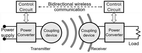
Figure 1.
A conceptual layout of the WPT mechanism.
1.3. Historical Development
The concept of wireless energy transmission dates back to the late 19th century. Nikola Tesla, a pioneer in electromagnetism, conducted the first major experiments in 1899 at Colorado Springs. Tesla envisioned a “World Wireless System” using the Wardenclyffe Tower to transmit electrical energy through the Earth and ionosphere [10]. However, his approach relied on standing waves and faced insurmountable challenges regarding radiative losses and lack of funding, leading to the project’s abandonment in 1906 [11].
It was not until the 1960s that William Brown successfully demonstrated microwave power transmission (MPT) for powering a tethered helicopter, establishing the foundation for far-field WPT [12,13,14]. A significant breakthrough in near-field technology occurred in 2007, when a team at MIT demonstrated strongly coupled magnetic resonance, lighting a 60W bulb over a distance of 2 m with 40% efficiency [15,16,17]. This rediscovery paved the way for modern mid-range inductive charging systems used in Electric Vehicles (EVs) today [18,19].
1.4. Contributions and Justification of Novelty
While numerous reviews exist in the literature, they typically focus on isolated aspects of WPT, such as specific coupling mechanisms (inductive vs. capacitive) or specific applications (EV charging only). This paper distinguishes itself from existing surveys by proposing a multidimensional classification framework that integrates emerging physical paradigms with practical operational constraints.
The specific contributions of this review are:
- A Novel Classification Framework: Unlike traditional taxonomies that classify solely by frequency, our framework (presented in Section 2) categorizes WPT systems by operational logic, integrating emerging technologies such as AI-optimized adaptive tuning and Parity–Time (PT) symmetric (Quantum) transfer.
- Holistic Technical Comparison: We provide a critical analysis of the design trade-offs between Inductive Power Transfer (IPT) and Capacitive Power Transfer (CPT), specifically addressing voltage stress, misalignment tolerance, and safety compliance.
- Economic and Regulatory Analysis: Beyond the physics, this review evaluates the Total Cost of Ownership (TCO) for WPT deployment in automotive and industrial sectors and summarizes the current regulatory landscape (ICNIRP, IEEE) regarding human safety.
- Forward-Looking Research Gaps: We identify specific bottlenecks in current technology, particularly the efficiency limitations of far-field systems and the standardization needs for dynamic EV charging.
Therefore, this analysis serves as a bridge between fundamental physics and practical deployment, offering valuable references for researchers seeking to understand the integration of hybrid and intelligent WPT systems.
2. Classifications of WPT
2.1. Classical Classifications of WPT
WPT technologies can be broadly classified into two main categories based on the distance and method of energy transfer—Near-Field and Far-Field [20,21,22]—as presented in Figure 2.
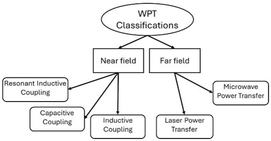
Figure 2.
Existing classifications of WPT into near- and far-field.
A key distinction exists between near-field and far-field approaches. Near-field techniques are typically employed over short distances between the transmitter and receiver [23,24,25,26], and they are non-radiative. These methods transfer energy through coupling strategies such as magnetic resonant coupling, inductive coupling, and capacitive coupling [27,28]. On the other hand, far-field techniques can achieve greater distances than other methods. They rely on electromagnetic radiation to transmit power wirelessly [29,30]. This approach is divided into two main types: optical power transmission (such as laser power transfer) and microwave power transmission.
2.2. Novel Classifications of WPT
WPT technologies have evolved significantly, with diverse methods tailored for different applications, power levels, and transmission environments. In this section, we introduce a novel classification framework, as shown in Figure 3 and Figure 4, that categorizes WPT technologies based on energy transfer mechanisms, application domains, power levels, and emerging systems such as AI and Quantum WPT.
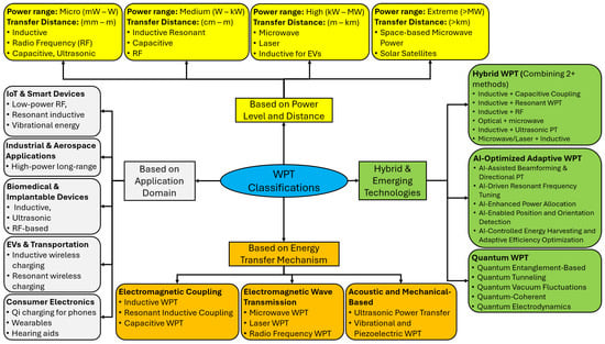
Figure 3.
Proposed WPT classification framework (Part I).
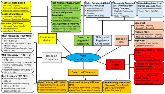
Figure 4.
Proposed WPT classification framework (Part II).
3. Near-Field and Far-Field WPT Technologies
3.1. Near-Field WPT (Non-Radiative)
Near-field Wireless Power Transfer, strictly defined as non-radiative coupling, operates within the reactive near-field region where the transmission distance (d) is much smaller than the wavelength () of the electromagnetic field () [31]. In this regime, energy is stored in the oscillating field rather than radiating into free space. This category is fundamentally divided into two topologies based on the field component utilized for energy exchange: Inductive Power Transfer (IPT), which relies on magnetic fields (H-field), and Capacitive Power Transfer (CPT), which utilizes electric fields (E-field).
Inductive Coupling is the dominant mechanism for high-power applications. It operates on the principle of Faraday’s Law of Induction, where a time-varying current in a primary transmitter coil generates an oscillating magnetic flux. This flux intersects a secondary receiver coil, inducing an electromotive force (EMF) [32]. In standard inductive systems (tightly coupled), efficiency relies heavily on physical proximity. However, modern high-efficiency systems utilize Resonant Inductive Coupling. By introducing compensation capacitors to form a resonant tank circuit, the system cancels the leakage inductance reactance. This allows for high-efficiency power transfer even at lower coupling coefficients () and extends the effective range from millimeters to tens of centimeters.
Capacitive Coupling, conversely, employs the displacement current principle. The transmitter and receiver plates form a virtual capacitor, transferring energy via high-frequency electric fields through a dielectric medium (typically air). While CPT eliminates the need for heavy magnetic cores and Litz wire, it faces high impedance challenges, often requiring operation at higher frequencies (MHz range) to achieve sufficient power density.
These near-field technologies are characterized by high transfer efficiency (>85%) and safety, as the non-radiative fields decay rapidly () with distance, minimizing interference with long-range communications.
3.1.1. Inductive Coupling Power Transfer (IPT)
Inductive Power Transfer (IPT) is the most established WPT technology, fundamentally governed by Ampere’s Circuital Law and Faraday’s Law of Induction. As depicted in Figure 5, the system consists of a primary (transmitter) and a secondary (receiver) side.
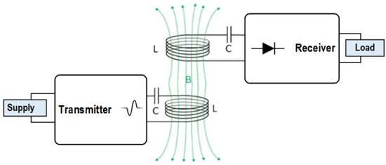
Figure 5.
Diagram of an Inductive Power Transfer (IPT) system highlighting the resonant compensation stage.
Fundamental Mechanism: The process begins with a high-frequency inverter converting the DC source into an AC current (typically 85 kHz to 140 kHz). Following Ampere’s Law, this oscillating current flowing through the transmitter coil generates a time-varying magnetic flux field (). When this flux intersects the receiver coil, it induces an electromotive force (EMF) according to Faraday’s Law (). This induced AC voltage is subsequently rectified to charge a battery or power a load [33].
Resonance and Compensation: A standard inductive link behaves like a loosely coupled air-core transformer with high leakage inductance. To transfer significant power without massive reactive current losses, **impedance compensation networks** (capacitors arranged in series or parallel topologies) are mandatory. These capacitors resonate with the coil inductance, canceling the leakage reactance and allowing the system to operate at a high Power Factor [34,35]. The quality of this link is defined by the coupling coefficient (k) and the coil quality factor (Q). High-efficiency systems utilize **Litz wire** to minimize skin-effect losses and **ferrite cores** to guide the magnetic flux and improve coupling [36].
Performance Analysis: Table 1 summarizes the performance of various implemented IPT systems. The data illustrates a fundamental trade-off: as the transmission distance increases, the magnetic coupling (k) decreases exponentially, leading to a rapid drop in efficiency unless the coil size is increased.

Table 1.
Performance Summary of State-of-the-Art IPT Systems.
Optimal efficiency (>90%) is achieved when the receiver is within the “reactive near-field” region, typically a distance less than half the coil diameter [37,38]. Misalignment significantly degrades the mutual inductance, necessitating precise parking in EV applications or adaptive tuning circuits [39].
3.1.2. Capacitive Coupling Power Transfer (CPT)
Unlike the magnetic fields used in IPT, Capacitive Power Transfer (CPT) utilizes high-frequency electric fields (E) to transmit energy. The fundamental mechanism relies on **Maxwell’s displacement current**. As illustrated in Figure 6, the system typically employs two pairs of conductive metal plates (couplers) separated by a dielectric medium (air, glass, or plastic) to form a capacitor network.
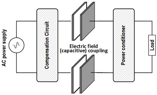
Figure 6.
Block diagram of a Capacitive Power Transfer (CPT) system showing the electric field coupling.
Fundamental Challenge: The primary engineering challenge in CPT is the extremely small coupling capacitance (), typically ranging from picofarads (pF) to a few nanofarads (nF). According to the impedance formula , a small capacitance results in extremely high impedance. To drive sufficient power through this high-impedance link, CPT systems must operate at:
- High Frequencies: Typically in the MHz range (1 MHz–13.56 MHz) to lower the reactance.
- High Voltages: Utilizing step-up transformers or resonant networks to generate kilovolts (kV) across the plates [40].
Compensation Topologies: To match the high impedance of the plates to the low impedance of the inverter, high-order compensation networks are essential. As shown in Table 2, early designs used simple LC compensations, but modern systems utilize **LCL, LCLC, or CLLC** topologies. These networks function as impedance matching circuits, boosting the voltage across the plates while maintaining a unity power factor at the inverter output.
Cross-Coupling and Interference: In multi-plate systems, “cross-coupling” refers to the parasitic capacitance between non-paired plates (e.g., transmitter plate 1 to receiver plate 2). Unlike inductive cross-coupling, capacitive cross-coupling can be beneficial if managed correctly, but uncontrolled parasitic capacitance leads to leakage currents and electromagnetic interference (EMI), requiring strict shielding [41,42,43].
Table 2.
Performance Summary of State-of-the-Art CPT Systems.
Table 2.
Performance Summary of State-of-the-Art CPT Systems.
| Air Gap (mm) | Topology | Power (W) | Freq. (f) | Efficiency () |
|---|---|---|---|---|
| 180 | LC–LC | 150 | 1.5 MHz | 66.7% [44] |
| 2000 | LC–LC | 216.5 | 1 MHz | 52.2% [45] |
| 150 | LCL-LCL | 1880 | 1 MHz | 85.9% [46] |
| <10 | Modified LLC | 1000 | 250 kHz | 94.0% [47] |
| 110 | Series L | 350 | 6.78 MHz | 70.0% [48] |
| 150 | CLLC-CLLC | 2570 | 1 MHz | 89.3% [49] |
| 150 | LCLC-LCLC | 2400 | 1 MHz | 90.8% [50] |
3.1.3. Comparative Analysis and Design Trade-Offs: IPT vs. CPT
While both inductive and capacitive topologies operate on near-field resonance, their design challenges are diametrically opposed due to the nature of the fields utilized [44,51].
Inductive Power Transfer (IPT) relies on magnetic fields (H-field) generated by high currents.
- Advantages: IPT offers high power density and is capable of transferring kilowatts at relatively low frequencies (85 kHz–140 kHz). It is the dominant standard (Qi, SAE J2954 [52]).
- Limitations: The primary drawback of IPT is the generation of eddy currents in foreign metallic objects (coins, keys), necessitating complex Foreign Object Detection (FOD). Furthermore, IPT systems utilize heavy ferrite cores [45].
Capacitive Power Transfer (CPT) relies on electric fields (E-field) generated by high voltages.
- Advantages: CPT eliminates the need for expensive magnetic cores and Litz wire, utilizing lightweight metal plates instead [46,47].
- Limitations: The primary challenge in CPT is the “Voltage Stress” limitation. Because the coupling capacitance across an air gap is typically very small, the reactance is high, often requiring LC-compensation networks to achieve resonance [48,49]. This introduces safety concerns regarding dielectric breakdown (arcing).
Hybrid Approaches: Recent literature suggests hybrid IPT-CPT topologies to leverage the strengths of both. By combining the high-current characteristics of IPT with the voltage-driven nature of CPT, these hybrid compensations can optimize the power factor and reduce the stress on individual components [50,53,54,55,56]. Table 3 summarizes these trade-offs.
Table 3.
Critical Design Trade-offs between IPT and CPT Technologies.
3.2. Far-Field WPT (Radiative)
Far-field wireless power transfer, scientifically termed radiative power transfer, operates in the Fraunhofer region, where the transmission distance (d) significantly exceeds the wavelength (, where D is the antenna dimension). Unlike near-field methods that rely on reactive magnetic or electric fields, far-field systems transmit energy via propagating transverse electromagnetic (TEM) waves.
Fundamental Physics and Challenges: The efficiency of far-field transmission is fundamentally governed by the **Friis Transmission Equation** and the **Inverse Square Law**, which dictate that power density attenuates proportionally to the square of the distance (). Consequently, the primary engineering challenge is to minimize beam divergence. To achieve high efficiency over long distances, the system requires:
- High Directivity: Using phased array antennas (for microwaves) or collimated optics (for lasers) to focus the energy into a narrow beam.
- High Frequency: Increasing the frequency (f) allows for smaller transmission apertures, as the beam diffraction is proportional to .
Modality Comparison: Far-field WPT is categorized into two distinct modalities based on the electromagnetic spectrum utilized:
- Laser Power Transfer (LPT): Operates in the optical spectrum (THz range). LPT offers extremely high power density and compact apertures due to the nanometer-scale wavelength but is strictly limited by Line-of-Sight (LoS) requirements and atmospheric attenuation.
- Microwave Power Transfer (MPT): Operates in the Radio Frequency (RF) spectrum (typically 2.45 GHz or 5.8 GHz ISM bands). MPT can penetrate atmospheric conditions like clouds and rain but requires large rectenna arrays to harvest the diffracted beam.
While far-field technologies enable unique applications such as Solar Power Satellites (SBSP) and UAV charging, they are currently constrained by low end-to-end efficiency (<40%) and strict regulatory limits on Electromagnetic Radiation (EMR) exposure.
3.2.1. Laser Power Transfer (LPT)
Laser Power Transfer (LPT), often referred to as Optical Wireless Power Transmission (OWPT), relies on the conversion of electrical energy into a highly collimated beam of monochromatic light (photons), which is transmitted through free space and reconverted into electricity by a specialized photovoltaic (PV) receiver.
System Architecture and Efficiency Budget: As illustrated in Figure 7, the LPT architecture consists of three distinct stages, each contributing to the total system efficiency ():
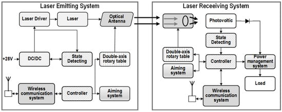
Figure 7.
Architecture of the Laser Power Transfer (LPT) system showing the E-O-E conversion chain.
- Laser Source: High-power laser diodes or fiber lasers convert DC power into a coherent beam. While modern solid-state lasers have improved, the “wall-plug efficiency” () typically remains between 40% and 60%, representing a significant thermal management challenge.
- Transmission Medium: Unlike RF waves, laser beams are tightly collimated, minimizing diffraction losses over distance. However, they are highly susceptible to atmospheric attenuation caused by scattering (fog, dust) and absorption (rain), which degrades in outdoor environments.
- PV Receiver: Standard silicon solar cells are inefficient for LPT because they are designed for the broad solar spectrum. High-efficiency LPT systems utilize **monochromatic PV cells** (e.g., Gallium Arsenide—GaAs) tuned specifically to the laser’s wavelength, achieving conversion efficiencies () of 40–60% [57,58].
Advantages and Specialized Applications: Despite lower end-to-end efficiency compared to inductive methods, LPT offers unique advantages in electromagnetic compatibility (EMC). As shown in Figure 8, LPT is ideal for powering sensors in **High-Voltage (HV) transmission lines** or hazardous environments (e.g., fuel tanks) because the energy transfer is optical, not electromagnetic. It produces no Radio Frequency Interference (RFI) and is immune to external electromagnetic [59]. Furthermore, LPT enables **Simultaneous Wireless Information and Power Transfer (SWIPT)**, where the laser beam is modulated to carry high-speed data alongside power [60].
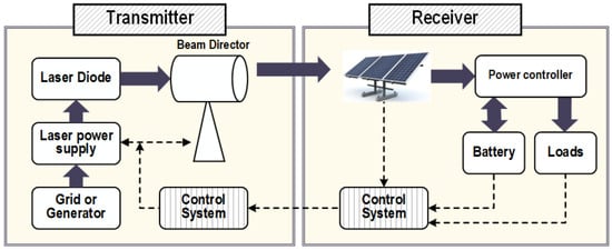
Figure 8.
Application of LPT for powering sensors in high-voltage or hazardous environments (HILPB).
Safety and Regulatory Constraints: The primary barrier to commercial LPT deployment is ocular safety. High-power laser beams fall under **IEC 60825-1 Class 4** [61] regulations, which are hazardous to the eye and skin. To operate in public spaces, systems must adhere to strict **Maximum Permissible Exposure (MPE)** limits. Modern LPT systems incorporate active safety mechanisms, such as “virtual guard rings” or low-power retro-reflective scanning, to instantly shut down the beam if an obstruction (human or object) is detected [59,62].
Table 4 summarizes the performance of various LPT experimental setups, highlighting the dependence of efficiency on wavelength and PV material [63,64,65,66,67].
Table 4.
Performance Summary of State-of-the-Art Laser Power Transfer Technologies.
3.2.2. Microwave Power Transfer (MPT)
Microwave Power Transfer (MPT) is the most established far-field technology, characterized by the conversion of DC power into microwave Radio Frequency (RF) energy, which is beamed through free space and rectified back to DC at the receiver. As shown in Figure 9, the end-to-end system architecture is defined by three critical conversion stages.
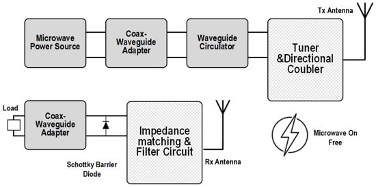
Figure 9.
Block diagram of the Microwave Power Transfer (MPT) conversion chain.
1. DC-to-RF Conversion (Transmission): The transmitter converts electrical energy into microwaves using either high-power vacuum tubes (Magnetrons/Klystrons) or modern **Solid State Power Amplifiers (SSPAs)**. While magnetrons offer high efficiency (>70%) and low cost, SSPAs are preferred in modern research for their ability to support **active phased array beamforming**. This technique allows the beam to be electronically steered and focused without mechanical movement, maximizing the power density at the receiver [68].
2. Beam Propagation and Frequency Selection: MPT typically operates in the **Industrial, Scientific, and Medical (ISM)** bands, specifically at **2.45 GHz** and **5.8 GHz** [69,70,71]. The choice of frequency is a trade-off:
- Lower Frequencies (e.g., 2.45 GHz): Offer lower atmospheric attenuation and cheaper components but require massive transmission apertures to maintain a focused beam (due to the diffraction limit).
- Higher Frequencies (e.g., 35 GHz–94 GHz): Allow for compact antennas suitable for drones or satellites but suffer from higher switching losses and atmospheric absorption (rain fade) [72].
3. RF-to-DC Rectification (The Rectenna): The receiver, termed a **Rectenna** (Rectifying Antenna), captures the incident microwave beam. It consists of an antenna array integrated with a rectifying circuit, typically utilizing **Schottky barrier diodes** due to their low turn-on voltage and fast switching speeds. As illustrated in Figure 10, the matching network is critical to minimize reflection losses between the antenna impedance and the nonlinear diode impedance.
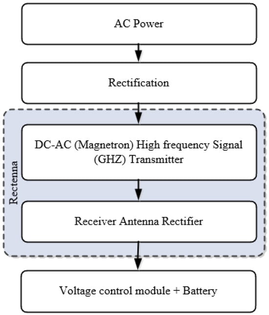
Figure 10.
Core flowchart depicting the MPT topology and rectification process.
Current Limitations: Despite its potential for Space-Based Solar Power (SBSP), MPT faces the “Gaussian Beam” challenge: energy distribution in the beam is non-uniform, leading to lower conversion efficiency at the edges of the rectenna. Furthermore, maintaining high rectification efficiency (>80%) requires a constant, optimized input power density, which is difficult to sustain over long distances due to path loss [73,74].
Table 5 summarizes the performance of notable MPT implementations, highlighting the disparity between short-range high efficiency and long-range attenuation.
Table 5.
Performance Summary of Implemented MPT Systems.
3.3. Comparison and Selection Criteria: Near-Field vs. Far-Field
The selection between near-field and far-field topologies is fundamentally dictated by the application’s required transmission distance relative to the operating wavelength ().
Physical Boundary Definition: The transition from near-field to far-field is not abrupt but is scientifically defined by the **Radian Sphere** ().
- Reactive Near-Field (): Energy is stored in the magnetic or electric field and oscillates between the source and load without radiating into space. This regime (IPT/CPT) allows for high efficiency (>90%) but requires the receiver to be within the “bubble” of stored energy. Field strength decays rapidly at [81].
- Radiative Far-Field (): Energy detaches from the source and propagates as electromagnetic waves. This regime (MPT/LPT) enables long-range transmission but is governed by the Inverse Square Law (), leading to significant path loss unless highly directive beamforming is employed.
Operational Trade-offs: As summarized in Table 6, the trade-off is binary: Near-field offers high efficiency and safety (non-ionizing, non-radiative) but is tethered to short ranges. Far-field offers mobility and range but requires strict safety protocols (due to propagating radiation) and suffers from atmospheric and diffraction losses.
Table 6.
Comparative Analysis of Near-Field and Far-Field WPT Technologies.
3.4. Emerging and Hybrid WPT Classifications
The novel classification framework presented in Figure 3 integrates emerging physical mechanisms that extend beyond traditional inductive and radiative methods. These categories represent the frontier of WPT research, addressing specific limitations regarding metallic shielding, dynamic response time, and non-linear distance variations.
3.4.1. Acoustic and Ultrasonic Power Transfer (UPT)
While inductive coupling suffers from attenuation in metallic environments (Faraday shielding) and strict SAR limits in biological tissue, Acoustic Power Transfer utilizes mechanical vibrations (typically 20 kHz–10 MHz) to transmit energy.
- Mechanism: The system utilizes piezoelectric transducers (typically PZT ceramics) to convert electrical energy into ultrasonic waves. These waves propagate through a medium (tissue, water, or metal walls) and are reconverted into electricity by a receiver transducer via the direct piezoelectric effect.
- Scientific Advantage: The speed of sound in tissue (≈1540 m/s) is orders of magnitude slower than the speed of light. Consequently, the wavelength () at 1 MHz is roughly 1.5 mm. This allows for the design of millimeter-scale receivers that are highly efficient, whereas an RF antenna at 1 MHz would be meters long. This physics makes UPT dominant for deep-tissue biomedical implants where EM waves are absorbed [82,83,84].
3.4.2. AI-Optimized and Adaptive WPT
Modern dynamic WPT systems are increasingly defined by their control logic rather than just coil physics. The non-linear relationship between misalignment, mutual inductance (M), and reflected impedance makes traditional PID control insufficient for fast-moving receivers.
- Mechanism: AI-Optimized WPT employs Machine Learning algorithms, specifically Deep Reinforcement Learning (DRL) and Convolutional Neural Networks (CNN). These algorithms monitor the input voltage/current waveforms and dynamically tune the variable capacitors in the Impedance Matching Network (IMN).
- Added Value: Unlike look-up tables, AI agents can “predict” the trajectory of an EV or drone, pre-tuning the circuit to maintain Zero Voltage Switching (ZVS) and peak efficiency before the misalignment event occurs [85].
3.4.3. Quantum-Inspired (PT-Symmetric) WPT
The “Quantum” category in Figure 3 refers to macro-scale systems utilizing Parity–Time (PT) Symmetry, a concept originating from non-Hermitian quantum mechanics.
- Mechanism: A PT-symmetric system consists of two coupled resonators: one with active gain (negative resistance via operational amplifiers) and one with loss (the load).
- The Physics of “Locking”: Unlike standard resonant coupling where efficiency drops sharply if the distance changes, a PT-symmetric system enters a “broken phase” where the operating frequency automatically splits to match the distance. This allows the system to maintain constant, high efficiency over a varying range without manual frequency tuning or complex feedback loops, theoretically solving the distance-sensitivity problem of magnetic resonance [86].
3.4.4. Quantum and PT-Symmetric WPT
The “Quantum” category in Figure 3 refers to “Quantum-inspired” macro-scale systems utilizing Parity–Time (PT) Symmetry. Originating from quantum mechanics, PT-symmetry applied to WPT involves coupled resonators with balanced gain and loss, enabling constant efficiency over varying distances without manual tuning [86].
4. Applications of WPT
WPT technologies have matured from theoretical prototypes to commercially deployed systems across distinct power classes. Applications are generally categorized by power level and transmission distance: low-power near-field systems for consumer electronics (<100 W), medium-to-high-power near-field systems for automotive and industrial transport (3 kW–200 kW), and high-power far-field systems for remote energy transmission.
4.1. Automotive Sector (EV Charging)
The automotive sector represents the largest market for high-power WPT. Applications are divided into Stationary (Static) and Dynamic (In-Motion) charging.
- Stationary Charging: Governed by the SAE J2954 standard, this technology utilizes resonant inductive coupling at 85 kHz. Systems typically operate at power levels of 3.7 kW (WPT1), 7.7 kW (WPT2), and 11 kW (WPT3), with efficiencies exceeding 90% at air gaps of 100–250 mm. The primary engineering benefit is the facilitation of Vehicle-to-Grid (V2G) integration without user intervention, as illustrated in Figure 11.
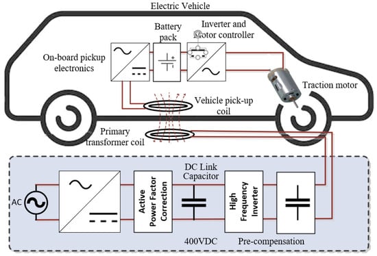 Figure 11. Typical EV charging system architecture showing grid-to-vehicle integration.
 - Dynamic Wireless Power Transfer (DWPT): DWPT involves embedding transmitter coils into road infrastructure to power vehicles in motion. While this theoretically allows for infinite range and significantly smaller onboard batteries, it faces substantial challenges regarding infrastructure cost ($1.7 M/km) and the complexity of fast receiver switching between track segments [84,87,88].
4.2. Biomedical Implants and Wearables
In the biomedical domain, WPT addresses the critical infection risk associated with percutaneous (through-the-skin) drivelines.
- Implantable Devices: For high-power implants like Left Ventricular Assist Devices (LVADs) or artificial hearts, Transcutaneous Energy Transfer (TET) systems transfer 5–20 W through the skin. Research focuses on optimizing coil misalignment tolerance and minimizing tissue heating (SAR) to comply with IEEE C95.1 [89] safety limits.
- Miniaturized Sensors: For deep-tissue implants (e.g., pacemakers, neural dust), ultrasonic or low-frequency inductive links are preferred to penetrate tissue with minimal attenuation. These systems eliminate the need for invasive surgical battery replacements, significantly improving patient outcomes [90,91].
4.3. Smart Home and Consumer Electronics
Beyond the pervasive “Qi” standard (5–15 W) for mobile devices, the WPT ecosystem is expanding to high-power kitchen appliances. The Wireless Power Consortium (WPC) has introduced the **“Ki” Cordless Kitchen standard**, which delivers up to **2.2 kW** to appliances (blenders, rice cookers) via near-field induction transmitters hidden beneath non-metallic countertops. These systems utilize Near Field Communication (NFC) for intelligent control and Foreign Object Detection (FOD) to ensure safety [92,93,94].
4.4. Wireless Powered Light Rail Vehicle (LRV)
For mass transit, WPT offers an alternative to overhead catenary wires, which are visually intrusive and maintenance-heavy. LRV applications require significantly higher power levels (typically >200 kW) transferred during short dwell times at stations (“Opportunity Charging”). Research indicates that while Inductive Power Transfer (IPT) is the standard, Capacitive Power Transfer (CPT) is being investigated for rail applications due to its ability to utilize the large surface area of the train undercarriage as a coupling plate, potentially reducing the weight of ferrite cores required by IPT systems [95,96,97].
4.5. Space-Based Solar Power (SBSP)
SBSP represents the ultimate application of Far-Field WPT. The concept involves geostationary satellites harvesting solar energy continuously (unaffected by night or weather) and beaming it to Earth via microwaves (typically 2.45 GHz or 5.8 GHz).
- Transmission Mechanism: As shown in Figure 12, the satellite converts DC power to RF energy, which is focused onto a ground-based “Rectenna” (Rectifying Antenna) array spanning several kilometers.
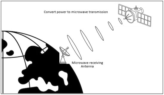 Figure 12. Concept of Solar Power Satellites (SBSP) utilizing microwave transmission from orbit.
 - Challenges: The primary barriers are the diffraction limit (requiring massive apertures for efficient transmission) and atmospheric attenuation. Current research focuses on improving the RF-to-DC conversion efficiency of rectennas and ensuring beam safety [93].
5. WPT Standards and Interoperability Protocols
Standardization is the critical enabler for mass adoption of WPT technologies, ensuring that devices from different manufacturers can operate seamlessly (interoperability) while adhering to strict safety limits. Standards are generally categorized into two domains: Consumer Electronics (low power/short range) and Electric Vehicles (high power/medium range) [98,99,100].
5.1. Consumer Electronics Standards
The consumer market is dominated by the **Wireless Power Consortium (WPC)**, which manages the “Qi” standard.
- Qi (Inductive): Operating between 87 and 205 kHz, Qi relies on tight magnetic coupling and in-band communication (load modulation) for feedback control. It currently dominates the smartphone market, offering power profiles from 5 W (Baseline Power Profile) to 15 W (Extended Power Profile).
- Ki (Cordless Kitchen): A newer WPC standard designed for kitchen appliances (blenders, rice cookers) that delivers up to 2.2 kW using near-field induction transmitters embedded in countertops [101].
- AirFuel Alliance (Resonant): Operating at the ISM frequency of 6.78 MHz, AirFuel Resonant (formerly A4WP) allows for greater spatial freedom and multi-device charging. However, due to the complexity of 6.78 MHz power electronics, it has seen lower adoption compared to Qi [102,103].
5.2. Automotive and Infrastructure Standards
For Electric Vehicles, standardization focuses on safety, high power transfer, and alignment tolerance. The dominant standard is **SAE J2954**, which defines the following parameters to ensure interoperability between vehicle pads (VA) and ground pads (GA):
- Frequency: A unified operating band at **85 kHz** (81.38–90 kHz) to minimize interference with automotive key fobs and AM radio.
- Power Classes: Defined levels including WPT1 (3.7 kW), WPT2 (7.7 kW), and WPT3 (11 kW), with future extensions for heavy-duty vehicles (WPT4 at 22 kW+).
- Z-Classes (Air Gap): Standards define vertical operating gaps ranging from Z1 (100–150 mm) for sports cars to Z3 (170–250 mm) for SUVs.
Parallel to SAE, the **IEC 61980** series governs the supply infrastructure and safety requirements for wireless power transfer from the grid side.
Table 7 summarizes the technical specifications of the current prevailing standards.
Table 7.
Technical Specifications of Major WPT Standards.
6. Analysis of Economic Factors and Policy Implications
The broad adoption of WPT technology is not solely determined by technical feasibility but by its economic competitiveness against mature wired solutions. As highlighted by recent techno-economic reviews [95,98,106], the viability of WPT is governed by a trade-off between higher upfront Capital Expenditure (CAPEX) and reduced long-term Operational Expenditure (OPEX). This section analyzes the Total Cost of Ownership (TCO) across three distinct sectors.
6.1. Automotive Sector: The TCO Divergence
In the electric vehicle market, the economic justification for WPT differs sharply between private passenger vehicles and commercial fleets.
- Private Passenger Vehicles (The Convenience Premium): For consumer EVs, WPT is currently a luxury add-on. A stationary 11 kW wireless charging system typically incurs a hardware cost premium of 30–50% compared to a standard wired Level 2 wallbox. This is due to the additional cost of the ground pad (ferrites, litz wire), the vehicle assembly (compensation network), and the safety systems (FOD detection). For the average consumer, this represents a “Convenience Premium” rather than a financial investment.
- Commercial Fleets (The TCO Advantage): For transit buses and logistics trucks, WPT shifts from a luxury to a cost-saving mechanism. A comparative lifecycle analysis of airport shuttle fleets [106] demonstrated that while WPT infrastructure requires high initial investment, it enables battery downsizing. By utilizing high-power opportunity charging (50 kW+) at scheduled stops, buses can operate with smaller, lighter battery packs (reducing vehicle weight by up to 46%). Over a 12-year lifecycle, a wireless bus fleet was projected to cost $44.5 million, compared to $47.3 million for plug-in electric buses and $60.1 million for diesel. The savings are driven by reduced battery replacement costs and the elimination of manual labor for plugging/unplugging.
- Dynamic WPT (The Infrastructure Barrier): While technically feasible, Dynamic Wireless Power Transfer (DWPT) or “charging lanes” faces immense economic hurdles. Recent estimates place the electrification cost of highways between $1.7 million and $3.5 million per kilometer [107]. Consequently, DWPT is currently economically justifiable only for high-density freight corridors where the reduction in onboard battery weight for heavy-duty trucks offsets the massive infrastructure investment.
6.2. Industrial IoT: The “Truck Roll” Economics
In the domain of the Internet of Things (IoT) and industrial sensors, the economic driver is not the cost of electricity, but the cost of maintenance labor (often termed the “truck roll” cost).
- Maintenance vs. Hardware Cost: A battery-powered sensor node is cheap to manufacture ($10–$20) but expensive to maintain. In hazardous or inaccessible environments (e.g., bridge structural health monitoring or mining shafts), the labor cost to deploy a technician to replace a single battery can range from $300 to $600 per visit [108].
- The Payback Period: WPT (specifically RF harvesting or long-range microwave transfer) increases the initial hardware cost of the sensor node. However, by enabling “deploy-and-forget” operation, the technology achieves return on investment (ROI) immediately after avoiding the first required battery replacement cycle.
6.3. Grid Implications and the “Efficiency Tax”
From a policy and utility perspective, the widespread adoption of WPT introduces an “Efficiency Tax”—the aggregate energy lost due to the lower efficiency of wireless links compared to wired connections.
- The Efficiency Gap: Modern resonant inductive systems achieve grid-to-battery efficiencies of 88–93%, roughly 5–7% lower than conductive AC charging.
- Consumer vs. Utility Impact: For an individual EV driver covering 20,000 km/year, this efficiency drop translates to approximately 200–300 kWh of wasted energy annually, costing roughly $40–$50. While negligible for the individual, at a grid scale comprising millions of vehicles, this represents gigawatt-hours of additional load. Policymakers must therefore balance the incentives for WPT (to encourage EV adoption via convenience) with strict minimum efficiency standards (such as those in SAE J2954) to prevent excessive grid strain.
7. Measurement Methods and Performance Evaluation
Accurate evaluation of WPT systems presents unique metrological challenges that do not exist in standard 50/60 Hz power grid distribution. WPT systems typically operate at high frequencies (kHz to MHz), involve non-sinusoidal switching waveforms, and often exhibit very low power factors () within the resonant tank, even if the input/output are DC. Consequently, standard multimeters or low-bandwidth oscilloscopes yield significant errors. A structured measurement framework is required to assess three critical domains: Power Efficiency, Magnetic Coupling/Misalignment, and Electromagnetic Compatibility (EMC) [106].
7.1. Efficiency and Electrical Characterization
The most critical metric, Power Transfer Efficiency (PTE), defines the ratio of useful output power to input power.
- System-Level Efficiency (DC-DC): This encompasses losses in the inverter, resonator coils, and rectifier. Accurate measurement requires **High-Bandwidth Precision Power Analyzers**. These instruments must simultaneously sample voltage and current at high rates (typically >2 MS/s) to capture the harmonic content of the square-wave switching signal. A common error source is the “phase error” in current probes; at high frequencies, even a small phase delay in the probe can lead to massive errors in calculating active power () when the phase angle is near 90°.
- Resonator Efficiency (Coil-to-Coil): To isolate the physics of the magnetic link from the electronics, Vector Network Analyzers (VNAs) are the industry standard. VNAs measure Scattering parameters (S-parameters) [107]. The forward transmission coefficient () is used to derive the link efficiency. While highly precise for characterizing resonance frequency and bandwidth, VNAs typically operate at milliwatt power levels (“small signal”). This is a limitation because it fails to account for “large signal” non-linearities, such as ferrite core saturation or thermal drift that occurs during actual high-power operation [102].
7.2. Magnetic Coupling and Misalignment Tracking
In dynamic applications like EV charging, the system must characterize the magnetic link state before energizing high power.
- LCR Meters: For static characterization, LCR meters are used to measure self-inductance (L) and series resistance () at the specific operating frequency. Mutual inductance (M) is derived by measuring the series-aiding and series-opposing inductance of connected coils.
- Reflected Impedance Estimation (DMRI): In active control scenarios, the transmitter controller monitors its own input impedance (). As the receiver moves or misaligns, the reflected impedance changes. Advanced controllers use this data to estimate the coupling coefficient (k) and distance in real time without requiring external optical or mechanical sensors [103].
7.3. Safety (EMF) and Regulatory (EMC) Compliance
Regulatory testing is divided into two distinct categories: Human Safety (EMF) and Device Interference (EMC).
- Human Safety (SAR/ICNIRP): To ensure compliance with ICNIRP guidelines, Isotropic Field Probes are used to map the electric (E) and magnetic (H) field strength in the 3D space surrounding the charger. For specific absorption rate (SAR) assessment in biomedical implants, Phantom Models (robotically controlled probes inside a liquid-filled shell mimicking human tissue properties) are used to measure localized energy absorption.
- Electromagnetic Compatibility (EMC): To ensure the WPT charger does not interfere with other electronics (like a car’s key fob or radio), radiated emissions are measured in an Anechoic Chamber using wideband antennas and Spectrum Analyzers, strictly following standards such as CISPR 11 [109] (Industrial, Scientific and Medical equipment).
Table 8 summarizes the structured measurement methodology, comparing the advantages and physical limitations of each instrument class.
Table 8.
Structured Overview of Measurement Methodologies for WPT Systems.
8. Health Impact of WPT
The proliferation of WPT technologies has raised legitimate concerns regarding human exposure to electromagnetic fields (EMF). The biological interaction with EMF depends heavily on the operating frequency and power level, necessitating a clear distinction between near-field and far-field exposure mechanisms. Compliance is generally assessed against guidelines established by the International Commission on Non-Ionizing Radiation Protection (ICNIRP) and the IEEE International Committee on Electromagnetic Safety (IEEE C95.1).
8.1. Near-Field Exposure: Induction and Stimulation
In near-field systems (IPT and CPT) operating in the kHz to low MHz range, the primary health concern is **electrostimulation** of nerve and muscle tissue.
- Magnetic Field Exposure: For Inductive Power Transfer (IPT), the high-current coils generate strong magnetic fields (H-field). Since magnetic fields permeate biological tissue with little attenuation, the primary safety metric is the internal electric field induced within the body, which must remain below thresholds that trigger involuntary nerve response. For high-power applications like EV charging (SAE J2954), shielding (aluminum and ferrite) is mandatory to keep the leakage flux density below the ICNIRP reference level (typically 27 μT for the general public at wireless charging frequencies).
- Active Implantable Medical Devices (AIMD): A critical subset of safety concerns involves interference with pacemakers and defibrillators. Even low-level fields acceptable for the general public can induce voltages in pacemaker leads, potentially disrupting cardiac monitoring. Consequently, WPT chargers often require “keep-out zones” for individuals with implants.
8.2. Far-Field Exposure: Thermal Effects
For radiative systems (Microwave and Laser) operating in the GHz to THz range, the photon energy is insufficient to cause ionization (DNA damage), but significant energy absorption occurs. The primary mechanism of interaction is **thermal heating**.
- Microwave Power Transfer (MPT): Exposure is governed by the Specific Absorption Rate (SAR), measured in Watts per kilogram (W/kg), which quantifies the rate of energy deposition in tissue. As frequency increases (e.g., 2.4 GHz to 28 GHz), the depth of penetration decreases, shifting the concern from deep-tissue heating to skin surface heating. MPT systems typically employ “exclusion zones” or beam-shutoff protocols if a human enters the transmission path to ensure power density remains below limits (e.g., 10 W/m2 for continuous public exposure).
- Laser Power Transfer (LPT): LPT systems operate in the optical or near-infrared spectrum. The human eye is the most vulnerable organ, as the cornea and lens focus the beam onto the retina, causing instantaneous thermal damage even at low power densities. LPT systems are classified under IEC 60825-1 standards and almost universally require Class 1 safety features, such as “virtual guard rings” or active detection systems that cut power within milliseconds if the line-of-sight is interrupted.
In summary, while WPT utilizes non-ionizing radiation, ensuring safety requires strict adherence to shielding protocols in near-field systems and active beam control in far-field systems. Current commercial systems (Qi, EV chargers) operating within standards pose minimal health risks to the general population.
9. Conclusions
This paper has presented a comprehensive review of Wireless Power Transfer (WPT) technologies, synthesizing the literature published between 2010 and 2025. Unlike traditional reviews that isolate coupling mechanisms, this work proposed a novel multi-dimensional classification framework. This framework categorizes WPT systems not only by physical layer (Inductive vs. Capacitive) but also by operational logic, integrating emerging paradigms such as AI-driven impedance matching and Parity–Time (PT) symmetric transfer.
9.1. Technical Synthesis and Comparative Outcomes
The comparative analysis of Near-Field and Far-Field technologies yields the following critical observations regarding the state-of-the-art:
- Near-Field Maturity vs. Constraints: Inductive Power Transfer (IPT) has established itself as the dominant standard for high-power applications (kW range), achieving DC-to-DC system efficiencies exceeding 90% in electric vehicle and consumer electronics sectors. However, its widespread integration is heavily constrained by the weight of ferrite cores and the safety risks associated with metal object heating (Eddy currents). In contrast, Capacitive Power Transfer (CPT) offers a lightweight, lower-cost alternative capable of penetrating metallic barriers, yet it remains limited by high voltage stress on components and lower overall power density (<10 kW typically).
- The Physics of Far-Field Limitations: While radiative technologies (Microwave and Laser) theoretically enable power transmission over kilometer-scale distances, they face a fundamental trade-off between beam safety and transfer efficiency. Current Microwave Power Transfer (MPT) systems struggle to exceed 40% end-to-end efficiency due to conversion losses (RF-to-DC) and diffraction limits. Laser Power Transfer (LPT) offers superior energy density for point-to-point applications but is severely compromised by atmospheric attenuation and strict ocular safety requirements, limiting its reliability in uncontrolled environments.
9.2. Future Research Directions
To overcome the current bottlenecks identified in this review, future research efforts must pivot towards the following areas:
- Hybrid Compensation Topologies: Developing hybrid LCC-LCC or IPT-CPT coupler structures that combine the high-current capabilities of magnetic coupling with the electric-field advantages of capacitive coupling to improve misalignment tolerance.
- Wide Bandgap (WBG) Integration: The adoption of Gallium Nitride (GaN) and Silicon Carbide (SiC) devices in the inverter stage to push switching frequencies into the MHz range, thereby reducing the size of passive components and enabling higher efficiency in CPT systems.
- AI-Driven Dynamic Control: Moving beyond fixed-frequency tuning by integrating Machine Learning algorithms (such as Reinforcement Learning) to dynamically adjust impedance matching networks in real time. This is essential for maintaining efficiency in dynamic EV charging scenarios where coupling varies continuously.
- Standardization of Metrics: The academic community must adopt unified reporting standards that clearly distinguish between “Coil-to-Coil efficiency” and “System-level efficiency” to prevent misleading performance claims. Furthermore, standardized protocols for measuring biological safety (SAR) in high-power near-field systems are urgently needed to facilitate regulatory approval.
In summary, while WPT has matured from a theoretical concept to a commercial reality in the low-power domain, its expansion into high-power industrial and automotive sectors requires solving the multi-objective optimization problem of efficiency, misalignment tolerance, and biological safety.
Author Contributions
Conceptualization, A.B., I.M.E. and C.Z.E.-b.; methodology, A.B., I.M.E., C.Z.E.-b., W.A. and A.M.Z.; software, A.B., I.M.E., C.Z.E.-b. and W.A.; validation, A.B., I.M.E., C.Z.E.-b., A.M.Z. and W.G.; formal analysis, A.B.; investigation, W.A. and W.G.; writing—original draft preparation, A.B., I.M.E., C.Z.E.-b., W.A. and A.M.Z.; writing—review and editing, A.B., I.M.E., C.Z.E.-b., W.A., A.M.Z. and W.G.; visualization, I.M.E., C.Z.E.-b., W.A. and W.G.; supervision, A.B.; project administration, A.B.; funding acquisition, A.B. and I.M.E. All authors have read and agreed to the published version of the manuscript.
Funding
This research was funded by Qatar National Research Fund (QNRF) under the Undergrad-uate Research Experience Program (UREP), Project No. *UREP31-223-2-071*.
Data Availability Statement
No new data were created or analyzed in this study.
Conflicts of Interest
The authors declare no conflicts of interest.
References
- Sagar, A.; Jain, N.; Jain, N.; Goyal, R.; Tomar, S.; Sharma, S.; Singh, A. A comprehensive review of the recent development of wireless power transfer technologies for electric vehicle charging systems. IEEE Access 2023, 11, 83703–83751. [Google Scholar] [CrossRef]
- Soni, S.; Gupta, S. WPT techniques based power transmission: A state-of-art review. In Proceedings of the 2022 13th International Conference on Computing Communication and Networking Technologies (ICCCNT), Kanpur, India, 3–5 October 2022; IEEE: Piscataway Township, NJ, USA, 2022; pp. 1–6. [Google Scholar]
- Yusoff, S.H.; Husin, H.; Zaidin, N.; Razlan, S.S.; Bakar, A.A. Mathematical design of coil parameter for wireless power transfer using NI multisims software. In Proceedings of the 2021 8th International Conference on Computer and Communication Engineering (ICCCE), Kuala Lumpur, Malaysia, 22–23 June 2021; IEEE: Piscataway Township, NJ, USA, 2021; pp. 250–254. [Google Scholar]
- Abou Houran, M.; Yang, X.; Chen, W. Design of a cylindrical winding structure for wireless power transfer used in rotatory applications. Electronics 2020, 9, 526. [Google Scholar] [CrossRef]
- Alqaisi, W.; El-Bayeh, C.Z. Adaptive control based on radial base function neural network approximation for quadrotor. In Proceedings of the 2022 17th Annual System of Systems Engineering Conference (SOSE), Canton, MI, USA, 7–11 June 2022; IEEE: Piscataway Township, NJ, USA, 2022; pp. 1–6. [Google Scholar]
- Bhardwaj, M.; Gupta, R.; Shrivastava, G. Challenges and Future Directions of Fuzzy System in Healthcare Systems: A Survey. In Soft Computing Techniques in Connected Healthcare Systems; CRC Press: Boca Raton, FL, USA, 2023; pp. 241–254. [Google Scholar]
- Krithika, V.; Jeyanthi, R.S.S.; Saranya, K.A.; Saravanakumar, A.J. Wireless power transmission of mobile robot for target tracking. Int. J. Power Electron. Drive Syst. 2022, 13, 1588. [Google Scholar] [CrossRef]
- Rahman, M.M.; Hasan, M.A.; Mondal, M.M.; Al-Sharif, M. A comprehensive review of wireless power transfer methods, applications, and challenges. Eng. Rep. 2024, 6, e12951. [Google Scholar] [CrossRef]
- Liu, Q.; Guo, Y.; Wang, L.; Huang, J. Safe and secure wireless power transfer networks: Challenges and opportunities in RF-based systems. IEEE Commun. Mag. 2016, 54, 74–79. [Google Scholar] [CrossRef]
- Okoyeigbo, O.; Igwubor, V.U.; Onuoha, C.N. Wireless power transfer: A review. In IOP Conference Series: Earth and Environmental Science; IOP Publishing: Bristol, UK, 2021; Volume 655, p. 012015. [Google Scholar]
- Valone, T. Geoengineering Tesla’s Wireless Power Transmission. Extra Ordinary Sci. Technol. 2017, 31–43. Available online: https://www.researchgate.net/publication/320335847_Geoengineering_Tesla%27s_Wireless_Power_Transmission (accessed on 19 December 2025).
- Schuder, J.C. Powering an artificial heart: Birth of the inductively coupled-radio frequency system in 1960. Artif. Organs 2002, 26, 909–915. [Google Scholar] [CrossRef]
- Brown, W.C. The history of wireless power transmission. Sol. Energy 1996, 56, 3–21. [Google Scholar] [CrossRef]
- Ongaro, F.; Summerer, L. Peter Glaser lecture: Space and a sustainable 21st century energy system. In Proceedings of the 57th International Astronautical Congress, Valencia, Spain, 2–6 October 2006. [Google Scholar]
- Alam, B.; Shaker, S.A.; Hossain, M.A. Analysis and Modelling of Basic Wireless Power Transfer Compensation Topology: A Review. In Intelligent Data Analytics for Power and Energy Systems; Springer: Singapore, 2022; pp. 501–515. [Google Scholar]
- Sun, L.; Ma, D.; Tang, H. A review of recent trends in wireless power transfer technology and its applications in electric vehicle wireless charging. Renew. Sustain. Energy Rev. 2018, 91, 490–503. [Google Scholar] [CrossRef]
- Kurs, A.; Karalis, A.; Moffatt, R.; Cannon, J.D.; Dal Negro, S.; Joannopoulos, J.D.; Soljačić, M. Wireless power transfer via strongly coupled magnetic resonances. Science 2007, 317, 83–86. [Google Scholar] [CrossRef] [PubMed]
- Li, S.; Mi, C.C. Wireless power transfer for electric vehicle applications. IEEE J. Emerg. Sel. Top. Power Electron. 2014, 3, 4–17. [Google Scholar] [CrossRef]
- Qiu, C.; Zhang, H.; Li, W.; Jin, N. Overview of wireless power transfer for electric vehicle charging. In Proceedings of the 2013 World Electric Vehicle Symposium and Exhibition (EVS27), Barcelona, Spain, 17–20 November 2013; IEEE: Piscataway Township, NJ, USA, 2013; pp. 1–7. [Google Scholar]
- Rim, C.T.; Mi, C. Wireless Power Transfer for Electric Vehicles and Mobile Devices; John Wiley & Sons: Hoboken, NJ, USA, 2017. [Google Scholar]
- Barbruni, G.L.; Aliberti, F.; De Luca, F.; Di Pascoli, S.; Carrara, F. Miniaturised wireless power transfer systems for neurostimulation: A review. IEEE Trans. Biomed. Circuits Syst. 2020, 14, 1160–1178. [Google Scholar] [CrossRef]
- Coca, E. Wireless Power Transfer: Fundamentals and Technologies; BoD–Books on Demand: Norderstedt, Germany, 2016. [Google Scholar]
- Kim, J.-D.; Sun, C.; Suh, I.-S. A proposal on wireless power transfer for medical implantable applications based on reviews. In Proceedings of the 2014 IEEE Wireless Power Transfer Conference, Goa, India, 18–21 May 2014; IEEE: Piscataway Township, NJ, USA, 2014; pp. 101–104. [Google Scholar]
- Mohsan, S.A.H.; Mazinani, A.; Noor, M.; Mazinani, O. A review on research challenges limitations and practical solutions for underwater wireless power transfer. Int. J. Adv. Comput. Sci. Appl. 2020, 11, 2020. [Google Scholar] [CrossRef]
- Moore, J.; Ma, D.; Sun, L. Applications of wireless power transfer in medicine: State-of-the-art reviews. Ann. Biomed. Eng. 2019, 47, 22–38. [Google Scholar] [CrossRef]
- Foote, A.; Onar, O.C. A review of high-power wireless power transfer. In Proceedings of the 2017 IEEE Transportation Electrification Conference and Expo (ITEC), Chicago, IL, USA, 22–24 June 2017; IEEE: Piscataway Township, NJ, USA, 2017; pp. 70–76. [Google Scholar]
- Kuka, S.; Ni, K.; Alkahtani, M. A review of methods and challenges for improvement in efficiency and distance for wireless power transfer applications. Power Electron. Drives 2020, 5, 1–25. [Google Scholar] [CrossRef]
- Sidiku, M.; Eronu, E.; Ashigwuike, E. A review on wireless power transfer: Concepts, implementations, challenges, and mitigation scheme. Niger. J. Technol. 2020, 39, 1206–1215. [Google Scholar] [CrossRef]
- Zhang, Z.; Mi, C.C.; Ma, D.; Zhu, X.; Zhang, X. Wireless power transfer—An overview. IEEE Trans. Ind. Electron. 2018, 66, 1044–1058. [Google Scholar] [CrossRef]
- Lin, W.; Ziolkowski, R.W. Far field wireless power transfer for IoT applications enabled by an ultra-compact and highly-efficient Huygens rectenna. In Proceedings of the 2020 IEEE Wireless Power Transfer Conference (WPTC), Seoul, Republic of Korea, 15–19 November 2020; IEEE: Piscataway Township, NJ, USA, 2020; pp. 188–191. [Google Scholar]
- Popovic, Z. Near-and far-field wireless power transfer. In Proceedings of the 2017 13th International Conference on Advanced Technologies, Systems and Services in Telecommunications (TELSIKS), Niš, Serbia, 18–20 October 2017; IEEE: Piscataway Township, NJ, USA, 2017; pp. 1–6. [Google Scholar]
- Zhang, H.; Zhang, J.; Zhang, G.; Zhai, X.; Liu, Y. Near-field wireless power transfer for 6G internet of everything mobile networks: Opportunities and challenges. IEEE Commun. Mag. 2022, 60, 12–18. [Google Scholar] [CrossRef]
- Shinohara, N. The wireless power transmission: Inductive coupling, radio wave, and resonance coupling. Wiley Interdiscip. Rev. Energy Environ. 2012, 1, 337–346. [Google Scholar] [CrossRef]
- Bakar, A.A.; Sali, A.; Al-Mutaqqa, H.; Zaidin, N.; Hamsan, H.H.; Hidayat, Z.S. Wireless power transfer via inductive coupling. J. Telecommun. Electron. Comput. Eng. (JTEC) 2018, 10, 37–41. [Google Scholar]
- Nikoletseas, S.; Yang, Y.; Georgiadis, A. Wireless Power Transfer Algorithms, Technologies and Applications in Ad Hoc Communication Networks; Springer: Cham, Switzerland, 2016. [Google Scholar]
- Budhia, M.; Covic, G.A.; Boys, J.T. Design and optimization of circular magnetic structures for lumped inductive power transfer systems. IEEE Trans. Power Electron. 2011, 26, 3096–3108. [Google Scholar] [CrossRef]
- Miller, J.M.; Onar, O.C.; Chinthavali, M. Grid side regulation of wireless power charging of plug-in electric vehicles. In Proceedings of the 2012 IEEE Energy Conversion Congress and Exposition (ECCE), Raleigh, NC, USA, 15–20 September 2012; IEEE: Piscataway Township, NJ, USA, 2012; pp. 568–575. [Google Scholar]
- Manivannan, P. Qi open wireless charging standard: A wireless technology for the future. Int. J. Eng. Comput. Sci. 2013, 2, 573. [Google Scholar]
- Xie, L.; Shi, Y.; Hou, Y.T.; Lou, W. Wireless power transfer and applications to sensor networks. IEEE Wirel. Commun. 2013, 20, 140–145. [Google Scholar] [CrossRef]
- Hasan, K.K.; Masdar, M.N.; Rahim, S.; Ismail, Z.M. Analysis and Design Capacitive Power Transfer (CPT) System for Low Application Using Class-E LCCL Inverter by Investigate Distance between Plates Capacitive. In Journal of Physics: Conference Series; IOP Publishing: Bristol, UK, 2020; Volume 1535, p. 012001. [Google Scholar]
- Ahn, D.; Hong, S. Effect of coupling between multiple transmitters or multiple receivers on wireless power transfer. IEEE Trans. Ind. Electron. 2012, 60, 2602–2613. [Google Scholar] [CrossRef]
- Kim, J.; Jeong, S.; Park, J. Impedance matching considering cross coupling for wireless power transfer to multiple receivers. In Proceedings of the 2013 IEEE Wireless Power Transfer (WPT), Denver, CO, USA, 15–16 May 2013; IEEE: Piscataway Township, NJ, USA, 2013; pp. 147–150. [Google Scholar]
- Fu, M.; Zhang, T.; Yuan, Y.; Song, K.; Li, Y. Compensation of cross coupling in multiple-receiver wireless power transfer systems. IEEE Trans. Ind. Inf. 2016, 12, 474–482. [Google Scholar] [CrossRef]
- Zhang, H.; Lu, F.; Wu, W.; Lin, H.; Mi, C.C. A loosely coupled capacitive power transfer system with LC compensation circuit topology. In Proceedings of the 2016 IEEE Energy Conversion Congress and Exposition (ECCE), Milwaukee, WI, USA, 18–22 September 2016; IEEE: Piscataway Township, NJ, USA, 2016; pp. 1–6. [Google Scholar]
- Atiyah, N.Q.; Abdullah, A.A.; Hamsan, H.H. The analysis of variation in plate geometry for capacitive power transfer pads utilized in electric vehicles. In Proceedings of the 2018 18th Mediterranean Microwave Symposium (MMS), Istanbul, Turkey, 31 October–2 November 2018; IEEE: Piscataway Township, NJ, USA, 2018; pp. 1–4. [Google Scholar]
- Wang, Y.; Zhang, H.; Lu, F. Review, analysis, and design of four basic CPT topologies and the application of high-order compensation networks. IEEE Trans. Power Electron. 2021, 37, 6181–6193. [Google Scholar] [CrossRef]
- Rozario, D.; Azeez, N.A.; Williamson, S.S. A modified resonant converter for wireless capacitive power transfer systems used in battery charging applications. In Proceedings of the 2016 IEEE Transportation Electrification Conference and Expo (ITEC), Dearborn, MI, USA, 27–29 June 2016; IEEE: Piscataway Township, NJ, USA, 2016; pp. 1–6. [Google Scholar]
- Lu, F.; Zhang, H.; Mi, C.C. A two-plate capacitive wireless power transfer system for electric vehicle charging applications. IEEE Trans. Power Electron. 2017, 33, 964–969. [Google Scholar] [CrossRef]
- Mishra, S.K.; Agarwal, N.; Behera, B. Power transfer using portable surfaces in capacitively coupled power transfer technology. IET Power Electron. 2016, 9, 997–1008. [Google Scholar] [CrossRef]
- Kim, M.; Choi, J. Design of robust capacitive power transfer systems using high-frequency resonant inverters. IEEE J. Emerg. Sel. Top. Ind. Electron. 2021, 3, 465–473. [Google Scholar] [CrossRef]
- Wang, Z.; Zhang, H.; Chen, X.; Lu, F.; Mi, C.C. Research and application of capacitive power transfer system: A review. Electronics 2022, 11, 1158. [Google Scholar] [CrossRef]
- SAE J2954; SAE International Approves TIR J2954 for PH/EV Wireless Charging. SAE International: Warrendale, PA, USA, 2016.
- Deng, J.; Li, S.; Nguyen, T.; Pantic, Z.; Mi, C.C. Development of a high efficiency primary side controlled 7kW wireless power charger. In Proceedings of the 2014 IEEE International Electric Vehicle Conference (IEVC), Florence, Italy, 17–19 December 2014; IEEE: Piscataway Township, NJ, USA, 2014; pp. 1–7. [Google Scholar]
- Lu, F.; Zhang, H.; Mi, C.C.; Wang, H.; Cao, M.; Zhang, X. A double-sided LC-compensation circuit for loosely coupled capacitive power transfer. IEEE Trans. Power Electron. 2017, 33, 1633–1643. [Google Scholar] [CrossRef]
- Su, Y.-G.; Huang, X.; Sun, Y.; Wang, Y.; Wu, Y. Capacitive power transfer system with a mixed-resonant topology for constant-current multiple-pickup applications. IEEE Trans. Power Electron. 2016, 32, 8778–8786. [Google Scholar] [CrossRef]
- Luo, B.; Song, K.; Wang, B.; Sun, H.; Zhang, Z. Analysis and design of hybrid inductive and capacitive wireless power transfer for high-power applications. IET Power Electron. 2018, 11, 2263–2270. [Google Scholar] [CrossRef]
- Jin, K.; Zhou, W. Wireless laser power transmission: A review of recent progress. IEEE Trans. Power Electron. 2018, 34, 3842–3859. [Google Scholar] [CrossRef]
- Zhang, Q.; Liu, J.; Zeng, Y.; Liu, Y. Distributed laser charging: A wireless power transfer approach. IEEE Internet Things J. 2018, 5, 3853–3864. [Google Scholar] [CrossRef]
- Van Mulders, J.; Van den Bossche, A.; Rombouts, P. Wireless power transfer: Systems, circuits, standards, and use cases. Sensors 2022, 22, 5573. [Google Scholar] [CrossRef]
- Raavi, S.K.; Kuntala, S.S.; Gunturu, V.C.B. An optical wireless power transfer system for rapid charging. In Proceedings of the 2013 Texas Symposium on Wireless and Microwave Circuits and Systems (WMCS), Waco, TX, USA, 4–5 April 2013; IEEE: Piscataway Township, NJ, USA, 2013; pp. 1–4. [Google Scholar]
- IEC 60825-1:2014; Safety of Laser Products—Part 1: Equipment Classification and Requirements. International Electrotechnical Commission: Geneva, Switzerland, 2014.
- Summerer, L.; Purcell, O. Concepts for Wireless Energy Transmission via Laser; Europeans Space Agency (ESA)-Advanced Concepts Team: Noordwijk, The Netherlands, 2009.
- Blackwell, T.D. Recent demonstrations of laser power beaming at DFRC and MSFC. In AIP Conference Proceedings; American Institute of Physics: Melville, NY, USA, 2005; Volume 746, pp. 155–162. [Google Scholar]
- He, T.; Zuo, W.; Feng, G.; Li, D. Analysis and experiment of the laser wireless energy transmission efficiency based on the receiver of powersphere. IEEE Access 2021, 9, 55340–55351. [Google Scholar] [CrossRef]
- Kawashima, N.; Takeda, K. Laser energy transmission for a wireless energy supply to robots. Robot. Autom. Constr. 2008, 10, 373–380. [Google Scholar]
- Ortabasi, U.; Friedman, H. Powersphere: A photovoltaic cavity converter for wireless power transmission using high power lasers. In Proceedings of the 2006 IEEE 4th World Conference on Photovoltaic Energy Conference, Waikoloa, HI, USA, 7–12 May 2006; IEEE: Piscataway Township, NJ, USA, 2006; Volume 1, pp. 1332–1335. [Google Scholar]
- Kim, S.-M.; Choi, J.-S.; Jung, H. Experimental demonstration of underwater optical wireless power transfer using a laser diode. Chin. Opt. Lett. 2018, 16, 080101. [Google Scholar] [CrossRef]
- Wang, C.; Wei, X.; Zhou, W.; Wu, Y.; Ma, Z.; Lu, G. Microwave wireless power transmission technology index system and test evaluation methods. EURASIP J. Adv. Signal Process. 2022, 2022, 16. [Google Scholar] [CrossRef]
- Ma, H.; Lin, S.; Gao, H.; Zuo, W.; Chen, Y. Design of high-efficiency microwave wireless power transmission system. Microw. Opt. Technol. Lett. 2016, 58, 1704–1707. [Google Scholar] [CrossRef]
- Shanto, M.S.I.; Ahamed, M.K.; Rabbani, M.G.; Hossain, M.S.; Mizan, M.S.A. Design of rectennas at 7.30 GHz for RF power harvesting. In Proceedings of the 2023 IEEE International Conference on Telecommunications and Photonics (ICTP), Dhaka, Bangladesh, 21–23 December 2023; IEEE: Piscataway Township, NJ, USA, 2023; pp. 1–6. [Google Scholar]
- Tissier, J.; Koohestani, M.; Latrach, M. A comparative study of conventional rectifier topologies for Low Power RF Energy Harvesting. In Proceedings of the 2019 IEEE Wireless Power Transfer Conference (WPTC), London, UK, 18–21 June 2019; IEEE: Piscataway Township, NJ, USA, 2019; pp. 46–49. [Google Scholar]
- Erman, F.; Koziel, S.; Zyoud, A.; Leifsson, L.; Ullah, U.; Alkaraki, S. Power Transmission for Millimeter-Wave Indoor/Outdoor Wearable IoT Devices Using Grounded Coplanar Waveguide-Fed On-Body Antenna. IEEE Access 2025, 13, 14063–14072. [Google Scholar] [CrossRef]
- Goubau, G.; Schwering, F. On the guided propagation of electromagnetic wave beams. IRE Trans. Antennas Propag. 2003, 9, 248–256. [Google Scholar] [CrossRef]
- Song, K.D.; Kim, B.S.; Kim, D.Y.; Kang, H.C.; Cho, G.H. Preliminary operational aspects of microwave-powered airship drone. Int. J. Micro Air Veh. 2019, 11, 1756829319861368. [Google Scholar] [CrossRef]
- Hui, Q.; Jin, K.; Zhu, X. Directional radiation technique for maximum receiving power in microwave power transmission system. IEEE Trans. Ind. Electron. 2019, 67, 6376–6386. [Google Scholar] [CrossRef]
- Chen, Q.; Chen, X.; Duan, X. Investigation on beam collection efficiency in microwave wireless power transmission. J. Electromagn. Waves Appl. 2018, 32, 1136–1151. [Google Scholar] [CrossRef]
- Dang, K.; Jin, K.; Yang, G.; Li, T.; Zhang, H.; Zhang, Z. A 5.8-GHz high-power and high-efficiency rectifier circuit with lateral GaN Schottky diode for wireless power transfer. IEEE Trans. Power Electron. 2019, 35, 2247–2252. [Google Scholar] [CrossRef]
- Brown, W.C. The microwave powered helicopter. J. Microw. Power 1966, 1, 1–20. [Google Scholar] [CrossRef]
- Hoque, M.U.; Shanto, M.S.I.; Sharaf, M.F.; Hossain, M.S. Design and analysis of a 35 GHz rectenna system for wireless power transfer to an unmanned air vehicle. Energies 2022, 15, 320. [Google Scholar] [CrossRef]
- Yi, X.; Wu, F.; Liu, S.; Lin, Z.; Huang, W.; Ma, J. A microwave power transmission experiment based on the near-field focused transmitter. IEEE Antennas Wirel. Propag. Lett. 2019, 18, 1105–1108. [Google Scholar] [CrossRef]
- Criswell, D.R.; Waldron, R.D. Lunar system to supply solar electric power to Earth. In Proceedings of the 25th Intersociety Energy Conversion Engineering Conference, Reno, NV, USA, 12–17 August 1990; IEEE: Piscataway Township, NJ, USA, 1990; Volume 1, pp. 619–623. [Google Scholar]
- Yusoff, S.H.; Sali, A.; Abdullah, A.A.; Hamsan, H.H.; Zaidin, N. Performance analysis on dynamic wireless charging for electric vehicle using ferrite core. IIUM Eng. J. 2022, 23, 46–59. [Google Scholar] [CrossRef]
- Abdullah, A.A.; Hamsan, H.H.; Yusoff, S.H.; Sali, A. Design of U and I Ferrite Core On Dynamic Wireless Charging for Electric Vehicle. In Proceedings of the 2021 8th International Conference on Computer and Communication Engineering (ICCCE), Kuala Lumpur, Malaysia, 22–23 June 2021; IEEE: Piscataway Township, NJ, USA, 2021; pp. 255–259. [Google Scholar]
- Zaini, S.A.; Hamsan, H.H.; Sali, A.; Abdullah, A.A.; Yusoff, S.H. Design of circular inductive pad couple with magnetic flux density analysis for wireless power transfer in EV. Indones. J. Electr. Eng. Comput. Sci. 2021, 23, 132–139. [Google Scholar] [CrossRef]
- Zhang, H.; Liao, M.; He, L.; Lee, C.-K. Parameter Optimization of Wireless Power Transfer Based on Machine Learning. Electronics 2024, 13, 103. [Google Scholar] [CrossRef]
- Assawaworrarit, S.; Yu, X.; Fan, S. Robust wireless power transfer using a nonlinear parity–time-symmetric circuit. Nature 2017, 546, 387–390. [Google Scholar] [CrossRef]
- Kishk, A.; Yeap, K.H. Recent Microwave Technologies; BoD–Books on Demand: Norderstedt, Germany, 2022. [Google Scholar]
- Sezer, C.; Erdemir, D.; Arslan, A.; Ceylan, H. Modeling of WPT system for small home appliances. In Proceedings of the 2021 8th International Conference on Electrical and Electronics Engineering (ICEEE), Adana, Turkey, 9–11 April 2021; IEEE: Piscataway Township, NJ, USA, 2021; pp. 1–6. [Google Scholar]
- IEEE C95.1; IEEE Standard for Safety Levels With Respect to Human Exposure to Electric, Magnetic, and Electromagnetic Fields, 0 Hz to 300 GHz. Standard IEEE: Piscataway Township, NJ, USA, 2019.
- Lunardon, A.; Vladimirova, D.; Boucsein, B. How railway stations can transform urban mobility and the public realm: The stakeholders’ perspective. J. Urban Mobil. 2023, 3, 100047. [Google Scholar] [CrossRef]
- John Williams, K.; El Khouly, E.; Lu, F.; Mi, C.C. A review of power transfer systems for light rail vehicles: The case for capacitive wireless power transfer. Energies 2023, 16, 5750. [Google Scholar] [CrossRef]
- Mahmood, A.I.; Aliberti, F.; De Luca, F.; Di Pascoli, S.; Carrara, F. Near-field wireless power transfer used in biomedical implants: A comprehensive review. IET Power Electron. 2022, 15, 1936–1955. [Google Scholar] [CrossRef]
- Sumi, F.H. Future with wireless power transfer technology. J. Electr. Electron. Syst. 2018, 7, 1000279. [Google Scholar]
- Xie, Z.; Lu, D.; Zhang, J. Standardization efforts: The relationship between knowledge dimensions, search processes and innovation outcomes. Technovation 2016, 48, 69–78. [Google Scholar] [CrossRef]
- Ahmad, A.; Javed, N.; Khalid, M. A state of the Art review on Wireless Power Transfer a step towards sustainable mobility. In Proceedings of the 2017 14th IEEE India Council International Conference (INDICON), Roorkee, India, 15–17 December 2017; IEEE: Piscataway Township, NJ, USA, 2017; pp. 1–6. [Google Scholar]
- Jang, B.; Kwak, J.; Hwang, S.; Lee, D.; Lee, W.; Kim, B. A 15-W triple-mode wireless power transmitting unit with high system efficiency using integrated power amplifier and DC–DC converter. IEEE Trans. Ind. Electron. 2020, 68, 9574–9585. [Google Scholar] [CrossRef]
- Alabsi, A.; Alshami, H.A.; Alhazmi, O.A.; Eissa, M.E.; Alqahtani, T.A. Wireless power transfer technologies, applications, and future trends: A review. IEEE Trans. Sustain. Comput. 2024, 10, 1–17. [Google Scholar] [CrossRef]
- Bi, Z.; Zhang, J.; Li, H.; Zhang, Z.; Mi, C.C.; Ma, D. A review of wireless power transfer for electric vehicles: Prospects to enhance sustainable mobility. Appl. Energy 2016, 179, 413–425. [Google Scholar] [CrossRef]
- Ariffin, A.; Mori, A.; Inamori, M. Analyzation of antenna measurement method for wireless power transmission. In Proceedings of the TENCON 2017–2017 IEEE Region 10 Conference, Penang, Malaysia, 5–8 November 2017; IEEE: Piscataway Township, NJ, USA, 2017; pp. 2538–2543. [Google Scholar]
- Joseph, P.K.; Nair, S.C.S.; Jose, J.; G., V.; Sreejith, S. Overview of different WPT standards and a simple method to measure EM radiation of an electric vehicle wireless charger. In Proceedings of the 2019 IEEE MTT-S International Microwave and RF Conference (IMARC), Mumbai, India, 13–15 December 2019; IEEE: Piscataway Township, NJ, USA, 2019; pp. 1–5. [Google Scholar]
- Zucca, M.; Zucca, M.; Delpero, L.; Dondo, G. Assessment of the overall efficiency in WPT stations for electric vehicles. Sustainability 2021, 13, 2436. [Google Scholar] [CrossRef]
- Bharadwaj, A.; Sharma, A.; Reddy, C.C. An unconventional measurement technique to estimate power transfer efficiency in series–series resonant WPT system using S-parameters. IEEE Trans. Instrum. Meas. 2022, 71, 8004009. [Google Scholar] [CrossRef]
- Bing, J.; Longzhao, T.; Zihao, Y.; Lieyue, W.; Guorong, L. A novel distance measurement method based on reflected impedance for resonant wireless power transmission system. In Proceedings of the 2020 Asia Energy and Electrical Engineering Symposium (AEEES), Chengdu, China, 29–31 May 2020. [Google Scholar]
- IEC 61980; Electric Vehicle Wireless Power Transfer (WPT) Systems—Part 1: General Requirements. International Electrotechnical Commission: Geneva, Switzerland, 2019.
- ISO 19363; Electrically Propelled Road Vehicles—Magnetic Field Wireless Power Transfer—Safety and Interoperability Requirements. International Organization for Standardization: Geneva, Switzerland, 2018.
- Guo, Z.; Lai, C.S.; Luk, P.; Zhang, X. Techno-economic assessment of wireless charging systems for airport electric shuttle buses. J. Energy Storage 2023, 64, 107123. [Google Scholar] [CrossRef]
- Liu, S.; Wang, D.Z.W.; Tian, Q.; Lin, Y.H. Optimal configuration of dynamic wireless charging facilities considering electric vehicle battery capacity. Transp. Res. Part Logist. Transp. Rev. 2024, 181, 103376. [Google Scholar] [CrossRef]
- Datalogic. Wireless Charging Reduces Total Cost of Ownership in Industrial Handhelds. In White Paper; Datalogic S.p.A.: Bologna, Italy, 2024. [Google Scholar]
- CISPR 11:2024; Industrial, Scientific and Medical Equipment—Radio-Frequency Disturbance Characteristics—Limits and Methods of Measurement. International Electrotechnical Commission: Geneva, Switzerland, 2024.
Disclaimer/Publisher’s Note: The statements, opinions and data contained in all publications are solely those of the individual author(s) and contributor(s) and not of MDPI and/or the editor(s). MDPI and/or the editor(s) disclaim responsibility for any injury to people or property resulting from any ideas, methods, instructions or products referred to in the content. |
© 2025 by the authors. Licensee MDPI, Basel, Switzerland. This article is an open access article distributed under the terms and conditions of the Creative Commons Attribution (CC BY) license.