Abstract
The thermal-hydraulic performance of circular heat transfer tubes equipped with isosceles trapezoidal winglet longitudinal vortex generators (ITWL-VGs) was investigated through integrated experimental and numerical approaches. Experimental studies were conducted that focused on the effects of key parameters: (1) the ITW quantity (n = 4, 6, 8); (2) the attack angle (α = 0°, 15°, 30°, 45°); and (3) four distinct VG arrangements. Numerical simulations employing multi-physical field analysis elucidated the underlying heat transfer enhancement mechanisms. The numerical simulations demonstrated excellent agreement with the experimental measurements. The results indicated that uniformly distributed ITWL-VGs with suitable angles of attack (α) significantly enhanced the thermal performance. Increasing the number of ITWs (N) generated additional longitudinal vortices, intensifying fluid mixing and heat transfer enhancement, thereby improving the PEC value. All the Nusselt number (Nu), friction factor (f) and PEC values exhibited positive correlations with the α and the spacing (LP), respectively. Within the scope of this study, the α should not be less than 30°. In addition, an optimal value should be used for the LP. The maximum PEC value was 1.27. These findings conclusively demonstrated the significant heat transfer enhancement capabilities of ITWL-VGs.
1. Introduction
Passive heat transfer enhancement technology is a method that improves the heat transfer efficiency of tubes by optimizing the structure of heat transfer surfaces without relying on an external energy input [1]. Its core principle lies in enhancing heat transfer processes through the design of micro- or macro-scale structures. The advantages of this technology include the absence of additional energy consumption, its simple system architecture, its high reliability, and its applicability to various thermal management scenarios. It finds extensive applications in fields such as electronic device cooling, energy systems, aerospace thermal control, and building energy efficiency [2,3]. In recent years, the global energy landscape has been characterized by the intricate interplay between energy transition and energy shortages. Nations worldwide have been actively seeking to reconcile the dual imperatives of advancing green and low-carbon energy development and ensuring a stable and secure energy supply. The development of new energy technologies and the efficient utilization of energy resources represent the most viable solutions to these challenges [4]. A heat exchanger serves as a critical component for energy transfer and conversion, with shell-and-tube heat exchangers being extensively utilized owing to their high reliability and cost-effectiveness [5]. Numerous practical industrial applications and experimental studies have robustly validated this perspective [6]. For instance, shell-and-tube heat exchangers play a critical role in the energy transfer within concentrated solar power (CSP) systems [7], biomass combustion or gasification power generation systems [8], and hydrogen production and liquefaction systems [9]. Furthermore, from an energy-saving perspective, the design of efficient shell-and-tube heat exchangers, incorporating advanced enhanced heat transfer technologies, is pivotal to the advancement of modern industrial development [10,11]. The use of various inserts in heat exchange tubes represents an effective and straightforward approach to passive heat transfer enhancement. Indeed, scholars have extensively investigated various inserts in heat exchange tubes. These types of inserts are primarily categorized into twisted tapes [12,13,14,15], wire coils [16,17,18], conical rings [19,20,21], and vortex generators (VGs). Compared to other types of inserts in heat transfer tubes, VGs offer superior heat transfer enhancement with minimal pressure loss [22,23]. Consequently, VGs have garnered significant attention.
VGs were initially introduced by Schubauer and Spangenberg [24] and later adapted for heat transfer applications by Johnson and Joubert [25]. Jacobi and Shah [26] detailed that VGs induce three types of vortices in the tube, including longitudinal vortices, horseshoe vortices, and transverse vortices, and these contribute to the formation of secondary flow. Compared to horseshoe and transverse vortices, longitudinal vortices exhibit superior heat transfer enhancement with lower pump-power consumption [27,28]. In longitudinal vortices, the fluid undergoes a helical motion along the mainstream direction while propagating downstream. This phenomenon substantially improves fluid dynamics through three primary mechanisms: an enhanced mixing efficiency within the tubular system, boundary layer disruption, and turbulence intensification. These combined effects lead to optimized heat transfer performance, particularly in the VG proximity region and its extended wake zone. The establishment of theoretical frameworks and methodological innovations in third-generation vortex identification has enabled researchers to successfully resolve challenges related to six fundamental aspects of vortex definition and identification, including (1) the absolute strength, (2) the relative strength, (3) the rotational axis, (4) the vortex core center location, (5) the vortex core size, and (6) the vortex boundary. These advancements significantly advanced the research on longitudinal vortices. In response to these transformative developments, Liu et al. [29] systematically summarized the core theoretical concepts and key technical methodologies underlying third-generation vortex identification methods. Leveraging the unique properties of longitudinal vortices, researchers have developed and systematically studied various VGs.
Yakut et al. [30] conducted experimental investigations to examine the influence of critical parameters, including the angle of attack, winglet height, pitch arrangement, and Reynolds number (Re), on the flow and thermal performance of triangular winglet VGs. Their results demonstrated that increasing the Re optimally enhanced the thermal performance, whereas reducing the winglet height substantially decreased the flow resistance. Zhou and Ye [31] conducted a comparative analysis of curved trapezoidal winglet vortex generators (CTW-VGs) against conventional configurations, including rectangular, trapezoidal, and delta winglet VGs. Their findings revealed that CTW-VGs exhibit superior thermal enhancement in turbulent flow regimes, whereas delta winglet VGs demonstrate optimal thermal-hydraulic performance under laminar and transitional flow conditions. Hatami et al. [32] reported a 50% improvement in heat exchanger efficiency through the implementation of delta winglet VGs in the heat exchange tubes. Xu et al. [33] conducted numerical simulations on the thermal-hydraulic performance of winglet VGs, examining the effects of the angle of attack and blockage ratio on the Nusselt number and flow resistance. The results indicated a positive correlation between the angle of attack and both the heat transfer enhancement and flow resistance. Esmaeilzadeh et al. [34] demonstrated that trapezoidal winglet vortex generators induce longitudinal vortices, significantly enhancing the downstream heat transfer. Through an integrated approach combining computational fluid dynamics, artificial neural networks, and genetic algorithms, they optimized the geometry of VGs to maximize their thermal performance while minimizing the pressure drop. Xiao et al. [35] developed an inclined trapezoidal VG for solar air heaters (SAHs), demonstrating through numerical analysis that the integration of 16n basic units enhanced the energy and exergy efficiencies of the SAHs by 24% and 31%, respectively, compared to conventional smooth configurations. Sun et al. [36] examined the turbulent thermohydraulic characteristics of a heat exchanger tube equipped with multiple rectangular winglet VGs, revealing that the induced multiple longitudinal vortices significantly improved the fluid mixing efficiency. Sun et al. [37] performed numerical and experimental investigations on the turbulent airflow and heat transfer in round tubes with curved-wing vortex generators (CWVGs). The results indicated that the CWVGs generated counter-rotating vortex pairs at the trailing edge, which maintained a prolonged influence on downstream flow fields, effectively thinning thermal boundary layers and enhancing the fluid mixing. Zheng et al. [38] designed a trapezoidal longitudinal VG and numerically analyzed the influence of its geometric parameters (front width, back width, and height) on the thermal-hydraulic performance of the system in a mini channel. The results showed that the trapezoidal configuration outperformed rectangular designs in its thermal and overall performance when the front width exceeded the back width, with an optimal comprehensive performance achieved at a VG height equivalent to half the channel height. Promvonge et al. [39] presented the use of louvered V-winglet (LVW) VGs in tubular heat exchangers, demonstrating their ability to enhance fluid mixing, disrupt boundary layer development, and generate impinging jets, thereby significantly improving the heat transfer rates. An optimal thermal performance, characterized by maximum friction coefficient and Nusselt number, was achieved at a relative winglet pitch of 0.5 and a louver angle of 10° through vortex-induced impingement flow. Saini et al. [40] proposed the use of curved trapezoidal winglet VGs, both perforated and non-perforated, to enhance the thermal performance. The results indicated that the streamlined trapezoidal configuration outperformed both rectangular and curved rectangular winglets in terms of their heat transfer enhancement and pressure drop reduction. Fu et al. [41] numerically investigated the influence of delta winglet VG configurations and channel aspect ratios on the flow and thermal characteristics of a heat transfer tube. They found that, while the VG configuration and channel height significantly affected downstream vortex dynamics, they exerted a minimal impacted near VG vortex structures. The generated longitudinal vortices effectively enhanced heat transfer while maintaining low flow resistance. Torbatinejad et al. [42] conducted a comparative analysis of triangular, trapezoidal, and rectangular VGs, demonstrating that a 45-degree configuration yielded an optimal thermal performance. Feng et al. [43] redesigned the positive projection plane of self-joined winglet VGs into a non-circular configuration. The results demonstrated that wall-adjacent VG pairs significantly enhance the fluid mixing uniformity, with the dissipation intensity being positively correlated with the included angle. The modified VGs exhibited Nusselt numbers and friction factors that are 1.90–2.32 and 2.23–5.10 times higher than those of smooth tubes, respectively. Wu et al. [44] developed a multi-V-winglet VG, confirming a positive correlation between the number of winglets and both the thermal performance and frictional resistance. The Nusselt number of the tube with multi-V-winglet VGs increased by 130.57–156.42%. İĞCİ et al. [45] numerically investigated the heat transfer enhancement in solar air heater tubes with hybrid VGs using the GEKO (Generalized-k-ω) turbulence model, analyzing the effects of the winglet base angle, relative height, and longitudinal pitch ratio on the friction factor, Nusselt number, and thermal performance. Wang et al. [46] implemented punched, curved rectangular-wing VGs in a rectangular microchannel, demonstrating their ability to generate mixed vortices that enhanced the local heat transfer. The optimized configuration achieved a 26% improvement in the thermal enhancement factor compared to the microchannel without VGs.
The reviewed studies show that VGs have gained significant attention for their remarkable heat transfer enhancement capabilities. The underlying mechanism primarily involves the generation of longitudinal vortices, which promote fluid mixing and reduce the thermal boundary layer thickness through continuous vortex motion. Notably, the heat transfer enhancement efficiency of the VGs is strongly dependent on their geometric configuration. Furthermore, comparative studies demonstrate that trapezoidal VGs exhibit superior performance characteristics relative to rectangular, triangular, and arc-shaped configurations. Specifically, trapezoidal VGs provide a more substantial heat transfer enhancement and a stronger comprehensive performance while maintaining relatively lower pressure drop penalties. Additionally, the geometric configuration of the trapezoidal VGs offers greater flexibility for optimization. Accordingly, this study presents an isosceles trapezoidal winglet longitudinal vortex generator (ITWL-VG) integrated into circular heat transfer tubes. A combined experimental and numerical approach is employed to investigate the thermal-hydraulic characteristics of the VG, with particular emphasis on analyzing the effects of structural parameters and arrangement configurations on its thermodynamic performance through multi-physical field analysis.
2. Physical Model
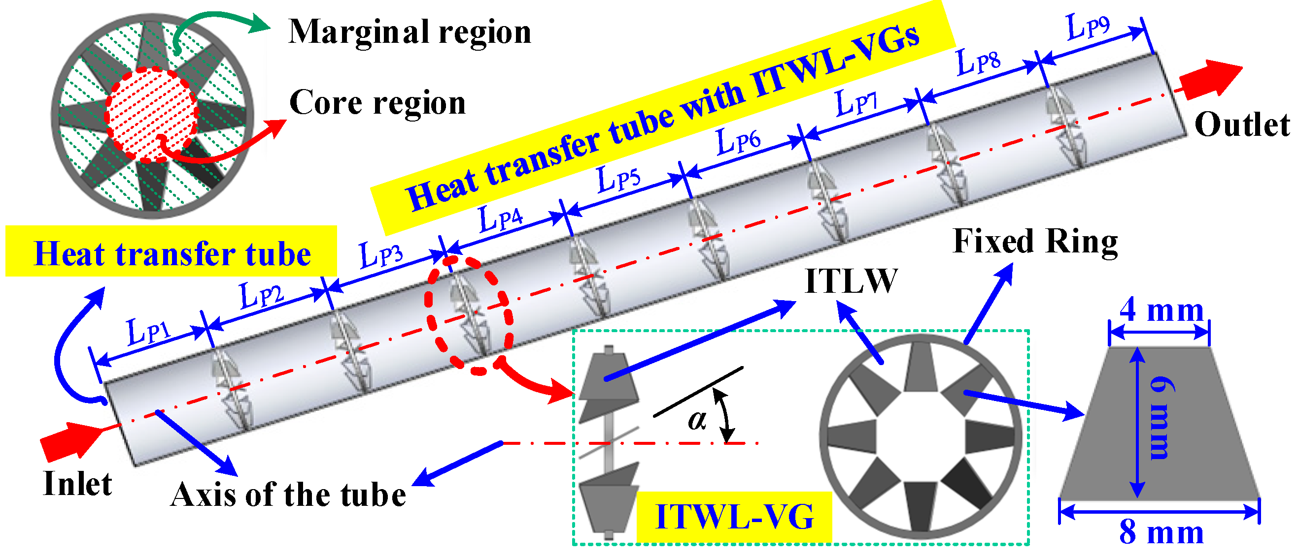
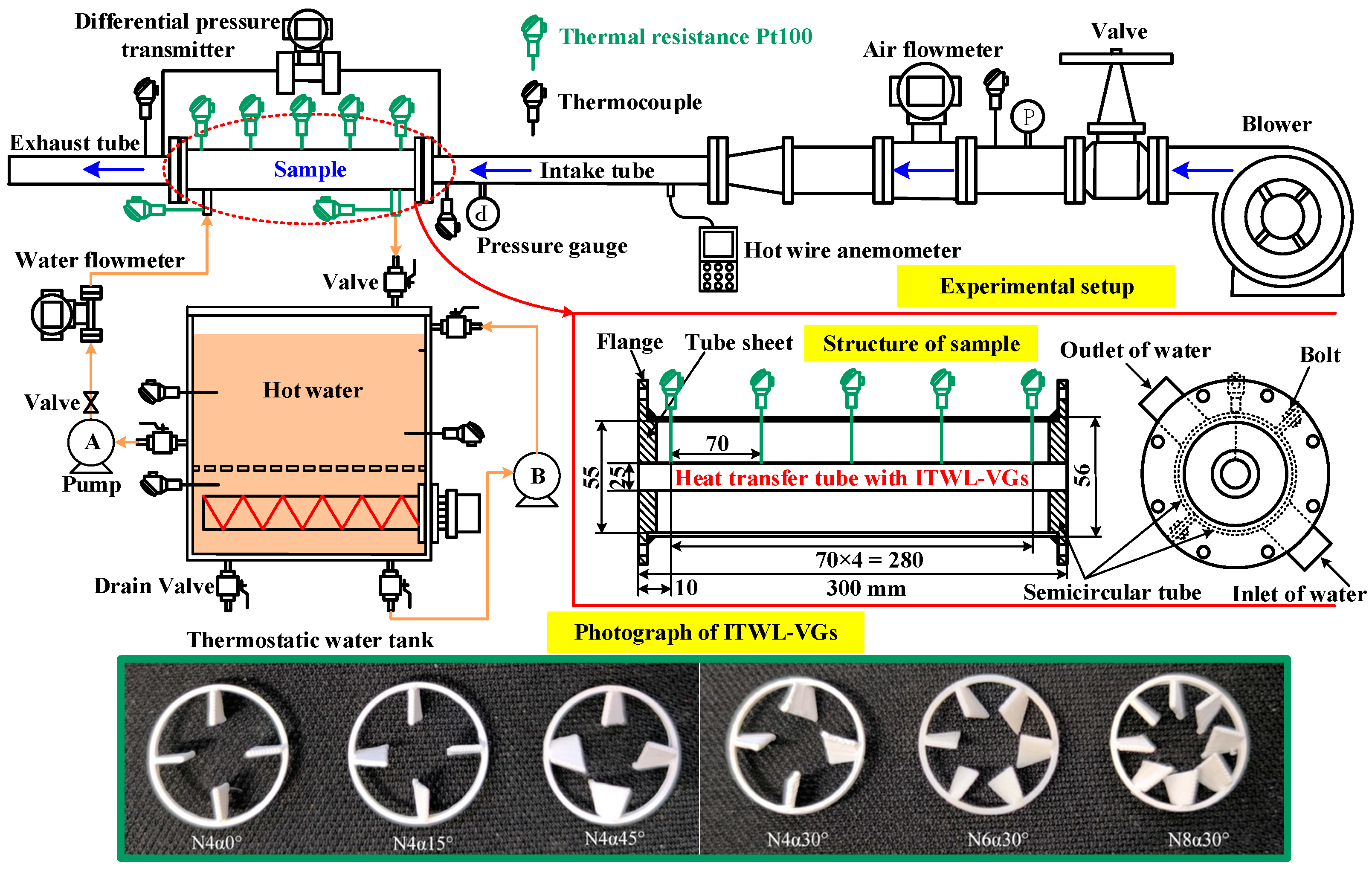
The ITWL-VG comprises a fixed ring with multiple uniformly distributed isosceles trapezoidal winglets (ITWs), as illustrated in Figure 1. The configuration parameters include (1) the ITW quantity (n = 4, 6, 8); (2) fixed ring dimensions (2 mm width × 1 mm thickness); and (3) angles of attack (α = 0°, 15°, 30°, 45°), with uniform α values within each ITWL-VG. Eight ITWL-VGs are installed in each heat exchange tube (300 mm length, 25 mm inner diameter, 0.5 mm wall thickness).
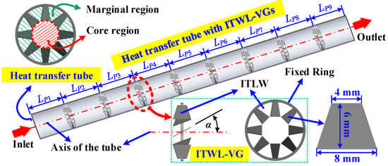
Figure 1.
The geometries and spatial arrangements for the ITWL-VGs.
The geometric configurations and spatial arrangements of the fabricated VGs are detailed in Figure 1 and Table 1. A systematic nomenclature is established for sample identification, where N4α30°-A2 denotes a configuration with four ITWs per VG at α = 30°, and eight ITWL-VGs are arranged in pattern A2.

Table 1.
The arrangement of the ITWL-VGs in a heat exchange tube (Unit: mm).
3. Numerical Study
3.1. Governing Equations
To simulate the heat transfer tube integrated with ITWL-VGs, the following assumptions are established based on the Reynolds number (Re) range of 5990–16,259: (1) the fluid in the circular heat transfer tube is a steady, Newtonian, fully developed, and incompressible turbulent flow; (2) the fluid has constant thermophysical properties; (3) convective heat transfer between the fluid and the solid, and heat conduction between the solids, are considered; (4) the effects of gravity, viscous heating, and thermal radiation are not considered. Based on the above assumptions, the mathematical expressions of the governing equation are as follows [37]:
Continuity equation:
Momentum equation:
Energy equation:
This study employs the SST k-ω turbulence model to analyze the heat transfer enhancement in heat transfer tubes with ITWL-VGs. The model’s capability to account for turbulent shear stress effects on the turbulent viscosity enables the accurate prediction of near-wall turbulence characteristics. Xu et al. [33] demonstrated the model’s superiority through a comparative analysis of five two-equation turbulence models (SST k-ω, standard k-ω, standard k-ε, RNG k-ε, and realizable k-ε) against Dittus–Boelter and Gnielinski correlations for a Nusselt number in smooth tubes, establishing SST k-ω as the most accurate predictor of turbulent flow with optimal computational efficiency. The SST k-ω model equations for k and ω are shown in Equations (4) and (5), respectively.
where Gk is the produced turbulent kinetic energy; Gω is the specific dissipation rate; Γk and Γω are defined as the effective diffusivity of k and ω, respectively; Yk and Yω denote the dissipation of k and ω due to turbulence, respectively. More details of the k and ω equations can be found in references [33,47].
3.2. Boundary Conditions
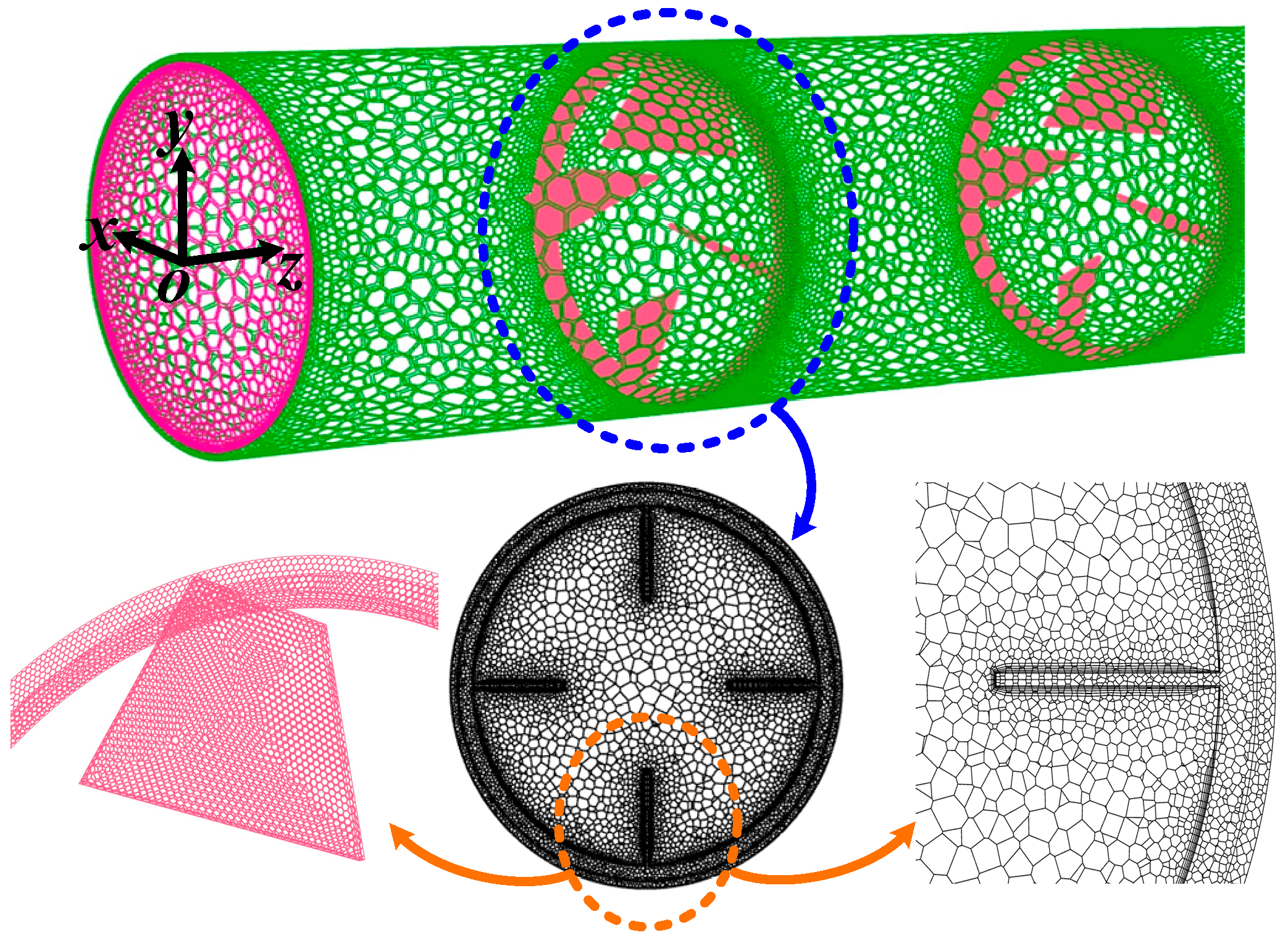
The computational domain of the heat transfer tube with ITWL-VGs was constructed using Pro/E Wildfire 5.0 software, with polyhedral meshing generated by ANSYS Mesh 18.0 (Figure 2).
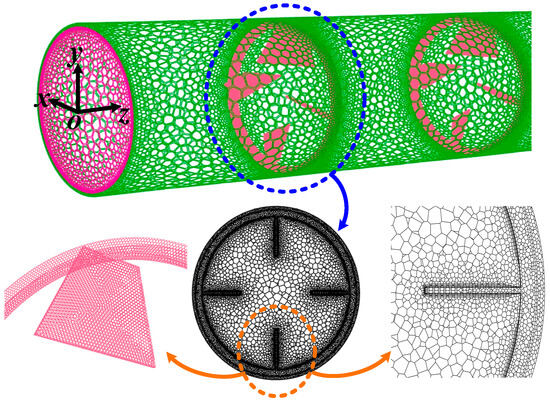
Figure 2.
The grids of the computational domain.
To accurately resolve near-wall phenomena, multi-layer boundary-layer grids were implemented at fluid–solid interfaces, maintaining y+ values below unity across all cases. The corresponding boundary conditions are specified as follows:
- (1)
- At the inlet:
ux = uy = 0; uz = Uinlet = 3.5 m/s, 4.7 m/s, 5.9 m/s, 7.1 m/s, 8.3 m/s; and 9.5 m/s, Tinlet = 298.15 K. Air was selected as the working fluid, with a reference temperature of 298.15 K. The experimental measurements showed a maximum inlet–outlet temperature difference of 14.3 K, corresponding to a less than 2% variation in thermophysical properties and justifying the assumption of constant properties in the simulations. The heat exchange tube and ITWL-VGs were fabricated from S30408 stainless steel (GB/T 14976-2012) [48] and nylon, respectively, and their thermophysical properties are detailed in Table 2. The turbulence intensity, calculated using the correlation (I = 0.16 Re−1/8) for fully developed flow, ranged from 4.76% to 5.39% across the investigated Reynolds numbers.
Table 2.
The thermophysical properties of the air, S30408, and nylon.
- (2)
- At the outlet:
The outlet of the heat transfer tube is exposed to the surrounding atmosphere. Hence, the boundary condition of zero-gradient was imposed.
- (3)
- At the external wall surface of the heat transfer tube:
A constant temperature of 328.15 K was imposed at the external surface of the heat transfer tube, TW = 328.15 K.
- (4)
- No-slip condition is applied at the walls of the ITWL-VGs and tube surface.
The governing equations were numerically solved using ANSYS Fluent 18.0 based on the finite volume method (FVM), with the solution convergence criteria set at 10−6 for the flow equations and 10−8 for the energy equations.
3.3. Validation of Grid Independence
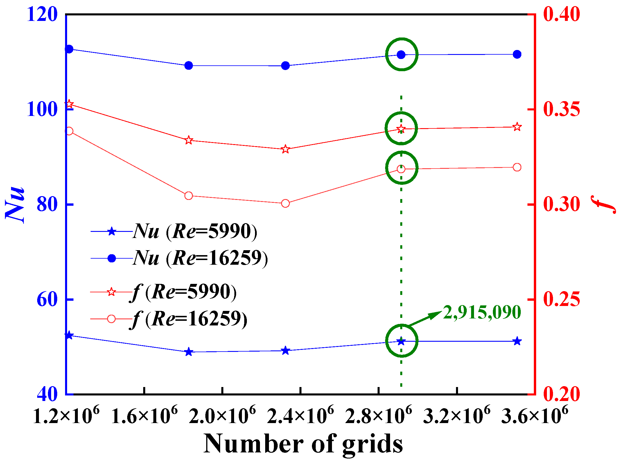
Grid independence validation was conducted to ensure numerical accuracy and eliminate grid size effects. The N8 α 30°-A2 configuration, representing the most complex geometry, was selected for this analysis. Numerical simulations were performed across five grid resolutions (1,215,746; 1,827,999; 2,323,366; 2,915,090; and 3,508,726) to evaluate the Nusselt number (Nu) and friction factor (f) at Re = 5990 (Uinlet = 3.5 m/s) and Re = 16,259 (Uinlet = 9.5 m/s), as shown in Figure 3.
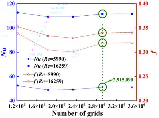
Figure 3.
Nu and f vs. number of grids for N8α30°-A2.
It was found that, with the increase in the number of grids, Nu and f first decrease rapidly, then increase, and finally tend to be flat and stable. When the number of grids increases from 2,915,090 to 3,508,726, the maximum deviations of Nu and f are 0.216% and 0.323%, respectively. It is indicated that a number of grids that is more than 2,915,090 is adequate for the present simulations. A similar method was used to determine the reasonable the numbers of grids for other models. Finally, the number of grids was set at slightly over 3 million for all the models.
4. Experimental Setup
4.1. Experiment Set and Sample
The experimental setup, illustrated in Figure 4, comprises two primary subsystems: the air handling system and the water circulation system. In the air handling system, ambient air is drawn through a centrifugal fan into the intake tube, subsequently passing through the test sample before being exhausted to the atmosphere. The air mass flow rate is precisely monitored using a calibrated mass flow meter and controlled via a precision regulating valve. A pressure gauge and a T-type thermocouple are installed upstream of the air mass flow meter for real-time measurement validation. The air velocity in the intake tube (air inlet velocity) is measured by a hot-wire anemometer. The air velocity (air inlet velocity) calculated by both the mass flowmeter and the geometrical parameters of the intake tube is compared with the reading of the hot-wire anemometer, and the deviation between the two must be less than 1%. There are five air inlet velocities, namely 3.5 m/s, 4.7 m/s, 5.9 m/s, 7.1 m/s, 8.3 m/s, and 9.5 m/s. The data recorded by the pressure gauge upstream of the sample provide a basis for setting the inlet pressure of the sample during the numerical simulation process. Thermal characterization is achieved through positioned T-type thermocouples both upstream and downstream of the sample, enabling precise measurement of the inlet and outlet air temperatures. Furthermore, a differential pressure transmitter is implemented to quantify the air pressure difference through the test sample.
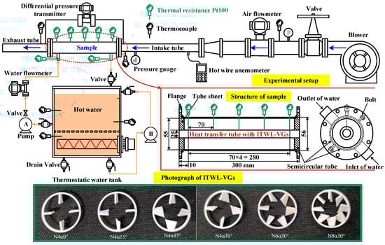
Figure 4.
Experiment set and sample.
The water circulation subsystem employs a precision thermostatic water tank maintained at 328.15 K by an integrated heating system, temperature control unit, and recirculation loop driven by pump B. The hot water is circulated through the test sample via pump A, facilitating heat exchange with the air before returning to the thermostatic water tank. The water flow rate is precisely regulated using a calibrated volumetric flow meter and control valve assembly. To establish constant wall temperature boundary conditions at the heat exchange tube’s outer surface, the water flow rate is maintained at 1 m3/h, significantly exceeding the thermal load requirements. Temperature monitoring at the sample’s water inlet and outlet is achieved using Pt100 thermal resistance (Chongqing Chuanyi Automation Co., Ltd., Chongqing, China). The substantial flow rate ensures a minimal thermal gradient, with the measured temperature differentials being consistently below 0.2 K throughout the experimental trials. All thermal components, including the test sample, thermostatic water tank, and hot water inlet and outlet pipelines, are comprehensively covered with insulation materials to minimize heat losses. This insulation strategy ensures accurate thermal measurements by reducing the environmental heat transfer to negligible levels.
The test sample comprises a heat exchange tube with eight ITWL-VGs, two semicircular containment shells, tube sheets, five Pt100 thermal resistances, and associated fastening components, all of which forms a fundamental shell-and-tube heat exchanger. The thermal system is designed to exert countercurrent flow: air circulates through the enhanced tube side (equipped with ITWL-VGs), while the hot water flows through the annular shell side formed between the primary heat exchange tube and semicircular containment shells, facilitating efficient inter-fluid heat transfer. For thermal monitoring, five Pt100 thermal resistances are axially distributed at equidistant intervals along the heat exchange tube’s external surface. The substantial shell-side flow rate ensures near-isothermal conditions at the outer surface of the heat exchange tube, a methodology previously validated in the research team’s earlier investigations [11]. The tube-side enhancement features eight uniformly configured ITWL-VGs, which are serially arranged and fixed using steel wires, consistent with the methodologies established in [33,47].
The temperature measurement system incorporates two precision instruments: a type T thermocouple (WRCK, Copper-Constantan) and PT100 thermal resistances (WZPK, Class A), both manufactured by Chongqing Chuanyi Automation Co., Ltd. (Chongqing, China). The type T thermocouple exhibits an operational temperature range from −40 °C to 350 °C, with an implemented measurement range of 25–50 °C in the current application. Its measurement accuracy is characterized by a maximum permissible deviation of ±0.0075 t. The PT100 thermal resistances, classified as Class A according to international standards, demonstrate a broader operational range from −200 °C to 500 °C, while they were utilized within the 25–100 °C range in this specific application. The instrument maintains a superior accuracy level with a maximum positive deviation of +0.002 t. The fluid measurement system comprises two high-precision instruments: VY-series vortex flowmeters and an EJX-A series differential pressure transmitter, both manufactured by Yokogawa China Co., Ltd. (Shanghai, China). All thermocouples that were employed for temperature measurements underwent rigorous calibration against reference standard thermocouples in a tube furnace across multiple temperature points spanning their operational range. This calibration process yielded characteristic curves and correction factors for subsequent measurement adjustments. The specified accuracies of both the flowmeters and differential pressure transmitters were validated and certified by the manufacturer. All measuring devices were adjusted before the experiment to ensure accuracy and stability. The sampling period of the data acquisition device, which was used to record the flow rate, temperature, and pressure drop of the air and hot water, was 1 s.
4.2. Uncertainty Analysis
Uncertainty analysis can quantify the uncertainty of measurement results and provide a clear quantitative index for the reliability of measurement results. The measurement uncertainties of the parameters in this study are presented in Table 3. The uncertainties of Nu, f, and Re were evaluated following the methodology described in [43,44,49], with these parameters being calculated as follows:
where Nu is the Nusselt number; h is the heat transfer coefficient; Di is the inner diameter of the heat exchange tube; Qair is the air heat transfer rate; L is the tube length; ∆Tm is the mean temperature difference; Tinlet,air and Toutlet,air are the air temperatures at the inlet and outlet; f is the friction factor; ∆P is the pressure drop.
Table 3.
The maximum relative uncertainties of the experiment.
In addition, the energy balance was calculated according to the correlation of (Qair − Qwater)/Qave, where Qave = (Qair + Qwater)/2; Qair and Qwater are the heat transfer rates of the air and the hot water, respectively. The value of (Qair − Qwater)/Qave ranged from 0.8% to 1.7%. This means that the data obtained during the experiment are valid. Through the above analysis, the calculation of the heat transfer rate is only based on the air (Qair) in order to simplify subsequent calculations.
5. Data Reduction
To evaluate the flow and heat transfer of the heat transfer tube with ITWL-VGs, some important parameters were considered:
The Reynolds number is calculated as:
where ρair and µair are the density and viscosity of the air, respectively.
The heat transfer coefficient is calculated as:
where cp,air is the air-specific heat; mair is the air mass flow rate; A is the heat transfer area of the heat exchange tube.
The mean temperature difference is calculated as:
The Nusselt number is determined by the following equation:
The friction factor is determined by the following equation:
The thermal enhancement factor is as follows:
where Nuref,0 and fref,0 are the Nusselt number and friction factor of the smooth tube, respectively.
6. Results and Discussion
6.1. Validation of Numerical Results and Experiment Data
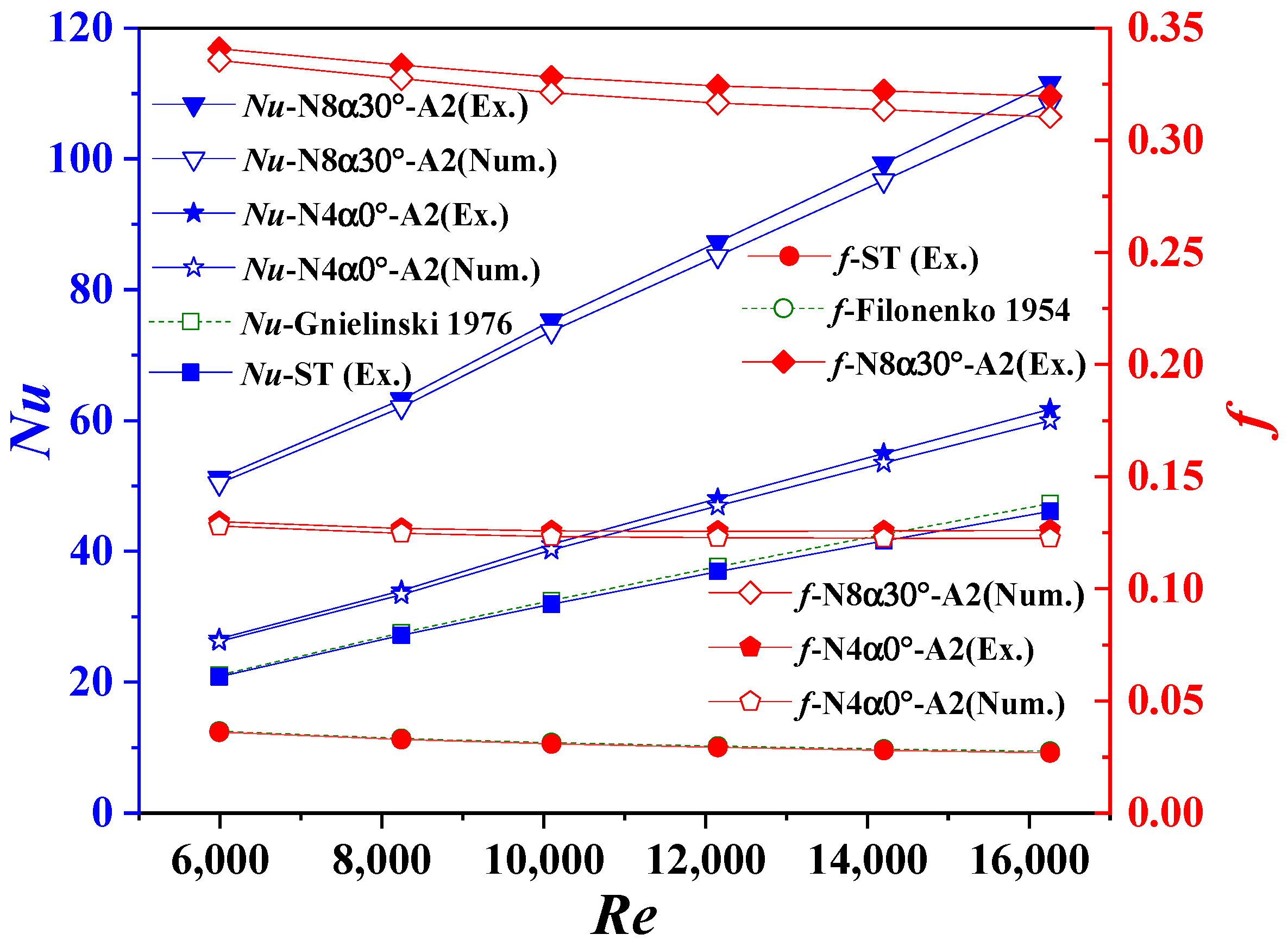
The experimental system was validated by comparing the Nu and f of the smooth tube (ST) with the established correlations from Filonenko [50] and Gnielinski [51], respectively.
The work of Filonenko for f:
The work of Gnielinski for Nu:
As shown in Figure 5, the maximum deviations between the experimental and theoretical values are 2.57% for Nu and 2.49% for f, demonstrating excellent agreement. This close correlation confirms the reliability of the experimental system for subsequent investigations. All data presented in this study were obtained through experimental measurements. Numerical simulations incorporating multiple physical fields were conducted to analyze the heat transfer enhancement mechanism of the given system. To validate the numerical approach, two representative models with minimum and maximum grid numbers (N4α0°-A2 and N8α30°-A2) were selected for comparative analysis. As illustrated in Figure 5, the numerical predictions of Nu and f show excellent agreement with the experimental data, with maximum deviations of 3.05% and 2.98%, respectively, confirming the reliability of the simulation methodology.
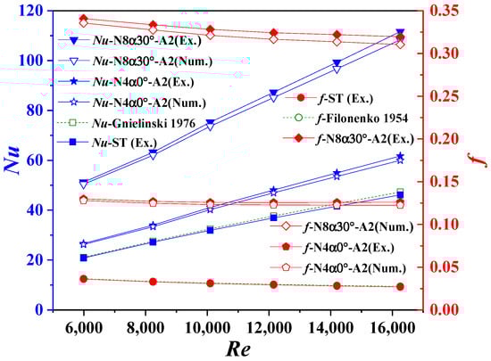
Figure 5.
Comparison of experiment data with theoretical values and numerical results [42].
The observed discrepancy, where the experimental data exceed the numerical results, can be attributed to the presence of 0.4 mm diameter steel wires used to fix the ITWL-VGs in the heat transfer tube. These 300 mm long wires, while not incorporated in the numerical model, likely induce additional flow disturbance, consequently enhancing the heat transfer and increasing the pressure drop beyond the simulated predictions.
6.2. The Effect of the Number of ITWs
For comprehensive analysis of the flow and heat transfer characteristics, the tube cross-section was divided into two distinct regions (Figure 1): (1) the core region, characterized by a minimal influence of the ITWL-VG and located at the tube center, and (2) the marginal region, exhibiting significant ITWL-VG effects and occupying the peripheral area.
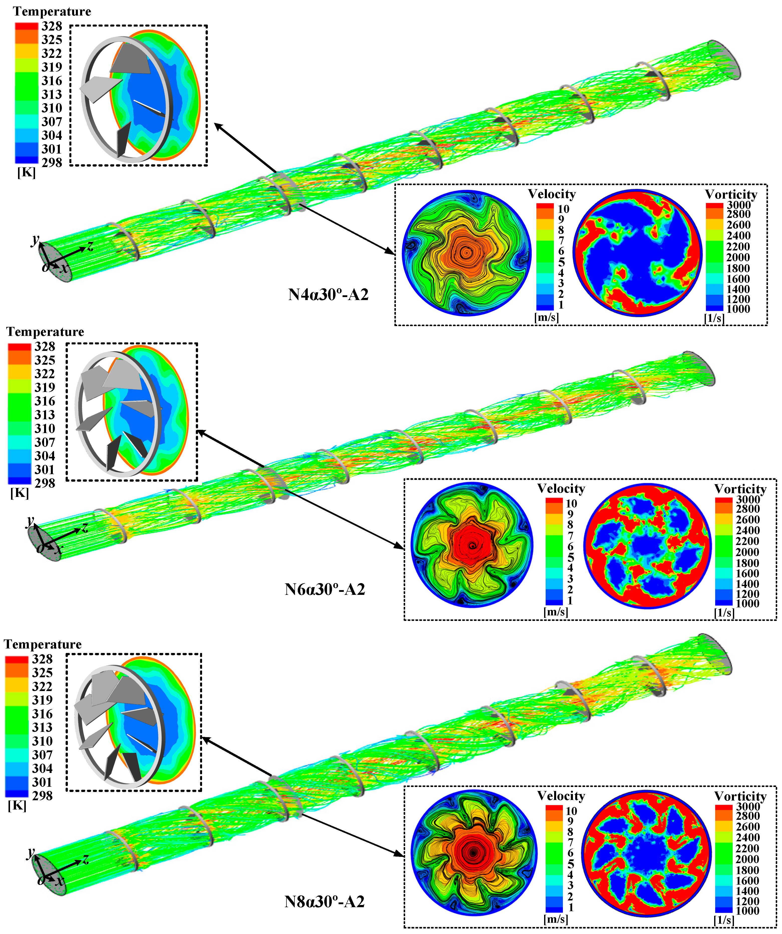
Figure 6 presents the temperature fields, velocity profiles, streamlines, and vorticity distributions for N4α30°-A2, N6α30°-A2, and N8α30°-A2 at plane z = 110 mm (Re = 10,098). The complex streamline patterns surrounding the ITWL-VGs suggest significant flow phenomena, including flow impingement, separation, and circumvention. Notably, the ITWL-VGs induced substantial flow redirection, generating multiple longitudinal vortices downstream. The vortex count exhibits a direct correlation with the number of ITWs. Longitudinal vortex formation is characterized by a reduced axial velocity within the vortex core and accelerated flow in the peripheral regions. Conversely, the vorticity magnitude demonstrates an inverse distribution, with peak values concentrated in the vortex cores and diminished values in the surrounding areas.
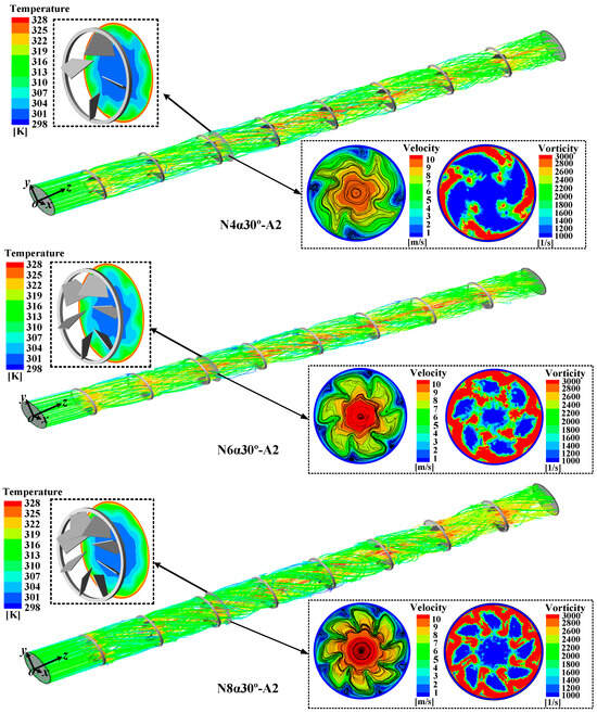
Figure 6.
Temperature distributions, velocity distributions, streamline, and vorticity of N4α30°-A2, N6α30°-A2, and N8α30°-A2 at plane z = 110 mm with Re = 10,098.
This phenomenon fundamentally results from flow redirection induced by the ITWL-VGs, where partial airflow deviates from the mainstream toward the tube wall. The ITWs generate two distinct flow components: a wall-ward secondary flow and a core-ward secondary flow. The wall-ward flow enhances the heat transfer by directing cooler fluid toward the heated wall, effectively thinning the thermal boundary layer. Simultaneously, the core-ward flow transports heated fluid from the wall region to the tube center, elevating the core temperature. This interaction promotes intensive fluid mixing in the marginal region, creating a more uniform temperature distribution with a higher thermal intensity compared to the core region, thereby significantly improving the overall heat transfer efficiency. Furthermore, the periodic airflow through the ITWL-VGs creates distinct flow resistance characteristics that are significantly higher in the marginal region than in the core region. Consequently, the velocity profile demonstrates a marked reduction in the marginal region, with this velocity gradient intensifying in proximity to the ITWL-VGs.
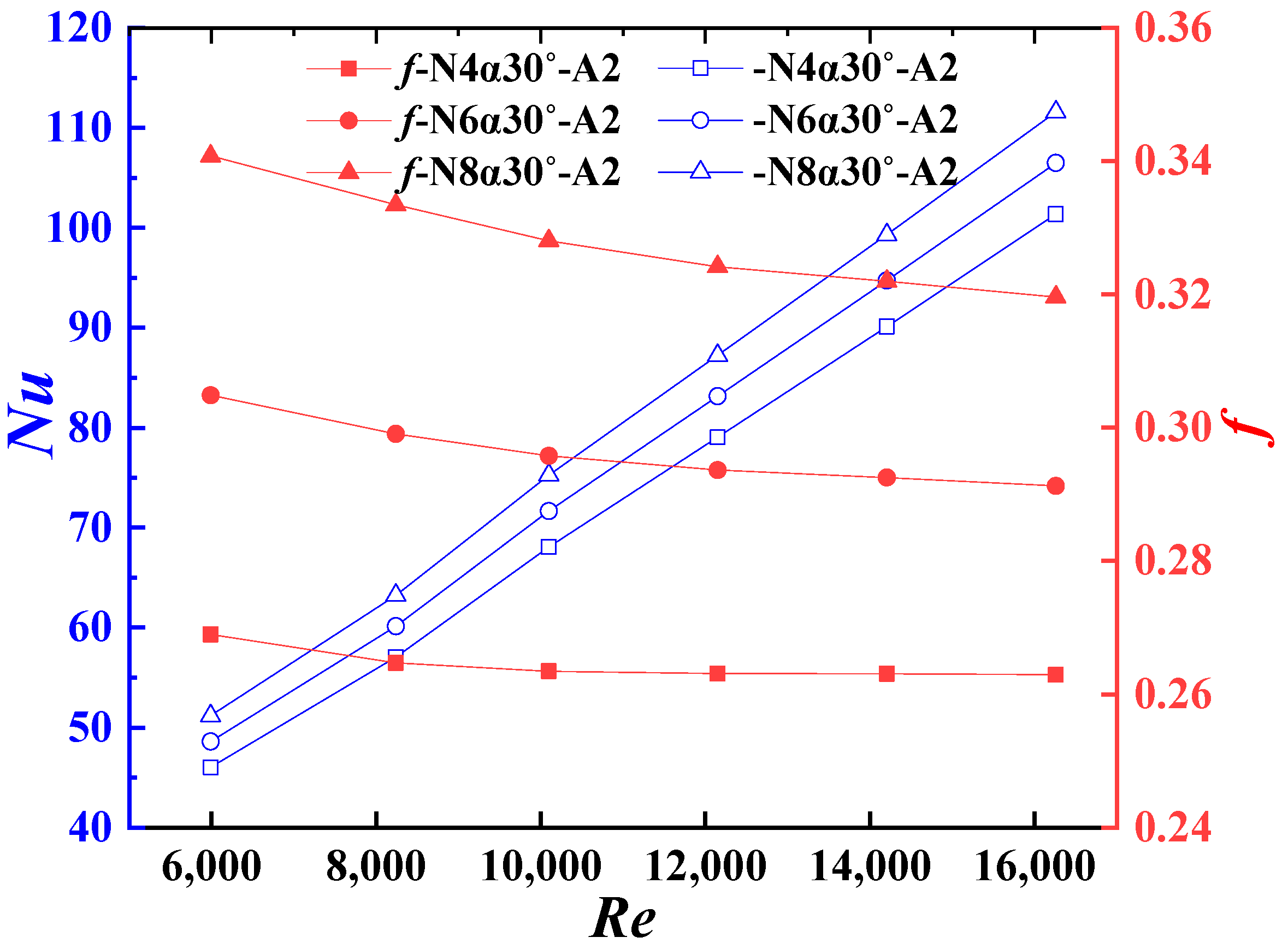
Figure 6 reveals that increasing the ITW number (N) enhances the longitudinal vortex generation downstream of the ITWL-VGs, intensifying the fluid mixing and heat transfer in the marginal region. This leads to elevated temperatures in both the marginal and core regions due to enhanced core-ward flow. However, the concomitant increase in flow resistance significantly reduces the marginal region’s velocity relative to the core region. These observations are corroborated by Figure 7, which presents the experimental Nu and f for N4α30°-A2, N6α30°-A2, and N8α30°-A2. The data demonstrate that Nu increases with both the Re and ITW numbers, while f exhibits an inverse relationship with Re but increases with the ITW number. Specifically, N6α30°-A2 and N8α30°-A2 show Nu enhancements of 5.1–5.7% and 10.1–11.3%, respectively, relative to N4α30°-A2. Correspondingly, their f values increase by 10.8–13.6% and 21.4–26.8%.
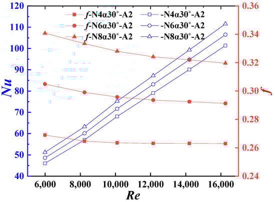
Figure 7.
Experimental Nu and f of N4α30°-A2, N6α30°-A2, and N8α30°-A2.
6.3. The Effect of the Angle of Attack
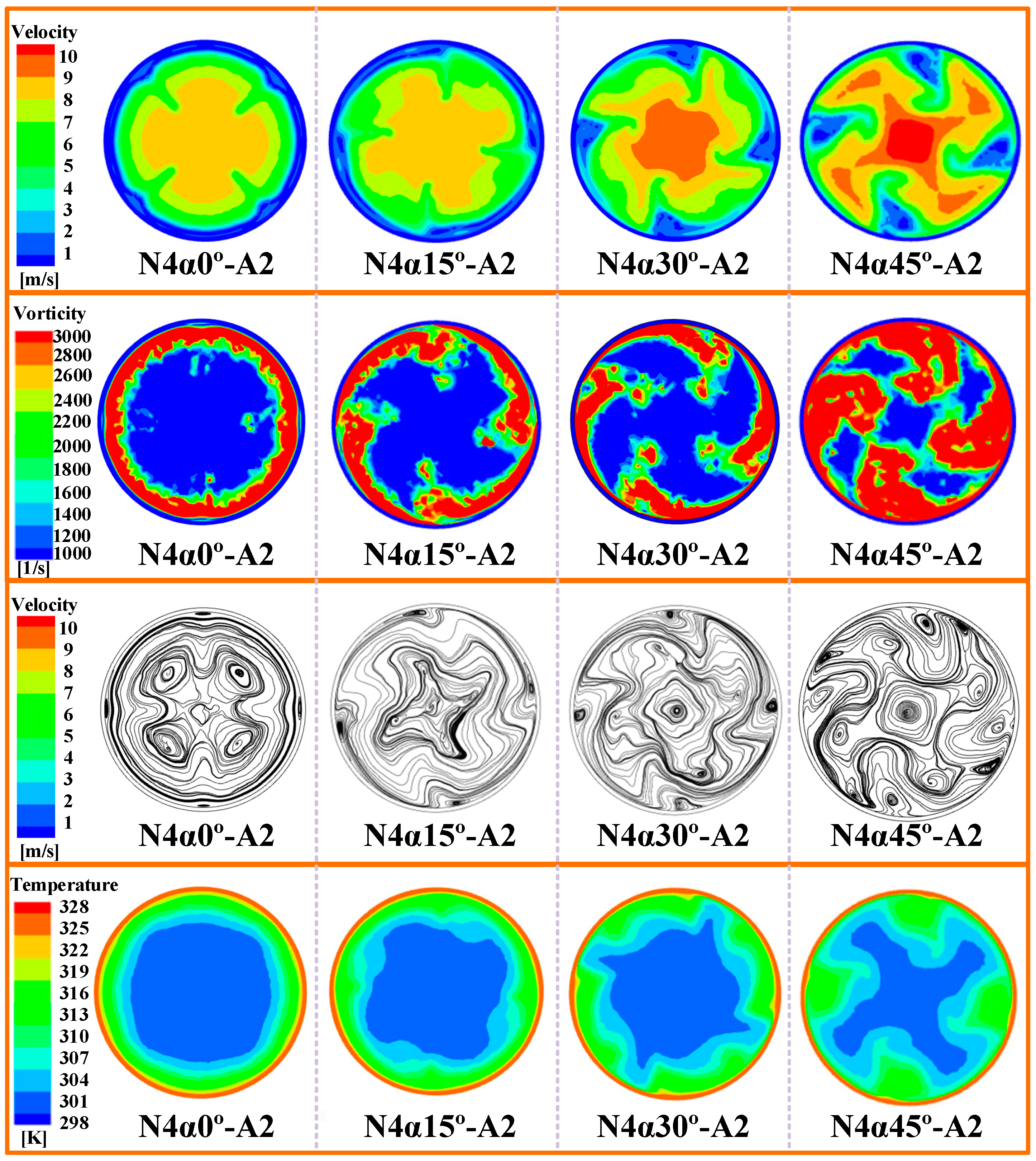
Figure 8 illustrates the velocity, vorticity, streamline, and temperature distributions for N4α0°-A2, N4α15°-A2, N4α30°-A2, and N4α45°-A2 at plane z = 110 mm (Re = 10,098). Notably, the ITWL-VG in N4α0°-A2 exhibits minimal functional effectiveness at an angle of attack of zero (α = 0°), failing to generate downstream longitudinal vortices. Consequently, the fluid mixing and heat transfer in the marginal region remain limited. Significant vorticity and temperature gradients are confined to the near-wall region, while the core region maintains weak thermal exchange characteristics. This configuration results in a disproportionately large core region dominated by cooler air relative to the heated marginal region. Conversely, the flow resistance remains minimal at α = 0°, exhibiting velocity distribution characteristics that are similar to those in smooth tubes. However, the velocity profile demonstrates distinct concave deformations at ITW locations, where it deviates from the typical concentric pattern. Quantitative analysis reveals a marginally higher average velocity in the core region compared to the marginal region.
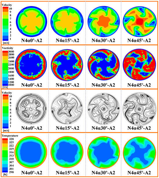
Figure 8.
The velocity, vorticity, streamline, and temperature distribution of N4α0°-A2, N4α15°-A2, N4α30°-A2, and N4α45°-A2 at plane z = 110 mm with Re = 10,098.
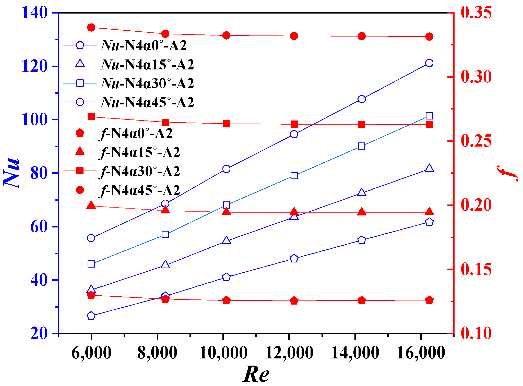
Increasing the angle of attack (α) promotes longitudinal vortex generation downstream of the ITWL-VGs, with both the intensity and spatial extent exhibiting progressive enhancement. This development intensifies the fluid mixing in the marginal region, significantly improving the heat transfer efficiency. Concurrently, the strengthened core-ward flow facilitates thermal exchange between the heated marginal flow and the cooler core region. The thermal enhancement manifests as substantial temperature elevation in the marginal region and corresponding compression of the cooler core region. Furthermore, elevated α values increase the flow resistance and vortex strength in the marginal region, resulting in reduced local velocities, while the core region experiences marked velocity augmentation. Figure 9 further substantiates these observations, presenting experimental Nu and f data for N4α0°-A2 through N4α45°-A2. The results demonstrate a positive correlation between the Nu and both the Re and α, while the f exhibits an inverse relationship with the Re but increases with the α. Quantitative analysis reveals that N4α15°-A2, N4α30°-A2, and N4α45°-A2 achieve average Nu enhancements of 33.1%, 67.5%, and 99.8%, respectively, relative to N4α0°-A2. Correspondingly, their f values increase by 54.3%, 109.7%, and 163.2%. These findings confirm that the heat transfer enhancement becomes progressively more pronounced with an increasing α.
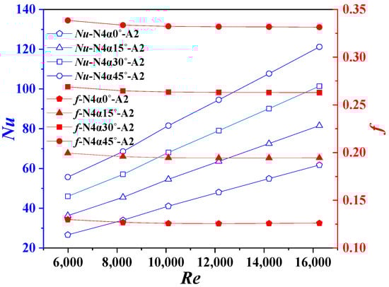
Figure 9.
Experimental Nu and f of N4α0°-A2, N4α15°-A2, N4α30°-A2, and N4α45°-A2.
6.4. The Effect of the Arrangement of the ITWL-VGs
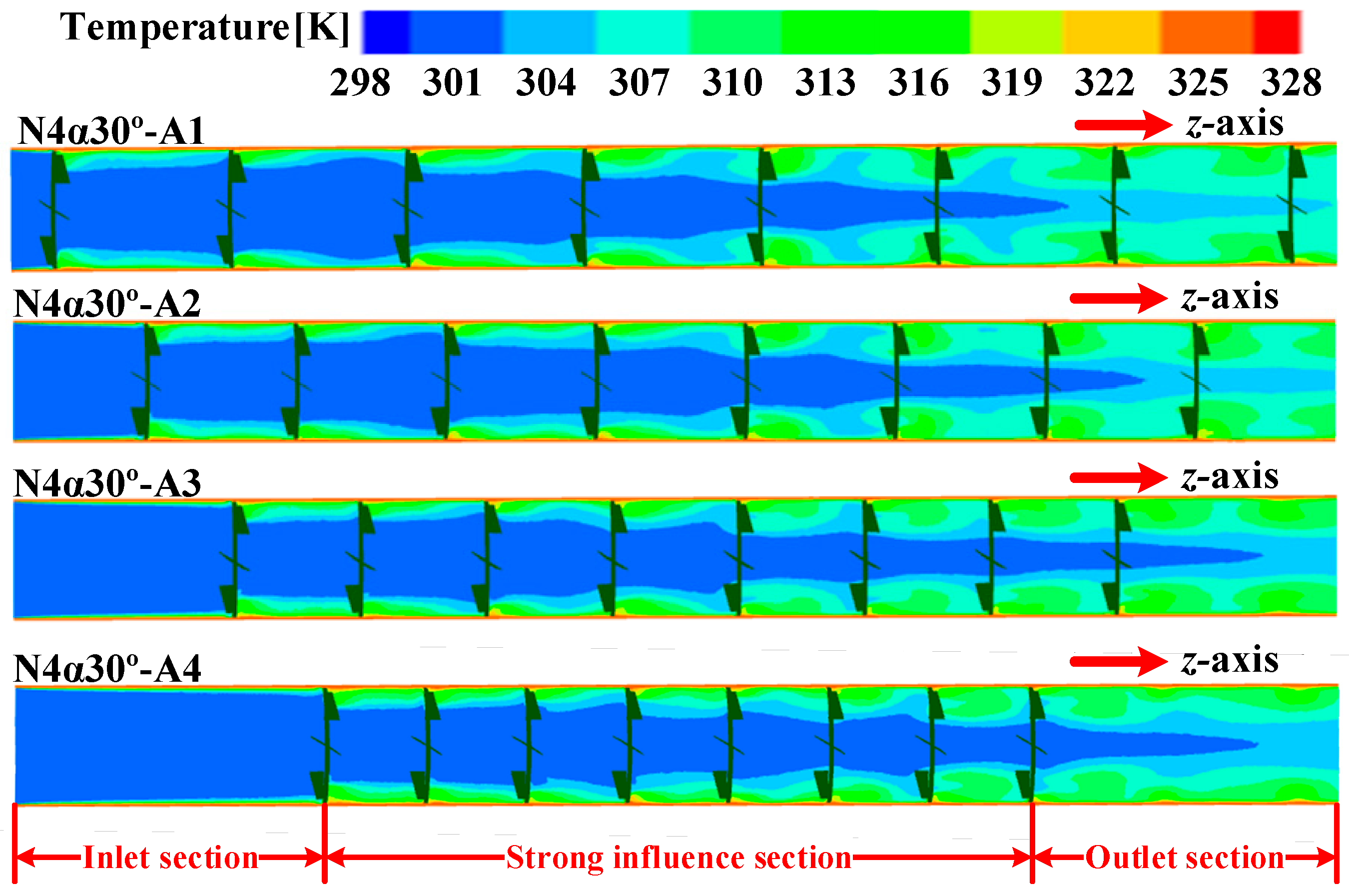
Figure 10 illustrates the longitudinal temperature distribution for N4α30°-A1 through N4α30°-A4 at Re = 10,098. For analytical clarity, the tube is divided into three distinct regions: (1) the inlet section (LP1), extending from the inlet to the first ITWL-VG; (2) the strong influence section (LP2–LP8), spanning between the first and eighth ITWL-VGs; and (3) the outlet section (LP9), extending from the eighth ITWL-VG to the outlet. The specific dimensions and definitions of LP1–LP9 are provided in Figure 1 and Table 1.

Figure 10.
Longitudinal sectional temperature distribution of N4α30°-A1, N4α30°-A2, N4α30°-A3, and N4α30°-A4 with Re = 10,098.
The analysis reveals distinct thermal characteristics across different sections: (1) In the inlet section (LP1), the absence of ITWL-VGs allows the rapid formation of a flow boundary layer along the tube wall. This layer progressively thickens axially, increasing the thermal resistance and limiting the heat exchange to the near-wall region, while the core region remains thermally inactive. (2) Within the strong influence section (LP2–LP8), the sequential interaction of the airflow with multiple ITWL-VGs generates longitudinal vortices downstream of each VG. These vortices disrupt boundary layer development, reduce the thermal resistance, and enhance the wall-to-fluid heat transfer. Simultaneously, the intensified mixing of cold and hot fluids in the marginal region significantly improves the inter-fluid heat transfer, resulting in a pronounced temperature gradient between the marginal and core regions. Therefore, the average temperature of the air in the marginal region becomes significantly higher than that in the core region. Furthermore, the core-ward flow facilitates thermal mixing between the heated marginal region and the cooler core region, significantly elevating the core temperature while progressively reducing the cooler core volume, which eventually becomes negligible. This phenomenon underscores the section’s exceptional heat transfer enhancement and optimal utilization of ITWL-VG functionality. (3) In the outlet section (LP9), residual heat transfer enhancement persists near the eighth ITWL-VG. However, the longitudinal vortices exhibit limited sustainability, with their intensity decaying downstream. In the absence of additional ITWL-VGs, the vortex generation ceases, leading to gradual dissipation of the enhanced heat transfer effect until complete its attenuation.
Under fixed tube length and ITWL-VG count conditions, three critical observations emerge: (I) In the strong influence section, reduced ITWL-VG spacing (LP) intensifies the marginal-region heat transfer but minimally affects the core region. This occurs because decreased LP enhances the flow disturbance, causing overlapping longitudinal vortices that amplify the vortex intensity. Consequently, while the marginal-region heat transfer improves significantly, increased flow resistance redirects airflow to the core region, elevating the core velocity but reducing the thermal mixing efficiency. (II) The reduced LP shortens the strong influence section, necessitating longer inlet and outlet sections. This configuration diminishes the overall heat transfer enhancement, suggesting that uniform ITWL-VG distribution optimizes the thermal performance. (III) While references [39,44,45] report an improved heat transfer with a reduced LP, their experimental conditions differ fundamentally: their tube length was fixed but their VG count was variable. In contrast, this study fixes both parameters, revealing an inverse relationship. This discrepancy suggests the existence of an optimal VG spacing that is dependent on the VG geometry and fluid state parameters, rather than a simple monotonic trend.
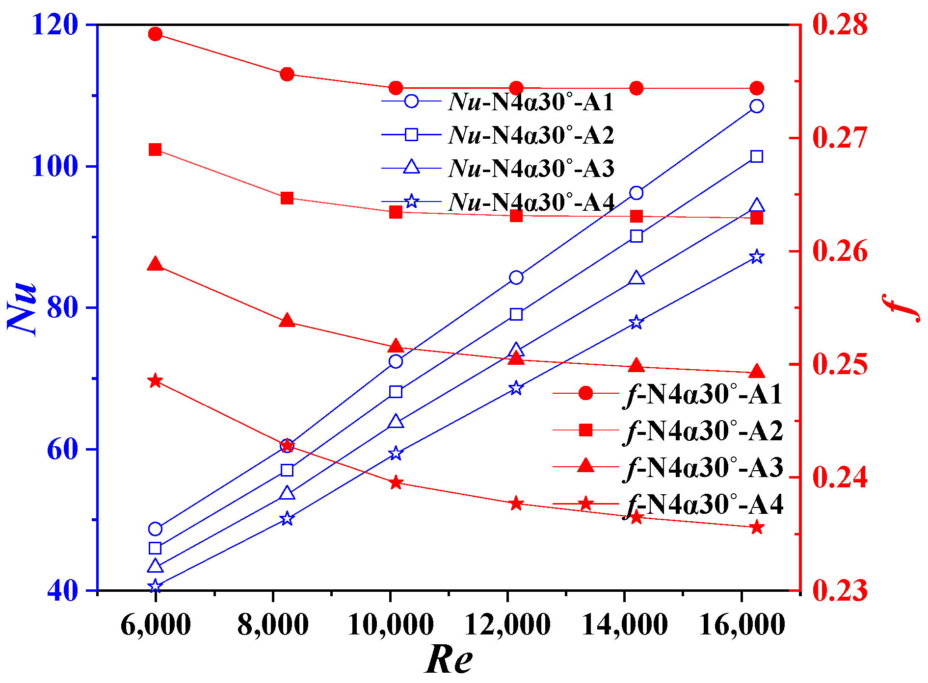
Figure 11 presents the experimental Nu and f for N4α30°-A1, N4α30°-A2, N4α30°-A3, and N4α30°-A4. The results demonstrate that the Nu increases with the Re but decreases with the f. Additionally, both the Nu and f exhibit positive correlations with the LP. Specifically, N4α30°-A1, N4α30°-A2, and N4α30°-A3 show average Nu enhancements of 7.3%, 14.9%, and 22.4%, respectively, compared to N4α30°-A4. Correspondingly, their f values increase by 5.0%, 10.3%, and 14.7%. These findings, consistent with Figure 10, confirm that uniform ITWL-VG distribution optimizes the thermal performance.
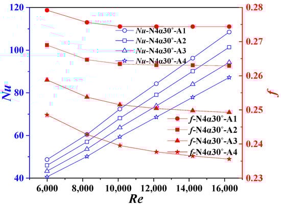
Figure 11.
Experimental Nu and f of N4α30°-A1, N4α30°-A2, N4α30°-A3, and N4α30°-A4.
6.5. Comprehensive Performance
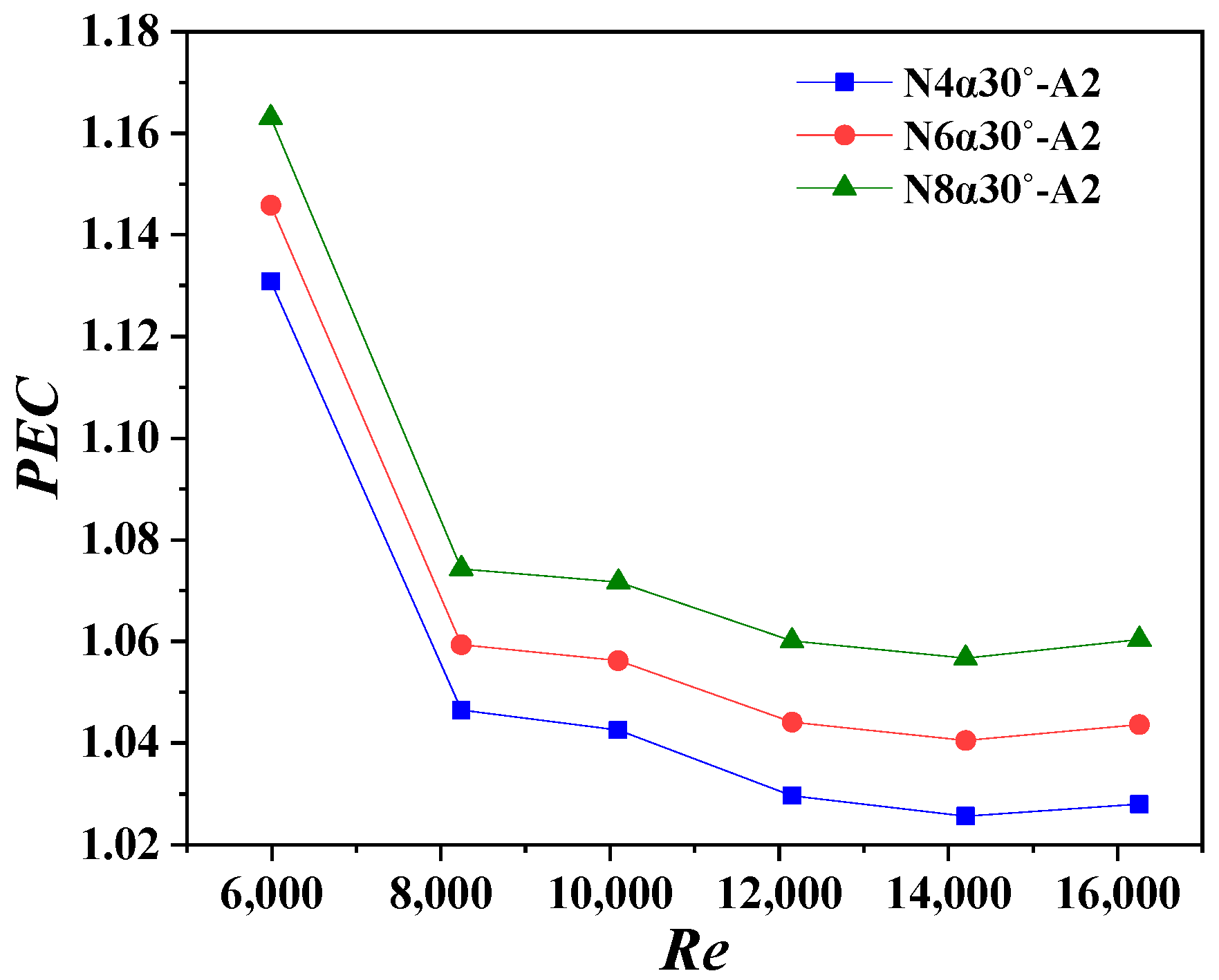
Figure 12 illustrates the PEC variation with Re for N4α30°-A2, N6α30°-A2, and N8α30°-A2. The PEC values exhibit a rapid decline for Re < 8241, followed by a gradual decrease at higher Re values. All configurations demonstrate PEC values that exceed unity, ranging from 1.03 to 1.16. These results indicate that uniformly distributed ITWL-VGs with optimal α values significantly enhance the PEC, with the performance improving as the number of ITWs (N) increases. Notably, N4α30°-A2, N6α30°-A2, and N8α30°-A2 all achieve substantial heat transfer enhancement.
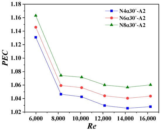
Figure 12.
The PEC vs. the Re for N4α30°-A2, N6α30°-A2, and N8α30°-A2.
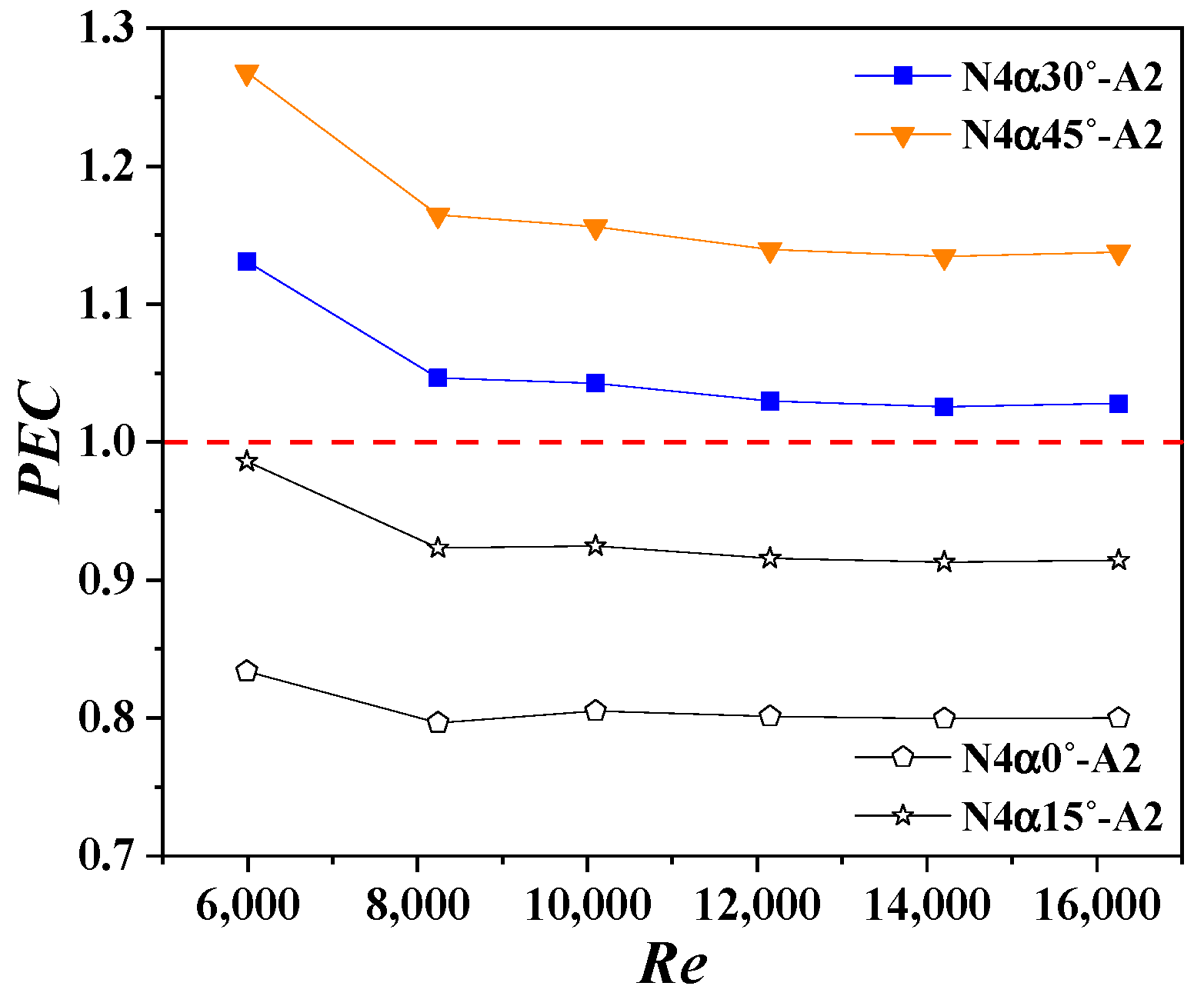
Figure 13 presents the PEC variation with the Re for N4α0°-A2, N4α15°-A2, N4α30°-A2, and N4α45°-A2. The results demonstrate a positive correlation between the PEC and α, with N4α30°-A2 and N4α45°-A2 exceeding unity (maximum PEC = 1.27 for N4α45°-A2), while N4α0°-A2 and N4α15°-A2 remain below unity. This indicates that α ≥ 30° is necessary for effective heat transfer enhancement, as larger angles promote longitudinal vortex formation and significantly improve the PEC. Within the investigated parameter range, α values below 30° prove ineffective for thermal performance enhancement.
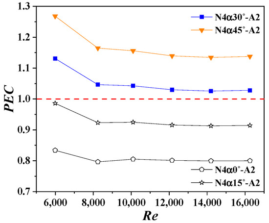
Figure 13.
The PEC vs. the Re for N4α0°-A2, N4α15°-A2, N4α30°-A2, and N4α45°-A2.
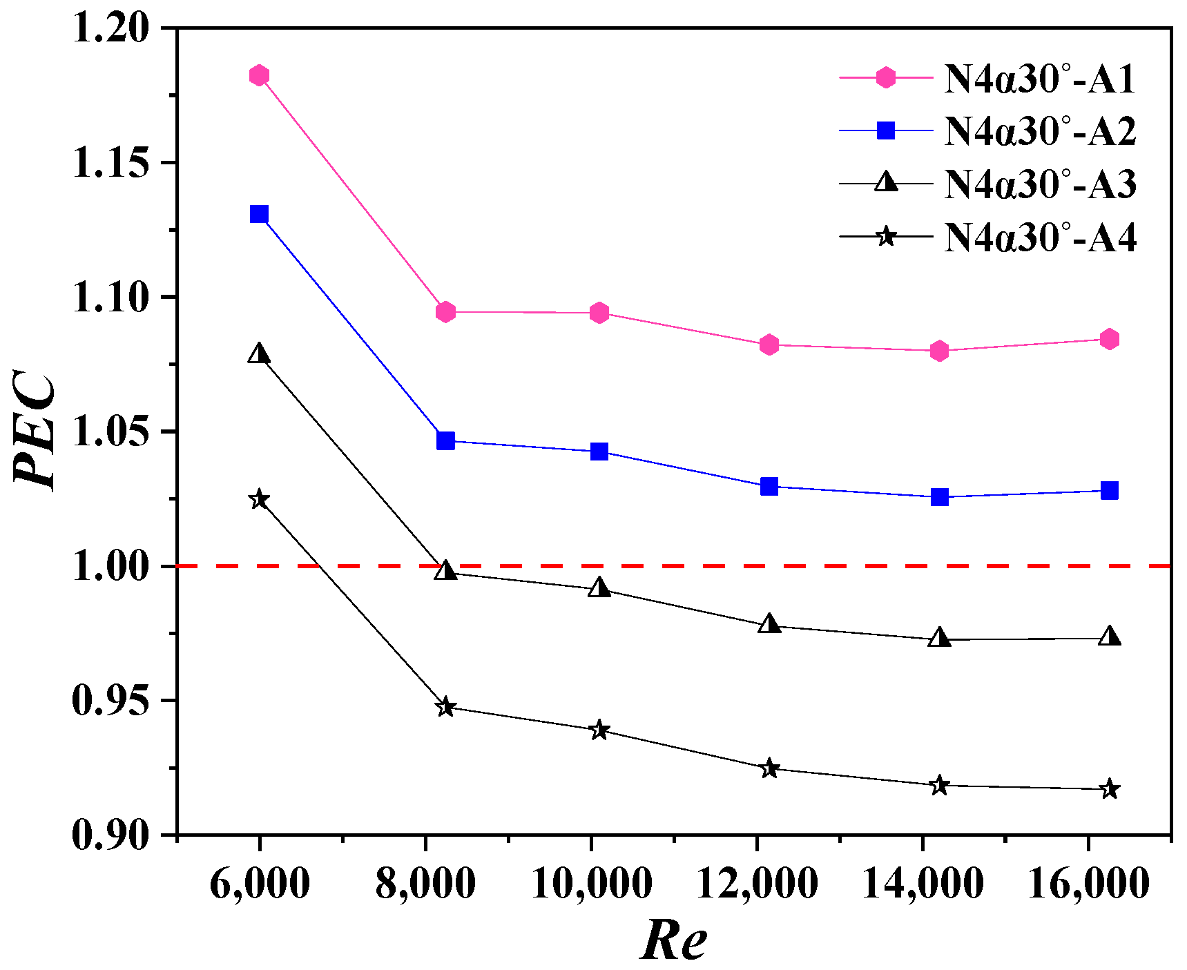
Figure 14 shows the PEC variation with the Re for N4α30°-A1, N4α30°-A2, N4α30°-A3, and N4α30°-A4. The results demonstrate an inverse relationship between the PEC and Re, and a positive correlation with LP. Notably, N4α30°-A1 and N4α30°-A2 maintain PEC > 1 (maximum = 1.18 for N4α30°-A1), whereas N4α30°-A3 and N4α30°-A4 fall below unity at Re > 8241. This suggests that, when the LP decreases below a critical threshold under a fixed tube length and ITWL-VG count, the dense VG arrangement reduces the effective strong-influence section length. Consequently, the extended inlet and outlet sections, characterized by weak heat transfer enhancement, diminish the overall thermal performance. While larger LP values enhance the heat transfer within the current study’s constraints, an excessive LP would, conversely, degrade the performance, as confirmed by references [39,44,45]. These findings indicate the existence of an optimal LP value for maximizing thermal enhancement.
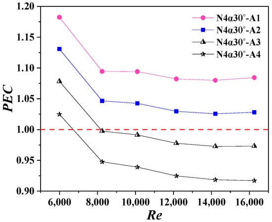
Figure 14.
The PEC vs. the Re for N4α30°-A1, N4α30°-A2, N4α30°-A3, and N4α30°-A4.
7. Conclusions
This study investigates the thermal performance of circular heat transfer tubes equipped with isosceles trapezoidal winglet longitudinal vortex generators (ITWL-VGs) through experimental and numerical analyses. The effects of the α, N, and VG arrangement on the Nu, f, and PEC are systematically examined, with heat transfer enhancement mechanisms being elucidated through multi-physical field analysis. Key findings include:
- (1)
- Uniformly arranged ITWL-VGs with an optimal α demonstrate an enhanced thermal performance with an increasing N, as additional longitudinal vortices downstream of the VGs intensify fluid mixing. This phenomenon significantly improves the PEC, with N4α30°-A2, N6α30°-A2, and N8α30°-A2 exhibiting particularly notable heat transfer enhancement;
- (2)
- The Nu, f, and PEC exhibit positive correlations with α. The results indicate that α ≥ 30° is essential for effective heat transfer enhancement, as demonstrated by the superior performance of the N4α30°-A2 and N4α45°-A2 configurations;
- (3)
- While an increased LP improves the thermal performance under fixed tube length and N conditions, an excessive LP beyond the study’s scope would degrade the performance. This suggests the existence of an optimal LP value for maximizing heat transfer enhancement.
Author Contributions
Conceptualization, L.L.; methodology, L.L. and B.J.; software, Z.N. and H.T.; validation, Z.N., H.T. and H.X.; formal analysis, L.L. and Z.N.; investigation, L.L. and Z.N.; resources, L.L. and B.J.; data curation, Z.N. and H.T.; writing—original draft preparation, L.L.; writing—review and editing, L.L.; visualization, Z.N., H.T. and H.X.; supervision, L.L; project administration, L.L. and B.J.; funding acquisition, L.L., H.T. and H.X. All authors have read and agreed to the published version of the manuscript.
Funding
This research was funded by National Natural Science Foundation of China, grant number 51606014; Natural Science Foundation of Jiangsu Province, grant number BK20160281, Changzhou Sci&Tech Program, grant number CJ20220124; Natural Science Foundation of the Jiangsu Higher Education Institutions of China, grant number 16KJB470001; National Students’ Platform for Innovation and Entrepreneurship Training Program, grant number 202410292007Z; Changzhou University Students’ Platform for Innovation and Entrepreneurship Training Program, grant number 202410292258B.
Data Availability Statement
The original contributions presented in the study are included in the article, further inquiries can be directed to the corresponding authors.
Conflicts of Interest
Author Bingyun Jiang was employed by the Wanbang Digital Energy Co., Ltd. The remaining authors declare that the research was conducted in the absence of any commercial or financial relationships that could be construed as a potential conflict of interest.
Nomenclature
| A | heat transfer area of heat exchange tube, m2 | u | Velocity, m/s |
| cp | Specific heat, J/(kg∙K) | Uinlet | Inlet velocity of air, m/s |
| Di | Inner diameter, m | Yk | Dissipation of k due to turbulence |
| f | Friction factor | Yω | Dissipation of ω due to turbulence |
| fref,0 | Friction factor of smooth tube | Greek symbol | |
| Gk | Produced turbulent kinetic energy | α | Angle of attack, deg |
| Gω | Specific dissipation rate | Γk | Effective diffusivity of k |
| h | Heat transfer coefficient, W/(m2·K) | Γω | Effective diffusivity of ω |
| I | Turbulence intensity | ΔP | Pressure drop, Pa |
| k | Turbulent kinetic energy, m2/s2 | ΔTm | Mean temperature difference, K |
| L | Tube length, m | ε | Dissipation rate of turbulence energy, m3/s2 |
| LP | Spacing of VGs, m | λ | Thermal conductivity, W/(m·K) |
| m | Mass flow rate, kg/s | µ | Viscosity of fluid, Pa·s |
| N | Number of ITWLs | ρ | Density, kg/m3 |
| Nu | Nusselt number | Subscripts | |
| Nuref,0 | Nusselt number of smooth tube | air | Air |
| p | Pressure, Pa | ave | Average |
| PEC | Thermal enhancement factor | inlet | Inlet |
| Pr | Prandtl number | outlet | Outlet |
| Q | Heat transfer rate, W | water | Water |
| Re | Reynolds number | W | Wall |
| T | Temperature, K | x, y, z | Coordinate system components |
References
- Kamaei, R.; Izadi, M.; Altnji, S.; Majdoub, F.; Hajjar, A.; Alqurashi, F.; Mohamed, M.H.; Hamida, M.B.B. All-around review on applying passive strategies to improve heat exchanger performance using inserts and turbulators applied in thermal storage. Int. Commun. Heat Mass Transf. 2024, 159, 108234. [Google Scholar]
- Wang, Q.; Tao, J.; Cui, Z.; Zhang, T.; Chen, G. Passive enhanced heat transfer, hotspot management and temperature uniformity enhancement of electronic devices by micro heat sinks: A review. Int. J. Heat Fluid Flow 2024, 107, 109368. [Google Scholar]
- Diaconu, B.M.; Cruceru, M.; Anghelescu, L. A critical review on heat transfer enhancement techniques in latent heat storage systems based on phase change materials. Passive and active techniques, system designs and optimization. J. Energy Storage 2023, 61, 106830. [Google Scholar]
- Jiang, W.B.; Du, L.; Wei, H.F.; Sun, H.L. The influence of urban new energy development orientation on new energy technology innovation in firms. Renew. Energy 2024, 237, 121873. [Google Scholar]
- Liu, L.; Shen, T.; Zhang, L.; Peng, H.; Zhang, S.L.; Xu, W.G.; Bo, S.; Qu, S.Z.; Ni, X.M. Experimental and numerical investigation on shell-and-tube exhaust gas recirculation cooler with different tube bundles. Heat Mass Transf. 2020, 56, 601–615. [Google Scholar] [CrossRef]
- Kondratiev, V.V.; Sysoev, I.A.; Kolosov, A.D.; Galishnikova, V.V.; Gladkikh, V.A.; Karlina, A.I.; Karlina, Y.I. Development and testing of the thermoelectric thermal energy conversion device in the conditions of existing aluminum production. Materials 2022, 15, 8526. [Google Scholar] [CrossRef]
- Hood, K.; Walsh, M.; Zolan, A.; Jackson, G.; Newman, A. Characterizing and improving the performance of molten-salt-steam heat exchangers in concentrating solar power plants. Energy. Convers. Manage. 2024, 315, 118721. [Google Scholar]
- Yahya, M.; Rachman, A.; Hasibuan, R. Performance analysis of solar-biomass hybrid heat pump batch-type horizontal fluidized bed dryer using multi-stage heat exchanger for paddy drying. Energy 2022, 254, 124294. [Google Scholar]
- Sun, C.Z.; Li, Y.X.; Han, H.; Geng, X.Y.; Lu, X. Numerical and experimental study on the falling film flow characteristics with the effect of co-current gas flow in hydrogen liquefaction process. Petrol. Sci. 2024, 21, 1369–1384. [Google Scholar]
- Zheng, N.B.; Yan, F.; Zhang, K.; Zhou, T.; Sun, Z.Q. A review on single-phase convective heat transfer enhancement based on multi-longitudinal vortices in heat exchanger tubes. Appl. Therm. Eng. 2020, 164, 114475. [Google Scholar]
- Liu, L.; Sun, T.; Cao, Y.; Yu, X.L.; Zhang, L.; Cao, Z.Y.; Zhang, L.; Xu, W.G.; Bu, S. Experimental and numerical investigation on the flow and heat transfer characteristics of the tube with an integrated internal longitudinal fin. Int. J. Therm. Sci. 2023, 183, 107857. [Google Scholar] [CrossRef]
- Abolarin, S.M.; Everts, M.; Meyer, J.P. Heat transfer and pressure drop characteristics of alternating clockwise and counter clockwise twisted tape inserts in the transitional flow regime. Int. J. Heat Mass Transf. 2019, 133, 203–217. [Google Scholar] [CrossRef]
- Hong, Y.X.; Zhao, L.; Huang, Y.C.; Li, Q.; Jiang, J.J.; Du, J. Turbulent thermal-hydraulic characteristics in a spiral corrugated waste heat recovery heat exchanger with perforated multiple twisted tapes. Int. J. Therm. Sci. 2023, 184, 108025. [Google Scholar] [CrossRef]
- Alsharifi, T.; Sultan Aljibori, H.S.; Mahdi, J.M. Design optimization and performance evaluation of a photovoltaic/thermal collector with porous twisted tape inserts: A comprehensive energy and exergy analysis. Int. Commun. Heat Mass Transf. 2024, 159, 108104. [Google Scholar] [CrossRef]
- Liu, L.; Cao, Z.Y.; Shen, T.; Zhang, L.; Zhang, L. Experimental and numerical investigation on flow and heat transfer characteristics of a multi-waves internally spiral finned tube. Int. J. Heat Mass Transf. 2021, 172, 121104. [Google Scholar] [CrossRef]
- Feng, Z.F.; Luo, X.P.; Guo, F.; Li, H.Y.; Zhang, J.X. Numerical investigation on laminar flow and heat transfer in rectangular microchannel heat sink with wire coil inserts. Appl. Therm. Eng. 2017, 116, 597–609. [Google Scholar] [CrossRef]
- Celik, N.; Tasar, B.; Kapan, S.; Tanyildizi, V. Performance optimization of a heat exchanger with coiled-wire turbulator insert by using various machine learning methods. Int. J. Therm. Sci. 2023, 192, 108439. [Google Scholar] [CrossRef]
- Khedher, N.B.; Mehryan, S.A.M.; Medani, M.; Selim, M.M.; Elbashir, N.B.M.; Boujelbene, M. Enhancing the efficiency of a double tube heat exchanger via a novel vibrating woven wire turbulator combined with a helical coiled wire; an experimental study. Appl. Therm. Eng. 2024, 248, 123121. [Google Scholar] [CrossRef]
- Ibrahim, M.M.; Essa, M.A.; Mostafa, N.H. A computational study of heat transfer analysis for a circular tube with conical ring turbulators. Int. J. Therm. Sci. 2019, 137, 138–160. [Google Scholar] [CrossRef]
- Hassan, M.A.; Al-Tohamy, A.H.; Kaood, A. Hydrothermal characteristics of turbulent flow in a tube with solid and perforated conical rings. Int. Commun. Heat Mass Transf. 2022, 134, 106000. [Google Scholar] [CrossRef]
- Rinik, R.A.; Bhuiyan, A.A.; Karim, M.R. Enhancement of heat transfer using elliptical twisted inner pipe with convergent conical ring turbulator for turbulent flow in double pipe heat exchanger. Int. J. Therm. Sci. 2025, 210, 109558. [Google Scholar]
- Skullong, S.; Promvonge, P.; Thianpong, C.; Jayranaiwachira, N. Thermal behaviors in a round tube equipped with quadruple perforated-delta-winglet pairs. Appl. Therm. Eng. 2017, 115, 229–243. [Google Scholar]
- Wu, J.; Liu, P.; Yu, M.; Liu, Z.; Liu, W. Thermo-hydraulic performance and exergy analysis of a fin-and-tube heat exchanger with sinusoidal wavy winglet type vortex generators. Int. J. Therm. Sci. 2022, 172, 107274. [Google Scholar]
- Schubauer, G.B.; Spangenberg, W.G. Forced mixing in boundary layers. J. Fluid Mech. 1960, 8, 10–32. [Google Scholar]
- Johnson, T.R.; Joubert, P.N. The influence of vortex generators on the drag and heat transfer from a circular cylinder normal to an airstream. ASME J. Heat Transf. 1969, 91, 91–99. [Google Scholar] [CrossRef]
- Jacobi, A.M.; Shah, R.K. Heat transfer surface enhancement through the use of longitudinal vortices: A review of recent progress. Exp. Therm. Fluid Sci. 1995, 11, 295–309. [Google Scholar]
- Fiebig, M. Embedded vortices in internal flow: Heat transfer and pressure loss enhancement. Int. J. Heat Fluid Flow 1995, 16, 376–388. [Google Scholar]
- Awais, M.; Bhuiyan, A.A. Heat transfer enhancement using different types of vortex generators (VGs): A review on experimental and numerical activities. Therm. Sci. Eng. Prog. 2018, 5, 524–545. [Google Scholar]
- Liu, C.Q.; Gao, Y.S.; Dong, X.R.; Wang, Y.Q.; Liu, J.M.; Zhang, Y.N.; Cai, X.S.; Gui, N. Third generation of vortex identification methods: Omega and Liutex/Rortex based systems. J. Hydrodyn. 2019, 31, 205–223. [Google Scholar]
- Yakut, K.; Sahin, B.; Celik, C.; Alemdaroglu, N.; Kurnuc, A. Effects of tapes with double-sided delta-winglets on heat and vortex characteristics. Appl. Energy 2005, 80, 77–95. [Google Scholar]
- Zhou, G.B.; Ye, Q.L. Experimental investigations of thermal and flow characteristics of curved trapezoidal winglet type vortex generators. Appl. Therm. Eng. 2012, 37, 241–248. [Google Scholar] [CrossRef]
- Hatami, M.; Ganji, D.D.; Gorji-Bandpy, M. Experimental investigations of diesel exhaust exergy recovery using delta winglet vortex generator heat exchanger. Int. J. Therm. Sci. 2015, 93, 52–63. [Google Scholar] [CrossRef]
- Xu, Y.; Islam, M.D.; Kharoua, N. Numerical study of winglets vortex generator effects on thermal performance in a circular pipe. Int. J. Therm. Sci. 2017, 112, 304–317. [Google Scholar]
- Esmaeilzadeh, A.; Amanifard, N.; Deylami, H.M. Comparison of simple and curved trapezoidal longitudinal vortex generators for optimum flow characteristics and heat transfer augmentation in a heat exchanger. Appl. Therm. Eng. 2017, 125, 1414–1425. [Google Scholar]
- Xiao, H.; Dong, Z.M.; Liu, Z.C.; Liu, W. Heat transfer performance and flow characteristics of solar air heaters with inclined trapezoidal vortex generators. Appl. Therm. Eng. 2020, 179, 115484. [Google Scholar] [CrossRef]
- Sun, Z.Q.; Zhang, K.; Li, W.H.; Chen, Q.; Zheng, N.B. Investigations of the turbulent thermal-hydraulic performance in circular heat exchanger tubes with multiple rectangular winglet vortex generators. Appl. Therm. Eng. 2020, 168, 114838. [Google Scholar]
- Sun, Z.Q.; Chen, Q.; Zheng, N.B. Experimental and numerical studies of intensified turbulent heat transfer in round pipes with curved wing vortex generators. Int. J. Heat Mass Transf. 2021, 180, 121823. [Google Scholar]
- Zheng, S.Y.; Feng, Z.F.; Lin, Q.Y.; Hu, Z.J.; Lan, Y.Q.; Guo, F.W.; Huang, K.; Yu, F. Numerical investigation on thermal–hydraulic characteristics in a mini-channel with trapezoidal cross-section longitudinal vortex generators. Appl. Therm. Eng. 2022, 205, 118004. [Google Scholar]
- Promvonge, P.; Promthaisong, P.; Skullong, S. Thermal performance augmentation in round tube with louvered V-winglet vortex generator. Int. J. Heat Mass Transf. 2022, 182, 121913. [Google Scholar]
- Saini, P.; Dhar, A.; Powar, S. Performance enhancement of fin and tube heat exchanger employing curved trapezoidal winglet vortex generator with circular punched holes. Int. J. Heat Mass Transf. 2023, 209, 124142. [Google Scholar] [CrossRef]
- Fu, H.; Sun, H.O.; Yang, L.F.; Yan, L.Y.; Luan, Y.G.; Magagnato, F. Effects of the configuration of the delta winglet longitudinal vortex generators and channel height on flow and heat transfer in minichannels. Appl. Therm. Eng. 2023, 227, 120401. [Google Scholar] [CrossRef]
- Torbatinejad, A.; Hosseini, M.J.; Pahamli, Y. Enhancement of heat dissipation in a minichannel by different structural designs of vortex generators and aluminum oxide hydroxide nanoparticles. Int. J. Heat Fluid Flow 2024, 107, 109429. [Google Scholar] [CrossRef]
- Feng, J.J.; Teh, C.P.; Ng, K.C.; Jen-Haw, J.C.; Xiao, D.; Abakr, Y.A.; Chan, A.; Chen, B. Heat transfer and fluid flow analysis in circular tubes with multi-delta-winglets vortex generators. Int. Commun. Heat Mass Transf. 2024, 159, 108267. [Google Scholar] [CrossRef]
- Wu, X.C.; Fu, T.; Wang, J.B.; Zeng, L.C.; Zhang, F. A comparative study of fluid flow and heat transfer in the tube with multi-V-winglets vortex generators. Appl. Therm. Eng. 2024, 236, 121448. [Google Scholar] [CrossRef]
- İĞCİ, A.A. Enhancing heat transfer with a hybrid vortex generator combining delta wing and winglet designs: A numerical study using the GEKO turbulence model. Appl. Therm. Eng. 2025, 258, 124604. [Google Scholar] [CrossRef]
- Wang, J.B.; Zeng, L.C.; He, Y.T. Thermal performance augmentation of microchannel using curved rectangular winglet vortex generators having rectangular perforation. Chem. Eng. Sci. 2025, 302, 120860. [Google Scholar] [CrossRef]
- Liu, H.L.; Li, H.; He, Y.L.; Chen, Z.T. Heat transfer and flow characteristics in a circular tube fitted with rectangular winglet vortex generators. Int. J. Heat Mass Transf. 2018, 126, 989–1006. [Google Scholar] [CrossRef]
- GB/T 14976-2012; Seamless Stainless Steel Pipes for Fluid Transport. General Administration of Quality Supervision, Inspection and Quarantine of the People’s Republic of China, Standardization Administration of the People’s Republic of China: Beijing, China, 2012.
- Liu, L.; Jiang, X.Q.; Tang, H.Y.; Xu, H.; Zhang, X.Y. Experimental and numerical investigation on the flow and heat transfer characteristics of the variable cross-section internally finned tube. Int. J. Heat Mass Transf. 2025, 239, 126589. [Google Scholar] [CrossRef]
- Filonenko, G.K. Hydraulic resistance in pipes. Teploenergetika 1954, 1, 40–44. [Google Scholar]
- Gnielinski, V. New equations for heat and mass transfer in turbulent pipe and channel flow. Int. Chem. Eng. 1976, 16, 359–368. [Google Scholar]
Disclaimer/Publisher’s Note: The statements, opinions and data contained in all publications are solely those of the individual author(s) and contributor(s) and not of MDPI and/or the editor(s). MDPI and/or the editor(s) disclaim responsibility for any injury to people or property resulting from any ideas, methods, instructions or products referred to in the content. |
© 2025 by the authors. Licensee MDPI, Basel, Switzerland. This article is an open access article distributed under the terms and conditions of the Creative Commons Attribution (CC BY) license (https://creativecommons.org/licenses/by/4.0/).