
Emerging Trends in Urban Air Mobility: An Extensive Review


Abstract
:1. Introduction
- Payload: The goal of any aeronautical project is to make the system as lightweight as possible while simultaneously maximizing its payload capacity.
- Speed: The transition from the departure point to the destination must occur in the shortest possible flight time.
- Range: The aircraft range must be guaranteed between 100 and 400 , depending on the application.
- Noise: The noise pollution generated by the aircraft is a critical factor in an urban scenario, as it ensures the well-being not only of the passengers but also of individuals in the surrounding area.
- Maintainability: Since the profitability of companies supplying motors to airlines is based on its utilization time (and thus the actual flight time of the aircraft), it is essential to ensure that repairs can be carried out as simply and quickly as possible in the event of a malfunction. This minimizes inconvenience to passengers, disruption to the circulation of other aircraft, and helps maintain a profitable business.
- Safety: It is crucial to ensure the safety of the aircraft during flight and to prevent it from posing a risk to the surrounding environment in the event of a failure or malfunction. This is particularly true when the aircraft is carrying passengers. Simplicity in construction also contributes to a higher level of safety.
- Cost: All of these objectives must be met while minimizing the total system cost in order to make the business profitable. Electric technology is generally considered a cheap technology, at least in relation to turbomachinery for aeronautical propulsion. Additionally, UAM operators, such as airlines, aim to offer UAM tickets at a price in line with premium ground transportation services (– the cost of a taxi) and much lower than premium air transport services (e.g., helicopters). Therefore, the cost of ownership of the aircraft must be kept to a very low level.
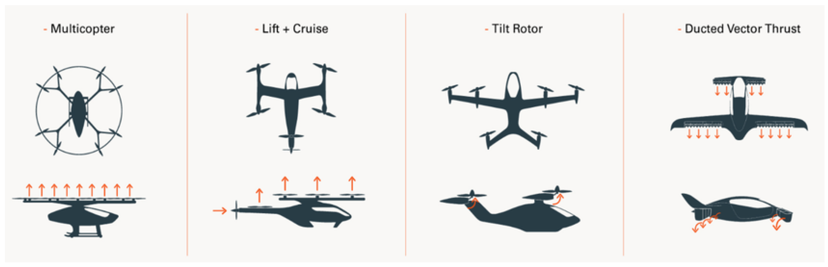
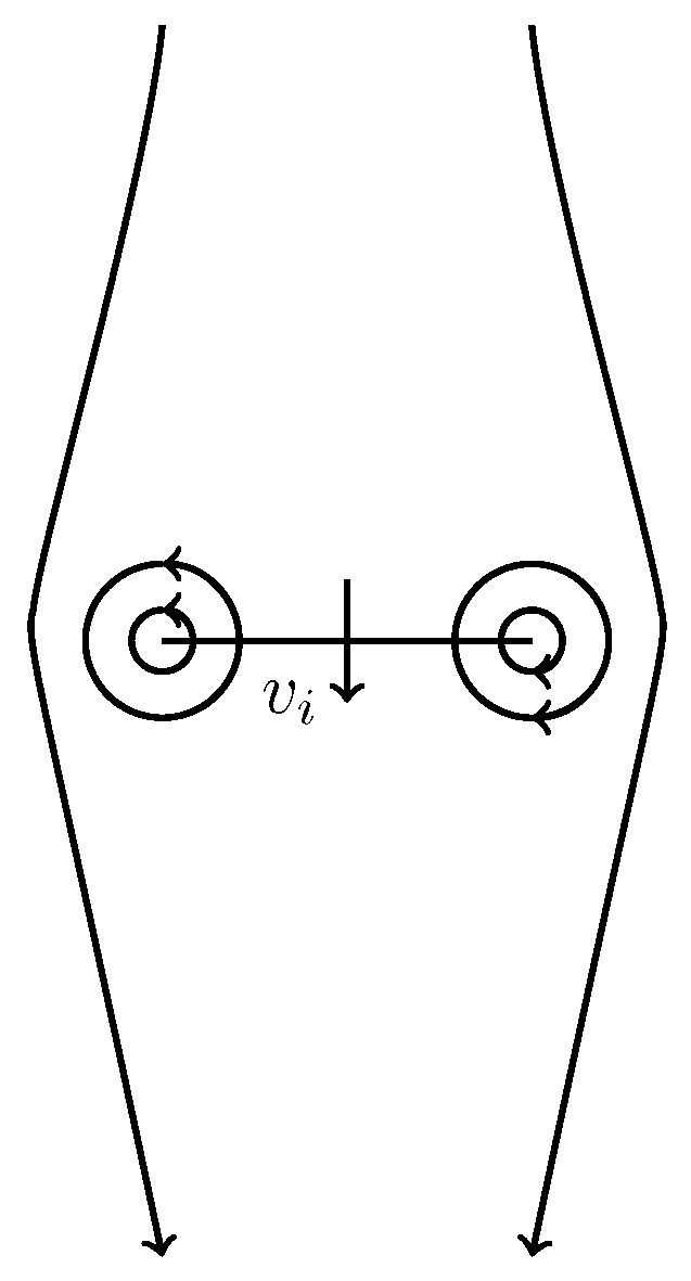
- Multicopters: This configuration is relatively simple and can be very efficient during vertical take-off, landing, and hovering. However, lacking wings, multicopters are not efficient during the cruise phase [15]. For this reason, they are primarily suited for UAM applications rather than RAM.
- Lift and cruise: These aircraft merge the multicopter with a standard aircraft for the cruise flight, overcoming the limitations of multicopters. Usually, in order to maximize range, these concepts are designed with fewer, shorter blades. This helps in reducing the drag during cruise flight. However, the small size of the propellers creates a problem in terms of noise emissions, due to the high blade tip speed.
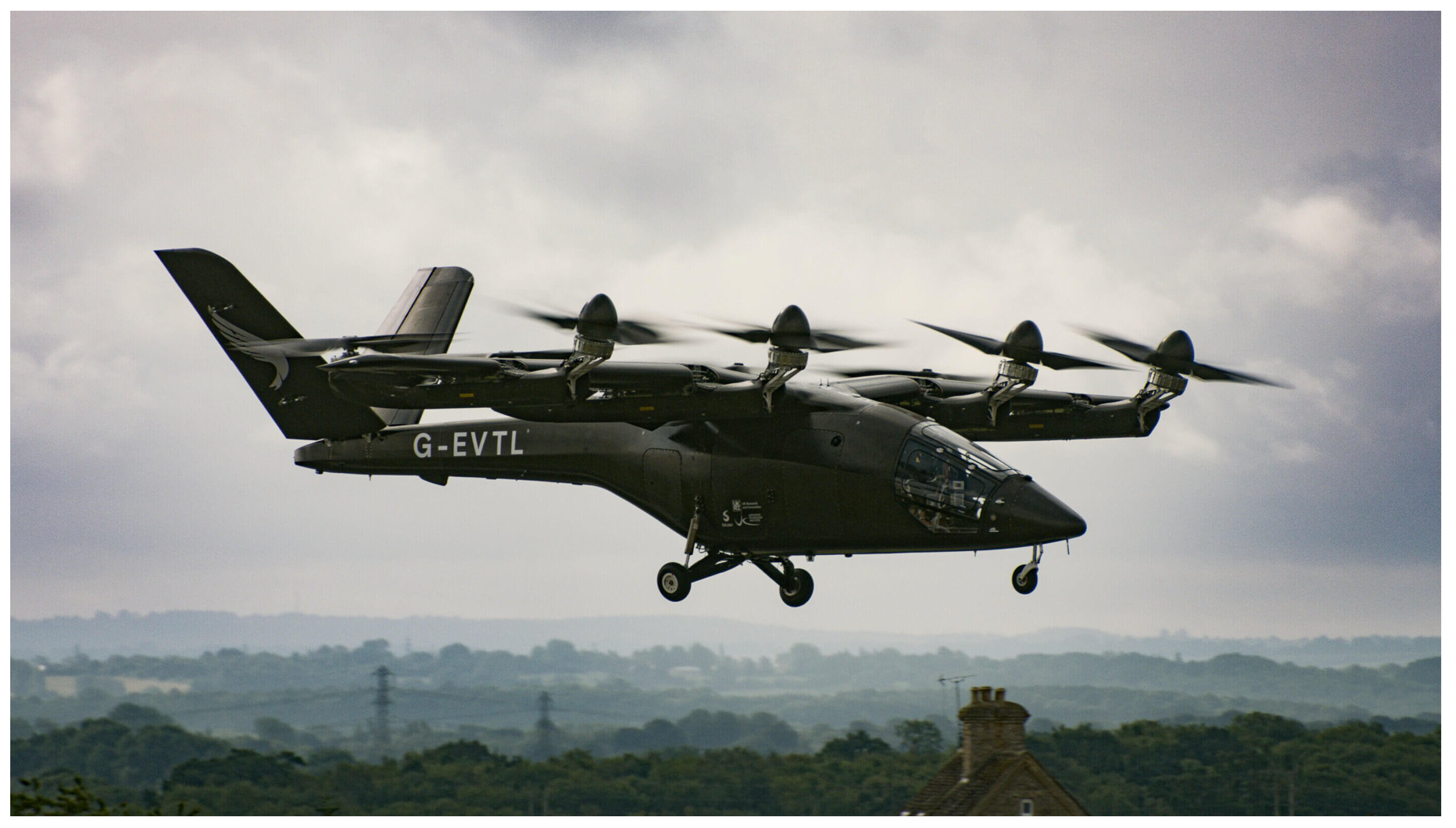
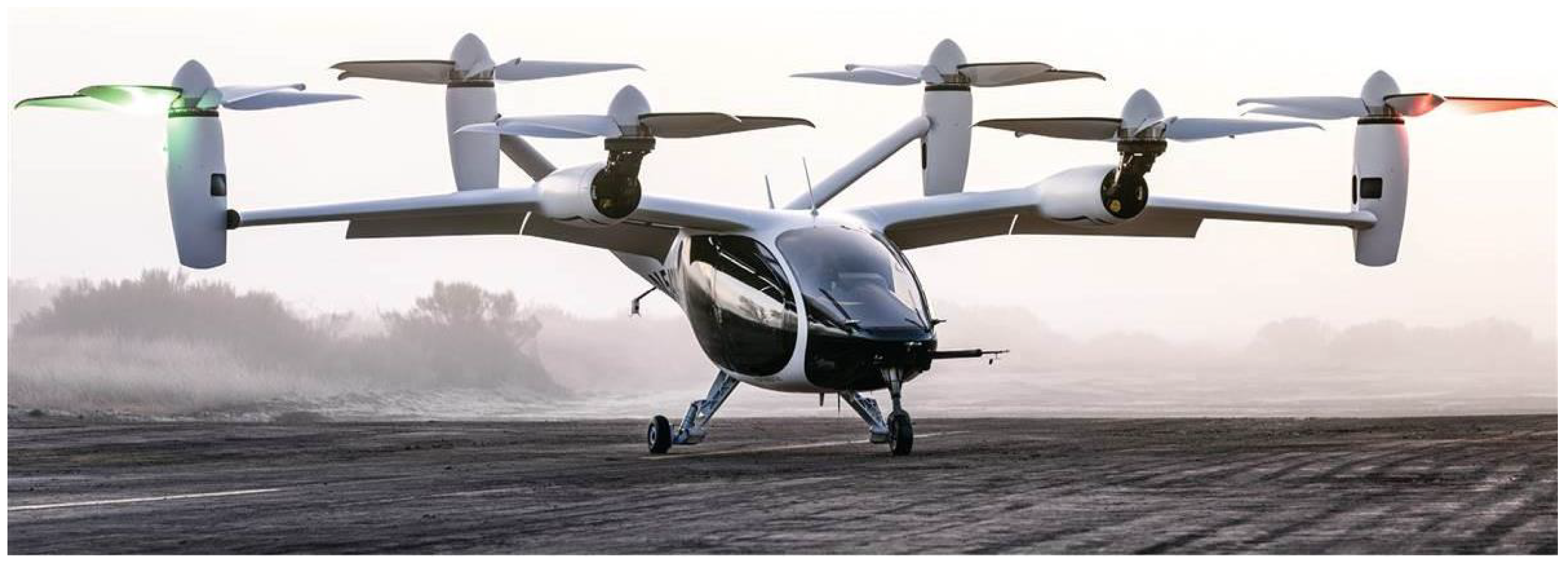
- Tilt rotor (TR): This architecture either involves the wing and propellers, or the propellers alone, tilting to allow the aircraft transition form hover to forward flight. In general, this configuration requires a more complex design, aimed at achieving a compromise solution that ensures good efficiency during all phases of flight while reducing inert mass during the cruise phase, compared with lift and cruise configurations [16]. The vertical take-off phase, however, requires the propellers to be large and rotating at low speed. This means that either the motors need to be large and heavy or a gearbox is required.
- Ducted vectored trust (DVT): this solution features ducted propellers, which offer advantages in terms of both efficiency and safety. The presence of the duct reduces losses near the propeller tips, enhancing efficiency, and allows the propellers to continue operating even in the event of collisions with birds or partial propeller damage. Ducted propellers can be integrated into the structure in two main ways: they can be placed away from the airframe, similar to conventional aircraft, or they can be integrated into the wings or fuselage structure, which results in greater aerodynamic coupling.
2. Regulatory Framework: European and American Perspectives
2.1. VTOL Takeoff Mass-Based Classification
2.1.1. EASA Classifications (Special Condition VTOL-SC-VTOL)
- Light VTOL: For aircraft with a maximum take-off mass of up to (approximately 4400 pound) [19]. This category typically includes VTOLs designed to carry few passengers or limited cargo and is subject to simplified certification requirements.
- Heavy VTOL: Includes aircraft over . In this case, safety and certification requirements are stricter, as these aircraft have a more significant impact on the environment, public safety, and infrastructure. Regulations generally require advanced redundancy, flight control, and risk mitigation systems in case of failures.
2.1.2. FAA Classifications (for Light VTOL Aircraft)
2.2. VTOL Application-Based Classification
- Commercial and transport VTOLs: these aircraft, which are generally heavier, must comply with stricter regulations regarding safety systems and the ability to operate in congested environments, such as urban areas.
- Light VTOLs for limited operations: aircraft under (especially in the eVTOL sector) may be regulated as ultralight, but only if used for non-commercial purposes.
2.3. Reference Values for VTOL Speeds and Altitudes
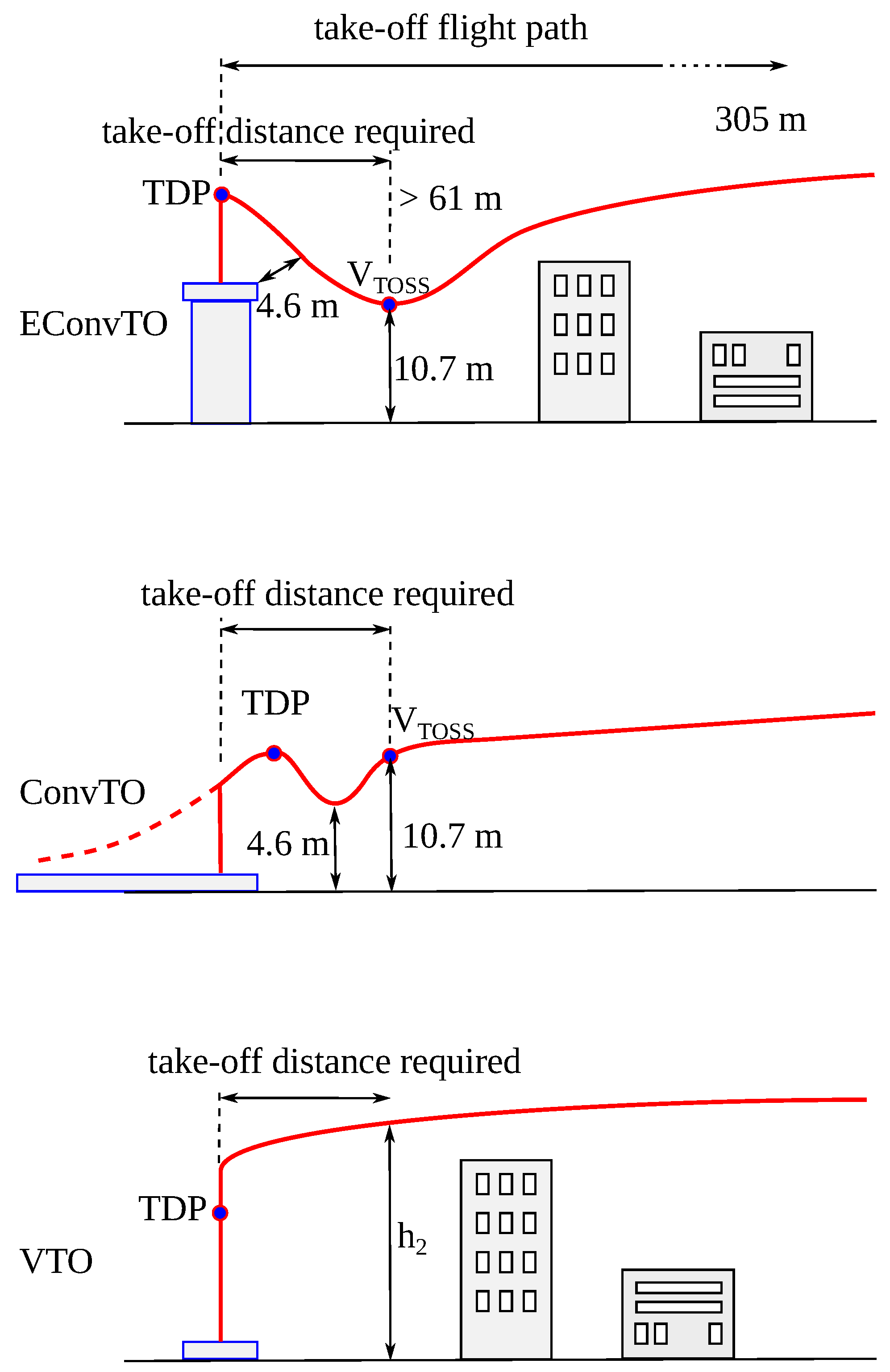
2.3.1. Take-Off
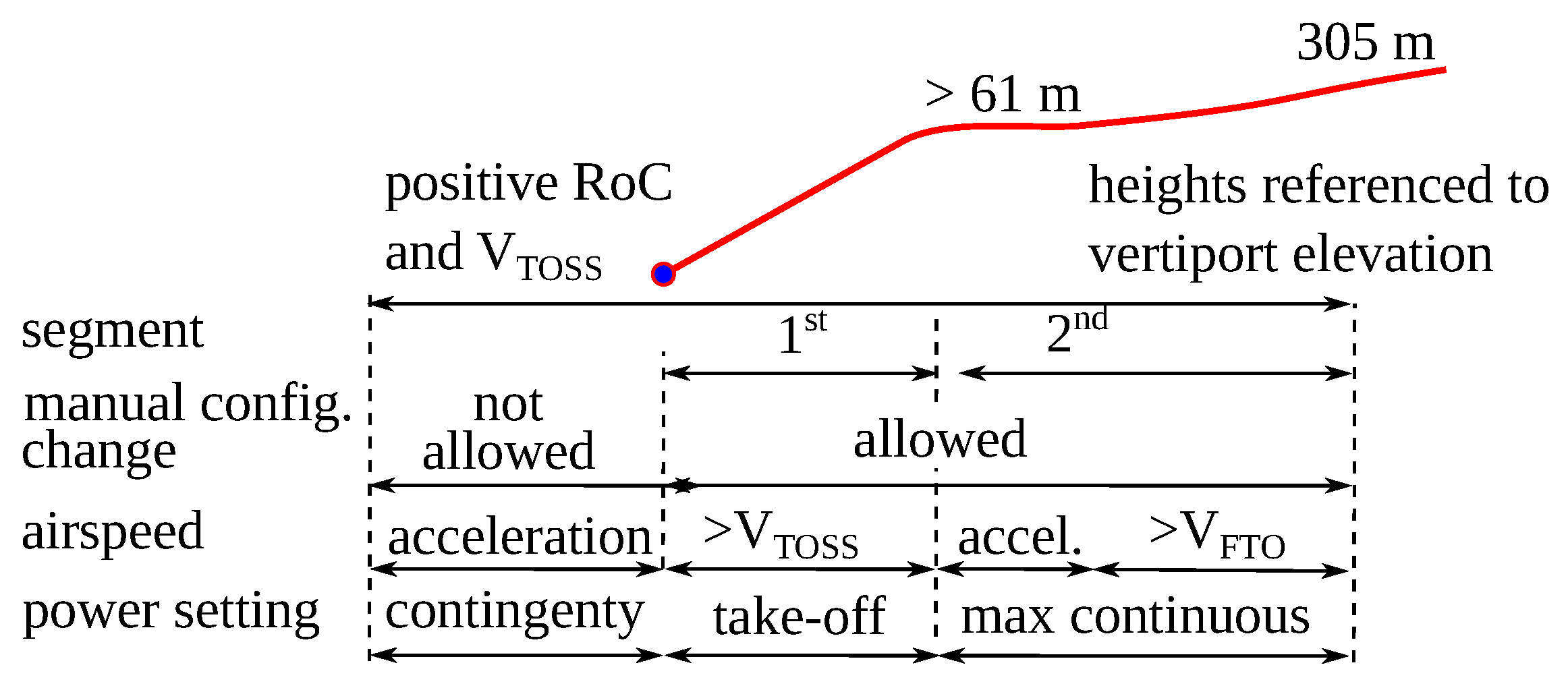
2.3.2. Climb
- First segment: From the altitude at which is reached (typically for small VTOL aircraft , i.e., feet) to . The minimum gradient required is .
- Second segment: From to . The minimum gradient required is .
2.3.3. Cruise
2.3.4. Vertical Landing
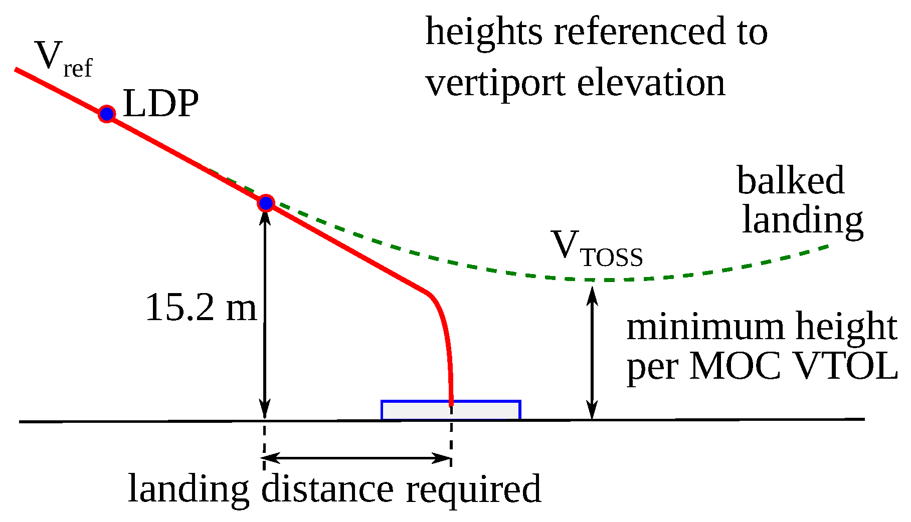
2.3.5. Balked Landing
2.4. Accelerations
2.5. Acoustic Footprint
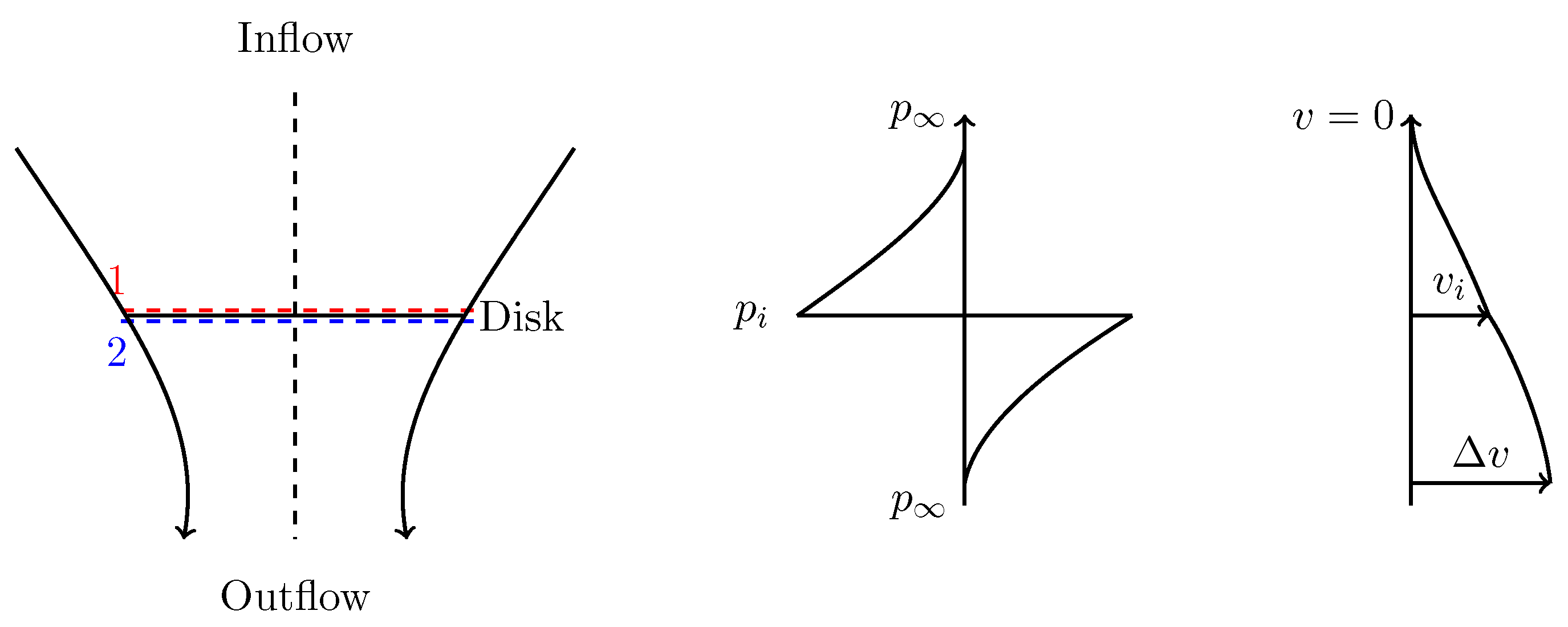
3. Propulsion System Model
- The airflow through the rotor disk is uniform.
- Non-ideal effects like compressibility and flow separation can be neglected.
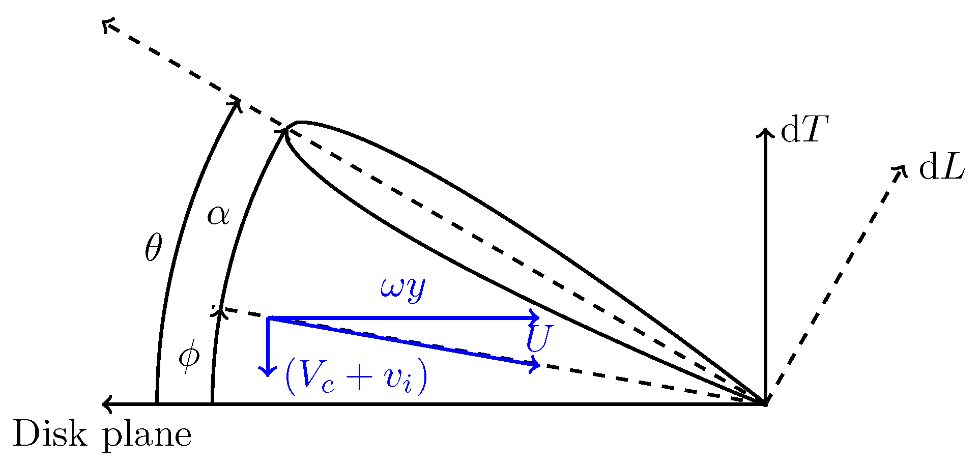
3.1. Aerodynamic Loads
Non-Ideal Flow Analysis
3.2. Ducted Fans
3.3. Motor Requirements
4. Developed Aircraft
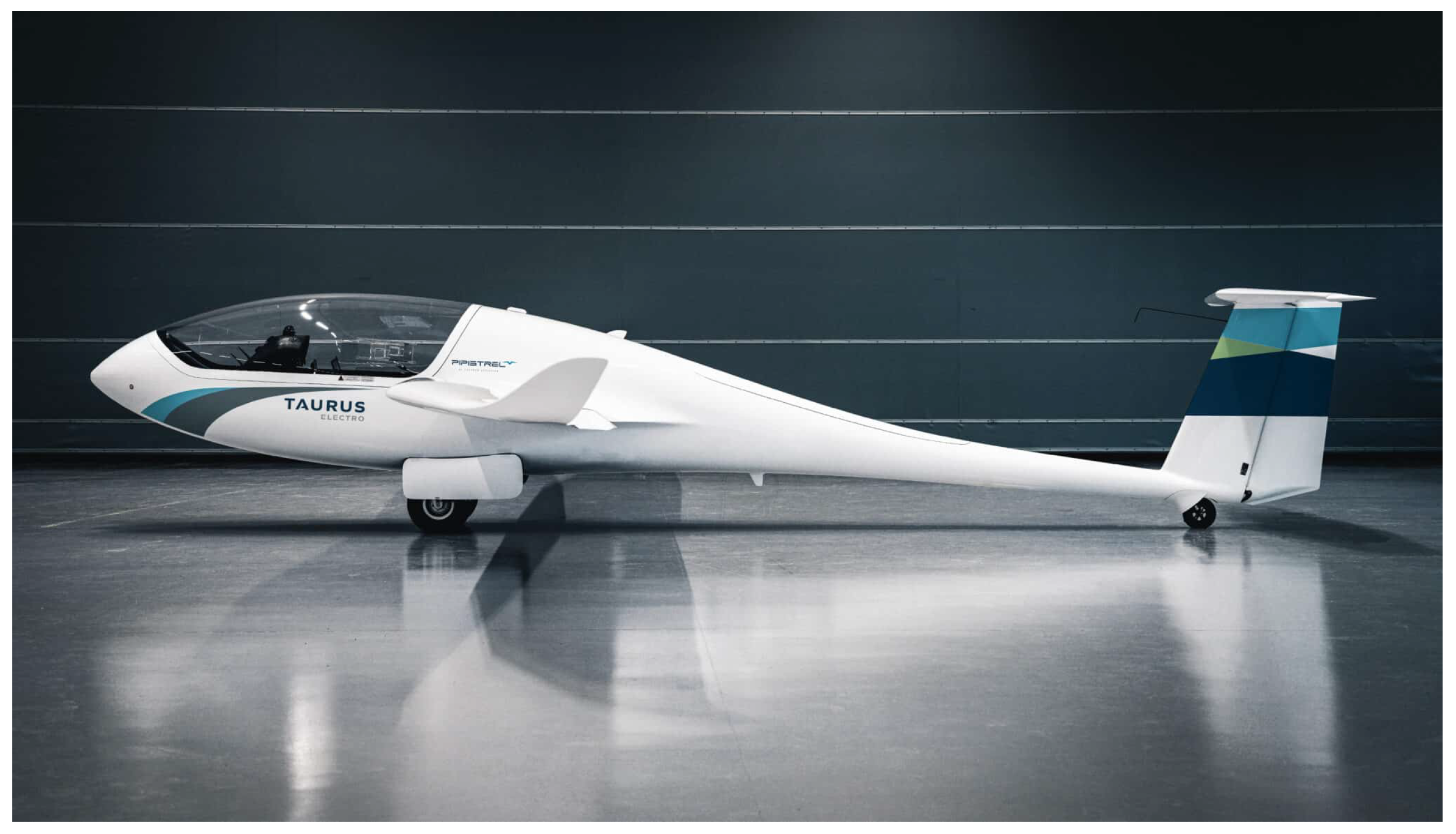
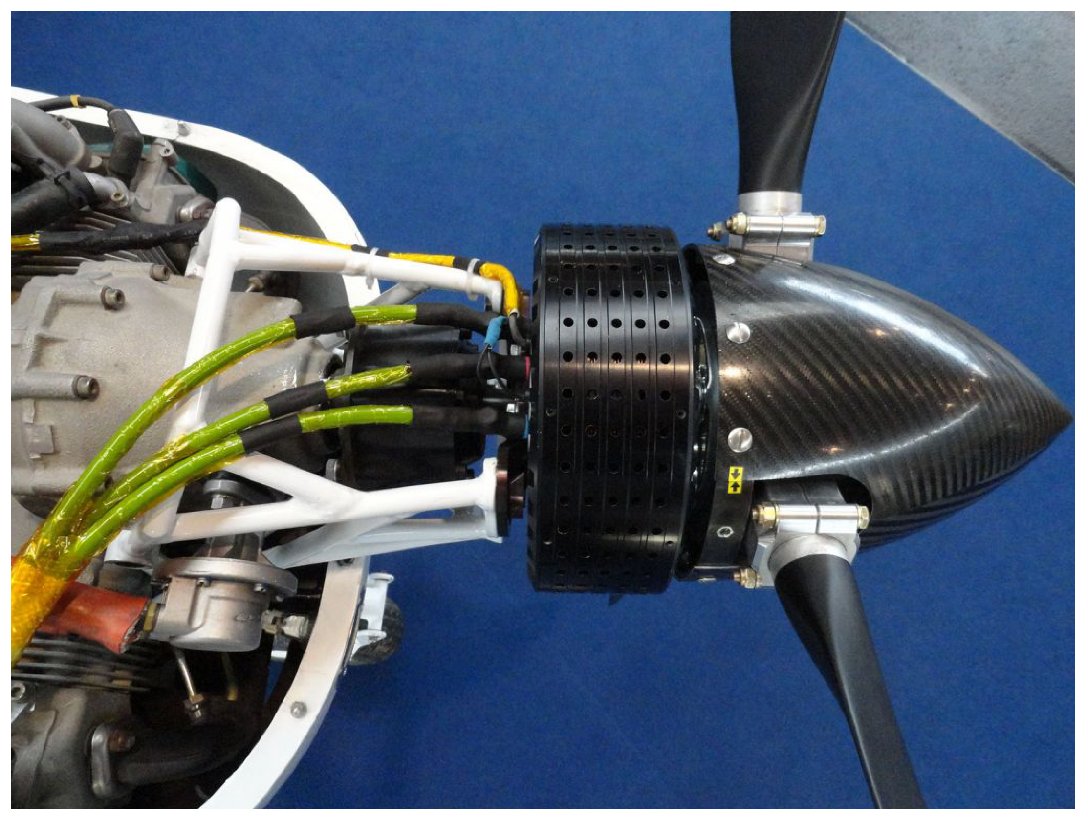
4.1. STOL Aircraft and Gliders
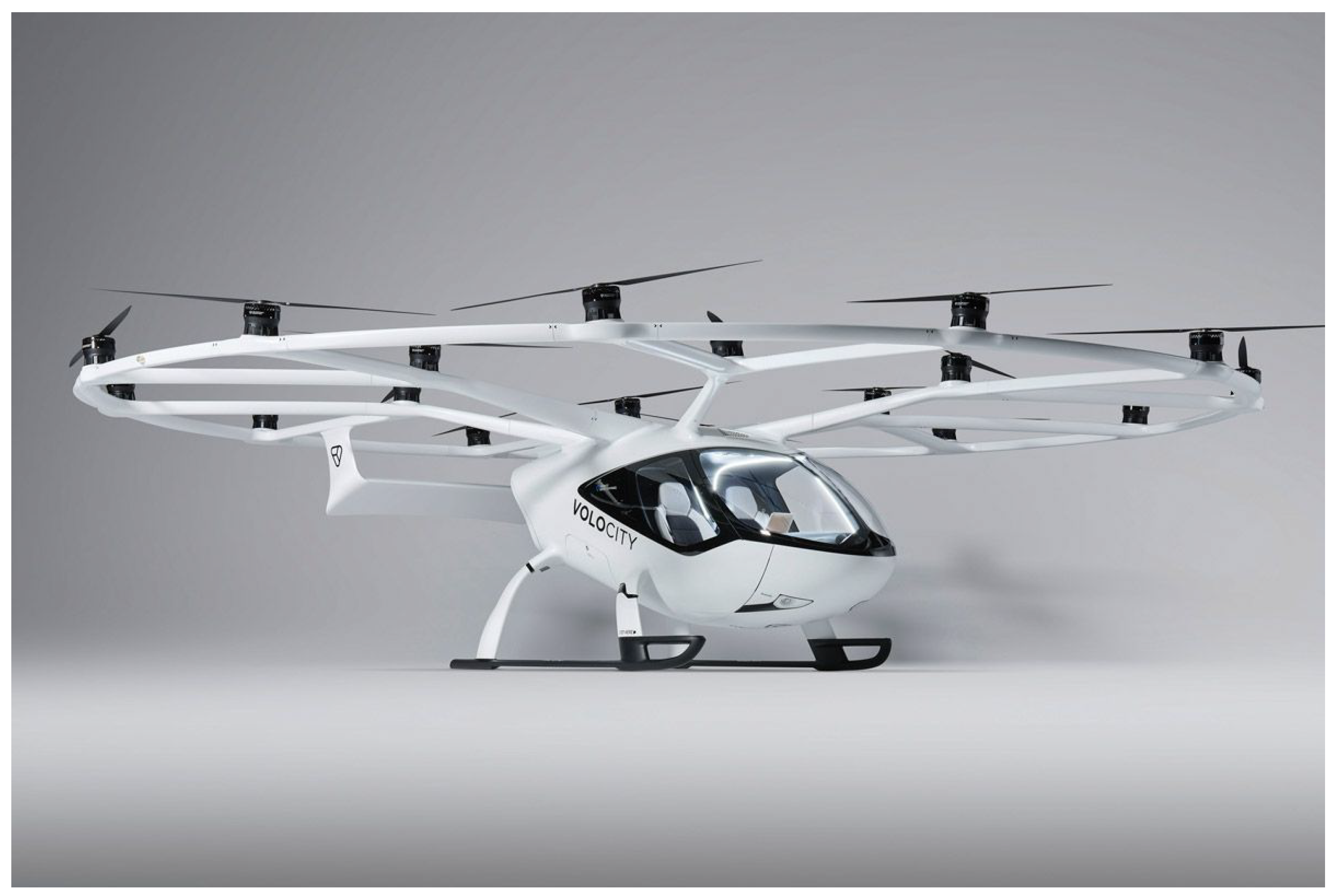
4.2. Multicopters
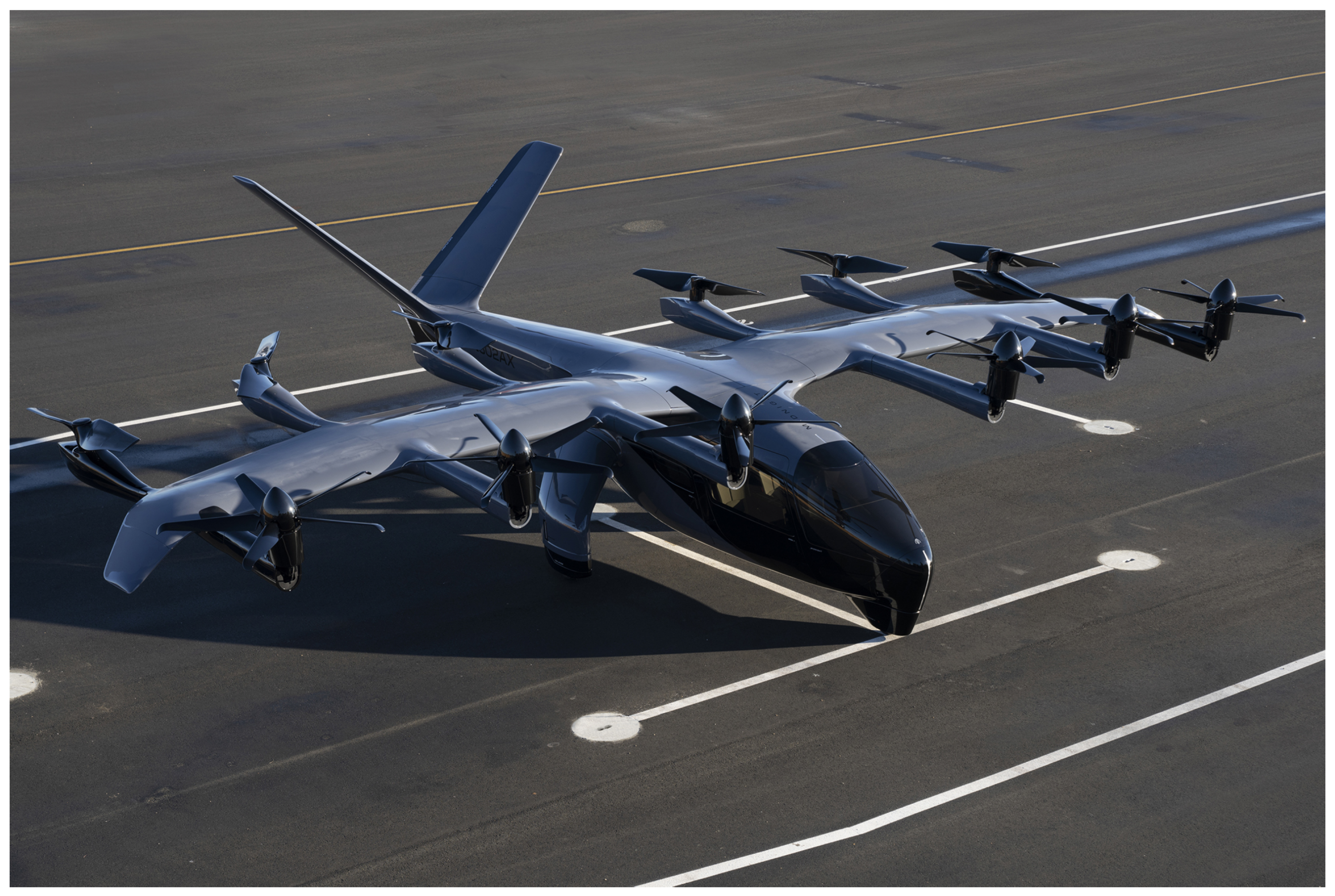
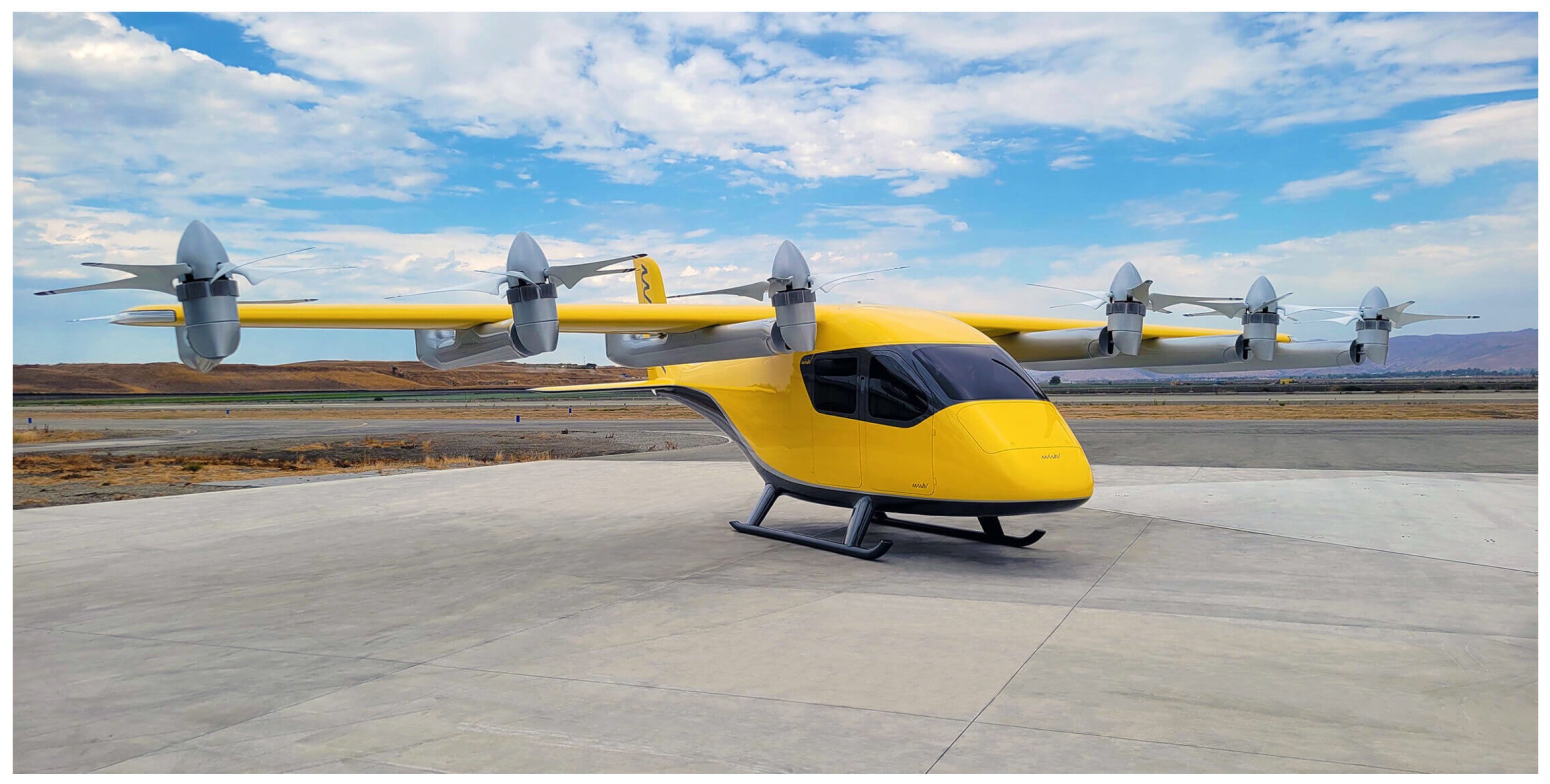
4.3. Lift and Cruise
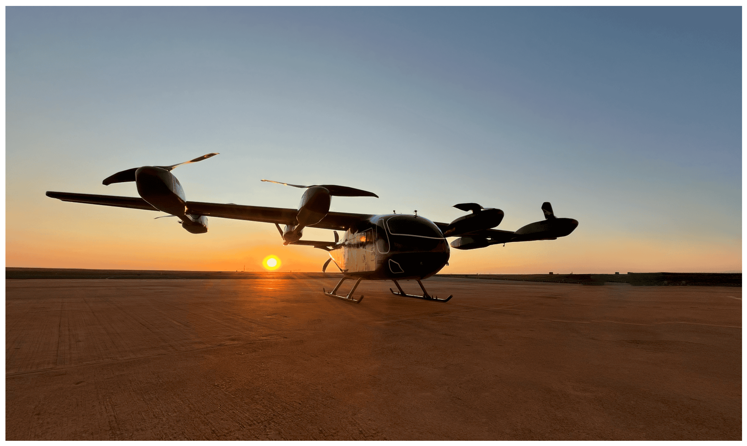
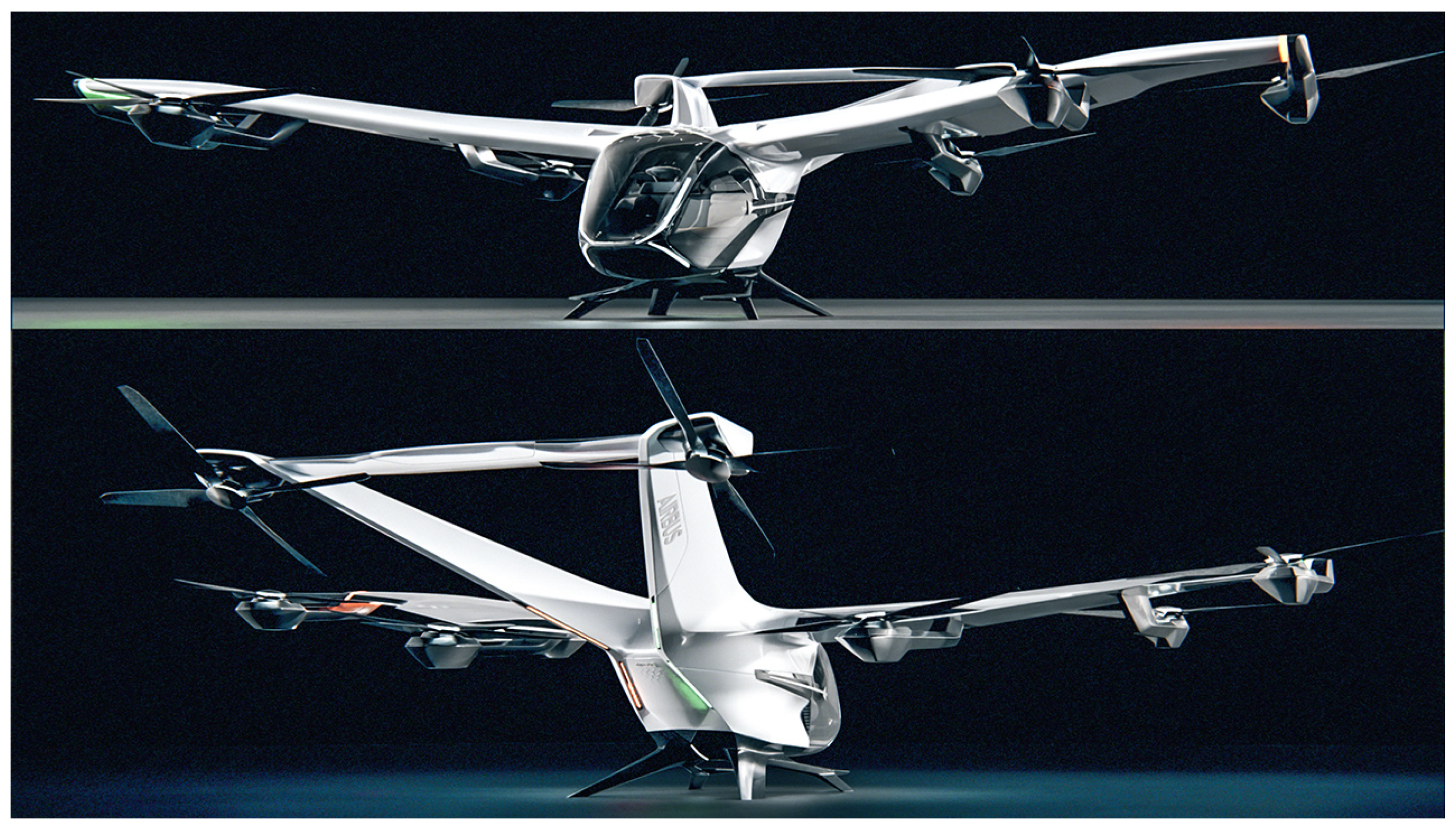
4.4. Tilt Rotor and Tilt Wing
4.5. Ducted Vectored Thrust
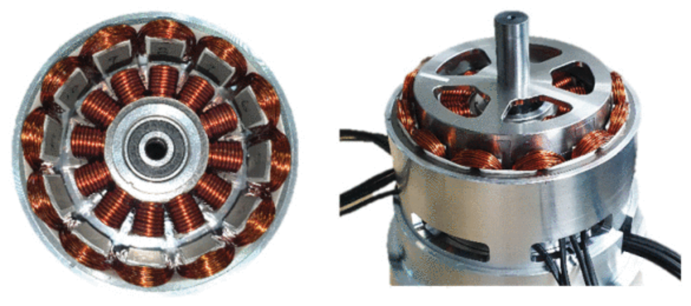
5. Electric Motor Characteristics for eVTOL
- High power density and efficiency: this ensures that, for a given power output, the electric motor weight and size are minimized, contributing to the overall performance and range of the aircraft.
- Low torque ripple: this minimizes motor vibrations, which directly reduces the system noise pollution, a critical factor for urban operations.
- Robust fault-tolerance and post-fault operation capabilities: these ensure that the system can continue functioning effectively even in the event of a fault, enhancing reliability and safety (and profitability). At the same time, great importance must be given to self-diagnostics and data analysis for fault prediction. This enables preventive maintenance actions and maximizes asset availability. All of this translates into specific requirements for both design (e.g., the integration of sensors where necessary) and testing (including endurance testing, artificial fault introduction, reliability enhancement testing, and environmental testing—particularly for air-cooled motors).
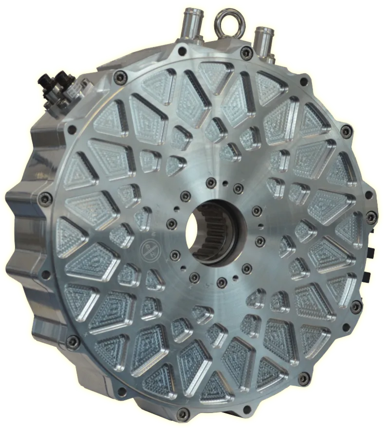
5.1. Power Density Improvement Strategies
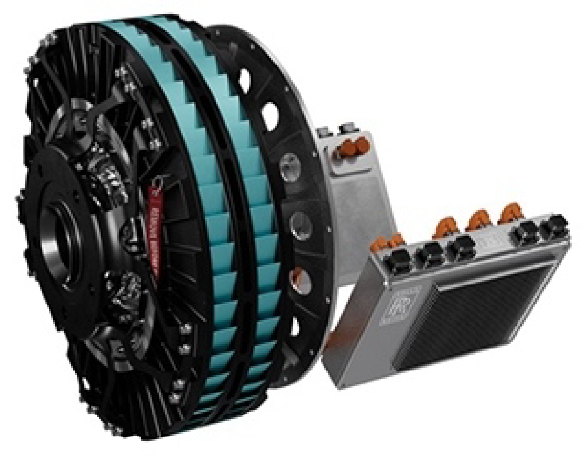
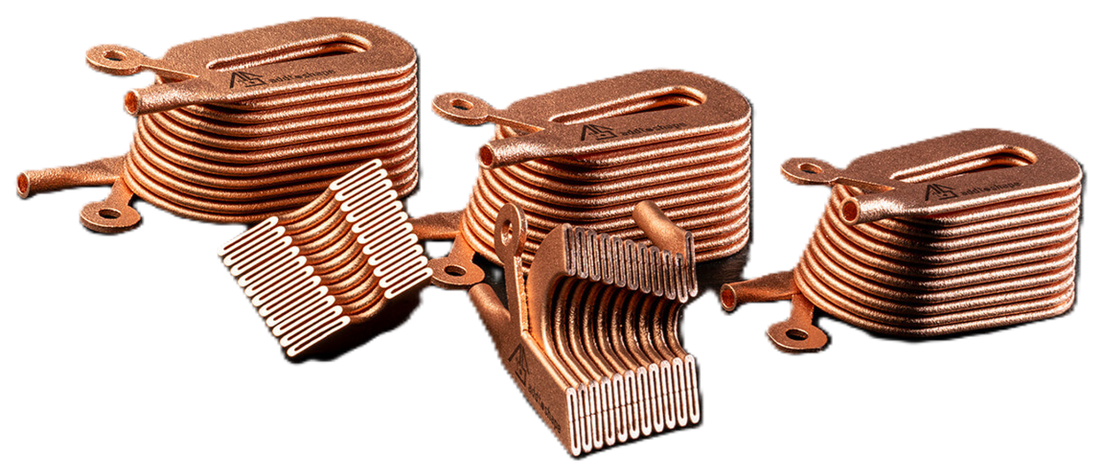
5.2. Advanced Cooling Strategies
6. Conclusions
Funding
Conflicts of Interest
Abbreviations
| DEP | Distributed electric propulsion |
| DL | Disk loading |
| DVT | Ducted vectored thrust |
| EASA | European Union Aviation Safety Agency |
| EPU | Electrical power unit |
| ESS | Energy storage system |
| eVTOL | Electric VTOL |
| FAA | Federal Aviation Administration |
| GOES | Grain-oriented electrical steel |
| LDP | Landing decision point |
| MTOM | Maximum take-off mass |
| MTOP | Maximum take-off power |
| NVH | Noise vibration and harshness |
| P/L | Payload |
| PMSM | Permanent-magnet synchronous motor |
| RAM | Regional air mobility |
| RMS | Root mean square |
| SC-VTOL | Special Condition for VTOL |
| STOL | Standard take-off and landing |
| TFM | Transverse flux machine |
| TR | Tilt rotor |
| UAM | Urban air mobility |
| VTOL | Vertical take-off and landing |
References
- Cao, W.; Mecrow, B.C.; Atkinson, G.J.; Bennett, J.W.; Atkinson, D.J. Overview of Electric Motor Technologies Used for More Electric Aircraft (MEA). IEEE Trans. Ind. Electron. 2012, 59, 3523–3531. [Google Scholar] [CrossRef]
- Gerada, C.; Galea, M.; Kladas, A. Electrical machines for aerospace applications. In Proceedings of the 2015 IEEE Workshop on Electrical Machines Design, Control and Diagnosis (WEMDCD), Torino, Italy, 26–27 March 2015; pp. 79–84. [Google Scholar] [CrossRef]
- Sayed, E.; Abdalmagid, M.; Pietrini, G.; Sa’adeh, N.M.; Callegaro, A.; Goldstein, C.; Emadi, A. Review of Electric Machines in More/Hybrid/Turbo Electric Aircraft. IEEE Trans. Transp. Electrif. 2021, 7, 2976–3005. [Google Scholar] [CrossRef]
- Lv, S.; Wang, X.; Lu, W.; Zhang, J.; Ni, H. The Influence of Temperature on the Capacity of Lithium Ion Batteries with Different Anodes. Energies 2022, 15, 60. [Google Scholar] [CrossRef]
- Lin, D.; Liu, Y.; Cui, Y. Reviving the lithium metal anode for high-energy batteries. Nat. Nanotechnol. 2017, 12, 194–206. [Google Scholar] [CrossRef] [PubMed]
- Samaniego, B.; Carla, E.; O’Neill, L.; Nestoridi, M. High specific energy Lithium Sulfur cell for space application. E3S Web Conf. 2017, 16, 08006. [Google Scholar] [CrossRef]
- Berg, E.J.; Villevieille, C.; Streich, D.; Trabesinger, S.; Novák, P. Rechargeable Batteries: Grasping for the Limits of Chemistry. J. Electrochem. Soc. 2015, 162, A2468. [Google Scholar] [CrossRef]
- Offer, G.; Zhang, T.; Marinescu, M.; Minton, G.; Purkayastha, R.; O’Neill, L.; Wild, M. Understanding Lithium Sulfur Cells, Modelling the Mechanisms behind Voltage- and Capacity-Drop during Discharge. In ECS Meeting Abstracts; The Electrochemical Society, Inc.: Philadelphia, PA, USA, 2016; p. 775. [Google Scholar] [CrossRef]
- Hagen, M.; Hanselmann, D.; Ahlbrecht, K.; Maça, R.; Gerber, D.; Tübke, J. Lithium–Sulfur Cells: The Gap between the State-of-the-Art and the Requirements for High Energy Battery Cells. Adv. Energy Mater. 2015, 5, 1401986. [Google Scholar] [CrossRef]
- Cerdas, F.; Titscher, P.; von Drachenfels, N.; Schmuch, R.; Winter, M.; Kwade, A.; Herrmann, C. Exploring the Effect of Increased Energy Density on the Environmental Impacts of Traction Batteries: A Comparison of Energy Optimized Lithium-Ion and Lithium-Sulfur Batteries for Mobility Applications. Energies 2018, 11, 150. [Google Scholar] [CrossRef]
- (EASA), E.U.A.S.A. Prototype Technical Design Specifications for Vertiports. 2022. Available online: https://www.easa.europa.eu/en/document-library/general-publications/prototype-technical-design-specifications-vertiports (accessed on 12 December 2024).
- UrbanV. Available online: https://www.urbanv.com/it/uv-0-vertiporto-di-test/ (accessed on 12 December 2024).
- Skyport. Available online: https://skyports.net/vertiports/ (accessed on 12 December 2024).
- Kopyt, A.; Kaczmarek, K.; Sochacki, M.; Stephens, C. Urban Air Mobility Traffic Analysis Tool for Airspace Involving Vertiport Hub Operations to Examine Simulated Conflicts. In Proceedings of the 2024 AIAA DATC/IEEE 43rd Digital Avionics Systems Conference (DASC), San Diego, CA, USA, 29 September–3 October 2024; pp. 1–6. [Google Scholar] [CrossRef]
- Pradeep, P.; Wei, P. Energy-Efficient Arrival with RTA Constraint for Multirotor eVTOL in Urban Air Mobility. J. Aerosp. Inf. Syst. 2019, 16, 263–277. [Google Scholar] [CrossRef]
- Chauhan, S.; Martins, J. Tilt-Wing eVTOL Takeoff Trajectory Optimization. J. Aircr. 2019, 57, 1–20. [Google Scholar] [CrossRef]
- Chahba, S.; Sehab, R.; Morel, C.; Krebs, G.; Akrad, A. Fast Sizing Methodology and Assessment of Energy Storage Configuration on the Flight Time of a Multirotor Aerial Vehicle. Aerospace 2023, 10, 425. [Google Scholar] [CrossRef]
- (EASA), E.U.A.S.A. Easy Access Rules for Small Category VCA. 2024. Available online: https://www.easa.europa.eu/en/document-library/easy-access-rules/easy-access-rules-small-category-vca (accessed on 10 December 2024).
- (EASA), E.U.A.S.A. Special Condition for VTOL and Means of Compliance. 2024. Available online: https://www.easa.europa.eu/en/document-library/product-certification-consultations/special-condition-vtol (accessed on 10 December 2024).
- (FAA), F.A.A. Urban Air Mobility (UAM) Concept of Operations. 2023. Available online: https://www.faa.gov/air-taxis/uam_blueprint (accessed on 10 December 2024).
- Joby Aviation. Available online: https://www.jobyaviation.com (accessed on 14 January 2025).
- Lilium. Available online: https://jet.lilium.com (accessed on 14 January 2025).
- Vertical Aerospace. Available online: https://vertical-aerospace.com (accessed on 14 January 2025).
- ISO 2631-1:1997; Mechanical Vibration and Shock—Evaluation of Human Exposure to Whole-Body Vibration—Part 1: General Requirements. International Organization for Standardization: Geneva, Switzerland, 1997.
- Rizzi, S.A.; Huff, D.L.; Boyd, D.D.; Bent, P.; Henderson, B.S.; Pascioni, K.A.; Sargent, D.C.; Josephson, D.L.; Marsan, M.; He, H.B.; et al. Urban Air Mobility Noise: Current Practice, Gaps, and Recommendations. 2020. Available online: https://ntrs.nasa.gov/citations/20205007433 (accessed on 14 January 2025).
- Russell, C.R.; Basset, P.M.; Onera. Conceptual Design of Environmentally Friendly Rotorcraft—A Comparison of NASA and ONERA Approaches. In Proceedings of the Vertical Flight Society 71st Annual Forum, Virginia Beach, VA, USA, 5–7 May 2015.
- Seddon, B.; Newman, S. Basic Helicopter Aerodynamics, 2nd ed.; Wiley: Hoboken, NJ, USA, 2001. [Google Scholar]
- Kim, K.C. Analytical Calculations of Helicopter Torque Coefficient (CQ) and Thrust Coefficient (CT) Values for the Helicopter Performance (HELPE) Model; US Army Research Laboratory: Adelphi, MD, USA, 1999. [Google Scholar]
- Velis Electro. Available online: https://www.pipistrel-aircraft.com/products/velis-electro/ (accessed on 14 January 2025).
- Pipisterl Taurus Electro G4. Available online: https://www.pipistrel-aircraft.com/products/taurus-electro/ (accessed on 15 January 2025).
- Volocopter Volocity. Available online: https://www.volocopter.com/en/solutions/volocity (accessed on 15 January 2025).
- EVE Air Mobility. Available online: https://www.eveairmobility.com/ (accessed on 15 January 2025).
- Airbus CityAirbus. Available online: https://www.airbus.com/en/innovation/energy-transition/hybrid-and-electric-flight/cityairbus-nextgen (accessed on 17 January 2025).
- Archer. Available online: https://archer.com/ (accessed on 17 January 2025).
- Wisk Aero. Available online: https://wisk.aero/aircraft/ (accessed on 17 January 2025).
- Vertical Aerospace VX4. Available online: https://vertical-aerospace.com/meet-the-vx4/ (accessed on 17 January 2025).
- Supernal. Available online: https://www.supernal.aero/aircraft/ (accessed on 17 January 2025).
- Airbus Vahana. Available online: https://www.airbus.com/en/innovation/low-carbon-aviation/urban-air-mobility/cityairbus-nextgen/vahana (accessed on 17 January 2025).
- Perdolt, D.; Thiele, M.; Milz, D.; May, M.; Kuchar, R.; Hornung, M. Comparison of Multi-Fidelity Rotor Analysis Tools for Transitional and Low Speed Flight Regimes. In Proceedings of the Deutscher Luft-und Raumfahrtkongress 2021, Bremen, Germamy, 31 August–2 September 2021. [Google Scholar] [CrossRef]
- Bianchi, N.; Bolognani, S. Design techniques for reducing the cogging torque in surface-mounted PM motors. IEEE Trans. Ind. Appl. 2002, 38, 1259–1265. [Google Scholar] [CrossRef]
- Bianchi, N.; Michieletto, D.; Cinti, L.; Contò, C.; Carlet, P.G.; Brunetti, M.; Nesci, A. Permanent Magnet Synchronous Motor Drives for More-Electric Aircraft. In Proceedings of the 2022 International Symposium on Power Electronics, Electrical Drives, Automation and Motion (SPEEDAM), Sorrento, Italy, 22–24 June 2022; pp. 871–876. [Google Scholar] [CrossRef]
- Brunetti, M.; Nesci, A.; Bianchi, N. Conceptual design of a distributed electric anti-torque system for enhanced helicopter safety and performance. CEAS Aeronaut. J. 2023, 15, 545–563. [Google Scholar] [CrossRef]
- Fabri, G.; Parasiliti, F.; Tursini, M.; Villani, M.; Castellini, L. PM brushless motor for helicopters electric tail rotor drive system. In Proceedings of the 2017 IEEE International Electric Machines and Drives Conference (IEMDC), Miami, FL, USA, 21–24 May 2017; pp. 1–7. [Google Scholar] [CrossRef]
- Barcaro, M.; Bianchi, N.; Magnussen, F. Analysis and tests of a dual three-phase 12-slot 10-pole permanent magnet motor. In Proceedings of the 2009 IEEE Energy Conversion Congress and Exposition, San Jose, CA, USA, 20–24 September 2009; pp. 3587–3594. [Google Scholar] [CrossRef]
- Bianchi, N.; Stoppato, A. Thermal Analysis of a Multi-Three-Phase PM Motor in Nominal, Overload and Post-Fault Operations. In Proceedings of the 2024 International Symposium on Power Electronics, Electrical Drives, Automation and Motion (SPEEDAM), Napoli, Italy, 19–21 June 2024; pp. 806–811. [Google Scholar] [CrossRef]
- Michieletto, D.; Bianchi, N.; Brunetti, M. Dual Three-phase Motor Fault Tolerance for Modern Transport. In Proceedings of the 2021 International Aegean Conference on Electrical Machines and Power Electronics (ACEMP) & 2021 International Conference on Optimization of Electrical and Electronic Equipment (OPTIM), Brasov, Romania, 2–3 September 2021; pp. 405–412. [Google Scholar] [CrossRef]
- Kallio, S.; Andriollo, M.; Tortella, A.; Karttunen, J. Decoupled d-q Model of Double-Star Interior-Permanent-Magnet Synchronous Machines. IEEE Trans. Ind. Electron. 2013, 60, 2486–2494. [Google Scholar] [CrossRef]
- Siemens. Available online: https://www.siemens.com/it/it.html (accessed on 20 December 2024).
- Hwang, S.W.; Son, D.K.; Park, S.H.; Lee, G.H.; Yoon, Y.D.; Lim, M.S. Design and Analysis of Dual Stator PMSM with Separately Controlled Dual Three-Phase Winding for eVTOL Propulsion. IEEE Trans. Transp. Electrif. 2022, 8, 4255–4264. [Google Scholar] [CrossRef]
- Yasa. Available online: https://yasa.com/ (accessed on 20 December 2024).
- Rolls Royce. Available online: https://www.rolls-royce.com/products-and-services.aspx (accessed on 20 December 2024).
- Emrax. Available online: https://emrax.com/ (accessed on 28 December 2024).
- Zucker, O.S.; Blumenau, L.; Liu, C.; Yu, P.K. New High Specific Power Motor Technology for All-Electric Class III UAVs. In Proceedings of the 2018 IEEE International Power Modulator and High Voltage Conference (IPMHVC), Jackson, WY, USA, 3–7 June 2018; pp. 58–63. [Google Scholar] [CrossRef]
- Hebri, M.; Rebhaoui, A.; Bauw, G.; Lecointe, J.P.; Duchesne, S.; Zito, G.; Abdenour, A.; Santos, V.; Mallard, V.; Maier, A. Power density improvement of axial flux permanent magnet synchronous motor by using different magnetic materials. COMPEL Int. J. Comput. Math. Electr. Electron. Eng. 2023, 42, 929–946. [Google Scholar] [CrossRef]
- Jiang, X.; Huang, W.; Cao, R.; Hao, Z.; Jiang, W. Electric Drive System of Dual-Winding Fault-Tolerant Permanent Magnet Motor for Aerospace Applications. IEEE Trans. Ind. Electron. 2015, 62, 7322–7330. [Google Scholar] [CrossRef]
- Wang, J.; Dong, J.; Niasar, M.G.; Zhu, G.; Bauer, P. Power Density Limits of Propulsion Motor for Electric Aircraft: A Study on Insulation Thickness. In Proceedings of the 2024 International Conference on Electrical Machines (ICEM), Torino, Italy, 1–4 September 2024; pp. 1–7. [Google Scholar] [CrossRef]
- Arzillo, A.; Nuzzo, S.; Braglia, P.; Franceschini, G.; Barater, D.; Gerada, D.; Gerada, C. An Analytical Approach for the Design of Innovative Hairpin Winding Layouts. In Proceedings of the 2020 International Conference on Electrical Machines (ICEM), Online, 23–26 August 2020; Volume 1, pp. 1534–1539. [Google Scholar] [CrossRef]
- Carbonieri, M.; Venturini, G.; Popescu, M. A Practical Approach to Hairpin Winding Design: Patterns Investigation, Feasibility Verification and Fractional Slot Solutions. In Proceedings of the 2022 IEEE Energy Conversion Congress and Exposition (ECCE), Detroit, MI, USA, 9–13 October 2022; pp. 1–8. [Google Scholar] [CrossRef]
- Bianchi, N.; Berardi, G. Analytical Approach to Design Hairpin Windings in High Performance Electric Vehicle Motors. In Proceedings of the 2018 IEEE Energy Conversion Congress and Exposition (ECCE), Portland, OR, USA, 23–27 September 2018; pp. 4398–4405. [Google Scholar] [CrossRef]
- Berardi, G.; Bianchi, N. Design Guideline of an AC Hairpin Winding. In Proceedings of the 2018 XIII International Conference on Electrical Machines (ICEM), Alexandroupoli, Greece, 3–6 September 2018; pp. 2444–2450. [Google Scholar] [CrossRef]
- Wu, F.; EL-Refaie, A.M. Additively Manufactured Hollow Conductors with Integrated Cooling for High Specific Power Electrical Machines. In Proceedings of the 2020 International Conference on Electrical Machines (ICEM), Gothenburg, Sweden, 23–26 August 2020; Volume 1, pp. 1497–1503. [Google Scholar] [CrossRef]
- Wu, F.; EL-Refaie, A.M.; Al-Qarni, A. Additively Manufactured Hollow Conductors Integrated with Heat Pipes: Design Tradeoffs and Hardware Demonstration. IEEE Trans. Ind. Appl. 2021, 57, 3632–3642. [Google Scholar] [CrossRef]
- Addtoshape. Available online: https://www.addtoshape.com/ (accessed on 20 January 2025).

| Helicopter | Compound | Tilt Rotor | |||
|---|---|---|---|---|---|
| H90 | HO90 | TC90 | TR90 | TR90 Min ATR | |
| Empty weight [] | 23,330 | 26,685 | 27,772 | 28,199 | 30,472 |
| Power per engine [] | 3185 | 3133 | 4019 | 4362 | 3930 |
| Wing loading [] | - | - | 440 | 440 | 390 |
| Disk loading [] | 39 | 40 | 54 | 68 | 49 |
| Main rotor blades | 7 | 7 | 4 | 4 | 4 |
| Cruise altitude [] | 3700 | 1065 | 7300 | 10,100 | 5500 |
| Cruise speed [] | 306 | 280 | 419 | 567 | 437 |
| EVE Embraer | CityAirbus | Midnight | Aero Gen 6 | VX4 | |
|---|---|---|---|---|---|
| MTOM [] | - | >2000 | 3175 | - | - |
| Max P/L [] | - | - | 456 | 408 | 450 |
| N° of VTOL propellers | 8 | 6 | 6 | 6 | 4 |
| N° of cruise propellers | 1 | - | - | - | - |
| N° of tilt propellers | - | 2 | 6 | 6 | 4 |
| VTOL rotor blades | 2 | 4 | 2 | 4 | 4 |
| Cruise rotor blades | 5 | 4 | 5 | 5 | 5 |
| Cruise altitude [] | - | - | 610 | 760–1200 | - |
| Cruise speed [] | - | 120 | 241 | 222 | 241 |
| Range [] | 100 | 80 | 32–80 | 90 | 161 |
| Power supply | - | - | 6 battery packs | - | - |
| Acoustic footprint [dB(A)] | - | - | 45 (cruise) | - | - |
| Joby S4 | Supernal S-A2 | Vahana | |
|---|---|---|---|
| MTOM [] | 2400 | - | - |
| Max P/L [] | 453 | - | - |
| N° of propellers | 6 | 8 | 8 |
| Rotor blades | 5 | 4 | 3 |
| Peak power (per motor) [] | 236 | - | 45 |
| Cruise altitude [] | - | 457 | - |
| Cruise speed [] | 322 | 193 | - |
| Range [] | 131 (reserves included) | 39–64 | 50 |
| Power supply | - | HV fast-charging | Li-ion |
| Acoustic footprint [dB(A)] | 45 (cruise) | 65 (hover)-45 (cruise) | - |
| Siemens SP200D | YASA 750R | Rolls-Royce EPU150 | Emrax 268 | |
|---|---|---|---|---|
| Rated power | 204 | 100 | 150 | 117 |
| Maximum power | 204 () | 200 | - | 210 () |
| Rated speed [rpm] | 1300 | 3000 | 1100 | - |
| Maximum speed [rpm] | 1300 | 3250 | - | 4500 |
| Rated torque | 1500 | 400 | 1300 | 250 |
| Maximum torque | - | 790 () | 1500 | 500 |
| Efficiency | - | >95 | >95 | 96 |
| Supply voltage | 450–850 | 400–700 | 500–900 | 100–830 |
| Mass | 49 | 37 | 38 | 21.4–22.3 |
| Power density | 4.16 | 5.4 | 3.94 | 9.41–9.81 |
| Torque density | 30 | 21.4 | 39.47 | 22.4–23.4 |
| Cooling system | Liquid (Syltherm800) | Liquid | Air | Air–Water |
Disclaimer/Publisher’s Note: The statements, opinions and data contained in all publications are solely those of the individual author(s) and contributor(s) and not of MDPI and/or the editor(s). MDPI and/or the editor(s) disclaim responsibility for any injury to people or property resulting from any ideas, methods, instructions or products referred to in the content. |
© 2025 by the authors. Licensee MDPI, Basel, Switzerland. This article is an open access article distributed under the terms and conditions of the Creative Commons Attribution (CC BY) license (https://creativecommons.org/licenses/by/4.0/).
Share and Cite
Tripaldi, F.; Vianello, S.; Bianchi, N. Emerging Trends in Urban Air Mobility: An Extensive Review. Energies 2025, 18, 1426. https://doi.org/10.3390/en18061426
Tripaldi F, Vianello S, Bianchi N. Emerging Trends in Urban Air Mobility: An Extensive Review. Energies. 2025; 18(6):1426. https://doi.org/10.3390/en18061426
Chicago/Turabian StyleTripaldi, Francesco, Stefano Vianello, and Nicola Bianchi. 2025. "Emerging Trends in Urban Air Mobility: An Extensive Review" Energies 18, no. 6: 1426. https://doi.org/10.3390/en18061426
APA StyleTripaldi, F., Vianello, S., & Bianchi, N. (2025). Emerging Trends in Urban Air Mobility: An Extensive Review. Energies, 18(6), 1426. https://doi.org/10.3390/en18061426