Abstract
Ammonia (NH3) is a promising zero-carbon fuel, but it faces critical challenges in combustion utilization, especially NO emission. Intensive previous studies have been carried out to deepen the understanding towards NH3 combustion and NO emission characteristics but most of them focus on the premixed combustion mode. This work conducts both experiments and large-eddy simulations (LESs) for various NH3/CH4 mixtures, from pure methane to pure ammonia, under both premixed and non-premixed combustion modes, to gain a clear insight into the NO emission performance and formation mechanism of the two combustion modes. It is shown that the non-premixed combustion exhibits a stratified flame appearance, mainly due to the different reactivity between CH4 and NH3. Accordingly, the non-premixed combustion mode produces the lower NO emission across all NH3 blending ratios with respect to its premixed counterpart. Further, LES results show that the flame stratification is responsible for the lower NO emission by creating a strong fuel-rich region in the combustor center where a part of NH3 undergoes thermal cracking into H2 and N2. In addition, the performance of several existing NH3/CH4 mechanism models is estimated by comparing the predicted NO emissions against the present experimental measurement for both premixed and non-premixed mixing patterns, and the present proposed model shows the lowest error among the candidates.
1. Introduction
Ammonia (NH3) has received intensive attention recently owing to its zero-carbon nature and mature infrastructures of production, storage and distribution [1,2]. Under the global pressure of low-carbon transition, the replacement of traditional fossil fuels with NH3 in industrial combustion equipment is a promising way to reduce carbon emission. However, due to its high ignition energy, slow flame propagation speed and large N content, NH3 faces critical challenges during its combustion, such as weak flame stability, narrow flammability limit and high NO emission [3,4]. Therefore, high-efficiency and low-NO combustion technologies are urgently needed to enhance the utilization of NH3 [5,6].
Lean premixed combustion is widely adopted for controlling NO emission for fossil fuels. Its suitability for NH3 and NH3-contained fuels has been studied heavily in the past. Hayakawa et al. [7] examined the flammability limit range of an NH3/Air premixed flame and reported that a pure NH3/Air flame can be stabilized by a swirling burner with a swirl number of 0.736. Khateeb et al. [8] experimentally suggested the addition of CH4 and H2 is beneficial to widening the flammability limit range of NH3/Air premixed flames. Zhang et al. [9] carried out an experiment and LES (large-eddy simulation) modeling to reveal the regulation effects of CH4 and H2 addition on the NO emission performance of NH3/Air premixed flames. Wei et al. [10] used a large-eddy simulation (LES) to examine the blowoff mechanism of an NH3/Air premixed flame, and three main reasons were drawn: flame transition stretching, slowing down of the heat release rate and aggravation of wall heat loss.
Due to safety concerns, the non-premixed combustion mode is also widely adopted. In this regard, Somarathne et al. [11] compared the flame structure and NO emission performance between premixed and non-premixed NH3/Air swirling flames using LES. Okafor et al. [12] experimentally studied the NO emission characteristics of NH3/Air non-premixed flames under a staged combustion mode. Tu et al. [13] examined the flame chemiluminescence for NH3/CH4 mixtures under premixed and non-premixed modes.
Under non-premixed combustion, the reaction between fuel and air has been reported to be inhomogeneous. This is considered to result from non-uniform mixing in the flame shear layer. Especially for binary or ternary fuels, such as NH3/CH4, a sequential oxidation of fuel components is likely to exist due to the different ignition energies. Moreover, the C-N interaction plays a vital role in NO generation for NH3/CH4. The chemiluminescence of CH* and NH2* reported by Tu et al. [14] suggests a weaker coupling of the CH4 and NH3 flames in non-premixed flames, which could affect the NO generation process via HCN and NCO sub-routes.
In this study, experiments and LES modeling are carried out to understand how the fuel/air mixing mode influences the flame structure as well as the NO formation behavior for various NH3/CH4 mixtures. A quantitative assessment of the NO reduction potential will be made between premixed and non-premixed combustion modes. In addition, the present NO emission data measured by a standard swirling burner will be used as the benchmark database for validation of NH3/CH4 mechanisms.
2. Methodology
2.1. Experimental Methodology
The NH3/CH4 cofiring combustion experiment is conducted on a laboratory-scale combustion test rig, as shown in Figure 1. The setup primarily includes a swirling burner, a quartz combustion chamber, a Sevenstar CS200 mass flow controller (Huacheng Electronics, Beijing, China), an MRU-OPTIMA7 (MRU, Obereisesheim, Germany) and PTM-600 (Eranntex, Shenzhen, China) flue gas analyzer and a Canon M3 digital camera (Canon, Tokyo, Japan), among other equipment. Air and fuel are supplied by an air compressor and gas cylinders, respectively, and are regulated by mass flow controllers to produce the required flowrates. The structure of the swirl burner is illustrated in Figure 2, where the red and green arrows represent the flow directions of air and fuel, respectively. In the fully premixed (FP) combustion mode (Figure 2b), fuel and air are premixed and introduced into the combustor through the outer annular channel via a swirler. In the non-premixed (NP) mode (Figure 2c), fuel is supplied through the central channel and injected radially into the combustor via eight uniformly distributed nozzles at the top, while air enters the combustor through the outer annular channel. The cylindrical combustion chamber has a diameter of 80 mm, and its length can be adjusted between 200 mm and 300 mm by replacing the quartz sleeve. The swirl number is defined as the ratio of tangential velocity to axial velocity, with its magnitude reflecting the strength of swirl in the combustion flow. In this study, the swirl number is 0.78, which corresponds to the 45° swirl vanes used in the experiment. For detailed information on the entire experimental setup, refer to the literature [15].

Figure 1.
Combustion test rig.
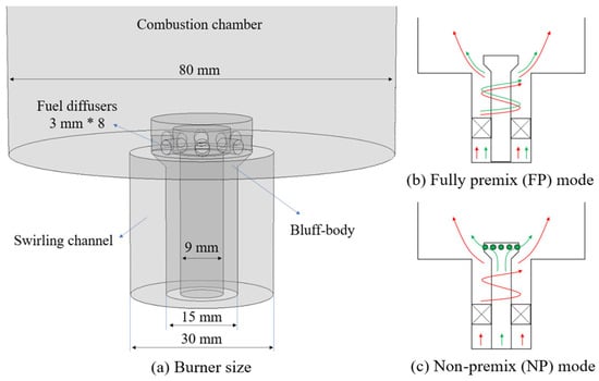
Figure 2.
Illustrations of (a) burner and burner operating configurations for (b) FP mode and (c) NP mode.
A Cannon M3 digital camara is employed to capture the mean flame images, and an MRU Optima 7 flue gas (MRU, Obereisesheim, Germany) analyzer is used to measure the concentrations of O2, CO and NO in the exhausted gas. Considering the potential unburned species, the measurement of H2, CH4 and NH3 is conducted using the PTM-600 flue gas analyzer (Eranntex, Shenzhen, China) based on the TDLAS principle. The flue gas collection probe was positioned inside the exhaust pipe, 10 cm from the pipe opening, to prevent ambient air entrainment. The collected flue gas was dried and then introduced into the flue gas analyzer for measurement. After the instrument readings had stabilized sufficiently, formal data recording was initiated. Multiple measurements were taken and averaged to reduce random errors and improve the repeatability and accuracy of the measurement results.
Experiments are carried out from pure CH4 combustion to pure NH3 combustion by changing the NH3 volumetric fraction in the global fuel mixture (XNH3) from 0% to 100%. Under both combustion modes, the burner is operated with a fixed power of 3 KW and a fixed global equivalence ratio of 0.8.
2.2. Numerical Simulation Methodology
2.2.1. LES Modeling
- Control equations
LES employs a filtering operation to separate flow structures by scale: eddies larger than the grid scale are directly resolved, while the effects of smaller, subgrid-scale vortices are modeled through a closure model. The governing equations in LES are specifically designed to simulate the behavior of these filtered, large-scale turbulent structures.
The conservation of mass equation is as follows:
The conservation of momentum equation is as follows:
The conservation of energy equation is as follows:
The component transport equation is as follows:
- 2.
- Subgrid-scale stress model
The terms requiring closure are the subgrid stress , the enthalpy flux , and the species flux . These subgrid-scale terms are commonly closed using a turbulence model. In this work, the kEqn model is adopted for this purpose.
Proposed by Yoshizawa [16], the kEqn model is a subgrid-scale stress model derived via a two-scale direct interaction approximation. It solves a transport equation for the subgrid kinetic energy , with denoting the characteristic grid scale. Unlike conventional models, such as the Smagorinsky model, the kEqn model resolves the evolution of explicitly, allowing a more realistic representation of unsteady combustion phenomena—including flame instability and vortex–flame interactions. Additionally, the obtained directly influences the reaction rate calculation, enabling stronger coupling with combustion models like the Partially Stirred Reactor (PaSR).
However, the kEqn model entails a higher computational expense. It also exhibits reduced stability at high Reynolds numbers, which limits its applicability to flows involving supercritical fluids or strong compressibility effects.
- 3.
- Combustion model and chemical reaction mechanism
The Partially Stirred Reactor (PaSR) model effectively handles complex chemical mechanisms and turbulent flows, making it particularly suitable for describing the mixing and reaction processes in turbulent gas-phase combustion [17]. Proposed by Golovitchev et al. [18], this finite-rate turbulent combustion model operates on a key principle: it divides each computational cell into a mixed region and a non-mixed region. The model assumes that reactions occur only after mixing, with the reaction rate being governed by the characteristic mixing and reaction times. In this framework, the non-mixed region transits into a mixed one over the characteristic mixing time and subsequently begins to react, while reactions proceed rapidly in the already-mixed region. The governing equations are as follows:
In the provided equations, the variables are defined as follows: , and represent the concentrations at the grid inlet, within the reaction zone and at the grid outlet, respectively. The term denotes the implicit rate of concentration change, or reaction rate, while is the mixing parameter, also known as the reaction fraction. The characteristic times for chemical reactions and mixing are and , respectively. Other key parameters include the turbulence dissipation rate , fluid density and the mixing constant .
Although the PaSR combustion model can couple finite-rate chemistry with turbulent mixing, offering advantages in simulating complex phenomena such as local extinction and re-ignition, its predictive accuracy is limited under high strain rates and high Mach number conditions, particularly when capturing local extinction in MILD combustion, where deviations are prone to occur. Improving the reaction fraction model is key to enhancing its simulation capability for extinction/re-ignition processes. Given its ability to couple effectively with complex chemical mechanisms, the PaSR model remains suitable for studying ammonia (NH3) combustion instability. Moreover, in NP modes, optimizing the reaction fraction can effectively reduce errors introduced by high stratification and high strain rates.
To achieve a more precise simulation of flame structure and NO formation, this study considers five recent, detailed reaction mechanisms that incorporate C-N interaction reactions (details in Table 1). While these candidate mechanisms have been extensively validated against fundamental properties, like laminar flame speed and ignition delay time, their performance in predicting practical turbulent NH3 and NH3/CH4 flames has rarely been reported. This work contributes new experimental data on NO and CO emissions from NH3/CH4 cofiring flames across a wide range of XNH3 under both FP and NP modes. The predictive capabilities of these mechanisms are evaluated in Section 3.2.

Table 1.
Candidate NH3/CH4 mechanisms for present LES modeling.
2.2.2. Numerical Setup
To gain a deeper insight into the NO generation and reduction behaviors, LES method of the two combustion modes with 0~100% XNH3 fuel mixtures is performed using the ReactingFoam solver based on the OpenFoam V6 platform [23]. The first-order implicit Euler scheme is adopted, and the time step is set to 1 × 10⁻⁶ s to keep the maximum Courant Friedrich-Lewy (CFL) number as less than 0.4 in all cases.
The computational domain for the swirling flame simulation comprises the burner, combustor and exhaust pipe. For computational efficiency, the swirling effect is modeled by defining both tangential and axial velocities at the outer annular inlet. Figure 3a presents the full-scale computational domain and the grid distribution on the central plane within the burner region. In the FP mode, the domain is meshed with high-quality structured hexahedral grids. And the NP mode employs a hybrid grid strategy that prioritizes structured hexahedral elements and includes a refined mesh near the burner. To verify grid independence, three computational models with grid densities of 1 million, 3 million and 5 million cells are constructed. A comparison of the axial temperature distributions along the centerline, as shown in Figure 3b, indicates that the difference between the medium-scale and refined grids is negligible. To more accurately resolve small-scale flow features, the LES in this study ultimately employs a refined grid with a maximum cell size of 0.4 mm.

Figure 3.
Computational domain and mesh details and mesh-independent verification.
Prior to conducting formal LES investigations, the classical and representative Cambridge SWB flame is numerically simulated to validate the applicability of the adopted LES approach [24,25]. The simulation results are compared against reference data from experimental databases for verification. As illustrated in Figure 4, the velocity and temperature profiles obtained through large-eddy simulation show good agreement with experimental values, demonstrating the sound applicability and computational accuracy of the present method. For detailed information regarding this validation work, please refer to our previously published preliminary study [26].
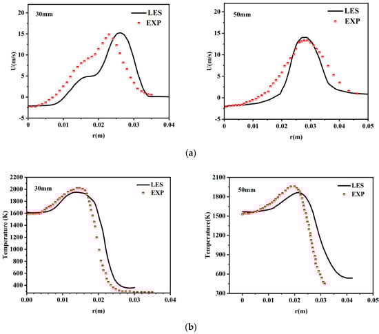
Figure 4.
(a) Radial velocity profiles at two axial heights; (b) radial temperature profiles at two axial heights.
3. Results and Discussion
3.1. Flame Observation
Because the burner is operated at a fixed power input and equivalence ratio, the total air flowrate changes slightly in different XNH3 cases, which produces an inlet velocity of ~2.1 m/s and ~1.8 m/s in the annular swirling channel for FP and NP modes. Figure 5 shows the NH3/CH4 cofiring flame images of various XNH3 fuel mixtures under the two different combustion modes. With the increase in XNH3, the flame color gradually turns from light blue to orange and the flame size keeps growing in both modes. In the FP mode, the flame maintains a “V” shape until XNH3 exceeds 70%, where obvious corner flame starts to occur in the outer recirculation zone, and the flame turns into an “M” shape. In the NP mode, none of the images show an “M“-shaped flame despite the swirling and bluff-body stabilized burner being used. The main reason is due to the offset of the tangential momentum of the outer air flow by the central fuel jets from the horizontal direction. With the increase in XNH3, the fuel jetting velocity from the eight diffusers increases, thus the flame is extruded towards the sidewall, and the flames are kept in a “V” shape.

Figure 5.
Variation in flame images against XNH3 in (a) FP mode and (b) NP mode. The symbol of * means this species is a radical.
In the FP mode, the main flame above the burner exhibits a uniform color regardless of XNH3, indicating a homogeneous burning of the NH3/CH4 mixture. However, in the NP mode, the flame is seen to be divided into two parts, which is more obvious for mixtures with XNH3 ranging from 10% to 60%. Specifically, an orange NH3 flame appears in the central region and it is surrounded by a light blue CH4 flame on the outside. This phenomenon is called “flame stratification” hereafter.
The flame stratification that happens in the NP combustion mode for moderate XNH3 conditions is caused by the different chemical characteristics between CH4 and NH3. In the NP mode, as the NH3/CH4 mixture moves towards the outer swirling air, CH4 ignites faster than NH3 owing to its lower ignition energy and higher laminar flame speed and, subsequently, O2 in the shear layer is consumed by CH4, thus forming the surrounding CH4 flame. The CH4 flame blocks the diffusion of O2 from the outer into the center near the burner root, thus NH3 undergoes thermal decomposition due to O2 deficiency. Because of the expansion of the CH4 flame towards the sidewall, flue gas recirculation takes place in the center at a higher location, which contains sufficient O2 and heat for the ignition of NH3 and its decomposition species.
The flame stratification gradually becomes less obvious as XNH3 increases. This is because on one hand, more O2 in the outer swirling air can react with NH3 due to the reduced CH4 flowrate; on the other hand, the horizontal velocity of the fuel from the diffusers becomes larger due to the lower mixture heating value, thus the mixing between fuel and outer swirling air can be facilitated, which can be confirmed by the gradual disappearance of the central NH3 flame in larger XNH3 conditions.
Furthermore, according to the distribution images of CH and NH2 radicals under the condition of XNH3 = 50% in the right figure, it can be observed that in the FP mode, due to the uniform mixing of CH4 and NH3 and their synchronized ignition, the distribution regions of CH and NH2 are highly overlapping. In contrast, in the NP mode, as CH4 ignites first due to its lower ignition temperature, the subsequent ignition of NH3 is triggered through the inward heat transfer and outward diffusion of NH3, resulting in a spatial structure where CH radicals are distributed in the outer layer and NH2 radicals are concentrated in the inner region.
3.2. NO Emission Measurement and Prediction
As mentioned earlier, five candidate mechanisms are considered for predicting the NO emission performance for NH3/CH4 cofiring flames. In this regard, LES modeling is first conducted for the FP mode in all XNH3 conditions. The comparison of the predicted NO profiles from the five mechanisms against the measurements is shown in Figure 6. According to the measurement, NO emission first increases and then decreases with XNH3, and this trend is captured by all considered mechanisms. In addition, the inflection point of XNH3 of 50% is also predicted by the mechanisms except for the Sun model, which generates the maximum NO emission at XNH3 of 40%.
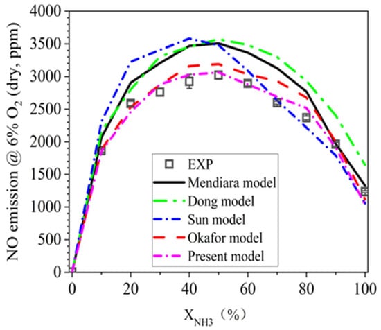
Figure 6.
NO predictive performance of five NH3/CH4 mechanisms for FP flames.
Figure 6 also indicates that, the models of Mendiara et al., Dong et al. and Sun et al. would overpredict the NO emission, especially in moderate XNH3 conditions. Okafor’s model has a much better performance than the aforementioned three candidates, but it still overpredicts the NO emission in the XNH3 range of 40~80%. As the present model is modified based on the Okafor’s model by updating the key C-N interaction reactions, which has been described in our previous work, the present model is found to satisfactorily predict the NO emissions in all XNH3 conditions.
As a further validation trial, LES modeling is also performed for all NH3/CH4 blends in the NP mode using the present model, and the comparisons of NO emission between the measurement and prediction in the two combustion modes is shown in Figure 7. As can be observed, the NP mode exhibits a similar NO profile as the FP mode, and NO emission also reaches its peak at XNH3 of 50%. This value is well predicted by the LES. Moreover, the NO prediction error of the NP flames is estimated to be below 10%, suggesting the high reliability of the present model.
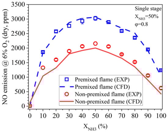
Figure 7.
NO emission predictions for FP and NP flames using the present NH3/CH4 mechanism model.
Figure 7 also indicates a lower NO emission in the NP mode compared to the FP mode throughout the whole range of XNH3. The lower NO emission in the NP mode is considered to be related to the flame stratification effect. According to Figure 5, the flame stratification in the NP mode first becomes stronger when XNH3 increases from 0% to 50%, and then becomes weaker as XNH3 further increases. This is in line with the NO reduction extent of the NP mode compared to the FP mode shown in Figure 7.
The aforementioned study found that NO emissions in the NP mode are lower than those in the FP mode. This phenomenon may be attributed to incomplete combustion of a portion of NH3, which escapes to the rear section of the combustor and undergoes pyrolysis, producing N2 and H2. To investigate whether increasing the residence time of NH3 in the combustor could improve the burnout performance of NH3 in the NP mode, combustion experiments under the NP mode are conducted at different combustor heights.
Figure 8 illustrates the variation in H2 emissions at the outlet with increasing XNH3 under different combustor heights (H). The results indicate that, under all H conditions, H2 emissions are detected at the combustion chamber outlet when XNH3 > 20%. Additionally, higher combustor heights corresponded to lower H2 emissions and higher NO emissions. When XNH3 < 60%, the influence of combustor height on NO emissions is minimal. This suggests that increasing the combustion chamber height only provides limited improvement in burnout performance under high XNH3 conditions, and NH3 pyrolysis still occurs within the combustor. Therefore, to enhance the burnout performance in the NP mode, merely extending the fuel residence time is insufficient; it must be combined with other measures, such as enhanced mixing.
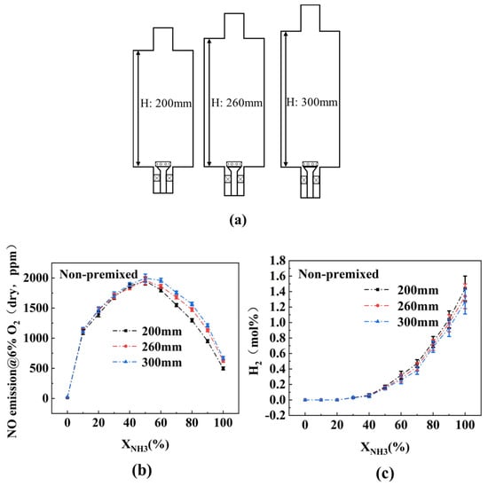
Figure 8.
(a) Combustor at different heights; (b) effect of combustor heights on NO emission in NP mode; (c) effect of combustor heights on H2 emission in NP mode.
3.3. NO Reduction Mechanism of NP Flame
In order to gain a deeper understanding of the NO reduction mechanism for the NP flame, the LES modeling results of mean temperature and major species concentrations on the combustor central plane are compared for 50% XNH3 mixture between the two combustion modes, as shown in Figure 9 and Figure 10. The OH maps indicate that the fuel combustion mainly happens on the shear layer in the FP mode, while additionally occurring in the downstream central region. In both modes, the high NO region basically overlaps with the high OH region, which suggests the strong correlation between OH radical and NO formation, as also reported in previous studies [13,14]. However, despite the relatively higher OH concentration, NO concentration in the outlet is smaller in NP mode. The main reason is due to the reduced NO formation in the central upstream region, where a relatively low OH concentration is also presented.
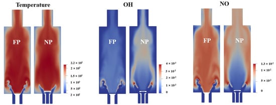
Figure 9.
LES modeling results of temperature, OH concentration and NO concentration in 50% XNH3 for FP mode and NP mode on the central combustor plane.
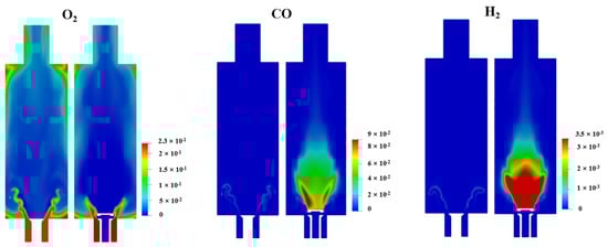
Figure 10.
LES modeling results of O2 concentration, CO concentration and H2 concentration in 50% XNH3 for FP mode and NP mode on the central combustor plane.
As explained in Section 3.1, the central low OH region in the NP mode is a result of the flame stratification effect. According to Figure 10, in the shear layer, a part of CH4 consumes O2 from the outer swirling air prior to NH3. Due to the deficiency of O2, a large amount of CO is formed by the partial oxidation of CH4, and H2 is formed by the thermal decomposition of NH3. To enhance the comparison, Figure 11 shows the radial concentration curves for O2, H2 and CO 20 mm above the burner exit. Obviously, O2 is maintained at 4% in the center in FP, owing to the inner flue gas recirculation. Such an atmosphere indicates the major NH3 consumption route via oxidation. Contrarily, the central fuel-rich atmosphere implies a strong thermal decomposition route of NH3 consumption in NP. This is considered to be the underlying reason for the lower NO emission in NP compared to the FP counterpart.
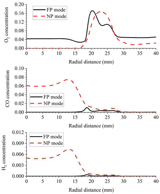
Figure 11.
LES modeling profiles of O2 concentration, CO concentration and H2 concentration in 50% XNH3 for FP and NP modes at 20 mm above the burner exit.
4. Conclusions
An ammonia/methane cofiring experiment was carried out by varying XNH3 from 0% to 100% in both fully premixed (FP) and non-premixed (NP) combustion modes. The FP flames show a continuous appearance with a uniform color, demonstrating a homogeneous combustion nature. However, the NP flames show two separated tongues with different colors, especially in moderate XNH3 conditions. Such a flame stratification phenomenon is responsible for the lower NO emission in the NP mode under all XNH3 conditions.
LES modeling following the present experiment has also been conducted. Five NH3/CH4 combustion mechanisms are tested in terms of their predictive reliability for NO emission. Among them, the present model is found to perform better and to satisfactorily predict the NO emission profiles over the whole XNH3 range for both FP and NP flames.
According to the LES modeling result, flame stratification in the NP mode is caused by the reaction sequence of the fuel components with the outer swirling air. Specifically, CH4 burns faster than NH3 and it consumes the O2 in the shear layer, generating a strong fuel-rich region in the center. As a result, CH4 and NH3 undergo partial oxidation and thermal cracking in the center, respectively. Compared to the fully oxidation route in the FP mode, a large part of NH3 is consumed through thermal cracking and converted to H2 and N2. This creates a large low-NO region in the combustor center and the final NO emission is then substantially reduced.
In the NP mode, insufficient fuel-air mixing along with fuel pyrolysis occurs. Therefore, in practical gas turbine combustors and boilers, it is necessary to enhance the swirl intensity of the air to achieve better mixing, while staged combustion can be adopted to consume the combustible products generated from pyrolysis.
Author Contributions
X.J.: investigation, writing—original draft preparation. Q.X.: validation, formal analysis. Z.L.: investigation, software. A.F.: funding acquisition, supervision, writing—review and editing. All authors have read and agreed to the published version of the manuscript.
Funding
This research was funded by the Research Project from Electric Power Research Institute, State Grid Xinjiang Electric Power Co., Ltd., China (Grant number: SGXJDK00NYJS2400358).
Data Availability Statement
The original contributions presented in this study are included in the article. Further inquiries can be directed to the corresponding author.
Conflicts of Interest
Authors Xuehui Jing, Qiang Xu were employed by the company State Grid Xinjiang Electric Power Co., Ltd. The remaining authors declare that the research was conducted in the absence of any commercial or financial relationships that could be construed as a potential conflict of interest. The authors declare that this study received funding from State Grid Xinjiang Electric Power Co., Ltd. The funder was not involved in the study design, collection, analysis, interpretation of data, the writing of this article or the decision to submit it for publication.
Abbreviations
The following abbreviations are used in this manuscript:
| FP | Fully premixed |
| NP | Non-premixed |
| LES | Large-eddy simulation |
| XNH3 | NH3 volumetric fraction in the binary fuel mixture |
| TDLAS | Tunable diode laser absorption spectroscopy |
References
- Kojima, Y.; Yamaguchi, M. Ammonia as a hydrogen energy carrier. Int. J. Hydrogen Energy 2020, 47, 22832–22839. [Google Scholar] [CrossRef]
- Li, C.; Hao, Q.; Zhang, W.; Wang, S.; Yang, J. Development strategies for green hydrogen, green ammonia, and green methanol in transportation. Renew. Energy 2025, 246, 122904. [Google Scholar] [CrossRef]
- Shy, S.S.; Mai, V.T.; Chen, Y.R.; Hsieh, H.Y. Nanosecond repetitively pulsed discharges and conventional sparks of ammonia-air mixtures in a fan-stirred cruciform burner: Flammability limits and ignition transition. Appl. Energy Combust. Sci. 2023, 15, 100164. [Google Scholar] [CrossRef]
- Kobayashi, H.; Hayakawa, A.; Somarathne, K.K.A.; Okafor, E.C. Science and technology of ammonia combustion. Proc. Combust. Inst. 2019, 37, 109–133. [Google Scholar] [CrossRef]
- Imamura, T.; Nakamura, Y.; Hayashi, K.I.; Hosaka, D.; Suematsu, J.I. Experimental study on effect of inert gas dilution for flammability of NH3/O2 mixtures. Proc. Combust. Inst. 2024, 40, 105308. [Google Scholar] [CrossRef]
- Li, T.; Duan, Y.; Wang, Y.; Zhou, M.; Duan, L. Research progress of ammonia combustion toward low carbon energy. Fuel Process. Technol. 2023, 248, 107821. [Google Scholar] [CrossRef]
- Hayakawa, A.; Arakawa, Y.; Mimoto, R.; Somarathne, K.K.A.; Kudo, T.; Kobayashi, H. Experimental investigation of stabilization and emission characteristics of ammonia/air premixed flames in a swirl combustor. Int. J. Hydrogen Energy 2017, 42, 14010–14018. [Google Scholar] [CrossRef]
- Khateeb, A.A.; Guiberti, T.F.; Wang, G.; Boyette, W.R.; Younes, M.; Jamal, A.; Roberts, W.L. Stability limits and NO emissions of premixed swirl ammonia-air flames enriched with hydrogen or methane at elevated pressures. Int. J. Hydrogen Energy 2021, 46, 11969–11981. [Google Scholar] [CrossRef]
- Zhang, M.; An, Z.; Wang, L.; Wei, X.; Jianayihan, B.; Wang, J.; Huang, Z.; Tan, H. The regulation effect of methane and hydrogen on the emission characteristics of ammonia/air combustion in a model combustor. Int. J. Hydrogen Energy 2021, 46, 21013–21025. [Google Scholar] [CrossRef]
- Wei, X.; Zhang, M.; Wang, J.; Huang, Z. Investigation on lean blow-off characteristics and stabilization mechanism of premixed hydrogen enhanced ammonia/air swirl flames in a gas turbine combustor. Combust. Flame 2023, 249, 112600. [Google Scholar] [CrossRef]
- Somarathne, K.D.K.A.; Colson, S.; Hayakawa, A.; Kobayashi, H. Modelling of ammonia/air non-premixed turbulent swirling flames in a gas turbine-like combustor at various pressures. Combust. Theor. Model. 2018, 22, 973–997. [Google Scholar] [CrossRef]
- Okafor, E.C.; Somarathne, K.K.A.; Hayakawa, A.; Kudo, T.; Kurata, O.; Iki, N.; Kobayashi, H. Towards the development of an efficient low-NOx ammonia combustor for a micro gas turbine. Proc. Combust. Inst. 2019, 37, 4597–4606. [Google Scholar] [CrossRef]
- Tu, Y.; Xu, S.; Liu, H. Combustion and emission characteristics of NH3/CH4/air in a model swirl combustor: Comparison between premixed and non-premixed modes. Int. J. Hydrogen Energy 2023, 48, 17311–17323. [Google Scholar] [CrossRef]
- Tu, Y.; Zhang, H.; Guiberti, T.F.; Avila Jimenez, C.D.; Liu, H.; Roberts, W.L. Experimental and numerical study of combustion and emission characteristics of NH3/CH4/air premixed swirling flames with air-staging in a model combustor. Appl. Energy 2024, 367, 123370. [Google Scholar] [CrossRef]
- Liu, Z.; Tu, Y.; Zhang, H.; Liu, H.; Luo, Z.; Zhang, S. Comparison of combustion, emission and flame stabilization characteristics for NH3/CH4 mixtures between premixed and non-premixed modes: A joint experimental and LES investigation. Fuel 2026, 405, 136797. [Google Scholar] [CrossRef]
- Yoshizawa, A. Statistical theory for compressible turbulent shear flows, with the application to subgrid modeling. Phys. Fluids 1986, 29, 2152–2164. [Google Scholar] [CrossRef]
- Correa, S.M. Models for high-intensity turbulent combustion. Comput. Syst. Eng. 1994, 5, 135–145. [Google Scholar] [CrossRef]
- Sabelnikov, V.; Fureby, C. Extended LES-PaSR model for simulation of turbulent combustion. Prog. Propuls. Phys. 2013, 4, 539–568. [Google Scholar] [CrossRef]
- Mendiara, T.; Glarborg, P. Ammonia chemistry in oxy-fuel combustion of methane. Combust. Flame 2009, 156, 1937–1949. [Google Scholar] [CrossRef]
- Dong, S.; Wang, B.; Jiang, Z.; Li, Y.; Gao, W.; Wang, Z.; Cheng, X.; Curran, H.J. An experimental and kinetic modeling study of ammonia/n-heptane blends. Combust. Flame 2022, 246, 112428. [Google Scholar] [CrossRef]
- Sun, J.; Yang, Q.; Zhao, N.; Chen, M.; Zheng, H. Numerically study of CH4/NH3 combustion characteristics in an industrial gas turbine combustor based on a reduced mechanism. Fuel 2022, 327, 124897. [Google Scholar] [CrossRef]
- Okafor, E.C.; Naito, Y.; Colson, S.; Ichikawa, A.; Kudo, T.; Hayakawa, A.; Kobayashi, H. Experimental and numerical study of the laminar burning velocity of CH4–NH3–air premixed flames. Combust. Flame 2018, 187, 185–198. [Google Scholar] [CrossRef]
- OpenCFD. The Open Source CFD Toolbox. User Guide; OpenCFD Ltd.: Berkshire, UK, 2009; p. 770. [Google Scholar]
- Qian, X.; Zou, C.; Lu, H.; Yao, H. Large-eddy simulation of Cambridge-Sandia stratified flames under high swirl. Combust. Flame 2022, 244, 112241. [Google Scholar] [CrossRef]
- Zhang, W.; Karaca, S.; Wang, J.; Huang, Z.; van Oijen, J. Large eddy simulation of the Cambridge/Sandia stratified flame with flamelet-generated manifolds: Effects of non-unity Lewis numbers and stretch. Combust. Flame 2021, 227, 106–119. [Google Scholar] [CrossRef]
- Liu, Z.; Tu, Y.; Zhang, H.; Liu, H.; Luo, Z.; Zhang, S.; Jiang, L. Large eddy simulation study on the effects of swirl number on dynamic combustion characteristics of stratified methane swirling flame. Energy 2025, 333, 137458. [Google Scholar] [CrossRef]
Disclaimer/Publisher’s Note: The statements, opinions and data contained in all publications are solely those of the individual author(s) and contributor(s) and not of MDPI and/or the editor(s). MDPI and/or the editor(s) disclaim responsibility for any injury to people or property resulting from any ideas, methods, instructions or products referred to in the content. |
© 2025 by the authors. Licensee MDPI, Basel, Switzerland. This article is an open access article distributed under the terms and conditions of the Creative Commons Attribution (CC BY) license (https://creativecommons.org/licenses/by/4.0/).