Abstract
Arc faults in low-voltage three-phase systems are a major hazard for both people and equipment, requiring extremely fast and selective protective measures. This paper presents the concept and simulation analysis of a hybrid arc eliminator that combines multi-section thyristor branches with a fast mechanical short-circuit device. The arc eliminator enables phase-selective arc suppression, ensuring that only the faulted phase is shunted while healthy phases remain in service. Simulations carried out in ATPDraw, supported by experimental reference data, demonstrate effective arc extinction within sub-millisecond to millisecond time scales across the range of inductances typically encountered in real circuits. This study analyzes the influence of circuit inductance on commutation dynamics and arc duration, as well as the distribution of conduction time among thyristor sections to balance thermal stress. A dynamic I2t-based control strategy is proposed to enhance reliability and component utilization, and preliminary perspectives on optimization supported by artificial intelligence are discussed. The results indicate that the arc eliminator can significantly improve personnel safety and equipment resilience, particularly in critical installations such as data centers, mining infrastructure, ships, or photovoltaic and electric vehicle systems.
1. Introduction
Arc faults represent one of the most serious threats in power systems. They are particularly dangerous in low-voltage networks, as these installations are commonly found in every person’s surroundings and are often operated by individuals without specialized electrical knowledge, who may be unaware of the severe consequences of an electric arc. Devices supplied from low-voltage (LV) 230/400 V networks—including distribution boards, busbar systems and industrial switchgear—routinely operate at prospective short-circuit currents of several kiloamperes. Under these conditions, an unintended breakdown of insulation may initiate an electric arc whose current is limited primarily by the source impedance and by the impedance of the fault loop. Even for relatively short fault paths, arc currents in the range of 1–10 kA and arc voltages of tens of volts are typical, which leads to high incident energy and severe thermal and mechanical stresses in the vicinity of the fault [1,2]. As a result, personnel and non-specialist users working on or near LV equipment are exposed to significant hazards (burns, pressure waves, molten metal), even though the nominal system voltage is below 1 kV.
An electric arc, which results from current flowing through ionized air, generates intense energy release, rapid temperature and pressure rise, and the emission of strong acoustic waves, with foundational analyses provided in [1], extended discussion in [2], and characterization of pressure effects in [3]. These phenomena often lead to severe damage of electrical equipment and pose a significant hazard to personnel located near the fault zone; comprehensive descriptions are given in [4], with additional experimental evidence of equipment damage in [5,6]. Prolonged exposure to an electric arc may cause critical injuries, including burns, eye damage due to ultraviolet radiation, and trauma from molten metal ejection, as reported in [7,8,9].
From a topological perspective, two main classes of faults can be distinguished in LV systems: single-phase arcs (typically between a phase conductor and protective earth or neutral) and multi-phase arcs involving two or three phases. In single-phase faults, the arc current is constrained by the impedance of a single-phase conductor and the return path, and the discharge is usually extinguished when the current naturally crosses zero and the arc column cools down. In three-phase faults, the presence of three phase-shifted voltages may sustain the discharge over several half-cycles, with re-ignition occurring in different phase paths. This leads to longer fault durations, higher electrodynamic forces, and more demanding selectivity requirements for protection devices [10,11]. These characteristics motivate protection schemes that are explicitly designed for phase-selective operation in three-phase LV networks.
Fast and effective extinguishing of electric arcs is therefore crucial for protecting life and health, as well as minimizing equipment damage [10,11]. The literature offers many methods for mitigating the effects of arc faults, including fuse links, fault current limiters, and fast mechanical and semiconductor circuit breakers, with representative implementations reported in [12,13,14]. However, traditional methods often exhibit insufficiently fast response times or limited effectiveness at low fault current levels, as noted in [15,16].
In response to these limitations, innovative solutions based on semiconductor switches have been developed, such as hybrid switches that combine the advantages of mechanical and semiconductor technologies, as shown in [17], with a complementary design approach presented in [18] and implementation details with performance considerations reported in [19]. Hybrid switches using parallel-connected thyristor branches in conjunction with a fast mechanical switch enable near-instantaneous shunting of the protected circuit and effective arc extinguishing within a few milliseconds, as documented in [9], further device-level aspects are discussed in [17], and additional verification is provided in [20]. The high effectiveness of such hybrids in reducing arc duration and the associated thermal and mechanical hazards has been confirmed in prior studies, with system-level evidence in [20] and experimental assessment in [21]. However, these investigations were confined to single-phase systems, whereas three-phase systems dominate in industrial practice. To date, detailed analyses of hybrid-switch operation in three-phase networks remain limited, despite the added complexity introduced by three phase-shifted voltages, as noted in the general context in [12], with related three-phase considerations explored in [22], and extended case studies presented in [23,24].
The hybrid arc eliminator (AE) studied in this work consists of parallel-connected thyristor sections and a fast mechanical short-circuit device. In each phase, three thyristor sections are assigned to the positive half-cycle and three to the negative half-cycle of the supply voltage. Once an arc fault is detected by an external protection system, the AE controller triggers the appropriate thyristor sections so that the fault current is transferred from the arc to a low-resistance semiconductor path within hundreds of microseconds. Subsequently, a fast mechanical short-circuit device closes within several milliseconds and permanently takes over the current from the thyristors. In the three-phase architecture considered here, one single-phase AE is connected between each phase and protective earth (PE), which enables phase-selective extinction of the arc in the faulted phase while the two healthy phases remain in operation.
Building on the above considerations, this article addresses the limited prior analyses of hybrid-switch operation in three-phase low-voltage networks by investigating the application of a hybrid arc eliminator (AE) in such systems. In the first stage of the research, numerical simulations of the AE’s operation are conducted using ATPDraw software (version 7.5) under various fault conditions. In the second stage, the simulation results are partially verified experimentally. Due to the high cost of constructing a full-scale three-phase AE—comprising a total of 36 thyristors and 3 independently controlled mechanical switches—the experimental stage is therefore preceded by a simulation-based analysis. If the obtained results confirm the effectiveness of arc fault elimination using the proposed AE architecture, the construction of a physical test circuit is planned, with its structural details and experimental results to be presented in a separate publication.
In contrast to prior single-phase studies (see [17] for a representative hybrid-switch concept, [18] for a complementary design approach, [19] for implementation details and performance considerations, and [20] for a system-level assessment) this article contributes by:
- Analyzing the application of the AE in a three-phase LV network with phase-selective arc extinction in the faulted phase, i.e., only the affected phase is shunted while the two healthy phases continue to operate.
- Conducting a parametric investigation of the influence of series inductance on commutation and arc extinction time over a wide range (1–426 µH), including the observation of trend stabilization for L > 100 µH.
- Discussing sequential thyristor branch control that shortens the conduction time of each section while maintaining I2t limits.
- Presenting integration guidelines for three independent AEs (inter-pole blocking logic and compatibility with different detection methods).
Together, these contributions advance the single-phase concept toward a practical three-phase architecture, providing concrete design guidelines for implementation.
The proposed hybrid arc eliminator is particularly relevant in low-voltage switchgear supplying sensitive loads such as data centers, process lines, mining installations, ships, and PV/EV systems. As a complementary solution to conventional circuit breakers and detection systems, it reduces arc duration to below 1 ms and significantly limits the incident energy. This is important from the perspective of occupational safety requirements and the selection of personal protective equipment (PPE), as well as for maintaining power supply continuity, since phase-selective operation minimizes the extent of outages and related damage.
Beyond the earlier hybrid and semiconductor-based approaches, recent studies have focused on active arc-energy reduction using high-speed quenching units coordinated with optical and current detection, reporting substantial reductions in incident energy in practical deployments. A dedicated product standard for active arc-fault mitigation systems (IEC 60947-9-2) has been published, formalizing test methods and performance criteria for low-voltage assemblies [25]. In parallel with these hardware advances, the literature shows rapid progress in data-driven arc-fault detection for low-voltage AC systems, with lightweight models designed for implementation on microcontrollers [26] and on embedded edge devices [27,28]. For example, Chen et al. [26] report a hybrid scheme that combines an Adam-optimized neural network with a hardware feature extractor, achieving real-time execution on an STM32-class MCU while maintaining competitive accuracy under diverse loads. Ning et al. [27,28] propose lightweight architectures tailored to AC arc-fault signatures and demonstrate high detection accuracy with reduced parameter counts, which is essential for embedded deployment. Beyond convolutional baselines, transformer-type sequence models have also been explored for AC series arc-fault detection, offering strong performance on challenging time-series datasets [29]. These trends point toward faster detection, fewer false trips, and practical on-device inference, which can complement fast arc-quenching hardware in integrated protection schemes, as evidenced in [26,27,28]. However, most recent contributions concentrate on detection or on single-phase scenarios, with limited analysis of coordinated, phase-selective mitigation in three-phase low-voltage networks. The present study addresses this gap by examining a hybrid arc eliminator with selective operation and by assessing dynamic conduction sharing under an I2t constraint. By relating device-level decisions to arc-extinction time and thermal load distribution, the study contributes design guidelines that are consistent with the emerging standardization landscape (IEC 60947-9-2) while extending prior single-phase concepts to a practical three-phase architecture [25].
Building on the need for sub-millisecond, phase-selective arc suppression emphasized in this introduction, the paper proceeds as follows. Section 2 presents the hybrid switch architecture together with the underlying modeling framework (including the Cassie-based arc model) and the simulation and measurement procedures. Section 3 integrates the results with discussion in four consecutive steps: validation in a single-phase setup, demonstration of phase selectivity in a three-phase system, study of the impact of series inductance, and evaluation of a dynamic I2t-based control scheme—followed by an outlook on AI-supported optimization. Section 4 concludes the work.
2. Materials and Methods
This section details the methodology used in this study. First, the hybrid arc eliminator (device under test) is described, followed by the three-phase network and test conditions, the Cassie-based arc model, and the simulation and measurement procedures. The content is presented in the order used to produce the results reported in Section 3, ensuring traceability and reproducibility.
2.1. Hybrid Switch Architecture
The hybrid switch is an advanced protective device that combines the advantages of semiconductor and mechanical technologies, providing exceptionally fast arc extinguishing in low-voltage circuits, as documented in [9], with a representative concept described in [17], implementation details discussed in [18], performance aspects analyzed in [19], and a system-level assessment presented in [20]. The device consists of thyristor sections connected in a parallel configuration and a fast mechanical switch. In this study, each phase conductor is equipped with a separate single-phase hybrid switch.
The hybrid switch does not include a built-in arc-fault detector. Instead, it relies on rapid external detection provided by appropriate systems, including optical detectors that register the arc flash [30], circuits that analyze sudden voltage drops [31], schemes that track sharp current surges [32], and combined or relay-based solutions used in industrial practice [33] and reported in recent implementations [34]. From the perspective of the hybrid arc eliminator, an important advantage is independence from the trigger type, because the system can be activated by an impulse from any arc-detection solution, which makes it highly versatile. As a result, the device can be integrated both with commercial protection systems—such as the Polish ZL-4 (SPIE Energotest sp. z o.o., Poland) system [35]—and with dedicated detection circuits developed for specific industrial applications.
When an electric arc is detected, the control system immediately generates a triggering signal for the thyristors and the fast mechanical switch, causing a rapid short-circuit of the protected circuit segment. Due to the low forward voltage of the thyristors connected in parallel with the circuit, the arc is instantly extinguished. Subsequently, after the arc is quenched, the fast mechanical switch is activated to take over the current from the thyristors, protecting the semiconductors against thermal damage. The thyristor branch extinguishes the arc in less than 1 ms [17], making the hybrid switch an exceptionally effective solution for protection against the effects of arc faults. Subsequently, the fast mechanical short-circuit device (MSCD) closes within several milliseconds to take over the current from the thyristors.
The main advantages of the hybrid switch include:
- A very short response time of less than 1 ms;
- Immediate arc extinguishing, which significantly reduces the energy released during the fault;
- Minimization of damage to power equipment and network infrastructure;
- Significant reduction in the and mechanical effects resulting from arc faults;
- Limitation of hot gas and metal fragment emissions, which increases the safety of people near the fault location.
These features have been experimentally confirmed in the authors’ previous works, which analyzed hybrid-switch operation under different low-voltage fault conditions [9], presented detailed measurements of arc extinction dynamics [17], evaluated thermal and mechanical effects [18], and verified overall system performance in a full-scale test setup [20].
The use of a hybrid switch in a three-phase system, where each phase has its own single-phase switch (AE), enables effective and independent arc fault extinguishing in all phase conductors, enhancing the safety and reliability of the entire power system.
Figure 1a shows that the AE hybrid eliminator consists of semiconductor thyristor branches (Th1–Th6) and a mechanical short-circuiting switch (MSCD) connected in parallel with them. The thyristors connected in parallel conduct current for the positive half-cycle (Th1, Th2, Th3) and the negative half-cycle (Th4, Th5, Th6). Each semiconductor branch contains an appropriate number of thyristors connected in series, allowing for the sequential takeover of the fault current and the gradual reduction in arc voltage below the level required to sustain the arc until the MSCD switch contacts are closed.
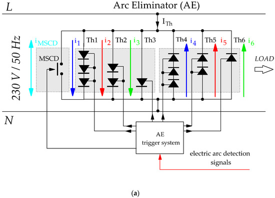

Figure 1.
Hybrid Switch (AE): (a) Schematic diagram of the single-phase arc eliminator (AE) using a hybrid short-circuit switch; (b) Time waveforms of currents flowing through successive branches of the AE.
At the moment an arc fault is detected, a signal is immediately sent to the microprocessor-based control system (AE trigger system). The task of the control system is to instantly activate the appropriate thyristor branches, starting with the one containing the highest number of thyristors and progressing to those with fewer. In the initial phase of the arc fault, the fault current flows through the thyristor section with the highest voltage drop. In the subsequent stage, the current is taken over by the thyristor sections with fewer semiconductor elements, which have a lower forward voltage drop, thereby minimizing energy losses.
After the fault current is taken over by the thyristor branches, the contacts of the mechanical short-circuit device (MSCD) close within the next few milliseconds. The function of this mechanical switch is to permanently take over the fault current from the thyristors, allowing them to be unloaded and the electric arc to be fully extinguished. Thanks to the low forward voltage drop of the thyristors, the contact-closing process of the mechanical switch occurs without the risk of arc formation at its contacts. Once the MSCD is closed, the fault current flows directly through the mechanical switch until the main circuit breaker operates.
Ultimately, after the arc is extinguished and the main circuit breaker is triggered, the hybrid eliminator is disconnected, and the electrical system is completely isolated from the fault location. Thanks to its rapid response and the use of thyristor branches supported by a mechanical switch, the AE effectively limits the energy released during the arc fault and minimizes its thermal, mechanical, and acoustic effects, thus ensuring a high level of safety for equipment and for people located near the disturbance area.
Figure 1b presents the current waveforms and the triggering signals for the thyristors and the mechanical switch in the multi-section arc eliminator (AE) solution. For example, if an arc fault occurs at time t = 0 and the detected polarity of the fault current is positive, the semiconductor sections are activated in the following sequence: Th1, Th2, Th3, followed by Th4, Th5, Th6, and then MSCD. These sections conduct the respective portions of current labeled as i1, i2, i3, followed by i4, i5, i6, and iMSCD. This procedure ensures smooth and controlled takeover of the fault current by the thyristor system, which maintains conduction until the mechanical switch MSCD closes. In this way, the eliminator operates almost instantaneously, with sequential discharge of its semiconductor branches and arc-free current transfer to a contact switch with negligible contact resistance.
The use of thyristors as commutation elements also enables precise control of their conduction time, regardless of the current waveform, which translates into improved performance parameters of the entire AE system. In the proposed configuration, which includes three parallel semiconductor sections per half-cycle of the supply voltage, conduction times can be programmed so that each section is loaded evenly. As a result, by shortening the conduction time of a given section to one-third of the standard duration (e.g., 10 ms), the allowable current in that section can be significantly increased—even up to three times—without exceeding the permissible value of the Joule integral. This strategy increases the current-carrying capacity of the entire system.
To simplify the complex diagrams in the three-phase solution and to facilitate understanding of the hybrid switch’s operating principle, in the following sections of the article, the AE device will be represented using the symbol shown in Figure 2. This symbol illustrates the basic structure of the hybrid switch, i.e., the parallel connection of a fast mechanical switch and a semiconductor branch represented by thyristors.

Figure 2.
Simplified equivalent circuit diagram of the hybrid switch (AE).
To highlight the novelty of the proposed hybrid arc eliminator (AE), Table 1 presents a comparison of selected protection solutions against arc faults in LV networks. The table summarizes four representative approaches: optical detection systems combined with a circuit breaker, arc fault detection devices (AFDD), crowbar/busbar shorting circuits, and the proposed AE. Each solution is characterized in terms of its operating principle, typical reaction time, phase selectivity, and major limitations.

Table 1.
Comparison of selected arc fault protection solutions in LV systems [1,7,11,14,15,17,19,20].
As shown in Table 1, conventional solutions such as optical detectors or AFDDs rely on circuit breaker operation and therefore exhibit relatively long reaction times (10–100 ms). Crowbar systems offer a faster response (1–3 ms), but usually without full phase selectivity, which limits their applicability in three-phase networks. In contrast, the proposed hybrid AE achieves sub-millisecond response, ensuring both significant reduction in arc duration and incident energy, and phase-selective operation—the AE extinguishes the arc only in the affected phase, while the remaining phases continue to operate normally. This minimizes the scope of disconnections at the system level, although all loads connected to the faulted phase are still temporarily interrupted. In this way, the AE complements traditional detection and breaker systems.
The comparison of arc extinction times shows that the proposed AE architecture can provide unique benefits, combining ultra-fast arc suppression with selective operation, which makes it a highly promising option for sensitive or critical installations.
2.2. Research Assumptions
2.2.1. Research Objective
The aim of this study is to analyze the performance of a proprietary hybrid switch solution in a three-phase low-voltage network. In prior single-phase investigations, Nowak et al. [9] documented the operating principle and experimental behavior, provided detailed analyses of arc extinction and device operation [17], reported laboratory validation across representative fault scenarios [18], and demonstrated application in a practical setup [20]. A related contribution by L. Kumpulainen, J. A. Kay, and M. Aurangzeb [19] offers an additional perspective on hybrid protection concepts.
The research presented in this paper focuses on three key areas. First, the effectiveness of ground arc fault elimination in three-phase networks using the hybrid switch is analyzed. Second, the impact of AE switch activation on the time waveforms and amplitudes of fault currents in individual phases is assessed, with particular emphasis on the dynamics of the commutation process. The third area of the study involves analyzing the effect of the series inductance value on the effective arc extinguishing time, which allows for determining the optimal operating conditions of the protection system.
2.2.2. Research Methodology
The planned research will be carried out in two stages. In the first stage (which is the subject of this article), computer simulations will be conducted using the advanced simulation software ATPDraw, allowing for an analysis of the hybrid switch operation in a three-phase network. In the second stage (which will be the subject of a follow-up article), if the results of the first stage confirm the expectations for the hybrid switch, an experimental verification of the obtained simulation results will be performed. The first stage of preliminary research is necessary because the use of the AE arc eliminator in three-phase networks involves specific costs, resulting from the complexity of the thyristor system and the need for precise control of each semiconductor branch and mechanical switch, whose quantity must correspond to the type of fault being handled. Additionally, the sensitivity of semiconductor components to sudden overvoltages must be taken into account. Nevertheless, investing in the AE can bring significant economic benefits, mainly by reducing the energy released during arc faults, which, in turn, lowers the thermal and mechanical stress on conductors and equipment. This may allow for the optimized design of auxiliary components (e.g., lighter switchgear structures or protective housings), while the selection of conductor cross-sections must still comply with applicable standards based on continuous and short-circuit current ratings. The parameters of the modeled network and the arc model used during the simulations are presented in Table 2.
Table 2.
Test circuit parameters used in the simulation.
The rated source voltage of 400 V and frequency of 50 Hz correspond to a standard three-phase distribution network. The peak arc-current range of 1200–1600 A represents typical prospective fault currents in industrial LV boards with short fault loops, for which earlier measurements are available. The nominal arc voltage of about 70 V follows from (2) for an arc gap of 35 mm and a current of approximately 1.4 kA; the 35 mm gap length corresponds to the spacing between copper busbars in the tested switchgear. The Cassie time constant τ = 0.5 ms was selected as a representative mid-range value for arcs in air reported in the literature, balancing faster (≈0.5 ms) and slower (≈1.5 ms) decay cases. The steady-state arc resistance in the range 0.001–0.1 Ω results from the Cassie formulation and reflects the strong nonlinearity of the arc, which initially behaves as a very low-impedance path and gradually increases its resistance as the current decays. The AE activation delay of 0.2 ms aggregates the detection time and the response of the thyristor gate-drive circuitry and is consistent with timing measurements from previous single-phase experiments. The MSCD operating time of 10 ms reflects the closure time of the ZZ15 mechanical short-circuit switch used in the laboratory setup, whereas the 60 ms opening time of the main circuit breaker represents typical values specified for LV breakers under short-circuit conditions. Together, these assumptions ensure that the simulated conditions closely match a practical LV installation while still enabling parametric studies such as the inductance sweep reported in Section 3.
2.2.3. Three-Phase System Modeling
Figure 3 presents a simplified diagram of the analyzed power network along with the AE used for fault studies and simulation of the hybrid switch operation (AE—Arc Eliminator). The presented solution assumes that each phase is equipped with an AE connected between the phase conductor and the protective earth (PE). This architecture provides phase selectivity: upon arc detection, only the faulted phase is shunted to PE and extinguished, while the two healthy phases continue to operate. Note that this is not feeder-level selectivity—all loads supplied from the faulted phase are momentarily disconnected. For completeness, a feeder-level placement (local shunt directly across the faulted outgoing feeder/compartment) could maintain supply to other feeders on the same phase; this variant is outside the scope of the present model and is left for future work. The present study therefore focuses on phase-selective AE operation, in which only the faulted phase is shunted to PE, while feeder-level selectivity remains the responsibility of upstream protection devices (breakers and fuses).

Figure 3.
Diagram of a three-phase power supply network: each phase is equipped with an AE connected between phase and protective earth (PE). Phase-selective architecture (not feeder-selective). The yellow lightning symbols indicate the location of the arc fault in each phase conductor.
In the analyzed three-phase system, phases L1, L2, and L3 represent three current paths supplied by voltages denoted as u1(t), u2(t), and u3(t), respectively, each shifted by 120° in accordance with the classical definition of a symmetrical system. In the supply path, above the fault point, there are resistive-inductive elements labeled as R and L, which represent the fault loop impedance and may include additional components that limit the fault current. For each phase, an independent AE arc eliminator is provided, connected in parallel to the load. The load in each phase is modeled as a load impedance ZLOAD.
2.2.4. Arc Model
Voltages and currents measured during arc discharges are often highly complex and multifaceted. Numerous “black box” models have been developed to characterize them. Digital simulation of these arc models makes it possible to analyze arc properties without conducting real experiments involving high-current discharges. A well-established program used for such simulations is ATPDraw, which integrates a graphical circuit editor with waveform plotting tools. An introductory overview of the ATP/EMTP framework and the ATPDraw interface is given in [36]. Application-oriented examples relevant to low-voltage transient studies are presented in [37]. Modeling guidelines and user documentation are summarized in [38]. Recent case studies employing ATPDraw for arc-related transients are reported in [39].
In the present work, the arc model is based on the Cassie model. Equation (1) defines the method for determining arc conductance according to the Cassie model [40,41]:
where
G—arc conductance (S);
τ—arc time constant (s);
u—instantaneous arc voltage (V);
uc—average arc voltage (V).
The model assumes that power losses in the arc are constant and arise from deformation processes as described in [42]. It also assumes a nearly constant arc voltage used to represent the arc during most of the current-conduction interval, with supporting discussion in [40]. In this framework, Equation (2) enables a rapid estimation of the arc voltage from two parameters: arc length (in millimeters) and arc current (in kA). A practical formulation of this relationship is provided in [41].
where
d—arc length (mm);
I—arc current (kA).
Equation (2) is used in simplified technical and engineering analyses, particularly under low-voltage conditions, where a quick estimation of arc voltage is important without the need to apply complex physical models. Its simplicity allows for easy consideration of the influence of geometric and current parameters on arc voltage [38,39].
The time constant of the electric arc (τ) is an important parameter describing the dynamic response of the arc to current variations. It determines the inertia with which the arc reacts to momentary changes in current and governs the time required to extinguish the arc after the circuit is interrupted. Representative values reported for copper electrodes in air place τ in the range of approximately 0.5–1.5 ms, as summarized in [40], with additional data in [41] and supporting discussion in [43].
In ATPDraw, an electric arc can be represented as a time-varying resistance (R(TACS) type 91) or as a time-varying voltage source (TACS Source). Such a time-varying element is defined using the MODEL block, with usage examples in [44], implementation notes in [45], application cases in [46], and complementary guidance in [47]. The MODEL computes the updated value at each iteration and can read circuit voltages or currents as inputs. The language and syntax for coding these models are specified in the ATPDraw Rule Book [48]. Figure 4 shows the Cassie arc model used in this study.

Figure 4.
Schematic implementation of the Cassie arc model in ATPDraw (based on the formulation given in [40,41]). The Cassie block calculates the time-varying arc conductance Garc(t) from the instantaneous arc voltage uarc and current iarc.
Figure 5 presents a model of a single-phase arc eliminator (AE), developed in the ATPDraw simulation environment. This solution can be easily adapted to three-phase systems by using three independent AE modules—one for each phase. The system structure includes an AC voltage source (labeled as Power supply), representing a single-phase low-voltage network. The semiconductor section consists of six thyristors (Th1–Th6), connected in three antiparallel pairs and arranged in parallel. This configuration allows for current conduction regardless of voltage polarity, thus ensuring effective AE operation during both the positive and negative half-cycles of the supply voltage. In the ATPDraw implementation, the thyristors are modeled as ideal controlled valves (VALVE elements with defined on/off conductances) without assigning a specific commercial device type; the results are therefore interpreted for generic medium-power SCRs with a nominal RMS current on the order of 1000 A and adequate surge-current capability, representative of devices typically used in LV protection applications.

Figure 5.
Hybrid switch model in the single-phase configuration.
The thyristor control system is implemented using components from the TACS library. Gate pulses are generated by Pulse-23 modules, which enable precise control of the switching time of individual thyristors according to the defined simulation conditions. This approach allows for the realistic representation of the arc fault detection process and the AE’s response. The mechanical part of the system is represented by the MSCD, modeled as a switching element of the TSWITCH type. Its operation corresponds to that of a real mechanical switch, with a user-defined closing time.
In the load branch, an electric arc model is placed, based on the Cassie equations (MODEL Cassie). This model accounts for the dynamic changes in arc voltage and current, as well as the possibility of re-ignition under certain conditions. Variables such as ignition voltage, arc length, and time constant can be adjusted to match the characteristics of the tested system. The load is implemented as an impedance (ZLOAD), which allows for the analysis of arc fault impacts on a realistic system load.
2.2.5. ATPDraw Environment and Simulation Workflow
ATPDraw serves as a graphical interface for the ATP/EMTP (Alternative Transients Program) solver, which integrates the network equations using the trapezoidal rule and supports event-driven switching. Circuit elements are placed and parameterized within ATPDraw, while control and measurement blocks are implemented using TACS/MODELS. An introductory overview of the ATP/ATPDraw environment is provided in [36] and a practical toolchain description is given in [37]. Modeling guidelines relevant to low-voltage transient studies are summarized in [38] and user documentation details are compiled in [39]. Usage notes for TACS/MODELS are discussed in [45] and implementation examples are presented in [46]. Application-oriented cases are reported in [47] and the Rule Book conventions and syntax are specified in [48]. In this study, the electric arc is represented as a time-varying resistance (R(TACS) type 91) controlled by a MODEL based on the Cassie arc formulation (Figure 4). The thyristor branches are triggered by Pulse-23 blocks, and the mechanical short-circuit device is represented by the TSWITCH element (Figure 5).
Simulations are carried out with a fixed time step of 1.0 µs to capture transient states such as arc ignition, AE activation, and MSCD closure. Default EMTP companion models are used for linear R–L elements. Switches employ standard conductance values in the on and off states. Initial conditions are set by steady-state initialization at 50 Hz before the fault occurs. Faults are introduced by scheduling the arc ignition at a specified moment (e.g., t = 12.8 ms in Section 3.1), after which the Cassie MODEL updates the conductance G(t) at each time step based on the local voltage u(t) and current i(t).
The model and parameter settings were verified by comparing AE operating times for single-phase waveforms with experimental reference data reported in previous works [9,17,18,19,20]. Despite small simulation deviations resulting from the simplified arc model, the overall measured trends are consistent with experimental results.
3. Results and Discussion
3.1. Arc Eliminator in a Single-Phase Circuit
This subsection validates the operating principle of the hybrid arc eliminator in a single-phase circuit, using the device description and the Cassie-based arc model defined in Section 2. The thyristor triggering sequence follows the scheme specified there.
Figure 6 illustrates the simplified operating principle of a hybrid switch for a single phase. Figure 6a shows the situation in which an electric arc has ignited. The flowing arc current iarc and arc voltage uarc reach values sufficient to sustain the discharge phenomenon. Although the arc voltage is lower than the supply voltage, its presence poses a threat to both people and equipment. Thanks to arc fault detection and the appropriate design of the AE switch (arc eliminator), one of the thyristor branches is triggered, enabling the current to be immediately taken over by this circuit.


Figure 6.
Simplified operating principle of the hybrid switch for a single phase: (a) Current and voltage during electric arc ignition; (b) Current and voltage during AE operation. The colored arrows indicate the current paths and their directions, while the yellow lightning symbol denotes the location of the arc fault.
Figure 6b depicts the state after the AE hybrid switch has been activated—the arc current iarc drops to zero, and the arc voltage disappears as well (uarc = 0 V). The current from the power supply is then redirected through the arc eliminator and denoted as iAE. For simplification, it is shown as a single current, although in reality—as demonstrated in work [20]—it is the sum of the currents flowing through individual branches of the eliminator (i1 + i2 + i3 and i4 + i5 + i6 + iMSCD). However, this simplification is not incorrect, since the sum represents the total current drawn from the power source and shows no dips or interruptions.
The experimental verification of the hybrid switch was presented in a series of single-phase studies by Nowak et al. [9], who documented the operating principle and arc-extinction behavior, provided detailed laboratory measurements under representative fault conditions [17], reported device performance with thermal and mechanical considerations [18], and demonstrated a practical setup with system-level assessment [20]. A complementary perspective was offered by L. Kumpulainen, J. A. Kay, and M. Aurangzeb [19], who discussed related hybrid protection concepts and implementation aspects. Building on this experimental evidence, the present section focuses on validating the arc model in the ATPDraw environment. Because real current and voltage waveforms from the experiments are available, they can be compared with the simulation outputs to assess how well the adopted model reproduces the observed phenomena.
Figure 7a–c presents the time waveforms of the source current i(t), arc current ia(t), arc voltage ua(t), and current in the arc eliminator branch (ith + iMSCD). The analysis concerns a single phase L1 in which an arc fault has occurred. To evaluate the correctness of the electric arc model based on the Cassie equations, the experiment was divided into four clearly defined stages.
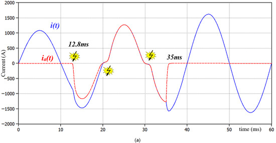

Figure 7.
Time waveforms of voltages and currents before arc ignition, during arc burning, and after AE activation: (a) Supply current i(t), arc current ia(t); (b) Supply voltage u(t), arc voltage ua(t); (c) Sum of thyristor currents iTh(t), mechanical switch current iMSCD(t).
The first stage includes the operation of the circuit under nominal conditions (time range from 0 ms to 12.8 ms), in which the system operates stably, without disturbances. In the second stage (12.8 ms–35 ms), the electric arc ignites, resulting in a change in the current’s characteristics and the appearance of voltage across the arc branch. The third stage (from 35 ms) is the phase in which the AE is activated and takes over current conduction, leading to arc extinction. The fourth stage (from 45 ms) covers the period in which the contacts of the mechanical switch close, and the entire load current flows through that switch. As a result, the semiconductor part of the AE is deactivated, and the system awaits the operation of the main circuit breaker.
It should be emphasized that the moment of arc ignition at t = 12.8 ms is arbitrary. This value was chosen to facilitate a detailed dynamic analysis of the phenomenon.
Up to t = 12.8 ms, the system remains in a steady state. The supply current i(t) (Figure 7a) reaches a peak value of approximately 1080 A, corresponding to the rated value. At t = 12.8 ms, the arc fault is initiated, leading to dynamic changes in circuit operation. In Figure 7a shows the appearance of the arc current ia(t), which gradually increases, reaching a peak of about 1275 A. Notably, the arc develops naturally uninterrupted by protection devices-and its current persists even after passing through zero, which is typical when conditions favor re-ignition.
Figure 7b shows the supply voltage u(t) and arc voltage ua(t). After arc initiation (t = 12.8 ms), the arc voltage remains significantly lower than the supply voltage (ranging from about 50 V to 80 V). It is worth noting that although the arc temporarily extinguishes (t ≈ 20 ms, current zero crossing), it reignites in the next half-cycle (t ≈ 21 ms), confirming that spontaneous arc extinction does not always mean permanent suppression. After the AE activates (t = 35 ms), the arc voltage drops to nearly zero, clearly indicating successful extinguishing.
In the analyzed case, the arc eliminator AE was activated at t = 35 ms. At the same time, gate pulses for the respective thyristor sections and the trigger signal for the mechanical switch are generated. In the simulation, a delay of 10 ms for the mechanical switch was assumed, resulting in its full closure at t = 45 ms. This deliberate delay in the operation of the thyristor–mechanical system aimed to illustrate the consequences of an arc fault in a system without a fast protective response.
After AE activation (Figure 7c), the current commutates to the thyristor branch iTh(t), which conducts from t = 35 ms to t = 45 ms, when the mechanical branch iMSCD(t) takes over conduction.
As a result of the current being taken over by the AE, the total impedance of the fault loop decreases-mainly because the device is installed as close as possible to the power source (e.g., in the main switchboard), placing it in a location with minimal circuit impedance. Consequently, the supply current increases to about 1625 A. This phenomenon must be considered at the design stage of the AE system-both the thyristors and current-carrying components, including conductors and protection devices, should be selected with a sufficient margin, accounting for temporary surges in fault current flowing through the AE branch.
These observations confirm the principle of operation and provide the baseline for three-phase tests in Section 3.2.
3.2. Arc Eliminator in a Three-Phase Circuit
Building on the single-phase verification, the analysis is extended to the three-phase power system defined in Section 2 to verify phase-selective operation and quantify the impact on healthy phases. Each phase conductor includes a 0.0508 mm2 copper fuse wire. The analysis aims to determine the time at which the wires in each phase melt under a defined fault current with a peak value of 1625 A, and then to evaluate the effectiveness of the hybrid switch (AE) in extinguishing the arc formed by the fuse melting. Because arc ignition occurs at different instants—depending on when each fuse reaches its energy threshold—the operation of the AE is phase-selective and the arc is extinguished independently in each phase.
In the analyzed model, each phase has a separate fuse wire installed independently. The simulation assumes the simultaneous application of phase voltage across all three phases. The instantaneous current in the three-phase sinusoidal system is defined as:
For the purposes of the analysis, the following assumptions were made:
- Cross-sectional area of the fuse wire: 0.0508 mm2;
- Length of the fuse wire: 0.035 m (35 mm);
- Fuse wires made of copper (resistivity ρ = 1.68 × 10⁻⁸ Ω·m);
- Resistance of each fuse wire: 0.0116 Ω;
- Fuse wires melt after exceeding an energy of 15 J (approximate value for a thin copper wire);
- Peak current per phase Imax = 1625 A;
- Frequency: 50 Hz;
- Short-circuit loop impedance per phase Z ≈ 0.2 Ω (where L = 1 µH → XL ≈ 3.14 × 10⁻⁴ Ω);
- Phase shift angle between current and voltage: φ = 0.09°;
- Arc voltage uc = 70 V (calculated based on (2));
- Arc time constant τ = 0.5 ms.
The above assumptions were chosen to match the geometry and parameters of the laboratory setup and a typical low-voltage network. The cross-sectional area and length of the fuse wire correspond to the actual copper fuse used in the experiments, and the melting energy of 15 J was estimated from its mass and the thermal properties of copper. The loop impedance and phase shift angle reflect a stiff LV supply with a short fault loop, while the characteristic arc voltage uc ≈ 70 V and time constant τ = 0.5 ms were selected within the ranges reported in the literature for arcs in air and fitted to previously measured waveforms. If a thicker fuse wire or higher loop impedance were assumed, the fault current and the time to reach the 15 J threshold would change—and a larger (or smaller) τ would, respectively, increase (or decrease)—the arc duration and energy. These variations would affect the quantitative values of currents and energies but would not alter the qualitative conclusions regarding the effectiveness of the proposed AE solution.
Joule energy losses can be determined by time integration of the power losses:
For each phase, the moment when the energy exceeded the threshold value of 15 J was calculated. The results are presented in Table 3.
Table 3.
Calculated arc ignition times (after exceeding 15 J of energy).
To accurately model the operation of the hybrid switch (AE), it was necessary to account for the total response delay time, which includes:
- The time required for reliable detection of the electric arc (e.g., detection of light flash, sudden current increase, or voltage drop);
- The response time of the thyristor triggering control system;
- The transition time of thyristors from blocking to conducting state.
The total delay time was set to 0.2 ms, reflecting the mean value obtained in the authors’ previous single-phase experiments and timing measurements [9,17,18,20].
Figure 8 shows the current waveforms of phase L1. At approximately t ≈ 2.6 ms, the fuse wire is damaged due to exceeding the allowable Joule energy. As a result, an electric arc ignites, and arc current ia(t) begins to flow. Due to the resistive nature of the arc, the current in its branch rapidly increases to a steady-state value. During arc ignition and development, a sharp increase in the supply current i(t) can be observed. This phenomenon results from the very low resistance of the arc, which, by shunting the load impedance, significantly reduces the total short-circuit loop impedance, leading to an increase in fault current. Then, at t ≈ 2.9 ms, the hybrid switch AE is activated, taking over the current conduction, visible as a rise in iTh(t) and a simultaneous drop of the arc current to zero. This results in effective arc extinguishing. The AE thyristor sections conduct current from the moment of activation until the mechanical switch operates (MSCD). In the positive half-cycle of the current, thyristors Th1, Th2, and Th3 are responsible for conduction, while in the negative half-cycle, Th4, Th5, and Th6 conduct (see Figure 1). The mechanical switch’s response time is approximately 10 ms, so its contacts close at t = 12.9 ms. From that moment, the supply current i(t) flows exclusively through the mechanical switch, corresponding to the current iMSCD(t). The AE semiconductor sections remain in the blocking state, and all current flows through the closed contacts of the switch. Only the operation of the main circuit breaker can interrupt current flow in the circuit.

Figure 8.
Phase L1 current waveforms: i(t)—supply current, ia(t)—arc current, iTh(t)—thyristor section current, iMSCD(t)—mechanical switch current.
The arc current behavior in the time interval from 0 to 2.6 ms requires clarification. During this period, a significant portion of the current flows through the fuse wire connected in parallel with the circuit, while the remaining part flows through the phase load. To avoid cluttering the graph with irrelevant data, the arc current is assumed to be zero before ignition (i.e., in the time interval 0–2.6 ms). This assumption does not affect the validity of the conclusions and significantly simplifies the analysis. The same simplification was applied in the analyses shown in Figure 9a,b.

Figure 9.
Current waveforms: i(t)—supply current, ia(t)—arc current, iTh(t)—thyristor section current, iMSCD(t)—mechanical switch current: (a) Phase L2; (b) Phase L3.
Figure 9a,b present the current waveforms of phases L2 and L3, respectively. According to the calculations, arc ignition in phase L2 occurs at t = 0.318 ms, while in phase L3 it occurs at t = 0.335 ms. The operating mechanism of the AE system in both cases follows the same principle as previously discussed for phase L1.
In study [17], it was demonstrated that in resistive-inductive circuits with low inductance (L ∈ [0 µH, 18 µH]), it is possible to extinguish an electric arc within a time range of 0.32 ms to 0.72 ms. For the analyzed case, where the circuit inductance is 1 µH, the measured arc extinguishing times using the AE device are as follows:
- For phase L1: 0.43 ms;
- For phase L2: 0.4 ms;
- For phase L3: 0.419 ms.
The convergence between simulation results and experimental findings confirms the accuracy of the arc model and the AE switch’s operation, providing a solid foundation for designing AE solutions in interphase connection systems.
Table 4 presents a comparison of arc elimination times for phase L1 as a function of varying series inductance values (as shown in Figure 6, inductance L). The data in the table comes from both numerical simulations (column 3) and measurements obtained during the experimental studies described in [17]. The analysis of the results clearly indicates that an increase in circuit inductance prolongs the full current commutation time into the hybrid switch AE branch, thereby delaying effective arc extinction. This phenomenon results from the limited dynamics of current changes in an inductive circuit.
Table 4.
Influence of series inductance in phase L1 on arc duration.
For this reason, it is recommended that the AE arc eliminator be installed as close as possible to the protected device. Minimizing the cable length and thus the series inductance can significantly improve the system’s response time and enhance arc elimination effectiveness.
A comparison of the simulation results with experimental data reveals minor deviations. In most cases, the arc extinguishing time obtained in the simulation is slightly longer than that recorded during the experiment. At the current stage of research, no definitive cause for this discrepancy has been identified, although it is suspected to result from simplifications in the simulation model-for example, in the dynamic characteristics of semiconductor components or in the arc modeling itself.
Figure 10 presents a graphical interpretation of the results summarized in Table 4. The plotted characteristics illustrate the relationship between the value of the series inductance and the arc extinction time. Despite minor discrepancies between the results obtained through simulation and experimental data, a high degree of consistency between the two curves is evident.

Figure 10.
Graph of the relationship between arc extinction time and series inductance in the arc branch: (1)—simulation, (2)—experiment.
Data analysis indicates that in the inductance range from 0 to 76 µH, this parameter significantly affects the duration of the electric arc. Within this range, even a small increase in inductance considerably extends the time required for effective arc fault elimination. After exceeding the value of 100 µH, a trend toward stabilization is observed—further increases in inductance no longer lead to significant changes in arc extinction time, both in the simulation model and in experimental results.
This behavior can be explained by the fact that increasing the series inductance reduces the current slope di/dt=U/L, which initially extends the current transfer to the AE and the arc extinction time. For small and medium inductances (up to 50–100 µH) this dependence is strong. Above ~100 µH, however, the curve flattens, as the process becomes limited by independent delays in the system (detection, control logic, minimum conduction time per section, and the 10 ms MSCD closure). Moreover, the Cassie model with constant parameters uc and τ does not fully capture parasitic effects and the more efficient cooling and deionization of the arc column that occur when the current slope is low. As a consequence, the numerical model tends to overestimate the persistence of the arc, and this overestimation becomes more pronounced for higher inductance values, so that the simulated extinction times are progressively longer than those obtained in the experiment, while still preserving the same overall trend with L.
3.3. Improving the Efficiency of AE Operation
In the previous sections, it was assumed that in the three-phase AE system, each thyristor section conducts current for an equal time interval (about 3.3 ms) within one half-cycle of the fault current. Such a static time division is characterized by simplicity of implementation and effectively reduces the load on individual thyristors. However, the results of the I2t factor calculations have shown that an even distribution of conduction time does not always ensure the optimal utilization of each section.
In real operating conditions, the ignition of an electric arc may occur at any moment of the voltage cycle, which makes it necessary for the system to respond flexibly to changing operating conditions. For this reason, this section presents the concept of dynamic conduction time division for AE. To maintain clarity of the analysis, the results are presented in detail only for one phase. For the remaining phases, the simulation process and analysis are analogous, and the conclusions can be directly generalized to the entire three-phase system.
3.3.1. The Concept of Dynamic Conduction Time Division for AE Thyristors
Knowledge of the exact moment of arc ignition in a given phase path makes it possible to precisely determine the time remaining until the next current zero crossing. It is known that after the current passes through zero, conduction is taken over by the opposite thyristor sections, and approximately 20 ms after arc ignition the current is transferred to the mechanical switch (MSCD). The value of 20 ms was intentionally assumed in the dynamic time-division scenario to illustrate conduction sharing in both positive and negative half-cycles. In practice, the actual ZZ15 MSCD switch used in the experimental setup closes within about 10–14 ms.
With this information available, it becomes possible to dynamically manage the conduction times of individual thyristor sections in such a way as to ensure an even energy load on each component. The objective is to select conduction times so that each activated section conducts current within a range corresponding to the same I2t value. This allows for optimal utilization of the thyristors and minimizes the risk of thermal overload.
Two extreme cases may be considered. If arc ignition occurs just before the current zero crossing (e.g., in the last milliseconds of a half-cycle), it is sufficient to activate only one thyristor section, which will carry the current for a short time until the natural extinction of the arc. The remaining sections are then not used in that half-cycle and may be utilized in subsequent ones. Conversely, if ignition occurs immediately after the current passes through zero, the control algorithm divides the conduction time into three intervals corresponding to equal I2t values for each section. As a result, each section is loaded to the same energy extent, which leads to optimized use of the semiconductor devices and an even distribution of thermal losses.
3.3.2. Optimization of Thyristor Section Conduction Times Based on Energy Analysis
In order to achieve uniform thermal loading of the thyristor sections in the AE system, optimization of the durations of three consecutive conduction intervals was carried out, in which the Joule energy (I2t) is divided into three equal parts. The criterion for this division was to ensure the same I2t value for each thyristor section, which limits local overheating and improves the reliability of the system.
Due to the nonlinear nature of the fault current, resulting from its sinusoidal waveform and its phase shift with respect to the voltage, the time division must account for the variability of the instantaneous power dissipated in the thyristor. As a consequence, the distribution of thermal energy over time is non-uniform, which excludes a simple division of the half-cycle into equal parts.
The optimization was performed numerically by determining two division points within one conduction period in such a way that the values of the Joule integrals (I2t) in each of the three parts were as equal as possible. Mathematically, this corresponds to solving a system of nonlinear equations, where the following condition must be satisfied (for sections T1, T2, T3):
or (for sections T4, T5, T6):
The dynamic distribution of conduction times is implemented by an adaptive algorithm that:
- Detects the moment of arc ignition;
- Calculates the time remaining until the next current zero crossing;
- Divides this interval into three parts corresponding to equal I2t values;
- Determines the switching instants of thyristor sections T1–T3 and T4–T6;
- Updates the distribution at each subsequent ignition.
The results of the conduction time optimization, calculated using (7) and (8), are summarized in Table 5. For comparison, the table also includes the variant with equal conduction times (approximately 3.3 ms) and the classical solution with two antiparallel-connected thyristors. The analysis demonstrates that the dynamic distribution ensures nearly uniform thermal loading of individual sections (see Table 5).
Table 5.
Optimized conduction times of thyristors in the AE system.
As can be seen from Table 5, in the variant without optimization the thermal loading of individual thyristor sections is strongly uneven: the middle sections (T5 and T2) reach I2t values of about 7.9 kA2·s, whereas the outer sections conduct only ≈2.6 kA2·s. Consequently, the maximum I2t in the hybrid AE branch is almost three times higher than the minimum one. In the classical two-thyristor AE solution, a single device has to withstand an I2t of about 12.9 kA2·s. In contrast, with the optimized dynamic distribution all six thyristors operate at approximately 4.25 kA2·s. This reduces the peak thermal stress by roughly 45% compared to the non-optimized AE and by almost a factor of three compared to the two-thyristor solution, while the total I2t of the branch remains essentially unchanged. Such uniform sharing of Joule energy enables the use of devices with lower individual I2t ratings and increases the expected lifetime and reliability of the AE system.
The simulations were carried out in the same manner as for the three-phase circuit. At t ≈ 8.1 ms, arc ignition occurs (Figure 11a), which—for experimental purposes—persists until the first natural current zero crossing. At t = 10.731 ms, the AE system is activated, leading to the permanent extinction of the arc. From this moment, the entire current flows through the thyristors and the mechanical short-circuit device (MSCD), effectively eliminating the possibility of re-ignition.

Figure 11.
Time diagrams for the AE system: (a) Waveforms of supply voltage, arc voltage, arc current and source current; (b) Waveforms of currents in individual sections of the AE system.
The control algorithm, using the known network frequency and the ignition angle, calculates the time remaining until the next current zero crossing and numerically divides this interval into three parts, each corresponding to an equal Joule integral (I2t) value. This ensures that every thyristor section is loaded uniformly, regardless of the varying current waveform.
In contrast to the variant with equal time division, the implemented adaptive algorithm dynamically determines the activation instants of sections T1–T6. As shown in Table 5 and Figure 11b, the individual sections conduct current during different time intervals, but the resulting I2t values are nearly identical (average ≈ 4.25 kA2·s), which confirms the uniform distribution of thermal energy among them.
3.3.3. Verification of the Dynamic Distribution of Conduction Times
For a preliminary evaluation of the correctness of the dynamic distribution of thyristor section triggering times, a scenario was considered in which arc ignition activates the AE as quickly as possible and leads to arc extinction within a short time. It was assumed that ignition occurs at t = 2 ms. As demonstrated in [1], the minimum delay for arc extinction in a resistive circuit can be as low as 0.32 ms. In the analyzed case, due to the presence of inductance, the delay from arc detection to the beginning of conduction in the first thyristor section is approximately 1 ms. Consequently, the instant of T1 triggering occurs at t1 = 3 ms.
After detecting the arc, and based on the known network frequency and ignition angle, the control algorithm calculates the time remaining until the next current zero crossing. The microprocessor-based triggering unit then divides this interval (t2 − t1) into three parts, each corresponding to an equal value of the Joule integral (I2t). As shown in Table 6 and Figure 12, the individual sections conduct during different time intervals, but the resulting I2t values are nearly identical (average: 4245 A2·s).
Table 6.
Dynamic distribution of conduction times and joule integral (I2t) values across individual thyristor section.

Figure 12.
Current waveforms in AE branches with optimized conduction time distribution.
It should be emphasized that since ignition did not occur at t = 0, section T1 was not fully utilized in the current half-cycle. Therefore, the algorithm scheduled its reactivation in the subsequent positive half-cycle (within the interval t1 = 20.74 ms–t2 = 23 ms), just before the operation of the MSCD switch. As a result, the total I2t for T1 did not exceed the threshold value of 4245 A2·s, confirming the effectiveness of the proposed control strategy.
These trends justify applying adaptive conduction-time control in Section 3.4 to mitigate thermal stress under varying inductance.
3.4. Application of Artificial Intelligence Methods and Potential Benefits of Optimization
This section presents the concept of applying artificial intelligence (AI) methods in the control system of the hybrid arc eliminator. The discussion is conceptual in nature and constitutes a proposal for future research work. However, at this stage of simulation and analysis, a promising perspective has emerged that justifies discussing this intelligent optimization layer in the current article version.
From a control perspective, the gating problem of the AE can be formulated as a constrained optimization task, in which for each half-cycle of the fault current, the controller must determine the sequence and duration of conduction intervals for thyristor sections Th1–Th6 such that (i) the arc current is commutated from the fault path to the AE as fast as possible, (ii) the Joule integral I2t of each individual section remains below the device-specific limit, and (iii) the total energy dissipated in the semiconductor path is minimized. In the present work, these objectives are addressed by a deterministic I2t-based algorithm, while AI is envisaged as an additional optimization layer that can adapt the gate timing to varying network parameters, fault locations and component aging.
In the proposed solution, a key element is the dynamic balancing of conduction energy among thyristor sections, taking into account the I2t criterion (the thermal-loading integral of the semiconductor device). The developed control algorithm enables distribution of conduction losses among individual sections, thereby enhancing component lifetime and overall system reliability. The controller determines the timing of gate impulses and the conduction order of individual thyristors (Th1–Th6) within windows on the order of a few milliseconds (given a 50 Hz network frequency). It is precisely this requirement for rapid and adaptive decision-making that opens a natural field of application for artificial intelligence, which may in future assume part of the decision-making functions.
In the AI-assisted variant, the deterministic controller computes a feasible switching pattern that guarantees arc extinction and safe I2t limits under worst-case assumptions, whereas the AI module proposes, within a predefined decision window, an improved pattern that further reduces losses and balances the thermal load. The AI layer therefore acts as a supervisory optimizer that can only refine the baseline solution and cannot relax the underlying protection constraints.
In the literature, it has been demonstrated that machine learning methods are applied successfully in power-electronic systems for fault detection and adaptive control. A comprehensive overview of data-driven approaches is provided in [49], while applications relevant to converter control and decision-making are discussed in [50]. Further methodological advances and implementation aspects are reported in [51], with reinforcement-learning and predictive strategies outlined in [52], and recent application-oriented findings summarized in [53]. For example, Ning et al. [27,28] applied convolutional neural networks (1D-CNN) and long short-term memory (LSTM) networks to the classification of arc faults in photovoltaic systems, achieving detection accuracies exceeding 97%. These results support the integration of artificial-intelligence methods in arc-fault protection paths.
In the context of the developed arc eliminator, the application of AI methods can be considered in three main functional blocks:
- Classification and detection of arc phenomena—an AI module can analyze measured current and voltage waveforms as well as optical/acoustic sensor signals to recognize the fault type (series, parallel, inter-phase arc).
- Estimation of power-device states—an intelligent algorithm can estimate in real time thermal states of individual thyristor sections (e.g., junction temperature, current-integral I2t, on-state voltage drop) using embedded sensors and thermal models [54].
- Optimization of switching control and decision-making—based on predicted system states, the AI module can determine the optimal conduction order and timing of the sections, taking into account loss minimization, even thermal load distribution and reduction in re-ignition risk.
In the proposed framework, these three functional blocks are tightly coupled: the classification module supplies fault-type information, the state-estimation module provides internal device variables that are not directly measurable, and the optimization module uses both to generate switching patterns that satisfy I2t constraints while minimizing arc-extinction time and semiconductor losses.
In the decision-making layer, one may consider two primary AI-based control strategies:
- Model Predictive Control (MPC)—based on a model of the system, it predicts current and voltage behavior over a horizon of one or several half-cycles and selects optimal switching instants according to a cost function that includes conduction losses and I2t minimization [54],
- Reinforcement Learning (RL)—a learning agent interacts with a simulation model and learns the optimal switching policy via reward signals (for example reduction in arc extinction time and minimization of energy losses). Similar concepts have recently been applied in power electronics and drive systems [54,55].
In the MPC approach, hard constraints on the admissible I2t of each section and on the maximum arc duration can be enforced explicitly in the optimization problem, whereas the cost function combines fast extinction with low conduction losses. In the RL-based approach, these objectives are encoded in the reward structure during training on a simulation model; once a policy has been learned offline, its evaluation at run time reduces to a lightweight inference step that can be executed on an embedded platform.
Integration of AI in the control system requires an appropriate hardware-software architecture. The preliminary concept proposes a dual-layer system: the base layer implemented on a microcontroller or real-time digital signal processor (DSP) which handles high-speed measurement of currents, voltages and generation of gate pulses; the analytical layer implemented on a field-programmable gate array (FPGA) or dedicated co-processor to process data and produce optimization decisions. Initial estimates indicate that inference and decision-making can be completed within less than 100 µs, which is sufficient for a 230 V/50 Hz system. In the event of missing a decision within the allowed time window, the system falls back to a deterministic I2t-based algorithm.
Operationally, the AI module receives the same measurements as the base controller (phase currents, voltages, estimated device temperatures) and, within the 100 µs window, computes an optimized set of gate times for sections Th1–Th6. If a valid solution is obtained in time, it is forwarded to the gating unit; otherwise, the precomputed deterministic pattern is applied. In this way, the AI layer can only improve performance and does not compromise the fundamental protection function of the AE.
The potential benefits of applying AI in the arc eliminator system include:
- Shorter arc extinction time—thanks to predictive decision-making and adaptive switching control;
- Reduced energy losses and thermal burden—by optimally selecting conduction times of individual sections;
- Even distribution of I2t load—thus extending the lifetime of power-semiconductor components;
- Enhanced system reliability—through rotational assignment of section roles and intelligent component health diagnostics;
- Potential for predictive maintenance—based on long-term data analytics enabling condition-based servicing of key components [49].
In summary, the proposed concept of applying artificial intelligence in the hybrid arc eliminator represents a promising research direction. The combination of classical physical modeling (Cassie–Mayr arc model, thermal models of thyristors) and machine-learning algorithms may enable the next generation of protection systems: intelligent, adaptive and capable of predictive reaction to changing operating conditions, network configuration and load characteristics. The extension of these considerations is planned as the next phase of the project, involving both simulation with real-data sets and experimental validation in single-phase and three-phase configurations.
4. Conclusions
This paper presents the results of simulation studies on the application of a hybrid switch (AE) as an effective electric arc eliminator in low-voltage three-phase circuits. The developed solution, based on a thyristor–mechanical system, enables very fast shunting of the arc-faulted phase, creating an alternative, low-resistance current path. This action results in the almost immediate extinction of the arc and a significant reduction in the consequences of arc ignition.
Simulations carried out in the ATPDraw environment, combined with previous experimental studies, have shown that the AE can be successfully applied in three-phase systems. A key aspect of the effectiveness of this solution is the ability to install the eliminator independently in each phase, enabling selective arc extinguishing only in the phase where the fault occurs. This system architecture increases the reliability of protection and limits the range of disturbance effects. The present study focused on phase-selective AE architecture. Future work may consider feeder-level AE placement, where the eliminator is connected directly in parallel with individual outgoing circuits, thus maintaining supply continuity in other feeders of the same phase.
The AE’s operation is based on the cooperation of parallel-connected thyristors, conducting alternately during the positive and negative half-cycles of the supply voltage, along with a fast mechanical switch. Sequential switching between thyristor branches enables distribution of the fault current among multiple sections, allowing safe conduction of currents significantly exceeding the limits of individual semiconductor components. This enables effective arc extinguishing even for short-circuit currents of 1.6 kA in less than 1 ms, when the rated RMS currents of the thyristors are only 100 A—a representative value corresponding to commercially available medium-power SCR devices typically used in LV protection applications. It should be emphasized that this RMS current rating refers to continuous operation, while surge capability must be verified against the manufacturer’s I2t specification.
The results also showed that the effectiveness of the eliminator depends on the selection of thyristor operating parameters—particularly the forward voltages in the lower-level sections. Low forward voltages facilitate faster current commutation and complete arc extinction. Even in cases with suboptimal parameters, the AE system limits the arc current and significantly reduces the energy it releases.
It was also observed that arc extinguishing time increases with the growth of series inductance in the arc circuit. In extreme cases, when the inductance is high, the arc may re-ignite; however, the AE still successfully extinguishes it. A major advantage of the analyzed solution is its ability to operate in both the positive and negative half-cycles of AC current, which allows arc elimination regardless of its ignition moment.
The application of the AE in three-phase networks allows for a significant reduction in the adverse effects of arc faults, including:
- Limitation of electrodynamic effects from high-current disturbances;
- Reduction in erosion in current paths;
- Reduction in acoustic emissions;
- Limitation of gas pressure rises in switchgear;
- Shortening of arc thermal impact duration;
- Reduction in the hazard zone for electric shock.
Finally, the concept of AI-assisted control presented in Section 3.4 points toward an additional optimization layer that can further reduce arc-extinction times and semiconductor stress while preserving the deterministic I2t-based safety constraints. This direction, together with feeder-level AE placement, will be pursued in future work.
All results confirm that the proposed solution is suitable for practical implementation in three-phase circuits. It can significantly enhance the protection of people and equipment and reduce material losses caused by electric arc events.
Author Contributions
Conceptualization, K.N. (Karol Nowak), K.P.-U. and S.R.; methodology, K.N. (Karol Nowak), K.P.-U., S.R. and K.N. (Krzysztof Nowak); software, K.N. (Karol Nowak), K.P.-U., S.R. and K.N. (Krzysztof Nowak); formal analysis, K.N. (Karol Nowak), K.P.-U., S.R. and K.N. (Krzysztof Nowak); investigation, K.N. (Karol Nowak), K.P.-U. and S.R.; resources, K.N. (Karol Nowak), K.P.-U. and S.R.; data curation, K.N. (Karol Nowak); writing—original draft preparation, K.N. (Karol Nowak); writing—review and editing, K.N. (Karol Nowak), K.P.-U., S.R. and K.N. (Krzysztof Nowak); visualization, K.N. (Karol Nowak); supervision, K.N. (Karol Nowak), and K.P.-U.; project administration, K.N. (Karol Nowak), K.P.-U. All authors have read and agreed to the published version of the manuscript.
Funding
This research received no external funding.
Data Availability Statement
Data are contained within the article.
Conflicts of Interest
The authors declare no conflicts of interest.
References
- Babrauskas, V. Electric arc explosions—A review. Fire Saf. J. 2017, 89, 7–15. [Google Scholar] [CrossRef]
- Berhausen, S.; Burzynski, R. Controlling the Effects of an Internal Arc Fault and Benefits of Active Arc Protection in Low-Voltage Switchgear Assemblies. IEEE Access 2025, 13, 46887–46896. [Google Scholar] [CrossRef]
- Berz, I. Effects of Arc Stage of Electrical Discharge on Ignition of Inflammable Gas. Nature 1959, 183, 669. [Google Scholar] [CrossRef]
- Guo, W.; Cai, J.; Ji, H.; Li, H.; Ren, Z.; Men, Y.; Pan, Z. Arc Ignition Methods and Combustion Characteristics of Small-Current Arc Faults in High-Voltage Cables. Fire 2024, 7, 352. [Google Scholar] [CrossRef]
- Gudozhnikov, A.; Tibryaev, M.; Rashevskaya, M. Studying the Arc Fault Characteristics in Low-Voltage Distribution Networks. In 2021 International Ural Conference on Electrical Power Engineering (UralCon); IEEE: Magnitogorsk, Russian, 2021; pp. 293–297. [Google Scholar] [CrossRef]
- Gao, Z.; Zhang, H.; Yang, W.; Wu, W.; Yang, R. A review on ignition characteristics of arc faults in wire system of aircraft. Aerosp. Traffic Saf. 2024, 1, 27–42. [Google Scholar] [CrossRef]
- IEEE Std 1584-2018 (Revision of IEEE Std 1584-2002)—Redline; IEEE Guide for Performing Arc-Flash Hazard Calculations—Redline. IEEE: New York, NY, USA, 2018; pp. 1–341.
- Lippert, K.J.; Colaberardino, D.M.; Kimblin, C.W. Understanding IEEE 1584 arc flash calculations. IEEE Ind. Appl. Mag. 2005, 11, 69–75. [Google Scholar] [CrossRef]
- Nowak, K.; Janiszewski, J.; Dombek, G. The Possibilities to Reduce Arc Flash Exposure with Arc Fault Eliminators. Energies 2021, 14, 1927. [Google Scholar] [CrossRef]
- Hoerauf, R.; Ship, D.D. Characteristics and applications of various arc interrupting methods. IEEE Trans. Ind. Appl. 1991, 27, 849–861. [Google Scholar] [CrossRef]
- Stokes, A.D.; Sweeting, D.K. Electric arcing burn hazards. IEEE Trans. Ind. Appl. 2006, 42, 134–141. [Google Scholar] [CrossRef]
- Zhang, X.; Zhang, J.; Pietsch, G. Estimation of the Arc Power During a Three-Phase Arc Fault in MV Electrical Installations. IEEE Trans. Plasma Sci. 2007, 35, 724–730. [Google Scholar] [CrossRef]
- Elkholy, A.M.; Panfilov, D.I.; Astashev, M.G. Design and Implementation of an Arc Suppression Device for Single Line to Ground Faults in Power Systems. In Proceedings of the 2023 24th International Middle East Power System Conference (MEPCON), Mansoura, Egypt, 19–21 December 2023; IEEE: New York, NY, USA, 2023; pp. 1–7. [Google Scholar] [CrossRef]
- Riba, J.-R.; Moreno-Eguilaz, M.; Ortega, J.A. Arc Fault Protections for Aeronautic Applications: A Review Identifying the Effects, Detection Methods, Current Progress, Limitations, Future Challenges, and Research Needs. IEEE Trans. Instrum. Meas. 2022, 71, 1–14. [Google Scholar] [CrossRef]
- Shields, F.J. The Problem of Arcing Faults in Low-Voltage Power Distribution Systems. IEEE Trans. Ind. Gen. Appl. 1967, IGA-3, 15–25. [Google Scholar] [CrossRef]
- Meckler, P.; Eichhorn, K.F.; Ho, W. Detecting and Extinguishing of Arcs in Aircraft Electrical Systems. SAE Trans. 2001, 110, 274–284. [Google Scholar]
- Nowak, K.; Janiszewski, J.; Dombek, G. Thyristor Arc Eliminator for Protection of Low Voltage Electrical Equipment. Energies 2019, 12, 2749. [Google Scholar] [CrossRef]
- Nowak, K.; Janiszewski, J.; Dombek, G. A Multi-Sectional Arc Eliminator for Protection of Low Voltage Electrical Equipment. Energies 2020, 13, 605. [Google Scholar] [CrossRef]
- Kumpulainen, L.; Kay, J.A.; Aurangzeb, M. Maximal protection: Lowering incident energy and arc blast elements by minimizing arcing time. In Record of Conference Papers Industry Applications Society 58th Annual IEEE Petroleum and Chemical Industry Conference (PCIC), Toronto, ON, Canada, 19–21 September 2011; IEEE: New York, NY, USA, 2021; pp. 1–6. [Google Scholar] [CrossRef]
- Nowak, K.; Janiszewski, J.; Dombek, G. A New Short-Circuit Hybrid Device for the Protection of Low-Voltage Networks From the Effects of an Arc Fault. IEEE Access 2022, 10, 88678–88691. [Google Scholar] [CrossRef]
- Zhang, Z.; Ma, B.; Friberg, A. Thyristor working as Arc Eliminator protecting electrical apparatus in low voltage power system. In Proceedings of the 2015 IEEE International Conference on Industrial Technology (ICIT), Seville, Spain, 17–19 March 2015; IEEE: New York, NY, USA, 2015; pp. 1216–1219. [Google Scholar] [CrossRef]
- Gao, H.; Wang, Z.; Tang, A.; Han, C.; Guo, F.; Li, B. Research on Series Arc Fault Detection and Phase Selection Feature Extraction Method. IEEE Trans. Instrum. Meas. 2021, 70, 1–8. [Google Scholar] [CrossRef]
- Gao, H.; Wang, K.; Wang, Z.; Cai, J.; Lv, Y. Detection Method of Series Arc Fault in Three-Phase Frequency Converter Load Circuit Under Unknown Working Conditions. IEEE Trans. Power Electron. 2024, 39, 8744–8756. [Google Scholar] [CrossRef]
- Kawady, T.A.; Taalab, A.-M.I.; El-Geziry, M. Impact of load variations on arcing fault detection in LV distribution networks. In 10th IET International Conference on Developments in Power System Protection (DPSP 2010). Managing the Change; IET: Manchester, UK, 2010; p. 37. [Google Scholar] [CrossRef]
- IEC 60947-9-2; Low-Voltage Switchgear and Controlgear—Part 9-2: Active Arc-Fault Mitigation Systems (Optical-Based Internal Arc-Detection and Mitigation Devices). IEC/BSI: 2024–2025. IEC: Geneva, Switzerland; BSI: London, UK, 2025.
- Chen, W.; Han, Y.; Zhao, J.; Chen, C.; Zhang, B.; Wu, Z.; Lin, Z. Lightweight Arc Fault Detection Method Based on Adam-Optimized Neural Network and Hardware Feature Algorithm. Energies 2024, 17, 1412. [Google Scholar] [CrossRef]
- Ning, X.; Sheng, D.; Lan, T.; He, W.; Xiong, J.; Wang, Y. Lightweight Low-Voltage AC Arc-Fault Detection Method Based on the Interpretability Method. Electronics 2024, 13, 2662. [Google Scholar] [CrossRef]
- Ning, X.; Sheng, D.; Zhou, J.; Liu, Y.; Wang, Y.; Zhang, H.; Lei, X. Arc_EffNet: A Novel Series Arc Fault Detection Method Based on Lightweight Neural Network. Electronics 2023, 12, 4617. [Google Scholar] [CrossRef]
- Chabert, A.; Bakkay, M.C.; Schweitzer, P.; Weber, S.; Andrea, J. A Transformer Neural Network For AC series arc-fault detection. Eng. Appl. Artif. Intell. 2023, 125, 106651. [Google Scholar] [CrossRef]
- Yang, K.; Zhang, R.; Yang, J.; Liu, C.; Chen, S.; Zhang, F. A Novel Arc Fault Detector for Early Detection of Electrical Fires. Sensors 2016, 16, 500. [Google Scholar] [CrossRef] [PubMed]
- Li, C.; Dawson, F.; Kojori, H.; Meyers, C.; Yue, E. Arc Fault Detection and Protection—Opportunities and Challenges. SAE Trans. 2003, 112, 590–597. [Google Scholar]
- Xiong, Q.; Ji, S.; Zhu, L.; Zhong, L.; Liu, Y. A Novel DC Arc Fault Detection Method Based on Electromagnetic Radiation Signal. IEEE Trans. Plasma Sci. 2017, 45, 472–478. [Google Scholar] [CrossRef]
- Wang, R.; Zhong, C. A Fault Arc Circuit Breaker Based on Arc Voltage and Short-circuit Current Detection. In Proceedings of the 2024 3rd International Conference on Smart Grids and Energy Systems (SGES), Zhengzhou, China, 25–27 October 2024; IEEE: New York, NY, USA, 2024; pp. 251–256. [Google Scholar] [CrossRef]
- Gu, J.-C.; Lai, D.-S.; Huang, J.-J.; Yang, M.-T. Design of a DC series arc fault detector for photovoltaic systems protection. In Proceedings of the 2018 IEEE/IAS 54th Industrial and Commercial Power Systems Technical Conference (I&CPS), Niagara Falls, ON, Cananda, 7–10 May 2018; IEEE: New York, NY, USA, 2018; pp. 1–5. [Google Scholar] [CrossRef]
- SPiE Poland. ZL-4A—Arc Fault Protection. Available online: https://www.spie-energotest.pl/en/products/zl-4a-arc-fault-protection.html (accessed on 10 September 2020).
- Amaral, F.; Silva, S.; Conceicao, C.; Guimaraes, G.; Cardoso, B. Design Considerations for a Reliable Power Electronics-based Arc-Flash Suppressor. In Proceedings of the 2021 IEEE Industry Applications Society Annual Meeting (IAS), Vancouver, BC, Canada, 10–14 October 2021; IEEE: New York, NY, USA, 2021; pp. 1–10. [Google Scholar] [CrossRef]
- Khan, A.; Bengiamin, N. MATLAB/Simulink simulation of arc faults. Int. J. Eng. Res. Innov. 2016, 8, 23–29. [Google Scholar]
- Klimas, M.; Grabowski, D. Implementation of a stochastic electric arc furnace model in EMTP-ATP. In Proceedings of the European EMTP-ATP Conference, Mannheim, Germany, 12–13 September 2022; pp. 1–12. [Google Scholar]
- Yuan, L.; Sun, L.; Wu, H. Simulation of Fault Arc Using Conventional Arc Models. Energy Power Eng. 2013, 5, 833–837. [Google Scholar] [CrossRef]
- Sawicki, A. Nieliniowe modele matematyczne luku elektrycznego. Electrotech. Rev. 2016, 1, 259–263. [Google Scholar] [CrossRef]
- Sawicki, A. Wyznaczanie parametrow modeli matematycznych luku elektrycznego w wybranych stanach pracy urzadzen TIG. Electrotech. Rev. 2015, 1, 214–219. [Google Scholar] [CrossRef]
- Lackovic, V. Arc Flash Calculation Methods, Credit: 4 PDH. Continuing Education and Development, Inc. Available online: https://www.cedengineering.com/userfiles/Arc%20Flash%20Calculation%20Methods.pdf (accessed on 15 April 2025).
- van der Sluis, L. Transients in Power Systems. KEMA High-Power Laboratory: John Wiley & Sons Ltd. 2001. Available online: https://www.academia.edu/9217840/Transients_in_Power_Systems_Lou_van_der_Sluis_ (accessed on 15 April 2025).
- Blažič, A.; Škrjanc, I.; Logar, V. Arc Quality Index Based on Three-Phase Cassie–Mayr Electric Arc Model of Electric Arc Furnace. Metals 2024, 14, 338. [Google Scholar] [CrossRef]
- Grąkowski, Ł. Analysis of earth faults in the MV grid using the EMTP-ATP program. Electrotech. Rev. 2019, 1, 148–151. [Google Scholar] [CrossRef]
- Amaral, F.V.; Oliveira, M.H.M.Z.; Conceicao, C.A.; Silva, S.M.; Inacio, C.O.; Cardoso Filho, B.D.J. On the Application of a Power Electronics-based Arc-Flash Suppressor. In Proceedings of the 2019 IEEE 15th Brazilian Power Electronics Conference and 5th IEEE Southern Power Electronics Conference (COBEP/SPEC), Santos, Brazil, 1–4 December 2019; IEEE: New York, NY, USA, 2019; pp. 1–6. [Google Scholar] [CrossRef]
- Amaral, F.; Silva, S.; Conceicao, C.; Guimaraes, G.; Cardoso, B. Increasing the Ride-Through Fault Capability of a Power Electronics-Based Arc-Flash Suppressor. In Proceedings of the 2021 14th IEEE International Conference on Industry Applications (INDUSCON), São Paulo, Brazil, 16–18 August 2021; IEEE: New York, NY, USA, 2021; pp. 1198–1205. [Google Scholar] [CrossRef]
- ATPDraw. Available online: https://www.atpdraw.net/index.php (accessed on 15 April 2025).
- Thakur, K.; Dwivedi, D.; Babu, K.V.S.M.; Parimi, A.M.; Yemula, P.K.; Chakraborty, P.; Pal, M. Advancements in Arc Fault Detection for Electrical Distribution Systems: A Comprehensive Review from Artificial Intelligence Perspective. arXiv 2023. [Google Scholar] [CrossRef]
- Karamanakos, P.; Geyer, T.; Oikonomou, N.; Kieferndorf, F.D.; Manias, S. Direct Model Predictive Control: A Review of Strategies That Achieve Long Prediction Intervals for Power Electronics. IEEE Ind. Electron. Mag. 2014, 8, 32–43. [Google Scholar] [CrossRef]
- Tian, C.; Xu, Z.; Wang, L.; Liu, Y. Arc fault detection using artificial intelligence: Challenges and benefits. Math. Biosci. Eng. 2023, 20, 12404–12432. [Google Scholar] [CrossRef] [PubMed]
- Vazquez, S.; Leon, J.I.; Franquelo, L.G.; Rodriguez, J.; Young, H.A.; Marquez, A.; Zanchetta, P. Model Predictive Control: A Review of Its Applications in Power Electronics. IEEE Ind. Electron. Mag. 2014, 8, 16–31. [Google Scholar] [CrossRef]
- Schwenzer, M.; Ay, M.; Bergs, T.; Abel, D. Review on model predictive control: An engineering perspective. Int. J. Adv. Manuf. Technol. 2021, 117, 1327–1349. [Google Scholar] [CrossRef]
- Khalilzadeh, M.; Vaez-Zadeh, S.; Rodriguez, J.; Heydari, R. Model-Free Predictive Control of Motor Drives and Power Converters: A Review. IEEE Access 2021, 9, 105733–105747. [Google Scholar] [CrossRef]
- Yu, Z.; Long, J. Review on Advanced Model Predictive Control Technologies for High-Power Converters and Industrial Drives. Electronics 2024, 13, 4969. [Google Scholar] [CrossRef]
Disclaimer/Publisher’s Note: The statements, opinions and data contained in all publications are solely those of the individual author(s) and contributor(s) and not of MDPI and/or the editor(s). MDPI and/or the editor(s) disclaim responsibility for any injury to people or property resulting from any ideas, methods, instructions or products referred to in the content. |
© 2025 by the authors. Licensee MDPI, Basel, Switzerland. This article is an open access article distributed under the terms and conditions of the Creative Commons Attribution (CC BY) license (https://creativecommons.org/licenses/by/4.0/).