Abstract
Magnetorheological (MR) dampers provide tunable, fast-response damping for semi-active suspension systems. However, their nonlinear flow behavior can limit stability and energy efficiency under broadband road excitation. This study proposes an additional-flow-path-type MR damper integrated with a frequency-domain proportional-integral (PI) controller that captures the dominant spectral characteristics of ISO-standard road profiles. A quarter-car simulation model developed in AMESim was used to assess the dynamic performance of the integrated system. The controller gains were tuned using representative excitation frequencies obtained through spectral analysis, allowing the damping force to be shaped in accordance with the primary vibration bandwidth. This approach combines structural modifications that enhance internal flow linearity with a control strategy aligned with the statistical nature of real road disturbances. Simulation results show that the proposed method reduces vertical acceleration of the sprung mass while simultaneously lowering the average damping-force demand compared with a passive suspension. These findings indicate that the combined structural control framework improves both ride comfort and mechanical energy dissipation efficiency.
1. Introduction
Recent advances in automotive suspension technology have highlighted the limitations of passive systems in delivering satisfactory ride comfort and handling performance under diverse driving conditions. Therefore, semi-active suspension systems have gained attention as a practical compromise that combines the adaptability of active systems with the simplicity and low power requirements of passive systems. Among the various semi-active actuators, magnetorheological (MR) dampers are particularly appealing because of their fast response, tunable damping force, and high fail-safe reliability [1,2].
However, conventional MR dampers exhibit inherent flow nonlinearities and unstable force responses under high-frequency road disturbances, which can de-grade both ride comfort and control stability. To overcome these critical limitations, this study proposes an integrated solution: the application of an additional-flow-path-type MR damper designed to improve flow linearity and controllability governed by a frequency-based PI controller explicitly tuned to minimize sprung-mass acceleration under standardized ISO 8608 road conditions [3].
MR fluids belong to a class of smart materials whose viscosity and yield stress change reversibly and rapidly under an external magnetic field. Typically, an MR fluid is formulated by dispersing micrometer-scale soft-magnetic particles (primarily carbonyl iron) in a nonmagnetic carrier liquid such as silicone oil or mineral oil, sometimes with the addition of anti-settling agents or surfactants [4]. In the absence of a magnetic field, the fluid behaves as a Newtonian liquid. When a field is applied, the particles align into chain-like structures, and the material exhibits quasi-solid behavior, with pronounced changes in shear strength and viscoelastic properties [5]. Owing to this reversibility, MR materials have been employed in semi-active control devices such as dampers, brakes, and clutches, operating in valve, shear, and squeeze modes. However, sedimentation and agglomeration remain significant barriers to practical deployment. To address these issues, studies have investigated nanoparticle additives, surface coatings, and other formulation strategies [6]. Consequently, MR fluids have been widely studied and applied in mechanical and control engineering as archetypal magnetically driven smart materials.
By modulating the rheological properties of a fluid in response to external control inputs, MR dampers can actively vary their damping force, thereby enabling real-time semi-active vibration absorbers to effectively suppress structural harmonic vibrations [7]. However, conventional MR dampers may exhibit unstable damping performance under high-frequency or compound disturbances because of the nonlinearities in the flow path, discontinuities in the force response, and insufficient sensitivity of the damping force to control inputs. Depending on the disturbance conditions, these issues can result in excessive or insufficient damping, which in turn degrades ride comfort and destabilizes control performance. To mitigate these limitations, numerous structural enhancements have been proposed to improve flow stability and damping controllability. For example, integrating an elastic ring into the MR damper has been shown to improve force linearity and enhance flow stability [8].
The effective implementation of MR dampers in vehicle suspensions requires robust control algorithms. Among the competing strategies, PI control is widely used in the industry, owing to its structural simplicity, real-time feasibility, and high reliability [9,10]. Researchers have explored various PI-based schemes to minimize sprung-mass acceleration for improved ride comfort. More recently, attention has focused on frequency-domain tuning and gain shaping approaches that explicitly consider the spectral characteristics of road excitations [11].
While recent robust-control-based MR suspension strategies, such as robust static output feedback control [12] and nonlinear sampled–data control methods [13], have made notable progress in handling nonlinear damper characteristics and parametric uncertainties, thereby ensuring stability and strong attenuation of sprung-mass acceleration, these approaches typically operate in the time domain and do not explicitly incorporate the spectral structure of road excitations as defined by ISO 8608. The present study introduces a complementary perspective by aiming not to compete with these advanced robust architectures, but rather to leverage frequency-domain information. The proposed method targets a practical and implementable semi-active suspension strategy by directly embedding the dominant road-input frequencies into the PI controller design through gain shaping in accordance with the power spectral density (PSD) characteristics of ISO 8608 road profiles.
Analysis of a vehicle’s dynamic response to road roughness necessitates generating artificial road profiles, and ISO 8608 provides a PSD-based standard model for this purpose. The road roughness classification used in this study follows ISO 8608:2016, which remains the most recent and officially valid version of the standard; no later revisions or amendments exist beyond the 2016 edition. Representative generation techniques include white-noise filtering, harmonic superposition, and moving-average methods, each with advantages and trade-offs depending on the ISO class characteristics [3]. Because real roads are nonstationary and contain various defects, the careful use of artificial profiles is required along with comparisons against measured data [14]. The harmonic approach can effectively reproduce complex spectra, and the profiles generated via Simulink-based simulations have been shown to be effective for vehicle vibration response analysis [15,16].
Minimizing sprung-mass acceleration is widely recognized as a representative indicator of ride comfort. The evaluation of ride quality using indicators such as sprung-mass acceleration, dynamic tire load, and suspension workspace in a quarter-car model with an MR-damper-based semi-active system indicated a significant decrease in sprung-mass acceleration compared with that of traditional passive systems [17]. Similarly, in a full-body simulation study, the vertical acceleration and displacement of the sprung mass decreased significantly, indicating that MR dampers are effective in improving ride comfort [18]. Several control strategies based on quarter-car and full-body modeling have been proposed to simultaneously minimize root-mean-square (RMS) acceleration and body posture (roll/pitch) for improved ride comfort and stability handling [19].
In this study, an additional-flow-path-type MR damper is proposed to address the flow-blockage (“block-up”) phenomenon and nonlinear damping characteristics inherent to conventional piston–orifice designs. By forming a separate flow passage inside the piston that is unaffected by the magnetic field as structurally detailed in Section 2.1, this architecture redistributes the MR-fluid flow, yielding a more linear force response that can be stably controlled. Consequently, abrupt damping-force surges in the low-speed regime are suppressed, and damping performance is improved across diverse driving conditions, leading to tangible benefits in ride comfort and vehicle-vibration suppression compared with traditional MR dampers.
Most prior MR-damper research has focused on individual aspects such as structural design enhancement [8,20], controller development using state-based strategies like Skyhook [10,19], or general disturbance modeling [16,21] rather than quantitatively assessing the vibration reduction performance at an integrated system level under realistic road environments. In particular, few reports systematically combine the structural benefits of an additional-flow-path-type MR damper (designed for improved linearity) with a PI controller design that explicitly considers disturbance spectral characteristics (i.e., frequency-based tuning). Accordingly, the present study addresses this gap by constructing a quarter-car-based simulation platform that integrates this specific damper architecture and control strategy. The resulting closed-loop performance was validated through simulations employing numerically generated road excitations in accordance with ISO 8608. The damping performance of the MR-based semi-active system was compared with that of a conventional passive damper using multiple evaluation metrics—focusing primarily on the response of the sprung mass—to elucidate the system’s performance characteristics.
2. Research Methods
This study constructed a semi-active suspension system that combines an additional-flow-path-type MR damper with a frequency-tuned PI controller. The aim was to quantitatively compare and analyze the vibration suppression performance of the system under diverse road-excitation conditions. Numerically generated road inputs conforming to ISO 8608 (A–C classes) were applied to a quarter-car model. The control objective was to minimize the acceleration of the vehicle’s sprung mass as the RMS of sprung-mass acceleration is the primary standard metric used for evaluating ride comfort in suspension systems. While other parameters such as dynamic tire load are critical for road holding, this research focused specifically on maximizing passenger comfort under varying road conditions. All components were modeled numerically in the advanced modeling environment for simulations (AMESim) program, and the dynamic responses of the MR-damper and conventional passive-damper systems were compared under identical excitations.
This study proceeded in four steps. First, we built a model that captured the flow characteristics of an additional-flow-path-type MR damper and integrated it into the quarter-car system. Second, artificial road disturbances were generated according to ISO 8608 as functions of road class and vehicle speed. Third, a frequency-based PI controller was designed with the objective of minimizing sprung-mass acceleration. Fourth, we simulated the systems equipped with passive or MR dampers under identical conditions and quantitatively evaluated the vibration-reduction performance using the RMS of the sprung-mass acceleration as the primary metric. Through this sequence of analyses, the relative performance characteristics of MR-damper-based suspensions were identified. Figure 1 shows the overall workflow of this study.
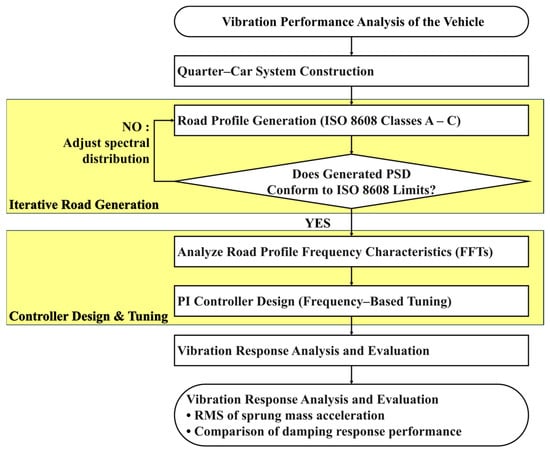
Figure 1.
Research flow chart.
2.1. MR-Damper and Quarter-Car Modeling
In this study, a quarter car and MR damper were modeled and simulated using AMESim 2404. An optimally designed configuration developed in a prior study was adopted for the additional-flow-path-type MR damper using ANSYS 2024 R3 [20]. The cross-sectional and flow-path views of the designed model, together with the damping-force model, are shown in Figure 2.
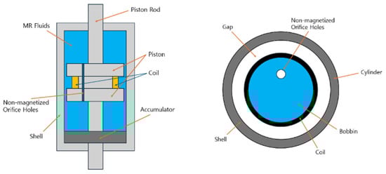
Figure 2.
Cross-sectional and flow-path views of the proposed MR damper [20].
The MR fluid selected for the design and analysis was LOAD Cooperation’s MRF-132 DG, known for its high-performance characteristics. The physical properties used in the mathematical and numerical models were based on the manufacturer’s data: a density (ρ) of 2950 kg/m3, a viscosity (μ) of 0.03 Pa·s, and a flow coefficient (C) of 2.5. The magnetic circuit was designed using ferromagnetic material AISI 1008 for the core and flux ring to ensure that the magnetic flux density (B) in the main flow gap (width Dgap = 1.1 mm, length Lgap = 26.1 mm) remains in the linear range of the B–H curve. The maximum yield stress (τy) generated in the fluid was calculated to reach 16.38 kPa at the maximum applied current of 1.0 A. This provides the necessary field-dependent parameters to accurately calculate the damping force component FMR.
Although Equations (1)–(6) follow the modeling framework of [20], Equation (6) notably originates from an experimentally obtained polynomial fit to the MRF-132DG fluid used in the additional-flow-path-type MR damper. The original study provides a field–stress relationship calibrated from measured data, and this constitutive curve was adopted in the present model without modification.
In Equation (1), the total damping force Fdamper is expressed as the superposition of three physically distinct contributions that describe the dominant flow mechanisms inside the MR damper. The laminar component Flaminar represents the viscous shear resistance generated by the MR fluid during fully developed flow in the main channel. The minor loss component Fminor accounts for the pressure drops associated with geometric discontinuities such as contractions, expansions, and valve edge separations, where localized turbulence and flow separation occur. The field dependent term FMR reflects the controllable yield stress force induced when the MR fluid is exposed to a magnetic field, which adds a tunable resistance independent of the viscous and minor loss effects. This decomposition is widely adopted because each mechanism contributes additively to the overall pressure drop along the flow path, allowing the total damping force to be represented as the sum of viscous, geometric-loss, and field-induced components.
In Equation (2), (Apiston − Arod) is the effective flow area produced by piston motion. The orifice pressure drop ΔPorifice consists of frictional and local losses. Here, Lorifice/Dorifice is the orifice aspect ratio (length to diameter), ρVorifice2/2 is the dynamic pressure, forifice is the laminar friction factor, and ζ denotes the local loss coefficient. This term represents the viscous damping caused by the laminar flow in the orifice passage.
Equation (3) isolates the contribution of local losses that occur at sharp geometric changes such as the orifice inlet and outlet. Unlike continuous viscous losses, this corresponds to pressure drops caused by area changes or abrupt section transitions.
In Equation (4), ΔPMR is the pressure differential induced by the yield stress of the MR fluid under an applied magnetic field, which is the actively controllable part of the damper via the coil current.
In Equation (5), Lgap is the flow-passage length, Dgap is the gap, C is the MR-fluid flow coefficient, and τy is the MR-fluid yield stress. This Bingham-type relationship indicates that the yield stress directly generates a pressure drop.
In Equation (6), B is the magnetic flux density in the magnetic circuit. This polynomial, obtained by experimental fitting, indicates a nonlinear increase in yield stress with field strength, which is approximately linear at low fields, with saturation-induced roll-off at higher fields.
Using the magnetic-field intensity and fluid-response characteristics obtained from ANSYS, an equivalent MR-damper model was constructed in AMESim, and vibration analyses were performed to reflect the fluid dynamics and damping characteristics. The key AMESim submodels used in the quarter-car model are summarized in Table 1, based on which a two degrees-of-freedom (2-DOF) quarter-car model was built. To maintain consistency and comparability with the previous structural design [20], the quarter-car parameters (Table 2) used herein are identical to those utilized in that prior work. The overall system configuration is shown in Figure 3, and the major parameter values for each component are listed in Table 2. The model comprised sprung mass (ms), unsprung mass (mu), suspension stiffness (ks), tire stiffness (kt), and an MR damper as the damping element. Equations (7) and (8) are the equations of motion of ms and mu, respectively.

Table 1.
Summary of the AMESim submodel usage and description.
Table 2.
Specifications of the quarter car.
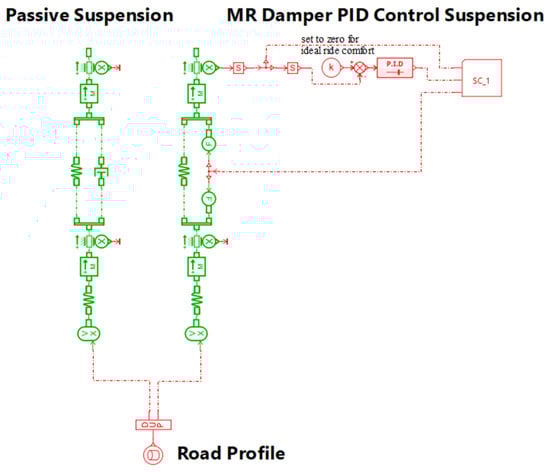
Figure 3.
AMESim quarter-car model with passive (left) and MR (right) dampers.
All simulations were performed using the standard integrator in AMESim with the solver mode set to Regular and the error type set to Mixed. The integration tolerance was 10−7, and the maximum allowable step size was 1030 s, enabling fully adaptive step-size control. Although a nominal maximum step size of 1030 s (the AMESim default), the effective time step is governed by the mixed-error tolerance of 10−7. The simulation was executed in dynamic mode over a 45 s horizon with a sampling frequency of 100 Hz (4501 points). These settings were used consistently for all passive- and MR-damper simulations.
2.2. ISO 8608 Road-Profile Modeling
2.2.1. Road-Profile Generation
Prior studies modeled road profiles using a time-domain continuous differential equation, as shown in Equation (9) [16]:
Here, zR(t) is the longitudinal road-displacement signal; α is the road-roughness coefficient that depends on road class; V is vehicle speed; and ω(t) denotes white-noise input. This model is used to represent the stochastic nature of road irregularities. Equation (9) assumes a linear mapping between distance and time via speed V and was designed to reflect the statistical characteristics of roads based on ISO 8608.
In contrast, the present study uses a distance-domain discrete difference, as in Equation (10), with distance as the independent variable, which offers a simpler numerical implementation and allows profile generation independent of vehicle speed, thereby facilitating its application across diverse driving conditions:
Here, zi is the longitudinal road displacement at position index i, and ωi denotes the white noise at position i. In this equation, zi and dx are in meters. To maintain unit consistency zi remains in [m]; α must have the unit of [m−1]; and ωi must have the unit of [m/]. This ensures that all terms on the right-hand side are dimensionally consistent with displacement, zi. To ensure the high numerical accuracy and spectral consistency required for vehicle dynamics simulations, the spatial discretization step was set to 0.05 m. This fine resolution effectively minimizes the numerical discretization errors inherent to converting a continuous model into discrete form. The filter coefficient α used in the discrete Equation (10) was calibrated to accurately match the required PSD slope of −2 on a log–log scale, to ensure that the synthesized profile adheres to the fractal-like characteristics of road roughness defined by ISO 8608 [22,23].
Both approaches aim to synthesize PSD-consistent road roughness but differ in the variable domain (time vs. distance), mathematical form (differential vs. difference), and treatment of the noise term (continuous vs. discrete with scaling).
In this study, we generated road profiles by filtering white noise based on first-order high-pass characteristics. The noise variance σ2 was adjusted by road class: 0.5, 2, and 8 for Classes A, B, and C, respectively. Profiles were generated sequentially using the above formulation, and three road profiles were generated by adjusting the variance and random seeds. Figure 4 shows the resulting profiles versus distance for each class.
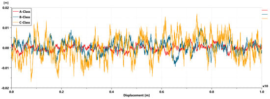
Figure 4.
A−, B−, and C−Class road profiles.
2.2.2. Power Spectral Density (PSD) Analysis
Quantifying the frequency characteristics of road roughness requires expressing the longitudinal profile using its PSD. Among the various estimators, Welch’s method is widely used, in which the signal is divided into overlapping segments; each segment is windowed; and the modified periodograms are averaged to improve estimation stability [24].
In this study, the segment length was set to 1024 samples, and the PSDs were estimated using Python 3.12.3’s scipy.signal.welch with scaling = ‘density’ to ensure unit consistency. The accuracy and statistical consistency of the spectral estimation were confirmed by verifying the methodology against standard, statistically known synthetic data, following established best practices for signal processing tools, such as Welch’s method. The objective of this work was to evaluate the MR-damper performance under idealized ISO 8608 road conditions, which are defined by theoretical spectral boundaries, not empirical road measurements [25]. Therefore, the primary validation criterion was the compliance of the generated profile’s PSD with the theoretical ISO 8608 limits, rather than comparisons with real-world road data. The resulting PSDs were then used to assess ISO 8608 road-class compliance.
2.2.3. Comparison with the ISO 8608 B-Class Criterion
The ISO 8608 classifies road roughness based on PSD. For Classes A–C, the PSD model is given by Equation (11) [3]:
For each class, the upper and lower bounds are defined around Gd(Ω0) at the reference angular spatial frequency Ω0, and class conformity is determined by whether the PSD of the generated profile is within these bounds. The upper and lower limits were 2.0 × Gd(Ω0) and 0.5 × Gd(Ω0), respectively. The compliance of the simulated profiles with these limits was verified, and the results are shown in Figure 5. For Class A, no lower bound was specified; thus, only the upper limit was applied.
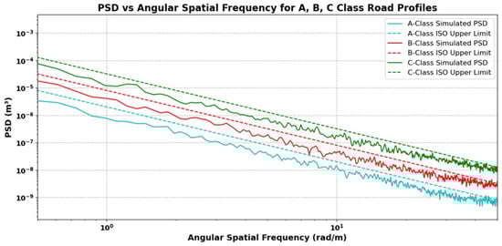
Figure 5.
PSD vs. angular spatial frequency for A-, B-, and C-Class road profiles.
Because gradually attenuated low-frequency content (high-pass behavior) was used by this filter, the PSD slightly exceeds the upper limit in the high angular spatial-frequency range.
2.3. Controller Design for the MR Damper
2.3.1. PI Controller
For the MR damper control, we employed feedback control of the proportional–integral–derivative (PID) type. A PID controller combines proportional (P), integral (I), and derivative (D) actions to drive the plant output toward the reference. Given its industrial maturity, modest computational burden, and low implementation cost, PID control provides a robust performance under standardized road excitations. The fundamental objective of this semi-active suspension system is to maximize ride comfort by minimizing the acceleration transmitted to the sprung mass. The control action is based on the error, which is defined as the difference between the desired sprung mass acceleration (reference, set to zero for ideal ride comfort) and measured sprung mass acceleration: e(t) = 0 − . The control law is given by Equation (12):
where e(t) is the tracking error and u(t) denotes the ideal control force that drives the sprung-mass acceleration to zero. Figure 6a compares the simulated force–velocity curve at the 0.1 Hz tuning condition with the reference reported in [20], showing that the model adheres closely to the validated piecewise–linear characteristics. Figure 6b provides a quantitative assessment by presenting the distribution of the exceeding force, defined as the positive deviation of the simulated output from the reference. Although 49.023% of the samples exceed the reference, the magnitude of the exceedance remains small: the maximum deviation is 2.731 N, which corresponds to approximately 10% of the local reference force level (Flimit = 25.569 N) at the relevant velocity. Because these exceedances occur only at isolated extreme points and remain well below the characteristic force scale of the MR damper, their influence on overall dynamic performance is negligible. This confirms that the implemented model accurately reproduces the validated behavior reported in [20]. Although approximately half of the samples lie marginally above the reference due to the discrete implementation of the piecewise–linear envelope, the deviations are uniformly small and confined to low-sensitivity regions of the curve.
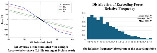
Figure 6.
(a) Overlay of the simulated MR-damper force–velocity curve (0.1 Hz tuning) with the results from [20]. (b) Relative-frequency histogram of the exceeding force, defined as the positive deviation from the reference.
If the MR damper produces an excessively large damping force, unnecessary energy consumption and coil damage may occur because of the overcurrent. Conversely, appropriate force limiting can mitigate the damper’s nonlinear hysteresis. Based on the designed MR-damper model and performance analyses, the allowable force was bounded, as shown in Equations (13)–(17).
where Fpid denotes the force commanded by the controller prior to saturation and FMR is the realized MR-damper force after applying the bounds.
2.3.2. PID Gain Tuning
Figure 7 reports the frequency characteristics of the road profiles, with dominant road-excitation components at 0.022, 0.10, 0.35, 0.55, and 0.71 Hz as identified by FFT analysis. Figure 8a confirms that the reduced first-order process (FOP) model accurately captures the dominant dynamics of the linearized plant, as demonstrated by agreement in both the Bode magnitude/phase and step-response characteristics. Figure 8b presents the corresponding closed-loop PI gains obtained from the AMESim PID Tuner for the 0.022-Hz tuning condition. To explicitly document the stability margins used for controller validation, Figure 8c provides the full Bode magnitude and phase diagrams of the loop-transfer function , from which the gain margin (≈62.1 dB) and phase margin (≈51.3°) are obtained at a gain-crossover frequency of approximately 240 Hz. These results serve as the primary stability references for the subsequent tuning analysis.
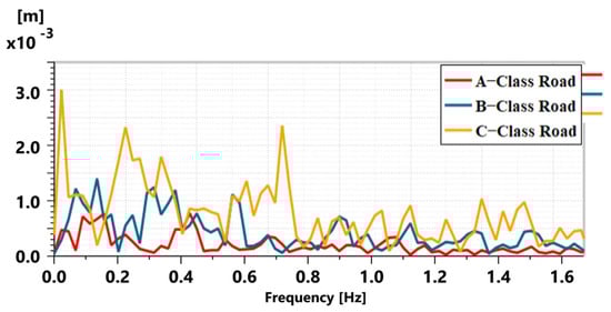
Figure 7.
Road profile (FFT) of Classes A, B, and C.
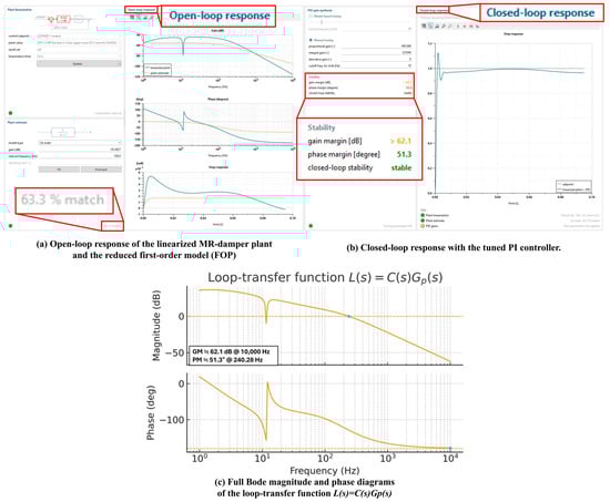
Figure 8.
PI-controller tuning and loop-transfer stability analysis. (a) Open-loop Bode magnitude and phase responses of the linearized MR-damper plant, compared with the reduced first-order model (FOP). (b) Closed-loop step response of the PI-controlled system. (c) Full Bode magnitude and phase diagrams of the loop-transfer function L(s) = C(s)Gp(s), showing a gain margin of at least 62.1 dB at approximately 10 kHz and a phase margin of approximately 51.3° at a gain–crossover frequency of about 240 Hz.
The MR damper retains strong nonlinear force–velocity behavior even with the additional flow path; therefore, all controller parameters were tuned strictly under closed-loop conditions. The AMESim model was linearized at and . Because the open-loop response of exhibits no 0-dB crossover, classical gain and phase margins cannot be extracted from the plant alone, and stability must instead be evaluated from the loop-transfer function . The stability margins shown in Figure 8c are fully consistent with those obtained directly from the AMESim PID Tuner.
For analytical tuning, the linearized plant was reduced to a first-order process , as no dead time was present in the identified dynamics. The static gain was obtained by least-squares fitting of the low-frequency magnitude response of the linearized plant, yielding . The time constant was computed using the 63.2% rise-time rule, giving [26], and the delay term was set to zero. Applying the internal-model-control (IMC) relations with a design constant produced initial PI gains of and .
These IMC-derived gains were then refined using the AMESim closed-loop PID tuner. The refinement followed two explicit quantitative criteria: (i) achieving a phase margin of approximately 50° in the loop-transfer function, and (ii) minimizing the RMS upper-mass acceleration over the dominant ISO 8608 excitation band (0.022–0.71 Hz). Because the magnitude of the linearized plant lies far below 0 dB, the IMC-derived gains did not yield adequate loop gain to satisfy either criterion, necessitating an increase in both and .
This systematic closed-loop refinement consistently produced final gains in the range and , as reported in Table 3. At the 0.022-Hz tuning condition, the AMESim step-response and frequency-response outputs confirm a phase margin of 51.3° and a gain margin of 62.1 dB, together with fast settling and minimal overshoot. The same procedure applied across the other excitation frequencies likewise yielded loop gains exceeding 60 dB. Collectively, the FOP reduction, IMC synthesis, and AMESim-based closed-loop refinement form a consistent and analytically supported tuning framework for MR-damper control.
Table 3.
PID gain tuning results for 0.022, 0.1, 0.35, 0.55, and 0.71 Hz.
3. Results
This section provides a concise and precise description of the experimental results, their interpretation, as well as the conclusions drawn from them in the following subsections.
3.1. PI Gain Tuning and Response
To minimize the acceleration of the sprung mass, we applied a frequency-response-based controller design and closed-loop performance optimization to compute the PI gains at each target frequency (0.022, 0.1, 0.35, 0.55, and 0.71 Hz). The derivative term (Kd) was omitted because of potential stability degradation, and the proportional (Kp) and integral (Ki) terms were adjusted to achieve favorable settling time, overshoot, and steady-state error. The final tuned gains are listed in Table 3.
The core focus of this study is not to verify the repeatability of a single scenario, but to demonstrate the adaptive performance of the control system based on the frequency characteristics defined across the A, B, and C classes of the ISO 8608 standard. To quantitatively evaluate this performance, ms responses were first reconstructed by interpolating between the discrete time samples obtained over a total duration of 45 s with a fixed sampling interval of 10−2 s, using the piecewise cubic Hermite interpolating polynomial (PCHIP). The RMS values of these interpolated acceleration signals were then computed to assess the vibration characteristics of the MR-damper control system. As the controller was tuned based on the governing frequencies extracted by FFT analysis, the main objective was to demonstrate robust performance of the statistical characteristics inherent to these wide-ranging road environments. The corresponding performance improvements are summarized in Table 4, Table 5 and Table 6.
Table 4.
Comparison of the upper mass acceleration RMS and improvement rate for the MR damper tuned at various frequencies under Class-A road excitation.
Table 5.
Comparison of the upper mass acceleration RMS and improvement rate for the MR damper tuned at various frequencies under Class-B road excitation.
Table 6.
Comparison of the upper mass acceleration RMS and improvement rate for the MR damper tuned at various frequencies under Class-C road excitation.
3.2. Comparison Between the Additional-Flow-Path-Type MR and Passive Dampers
The primary metric for evaluating the vibration suppression capability of the proposed system against the conventional PS system is the RMS of the sprung-mass acceleration. The use of RMS acceleration inherently averages the performance over the entire 45 s duration, providing a reliable measure of sustained ride comfort, thereby circumventing the ambiguity associated with instantaneous peak performance analysis.
Under identical road excitations (A-, B-, and C-class), the additional-flow-path-type MR damper system, controlled by the frequency-tuned PI controller, consistently maintained a significantly lower RMS acceleration than to the PS system. Across all tested conditions and tuning frequencies, the MR damper demonstrated a minimum improvement of approximately 26.626% (B-Class, 0.1 Hz tuning) and a maximum improvement of 29.712% (C-Class, 0.55 Hz tuning).
This sustained performance differential validates the effectiveness of the semi-active control strategy, which actively regulates the damping force in real-time according to the frequency content of the road input. Focusing on overall RMS reduction, the results confirm the inherent advantage of the MR damper’s variable rheological properties in providing superior energy dissipation management throughout diverse driving conditions, irrespective of the instantaneous phase relationship between the two systems’ acceleration responses.
3.3. Comparison Across Controller-Tuning Frequencies
The analysis of RMS acceleration reduction across five distinct tuning frequencies (0.022, 0.1, 0.35, 0.55, and 0.71 Hz) revealed a key finding: the performance improvement exhibited remarkable stability, showing a consistent acceleration reduction magnitude regardless of the tuning frequency or the road class. Specifically, the low-frequency group (0.022 and 0.1 Hz) provided an average RMS reduction in the range of 26.626 to 27.698%, which is comparable to that of the high-frequency group (0.35, 0.55, and 0.71 Hz) clustered around the 28.741 to 29.712% range. Furthermore, the magnitude of improvement remained largely consistent across all road classes. This high consistency is primarily attributed to the structural linearity of the MR damper. The additional-flow-path design, which alleviates the conventional block-up issue and results in a more linear and stable force response. This structural advantage minimizes the performance degradation typically seen when a controller tuned for one specific frequency is applied to disturbances with different spectral content, confirming the robust stability of the system.
3.4. Passive Versus MR Damper
The MR damper adjusts its damping force in real time via the control current, enabling exploitation of nonlinear damping beyond the linear range. Figure 9 presents the force–velocity characteristics of the MR damper under two controller tuning frequencies—0.1 Hz for the B-class road profile and 0.55 Hz for the C-class road profile. Subplots (a) and (c) show that the controller effectively operates within the nonlinear force envelope across the relevant frequency range; subplots (b) and (d) compare the MR damper force with the force generated by the PID-based reference controller, illustrating how the controller output remains bounded by the physical constraints of the MR actuator. Figure 9e shows the distribution of FMR and FPID for the representative B-class road at the 0.1-Hz tuning condition. Points lying on the identity line correspond to the narrow unsaturated range (–1.862 to 1.692 N), while the remaining points indicate saturated intervals, confirming that the controller output is consistently projected onto the physically admissible force boundary without introducing discontinuities in closed-loop operation. Figure 9f shows that the time-domain outlines of FMR and FPID are closely aligned, indicating that saturation does not materially affect the controller’s behavior. Across the full 45 s simulation, 93.4% of the samples fall within the saturated region, yet Figure 9e,f confirms that the projection of FPID onto the admissible boundary does not introduce any measurable distortion or discontinuity in the closed-loop force response.
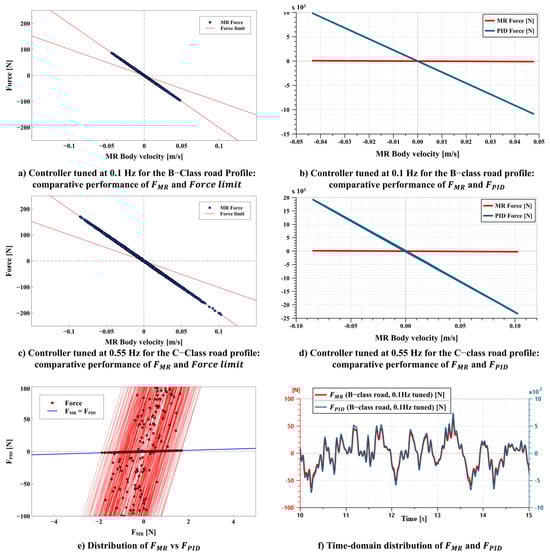
Figure 9.
Force–velocity characteristics of the MR damper under two tuning conditions: Controller tuned at (a) 0.1 Hz for B-class road profile— and force-limit boundary compared; (b) 0.1 Hz for B-class road profile— and compared; (c) 0.55 Hz for C-class road profile— and force-limit boundary compared; and (d) 0.55 Hz for C-class road profile— and compared. (e) Distribution of FMR vs. FPID, showing a narrow unsaturated matching range (–1.862 to 1.692 N) and saturated points projected onto the admissible force boundary, (f) Time-domain distributions of FMR and FPID; they have similar time domain distributions and outlines.
Notably, the ideal control force lies far outside the physically attainable force range of the MR actuator, because it is derived under the idealized constraint , a condition that cannot be satisfied under broadband ISO 8608 road excitations at realistic driving speeds. Consequently, the commanded force repeatedly exceeds the nonlinear force capacity of the actuator across all combinations of road classes (A–C) and tuning frequencies (0.022–0.71 Hz), resulting in persistent activation of the force-limiting mechanism. In quantitative evaluations over the 45-s simulation interval, the MR damper remains saturated for approximately 93–94% of the duration in all 15 cases. Specifically, at saturation ratios for the A-class input range of 93.64–93.67%, those for the B-class input remain nearly constant at 93.87%, whereas those for the C-class input fall within 93.76–93.80%. These brief non-saturated intervals occur only in low-velocity regions where the ideal force demand momentarily enters the feasible force envelope. However, the exact saturation percentage was not a performance metric of interest in this study. The purpose of the analysis was to demonstrate that force limiting is consistently invoked under realistic broadband excitations, not to minimize the saturation ratio. Therefore, in all cases, the realized force presented in Figure 9 represents the clipped and physically admissible counterpart of the idealized demand. A detailed summary of the saturation ratios for all class–tuning combinations is provided in Table 7, confirming the narrow 93–94% saturation band across all 15 cases.
Table 7.
Saturation ratio of the MR Damper across ISO 8608 road classes and PI tuning frequencies.
In addition, because the MR-damper model incorporates ANSYS 2024 R3-derived magnetic-field and fluid-response characteristics under the maximum current condition, the simulated force capacity inherently satisfies the physical upper envelope of theforce–velocity responses reported in [20].
To assess how force saturation influences damping energy, the quantity was evaluated in a 45-s simulation under the 0.55-Hz tuning frequency on the ISO C-class road. The ideal unconstrained control demand theoretically dissipates 20,232.56 J, whereas the force-limited MR damper dissipated only 245.69 J, corresponding to a 98.8% reduction induced by the continuous clipping. The passive damper dissipated 1088.46 J, confirming that semi-active control inherently expends far less mechanical energy than a conventional passive system. Despite this substantial reduction in dissipated energy, ride-comfort performance improved significantly: the sprung-mass acceleration RMS decreased from 0.7642 m/s2 (passive) to 0.5372 m/s2 (realized MR) and reached 0.2217 m/s2 under ideal PID demand. These results demonstrate that saturation limits excessive or non-physical force demands while preserving the dominant control action required for vibration attenuation, highlighting the characteristic efficiency of semi-active MR suspension systems.
Table 8 presents the vehicle-class-dependent RMS damping force under passive and MR suspension conditions. As the road roughness increases, the RMS damping force in the PS condition increases from approximately 51 N for A-class to 213 N for C-class roads. When MR suspension is applied, the damping force for all classes decreases to about 26% of the PS level, corresponding to a reduction of approximately 73–74%. This indicates that the proposed MR + PI control strategy maintains a relatively consistent damping reduction ratio regardless of road roughness classification. Furthermore, even though the PI controller gains were tuned based on the characteristic frequencies extracted from the FFT of the road profile, the variation in RMS damping force within the same road class remained within 0.4%, suggesting that the average damping force acting on the sprung mass is governed primarily by the application of the MR damper rather than the specific frequency used for controller tuning. Figure 10 shows the comparison of the body response and damper force between the passive and MR dampers under C-class road excitation, including (a) body displacement, (b) sprung-mass acceleration, and (c) damper force.
Table 8.
Vehicle-class-dependent RMS damping force under passive and MR suspension conditions.
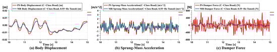
Figure 10.
Comparison of body response and damper force between passive and MR dampers under C-class road excitation: (a) body displacement, (b) sprung-mass acceleration, and (c) damper force.
4. Discussion
4.1. Engineering Implications for Precision Control and Dynamic Stability
The additional-flow-path-type MR damper employed in this study mitigates the block-up phenomenon inherent to conventional piston–orifice configurations, thereby maintaining a damping force–velocity response that is closer to linear. This structural linearity plays a critical role in securing a phase margin of approximately 51° in the closed-loop system. These findings are consistent with prior studies reporting that improvements in the internal flow architecture of MR dampers markedly enhance the stability of MR-damper-based vibration control systems [7,8].
Furthermore, the frequency-domain PI control adopted in this study adjusts its gain to match the dominant frequencies of the ISO 8608 road spectrum, enabling precise modulation of damping force with respect to the sprung-mass acceleration, which directly affects ride comfort. Experimental results show that the RMS acceleration was reduced by 22–29% across road classes A–C, with performance variations remaining within ±1% even when the tuning frequency was varied between 0.022 and 0.71 Hz. This demonstrates not only the effectiveness of frequency matching in the controller but also the robustness of the enhanced structural linearity in preserving dynamic stability over a broad range of input spectra. Such consistent stability aligns with theoretical discussions emphasizing that mitigating structural nonlinearities in dampers is essential for ensuring the effectiveness of semi-active suspension control strategies across the wide bandwidth characteristic of road PSDs [11].
The closed-loop frequency response was computed numerically by applying a single-sided FFT amplitude spectrum to the sprung-mass acceleration signal. The FFT was evaluated over the full 45 s record using a rectangular window (no tapering), no overlap, and single-sided amplitude normalization based on the standard 2/N scaling; a five-point moving-average filter was applied to reduce high-frequency fluctuations in the spectral estimate. This approach is widely used in semi-active suspension research, as it directly reveals how the closed-loop system responds to road-induced disturbances across frequencies. For the B-class input (0.10 Hz tuning), the passive suspension exhibited a dominant resonance at 1.51 Hz, with a peak amplitude of 4.36 × 10⁻² m/s2. With the PI-controlled MR damper, the resonance amplitude at the same frequency decreased to 2.38 × 10⁻² m/s2, corresponding to a reduction of . This dB value is computed from the ratio of the linear spectral amplitudes and is not taken directly from the plotted axis, since Figure 11 presents the amplitude spectrum in linear units of m/s2. A similar trend was observed under the C-class input (0.55 Hz tuning), where both systems exhibited a dominant resonance at 1.44 Hz with the PI-controlled system again reducing the peak by approximately 5.2 dB. These results demonstrate that the PI controller does not shift the resonance frequency rather, it suppresses the amplification in the resonance band by about 5.2 dB, effectively increasing the closed-loop damping and altering the dynamic characteristics in a stabilizing manner. The consistency of this attenuation across multiple road excitations confirms that the frequency-domain tuning modifies the closed-loop gain profile around the dominant excitation band of the ISO 8608 spectrum, thereby enhancing the robustness of the closed-loop response. Figure 11 illustrates the closed-loop frequency-response magnitudes (amplitude spectra) of the sprung-mass acceleration under B and C-class road excitations. In both cases, the PI-controlled MR suspension reduces the resonance amplitude by approximately 5.2 dB without shifting the resonance frequency. This demonstrates that the PI controller enhances the effective damping of the closed-loop system, thereby suppressing resonance amplification and stabilizing the overall dynamic behavior.
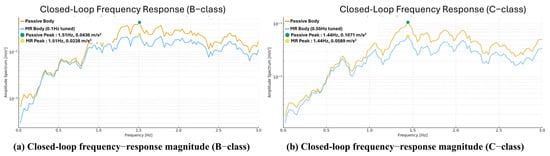
Figure 11.
Closed-loop frequency-response magnitude of the sprung-mass acceleration under two road excitations. (a) B-class road with a 0.10 Hz PI tuning. (b) C-class road with a 0.55 Hz PI tuning.
4.2. Energy Dissipation Management and System Reliability
The MR damper system presented in this study exhibited excellent energy-dissipation management ability compared with that of the passive damper. The passive damper generates a fixed resistance and continuously dissipates unnecessary energy into heat, whereas the semi-active MR damper selectively generates only the necessary amount of damping force according to the dynamic characteristics of the vehicle. As a result, the average force transmitted to the system (RMS damping force) decreased by approximately 73–74% relative to the passive configuration, indicating a substantial reduction in unnecessary energy dissipation.
Minimizing energy dissipation provides the following systematic benefits:
- Operational efficiency improvement: reducing the heat generation of the system and dynamic load improves the overall operational efficiency and performance of the vehicle.
- Increased component durability: reducing the average load on suspension system components, such as bushings and mountings, extends the fatigue life, especially by significantly reducing the fatigue damage to structures through adaptive control. This demonstrates that the system considered in this study contributes to long-term sustainability [27].
Additionally, the MR damper design with an additional flow path structure suggests structural improvement measures for increasing the operational reliability of the system by ensuring the flow stability of the MR fluid and alleviating the nonlinearity of the control response.
4.3. Limitations and Differentiation from Existing Research
The present study addresses the limitation that recent work on energy consumption and regeneration in semi-active suspensions largely relies on optimization-based or time-domain controllers that do not embed the spectral characteristics of road excitations [28,29]. Likewise, nonlinear vibration-control methods developed for primary-resonance suppression target analytical resonance behavior rather than broadband stochastic inputs [30]. In contrast, this study integrates road-input frequency content directly into the PI control architecture by extracting dominant frequencies from the ISO 8608 PSD via FFT and tuning the gains accordingly. Simulations show that the RMS sprung-mass acceleration is reduced while the RMS damping-force demand remains at approximately 26% that of the passive system, demonstrating concurrent improvement in ride comfort and mechanical-energy-dissipation efficiency.
Combined with an auxiliary-flow-path MR damper that mitigates nonlinear flow effects, the proposed method further suppresses damping-force saturation, improves thermal stability, and reduces component fatigue loading. Nonetheless, the findings are based on a quarter-car, 2-DOF model and therefore do not account for pitch–roll coupling in full-vehicle dynamics. The electrical power consumption of the MR damper coil also remains unquantified, as the study focuses on mechanical energy dissipation and dynamic stability. In addition, the RMS responses reported in this study are based on a single ISO 8608 realization per road class at 80 km/h. As ISO 8608 profiles are intrinsically stochastic, multi-realization Monte-Carlo analysis is required to quantify the statistical variability in RMS acceleration and damping-force demand. This extended robustness assessment falls beyond the scope of the present work but will be addressed in future studies along with current-dependent MR-damper control. Overall, the contribution lies not in controller complexity but in embedding frequency characteristics into a simple control structure and demonstrating that its integration with a flow-linearized MR-damper yields consistent gains in energy dissipation, dynamic robustness, and saturation suppression. Future work should extend this framework to full-vehicle models and incorporate power-electronics analysis.
5. Conclusions
This study quantitatively validates the enhanced ride quality and stable control potential of a passenger vehicle by integrating an additional-flow-path-type MR damper with a frequency-based PI control strategy. The key conclusions and engineering implications derived from the 2-DOF quarter-car model simulation, implemented using AMESim under ISO 8608 standard road profiles (Classes A, B, and C), are as follows:
- The RMS sprung-mass acceleration was reduced by 22–29% compared with the passive suspension across all road classes. This demonstrates empirically that the proposed frequency-based PI control strategy effectively modulates the damping force within the dominant frequency range, thereby suppressing low-frequency vibrations that govern ride comfort. Moreover, varying the tuning frequency from 0.022 to 0.71 Hz resulted in less than ±1% performance deviation, indicating that the controller performance is not sensitive to the specific tuning-frequency setting.
- The RMS damping force of the MR damper remained at approximately 26% that of the passive configuration, indicating a substantial reduction in the required damping-force level under identical excitation conditions. This confirms that the controller, together with the auxiliary-flow-path design, effectively suppresses unnecessary force saturation and stabilizes the mechanical response of the system. Electrical power consumption and current-dependent effects were not included in the present analysis and therefore no energy-related interpretations are drawn here. These aspects will be addressed in future work through dedicated current profiling and power-consumption modeling.
- Regarding the limitations due to model simplification and directions for future research, because this study employed a 2-DOF quarter-car model, it does not account for pitch, roll, and coupled vehicle dynamics present in real vehicles. Accordingly, the performance improvements demonstrated here should be interpreted as a validation of general trends and require further examination to determine whether similar improvements can be achieved in full-car configurations. Furthermore, because the ISO 8608 road profiles used in this study were based on a single realization per class, future work should also incorporate multi-realization stochastic analyses to evaluate the statistical robustness of the proposed control strategy, as follows.
- -
- Measurement of damping-force–current characteristics using a hydraulic test system;
- -
- Validation of control responses through hardware-in-the-loop simulation (HILS)-based quarter-car experimentation;
- -
- Evaluation of scalability via full-car tests under actual driving conditions.
These staged experimental verifications will enable the performance assessment of the proposed frequency-based control strategy, demonstrating that the structural advantages of the additional-flow-path-type MR damper can be consistently reproduced under realistic vehicle operating conditions.
Author Contributions
Conceptualization, methodology, software, validation, formal analysis, investigation, resources, data curation, and writing—original draft preparation S.W. and C.J.; Conceptualization and methodology, S.K.; Conceptualization, methodology, writing—review and editing, visualization, supervision, project administration and funding acquisition, J.L. All authors have read and agreed to the published version of the manuscript.
Funding
This study was funded by the Korea Institute of Energy Technology Evaluation and Planning (KETEP) and Ministry of Trade, Industry, and Energy (MOTIE) of the Republic of Korea (No. RS-2024-00398166).
Data Availability Statement
The road profile data, PI gain sets, and MR-damper performance results used in this study are provided within the article. Additional simulation data generated during the modeling process are available from the corresponding author upon reasonable request.
Conflicts of Interest
The authors declare no conflicts of interest.
References
- Carlson, J.D.; Jolly, M.R. MR fluid, foam and elastomer devices. Mechatronics 2000, 10, 555–569. [Google Scholar] [CrossRef]
- Savaresi, S.M.; Poussot-Vassal, C.; Spelta, C.; Sename, O.; Dugard, L. Semi-Active Suspension Control Design for Vehicles; Elsevier: Amsterdam, The Netherlands, 2010. [Google Scholar]
- ISO 8608; Mechanical Vibration—Road Surface Profiles—Reporting of Measured Data. International Organization for Standardization: Geneva, Switzerland, 2016.
- Žáček, J.; Strecker, Z.; Jeniš, F.; Macháček, O.; Goldasz, J.; Sapinski, B.; Vrbka, M.; Kubík, M. Impact of magnetorheological fluid composition on their behaviour in gradient pinch mode. Sci. Rep. 2024, 14, 31320. [Google Scholar] [CrossRef] [PubMed]
- Rouabah, S.; Didouche, F.-Y.; Khebli, A.; Aguib, S.; Chikh, N. The Advancing Understanding of Magnetorheological Fluids and Elastomers: A Comparative Review Analyzing Mechanical and Viscoelastic Properties. Magnetochemistry 2025, 11, 62. [Google Scholar] [CrossRef]
- Kumar, J.S.; Paul, P.S.; Raghunathan, G.; Alex, D.G. A review of challenges and solutions in the preparation and use of magnetorheological fluids. Int. J. Mech. Mater. Eng. 2019, 14, 13. [Google Scholar] [CrossRef]
- Weber, F. Semi-active vibration absorber based on real-time controlled MR damper. Mech. Syst. Signal Process. 2014, 46, 272–288. [Google Scholar] [CrossRef]
- Wang, J.; Zhang, X.; Liu, Y.; Qin, Z.; Ma, L.; Hong, F.; Chu, F. Dynamic analysis of magnetorheological damper incorporating elastic ring in coupled multi-physical fields. Mech. Syst. Signal Process. 2024, 208, 111040. [Google Scholar] [CrossRef]
- Yao, G.Z.; Yap, F.F.; Chen, G.; Li, W.H.; Yeo, S.H. MR damper and its application for semi-active control of vehicle suspension system. Mechatronics 2002, 12, 963–973. [Google Scholar] [CrossRef]
- Du, H.; Yim Sze, K.; Lam, J. Semi-active H∞ control of vehicle suspension with magneto-rheological dampers. J. Sound Vib. 2005, 283, 981–996. [Google Scholar] [CrossRef]
- Alleyne, A.; Hedrick, J.K. Nonlinear adaptive control of active suspensions. IEEE Trans. Control Syst. Technol. 1995, 3, 94–101. [Google Scholar] [CrossRef]
- Viadero-Monasterio, F.; Meléndez-Useros, M.; Jiménez-Salas, M.; Boada, B.L. Robust Static Output Feedback Control of a Semi-Active Vehicle Suspension Based on Magnetorheological Dampers. Appl. Sci. 2024, 14, 10336. [Google Scholar] [CrossRef]
- Viadero-Monasterio, F.; Meléndez-Useros, M.; Jiménez-Salas, M.; López Boada, M.J. Avoiding Lyapunov-Krasovskii Functionals: Simple Nonlinear Sampled–Data Control of a Semi-Active Suspension with Magnetorheological Dampers. Machines 2025, 13, 512. [Google Scholar] [CrossRef]
- Loprencipe, G.; Zoccali, P. Use of generated artificial road profiles in road roughness evaluation. J. Mod. Transp. 2017, 25, 24–33. [Google Scholar] [CrossRef]
- Dharankar, C.S.; Hada, M.K.; Chandel, S. Numerical generation of road profile through spectral description for simulation of vehicle suspension. J. Braz. Soc. Mech. Sci. Eng. 2017, 39, 1957–1967. [Google Scholar] [CrossRef]
- Nanthakumar, A.J.D.; Jariwala, K.; Kumawat, H. Mathematical modeling and simulation of longitudinal road profiles. AIP Conf. Proc. 2020, 2277, 130002. [Google Scholar] [CrossRef]
- El-Kafafy, M.; El-Demerdash, S.M.; Rabeih, A.-A.M. Automotive ride comfort control using MR fluid damper. Engineering 2012, 4, 179–187. [Google Scholar] [CrossRef][Green Version]
- Oh, J.-S.; Choi, S.-B. Ride Quality Control of a Full Vehicle Suspension System Featuring Magnetorheological Dampers With Multiple Orifice Holes. Front. Mater. 2019, 6, 8. [Google Scholar] [CrossRef]
- Xu, F.; Xia, X.; Cao, J.; Liu, P.; Ning, D.; Du, H. Multi-model Switching Control Study of a Full-Car Suspension System for Balancing Ride Comfort and Handling Stability. Chin. J. Mech. Eng. 2025, 38, 166. [Google Scholar] [CrossRef]
- Kim, M.; Yoo, S.; Yoon, D.; Jin, C.; Won, S.; Lee, J. Numerical Analysis of the Vehicle Damping Performance of a Magnetorheological Damper with an Additional Flow Energy Path. Appl. Sci. 2024, 14, 10575. [Google Scholar] [CrossRef]
- Lenkutis, T.; Čerškus, A.; Šešok, N.; Dzedzickis, A.; Bučinskas, V. Road Surface Profile Synthesis: Assessment of Suitability for Simulation. Symmetry 2021, 13, 68. [Google Scholar] [CrossRef]
- Tyan, F.; Hong, Y.-F.; Tu, S.-H.; Jeng, W.S. Generation of Random Road Profiles. J. Adv. Eng. 2009, 4, 151–156. [Google Scholar] [CrossRef]
- Wang, W.; Hua, X. Modeling the Road Roughness for Automotive Dynamics Simulation. In Proceedings of the 2019 International Conference on Modeling, Analysis, Simulation Technologies and Applications (MASTA 2019), Hangzhou, China, 26–27 May 2019. [Google Scholar] [CrossRef]
- Astfalck, L.C.; Sykulski, A.M.; Cripps, E.J. Debiasing Welch’s method for spectral density estimation. Biometrika 2024, 111, 1313–1329. [Google Scholar] [CrossRef]
- Múčka, P. Simulated Road Profiles According to ISO 8608 in Vibration Analysis. J. Test. Eval. 2018, 46, 405–418. [Google Scholar] [CrossRef]
- Ogata, K.; Yang, Y. Modern Control Engineering; Prentice-Hall: Upper Saddle River, NJ, USA, 2010; Volume 5. [Google Scholar]
- Behboodi, S.; Bitaraf, M.; Nafisifard, M. Prevention of low-cycle fatigue damage using adaptive control approach and magnetorheological dampers. Structures 2021, 33, 554–566. [Google Scholar] [CrossRef]
- Azmi, R.; Mirzaei, M.; Habibzadeh-Sharif, A. A novel optimal control strategy for regenerative active suspension system to enhance energy harvesting. Energy Convers. Manag. 2023, 291, 117277. [Google Scholar] [CrossRef]
- Zhang, B.; Luo, M.; Tan, C.A. Ride comfort and energy harvesting of inflatable hydraulic-electric regenerative suspension system for heavy-duty vehicles. J. Mech. Sci. Technol. 2024, 38, 2277–2289. [Google Scholar] [CrossRef]
- Kandil, A.; Hamed, Y.S. Integral Resonant Controller for Suppressing Car’s Oscillations and Eliminating its Inherent Jump Phenomenon. Eur. J. Pure Appl. Math. 2023, 16, 2729–2750. [Google Scholar] [CrossRef]


Disclaimer/Publisher’s Note: The statements, opinions and data contained in all publications are solely those of the individual author(s) and contributor(s) and not of MDPI and/or the editor(s). MDPI and/or the editor(s) disclaim responsibility for any injury to people or property resulting from any ideas, methods, instructions or products referred to in the content. |
© 2025 by the authors. Licensee MDPI, Basel, Switzerland. This article is an open access article distributed under the terms and conditions of the Creative Commons Attribution (CC BY) license (https://creativecommons.org/licenses/by/4.0/).