Abstract
In spoke-type permanent magnet synchronous motors (PMSMs), an asymmetric rib structure has been investigated as a method to reduce cogging torque. However, such rotor asymmetry tends to an increase in the axial force, which limits its applicability in precision and low-vibration systems. To overcome this limitation, this study proposes a new motor design method that introduces a skew factor as an additional design variable. The skew factor, defined as the ratio of the skewed region to the total stack length, enables simultaneous control of cogging torque and axial force by adjusting the degree of asymmetry along the rotor stack. Using parametric modeling and finite element analysis (FEA), the combined effects of the asymmetric rib and skew factor were investigated, and an optimized motor structure achieving balanced cogging torque and axial force characteristics was derived. The proposed design approach provides an effective method for simultaneously considering cogging torque and axial force in spoke-type PMSMs.
1. Introduction
Electric motors are widely used as essential power sources in various fields, such as industrial equipment, household appliances, and electric vehicles (EVs), and the demand for high-efficiency and high-performance motors has been continuously increasing. The performance of such motors strongly depends on the characteristics of permanent magnets, and rare-earth magnets have been extensively utilized for high-performance motor applications due to their excellent magnetic properties [,,,]. However, the supply of rare-earth resources is concentrated in specific countries, which poses risks of price volatility and supply chain instability. More recently, the growing scarcity and supply instability of rare-earth resources have caused significant uncertainty in global industries. In addition, the environmental burdens associated with mining and refining processes have been identified as factors that hinder sustainable development. Consequently, research on rare-earth-free motors has been actively pursued to reduce reliance on rare-earth materials and to secure stable technological alternatives.
Representative examples of rare-earth-free motors include induction motors, ferrite permanent magnet motors, switched reluctance motors (SRMs), and synchronous reluctance motors (SynRMs). Induction motors are widely used due to their simple structure, high durability, and proven reliability. However, when compared with permanent magnet motors, they exhibit lower output density (i.e., less torque per unit mass or volume) and a narrower operating range, which limit their suitability as next-generation traction sources. SRMs and SynRMs do not require rare-earth magnets, but they also have lower output density than permanent magnet motors and suffer from vibration and noise issues during operation, making them less suitable for high-performance applications [,,,,,]. To overcome these limitations, ferrite-based spoke-type motors have emerged as promising candidates for achieving performance levels comparable to rare-earth permanent magnet motors [,,,,,].
The spoke-type motor contains ferrite magnets arranged radially inside the rotor to concentrate flux, thereby compensating for the relatively low magnetic performance of ferrite and enabling a higher air-gap flux density. However, because the spoke structure mainly relies on permanent magnet torque, there is a limitation in further improving torque density. To address this issue, the double-spoke structure has been proposed []. The double-spoke motor maintains the advantages of the conventional spoke structure while incorporating additional spoke slots in the rotor to secure a larger difference between the d-axis and q-axis inductances. As a result, not only the flux-concentration effect but also reluctance torque can be actively utilized, leading to higher torque density. Therefore, the double-spoke structure is regarded as a next-generation motor design approach that can achieve performance comparable to rare-earth permanent magnet motors while employing non-rare-earth magnets.
Nevertheless, due to the characteristics of motors that utilize reluctance torque, a significant cogging torque issue arises. Cogging torque is a torque component generated by the interaction between the rotor position and the stator slots, which does not contribute to the effective torque and does not affect the average output, but constitutes a major source of undesirable vibration and noise [,,,,]. To mitigate this issue, skew and notch techniques have been proposed, and their effectiveness in reducing cogging torque has been verified [,,].
Therefore, extensive research has been conducted to effectively reduce cogging torque. Various methods have been proposed, including pole–slot combination optimization, the application of notches, and stator or rotor skewing. However, the pole–slot combination method limits design flexibility because it requires specific pole and slot numbers. And the notch method applied to the stator side reduces the effective air gap, thereby deteriorating motor performance. To avoid these drawbacks, skewing is typically applied to either the stator or the rotor, but this also introduces new challenges. For stator skewing, the tilted core structure makes coil winding difficult and is disadvantageous for automated stacking processes used in mass production. Similarly, rotor skewing is not suitable for automated lamination and makes magnet insertion more complex, reducing manufacturing efficiency. In addition, the skewed structure makes it difficult to uniformly magnetize the permanent magnets, resulting in lower magnetization quality.
In particular, the skew technique introduces structural asymmetry along the rotor’s axial direction, which consequently leads to an increase in axial force [,,]. As shown in Figure 1, in a symmetric rotor structure, the axial magnetic forces generated on both sides are balanced and cancel each other out, resulting in negligible axial force. In contrast, in a skewed (asymmetric) rotor structure, the symmetry of the axial forces is broken, and a net force acts toward one side of the shaft. This imbalance produces an overall axial force that can increase mechanical vibration, noise, and bearing load, particularly in high-speed operation.
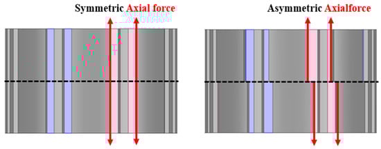
Figure 1.
Axial Force in Symmetric and Asymmetric Structures.
As illustrated in Figure 2, the generated axial magnetic force is transmitted through the shaft and directly applied to the bearings, creating additional mechanical load. This load does not contribute to torque production but increases mechanical stress and friction, which can shorten the bearing lifetime and may lead to premature failure.
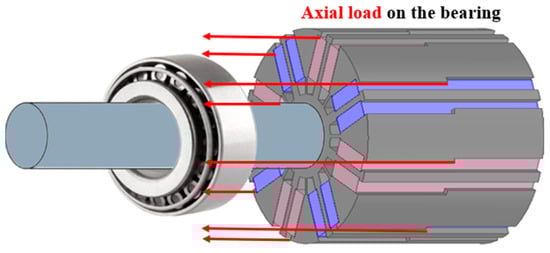
Figure 2.
Bearing Load Due to Axial Force.
Axial force is the electromagnetic force acting in the axial direction, which does not contribute to motor output but imposes excessive loads on the bearings, thereby shortening their lifetime and potentially causing early damage in the long term. In addition, an increase in axial force intensifies vibration and noise, and in applications requiring high-speed operation, such as electric vehicles, it is directly associated with the deterioration of noise, vibration, and harshness (NVH) performance. Therefore, a design that considers only cogging torque reduction is insufficient; thus, this study proposes a design methodology capable of simultaneously addressing both cogging torque and axial force issues, thereby contributing to the development of high-efficiency and high-reliability motors.
2. Fundamental Theory
2.1. Theory of Cogging Torque
Cogging torque originates from the variation in magnetic reluctance in the air gap caused by the arrangement of stator teeth and slots, and it is generated by the tendency of the rotor to align with the position of minimum reluctance. As the rotor moves, this torque alternates in the forward and reverse directions, exhibiting a periodic nature whose total sum over one electrical cycle converges to zero. Consequently, cogging torque is regarded as an undesirable component that produces no useful work, while inducing vibration and noise during motor operation and deteriorating control performance.
In general, cogging torque can be interpreted as the variation in magnetic energy with respect to the rotor angular position, and it can be expressed mathematically as follows [,,,]. Equation (1) defines the cogging torque as the rate of change in magnetic energy with respect to rotor displacement, representing the tendency of the rotor to move toward the position of minimum magnetic energy.
where denotes the cogging torque, represents the magnetic energy, and indicates the rotor displacement. Since the variation in magnetic energy mainly occurs in the air gap, cogging torque can be calculated by considering only the energy in the air-gap region. Cogging torque is independent of current and is determined by the magnetic field produced by the permanent magnets, which can be expressed using the magnetomotive force (MMF) function and the permeance function as follows. The magnetic energy in the air gap can be expressed in terms of the magnetomotive force and the air-gap permeance, as shown in Equations (2)–(4).
where denotes the permeability of free space, is the air-gap magnetomotive force (MMF) function, is the air-gap permeance, is the flux density, is the relative permeance, is the mechanical angle at the standstill position, is the stator stack length, is the stator outer diameter, and is the inner radius of the permanent magnet. By expanding the even functions and in Equation (2) into Fourier series, Equations (5) and (6) can be obtained.
where is the number of slots and is the number of poles, and due to the orthogonality of trigonometric functions, the frequency component affecting the air-gap energy is , which is the least common multiple (LCM) of and . Accordingly, the air-gap energy function is obtained as Equation (7).
According to Equation (1), by differentiating the air-gap energy obtained in Equation (7) with respect to the rotor angle, the final expression of cogging torque can be derived as Equation (8).
2.2. Theory of Axial Force
Section 2.1 discusses the cogging torque characteristics, which represent one of the key design considerations of the proposed motor. Following this, Section 2.2 addresses another important design factor, axial force, by providing its fundamental concepts. Since the proposed motor is designed with the advantage of simultaneously considering both cogging torque and axial force, a clear understanding of the mechanism and characteristics of axial force is essential. Therefore, Section 2.2 was supplemented with explanations regarding the types of forces generated in a general radial flux motor and the mechanism through which axial force occurs, thereby strengthening the theoretical continuity with the subsequent analysis.
In a radial flux motor, the generated forces can be categorized into radial, axial, and tangential components. Among these, only the tangential component contributes to effective work, while the radial and axial components are regarded as undesirable components that cause vibration and noise. As described earlier in Figure 1, motors with an axially symmetric structure exhibit a balanced flux distribution along the axial direction, resulting in the cancellation of axial force components so that the net axial force becomes negligible. However, when skew is applied, the internal flux distribution becomes asymmetric, causing an imbalance in the axial force components and consequently generating axial force. Considering these characteristics, the overall force inside the motor can be expressed as follows:
In Equations (9)–(11), denotes the permeability of free space, is the radial force, is the tangential force, and is the axial force.
2.3. Theory of Two-Segment Permanent Magnet Flux-Concentrated Motor
Figure 3 illustrates the configuration of a two-segment permanent magnet flux-concentrated spoke-type motor. The rotor consists of permanent magnets, which serve as the flux source, pole-pieces and I-cores placed between the magnets, bridges that mechanically support the pole-pieces, ribs that prevent magnet scattering, and barriers that suppress flux leakage to adjacent poles. The arrows indicate the magnetization direction. As shown in Figure 3, the spoke-type structure arranges the permanent magnets in the radial direction to concentrate the flux, thereby achieving high magnetic torque.
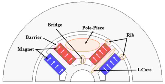
Figure 3.
Configuration of the two-segment permanent magnet flux-concentrated spoke-type motor.
Figure 4 shows the flux distribution of the segmented permanent magnet flux-concentrated motor, while Figure 5 presents the corresponding magnetic equivalent circuit based on it. The flux paths in Figure 4 can be classified into three categories.
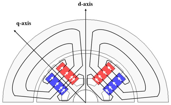
Figure 4.
Flux distribution and main flux paths of the two-segment permanent magnet Spoke-type motor.
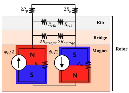
Figure 5.
Magnetic equivalent circuit of the two-segment permanent magnet Spoke-type motor.
The first path is where the flux generated from the permanent magnet passes through the pole-piece and the air gap, flows into the stator core, and then returns to the permanent magnet via the air gap and pole-piece. The second path is where the flux returns to the permanent magnet by passing between the ribs instead of the stator core. The third path is where the flux, rather than flowing toward the air gap, passes through the bridge and rotor back yoke before returning to the permanent magnet.
Among these, the second and third paths are leakage flux components that do not contribute to the air-gap flux. Such leakage flux occurs until the ribs and bridges become saturated, at which point their magnetic properties are similar to those of air. In contrast, the pole-piece, rotor back yoke, and stator core have large cross-sectional areas, resulting in relatively low saturation flux density; thus, their magnetic reluctances can be neglected when constructing the equivalent circuit. Accordingly, the equivalent circuit in Figure 5 is simplified to consist of the reluctances of the permanent magnet, air gap, bridge, and rib. Since the structure is symmetrical with respect to the d-axis, the equivalent circuit is expressed for a half pole-pair.
Here, denotes the reluctance of the air gap with a relative permeability of 1. is the reluctance of the permanent magnet with a relative permeability of approximately 1.05, slightly higher than that of air. Meanwhile, and represent the reluctances of the bridge and rib, respectively. As both are composed of ferromagnetic material, magnetic saturation occurs, and thus and exhibit nonlinear characteristics in the magnetic equivalent circuit.
3. Design Methodology of Motors with the Skew Factor Applied
3.1. Overview of Motor with Skew Factor Application
The asymmetric rib structure of the rotor can reduce cogging torque but inevitably induces axial force, which must be considered as an important design factor due to its impact on bearing load, vibration, and noise. To address this trade-off, this study introduces the concept of a skew factor, which adjusts the proportion of asymmetric and symmetric ribs, as illustrated in Figure 6. The skew factor enables simultaneous consideration of cogging torque and axial force, providing flexibility depending on the design objectives.
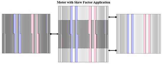
Figure 6.
Concept of the skew factor applied to the rotor structure for balancing cogging torque and axial force.
3.2. Design Parameters of Motor with Skew Factor Application
Figure 7 illustrates the design parameters of the motor for reducing cogging torque and axial force. Similarly to conventional flux-concentrating motors, the major design parameters considered in this study include the permanent magnet (PM) shape, ribs, bridges, PM embedding depth, rotor back yoke thickness, and shaft diameter. In general, when designing the rotor of a two-segment flux-concentrating motor, several factors must be comprehensively considered, such as the mechanical stiffness, leakage flux path, post-assembly magnetization characteristics, irreversible demagnetization, and overall motor performance.
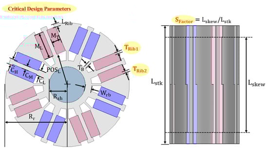
Figure 7.
Major design parameters of the motor with skew factor applied.
The iron core thickness located between adjacent magnets is a major factor influencing the reluctance torque. However, when the outer diameter of the rotor is limited, an increase in may reduce the PM volume; therefore, the optimal thickness should be determined by considering the ratio between the magnetic and reluctance torques. The lower core thickness and upper core thickness , positioned beneath and above the PMs, respectively, serve to mechanically support the magnets. However, can act as a leakage flux path during post-assembly magnetization, and thus it should be minimized within the range necessary for structural support. Similarly, may also become a leakage path and should therefore be kept as short as possible.
Increasing the PM length enlarges the PM cross-sectional area relative to the air-gap area, thereby enhancing the air-gap flux density. Nevertheless, excessive PM length deteriorates the post-assembly magnetization characteristics; hence, the PM length should be maximized only within the range that ensures sufficient magnetization performance. The PM thickness is another key variable that affects irreversible demagnetization, post-assembly magnetization, and air-gap flux density. Therefore, the PM thickness should be properly selected by balancing the magnetic and reluctance torque contributions. In addition, the bridge thickness fixes the pole piece while also serving as a leakage flux path. It should therefore be minimized as long as sufficient structural integrity is maintained. The parameters , , and represent the rotor outer radius, shaft radius, and rotor back-yoke thickness, respectively.
The aforementioned parameters correspond to the fundamental design variables of a conventional two-segment flux-concentrating PM motor. However, to simultaneously consider both cogging torque and axial force, additional design parameters must be introduced. Among these, the rib lengths and shown in Figure 7 are noteworthy, as they significantly affect the cogging torque characteristics.
In conventional flux-concentrating motors, the ribs merely function to prevent magnet scattering; in contrast, the proposed design employs asymmetric ribs so that the cogging torque peaks occur at different rotor positions, thereby reducing the overall resultant cogging torque.
Furthermore, the skew factor is an additional design variable introduced to control both cogging torque and axial force. The skew factor is defined as the ratio of the skew length to the total stack length , as expressed in Equation (12), and its value lies between 0 and 1. A higher (approaching 1) indicates a greater degree of skew, which amplifies the effect of the asymmetric ribs, whereas a lower (approaching 0) corresponds to a symmetric configuration without skew. Accordingly, the selection of serves as a key factor in determining the target levels of cogging torque and axial force. When minimizing cogging torque is prioritized, a larger is preferred; conversely, when axial force reduction is emphasized, a smaller is more suitable.
3.3. Design Process for Electric Machines Considering Cogging Torque and Axial Force
The design process of the skew-factor-applied electric machine, which simultaneously considers cogging torque and axial force, is illustrated step by step in Figure 8, Figure 9 and Figure 10.
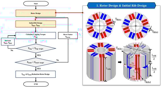
Figure 8.
Design process for rotor and initial rib configuration.
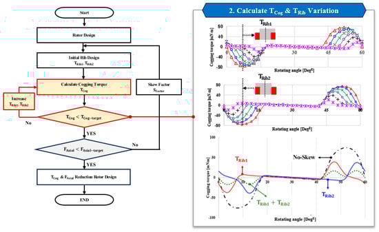
Figure 9.
Design process for cogging torque evaluation and rib adjustment.
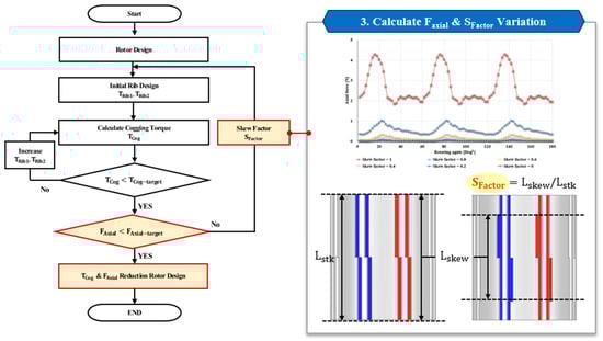
Figure 10.
Design process for axial force and skew factor optimization.
Figure 8 shows the asymmetric rib design method, in which the rotor is divided into two sections along the stack length to effectively separate the peak positions of cogging torque. Since cogging torque mainly arises from the variation in air-gap permeance due to slot openings, adjusting the rib length distribution alters the phase of the cogging torque waveform. By arranging the rib lengths of the two sections in opposite directions, a phase difference is introduced between their cogging torque components, resulting in a reduction in the overall cogging torque. In this process, and are designed in opposite orientations to maximize this effect.
Figure 9 illustrates the process of calculating and comparing the cogging torque with the target value. The rib length is iteratively adjusted, and the cogging torque is repeatedly evaluated until the desired reduction is achieved. Through this iterative process, the cogging torque can be gradually reduced. Once the target cogging torque is obtained, the axial force is analyzed to examine the influence of the asymmetric rib configuration on the axial magnetic characteristics.
Figure 10 presents the process of reducing the axial force by applying the skew factor. When the axial force exceeds the allowable limit, the skew factor is adjusted to alleviate the asymmetry of the axial magnetic flux, thereby reducing the axial force. The skew factor is varied, and the analysis is repeated until the axial force reaches the target level.
However, an excessive increase in the skew factor may alter the cogging torque characteristics; therefore, both parameters must be re-evaluated to achieve balanced performance. This iterative optimization continues until both the cogging torque and axial force reach their respective target values.
In summary, the optimal skew factor is determined by comprehensively considering the trade-off between cogging torque and axial force. When the reduction in axial force is prioritized, the skew factor is set to a larger value by increasing the proportion of the asymmetric-rib section, whereas a smaller skew factor is selected when cogging torque reduction is emphasized. By appropriately selecting the design variables according to the objective function, the final rotor design achieves simultaneous reductions in cogging torque and axial force.
4. Validation by Finite Element Analysis
4.1. Effect of Skew Factor on Cogging Torque
A skew factor of 1 indicates that 100% of the total stack length of the motor corresponds to the skewed region, whereas a skew factor of 0 represents a fully symmetrical structure without any skew. In other words, the skew factor is defined as the relative ratio of the skewed region to the total stack length. According to the results shown in Figure 11, the cogging torque varies with the skew factor, and it tends to decrease as the skew factor is reduced. This is because the skewed region with asymmetric ribs, which contributes to cogging torque reduction, becomes smaller. Therefore, in order to maximize the cogging torque reduction effect, it is desirable to set the skew factor as high as possible.
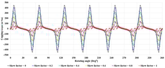
Figure 11.
Variation in Cogging Torque with Skew Factor.
4.2. Effect of Skew Factor on Axial Force
Figure 12 shows the variation in axial force with respect to the skew factor. In contrast to the cogging torque results presented earlier, the axial force increases as the skew factor becomes larger. This occurs because the asymmetry introduced by the skew serves as the main cause of axial force, resulting in greater axial force at higher skew factors.
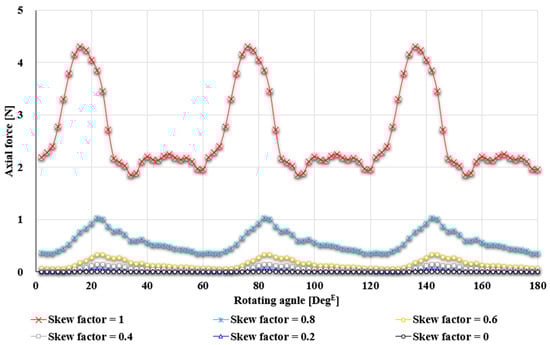
Figure 12.
Variation in axial force with Skew Factor.
4.3. Comparison of Cogging Torque and Axial Force with Skew Factor Variation
Figure 13 shows the comparison of cogging torque and axial force with respect to the skew factor. As the skew factor increases, cogging torque decreases while axial force increases; conversely, when the skew factor decreases, cogging torque increases and axial force decreases. This indicates that the selection of the skew factor has a critical influence on both components. Considering this relationship, it was confirmed that applying a skew factor of 0.8 is the most appropriate choice to simultaneously reduce cogging torque and axial force. However, if cogging torque reduction is prioritized, a larger skew factor should be applied, whereas a smaller skew factor is preferable when the suppression of axial force is emphasized.
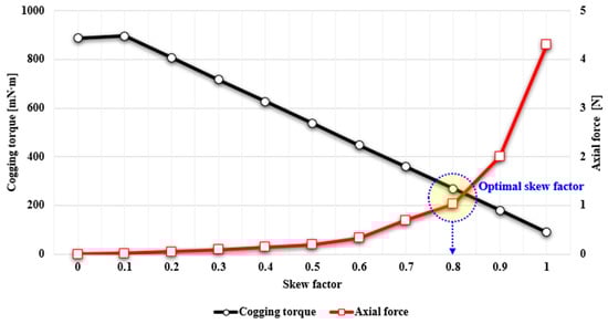
Figure 13.
Determination of the Optimal Skew Factor Considering Cogging Torque and Axial Force.
4.4. Comparative Analysis of Motor Types
To validate the feasibility of the proposed model, finite element analysis (FEA) was conducted on three motor types: a conventional symmetric motor, a motor with asymmetric ribs, and a motor with an applied skew factor. These motor types are illustrated in Figure 14, where (a) represents a conventional symmetric flux-concentrated motor, (b) a flux-concentrated motor with asymmetric ribs, and (c) a flux-concentrated motor with an optimal skew factor of 0.8. The analysis results are summarized in Table 1.
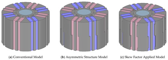
Figure 14.
Comparison of models with different rotor structures for cogging torque and axial force analysis.

Table 1.
Performance comparison of Spoke-type motor models with different rotor structures.
According to Table 1, the symmetric structure in model (a) yields zero axial force; however, the cogging torque is as high as 888.5 mNm. In contrast, model (b) with asymmetric ribs significantly reduces the cogging torque to 89.8 mNm compared with model (a), but the axial force increases to 4.3 N. Finally, model (c) with a skew factor of 0.8 exhibits a cogging torque of 268.9 mNm and an axial force of 1 N. This corresponds to a reduction in cogging torque of approximately 69.7% compared with model (a), and a reduction in axial force of about 76.7% compared with model (b).
These results confirm that applying an appropriate skew factor enables the design of flux-concentrated motors in which both cogging torque and axial force can be simultaneously reduced.
5. Prototype Fabrication and Experimental Evaluation
5.1. Overview of Prototype Fabrication and Evaluation
This section describes the prototype fabrication process and performance evaluation of the motor derived from the proposed design procedure. Although three design models were compared and analyzed through simulation, prototype fabrication was limited to a representative baseline model due to constraints in research scope and resources. For this model, performance tests including load, no-load, dielectric withstand, and insulation resistance measurements were conducted. In addition, a rotor magnetization test after assembly was carried out to assess mass-production feasibility. The experimental results were subsequently used to validate consistency with simulation outcomes.
5.2. Overview of Prototype Fabrication
5.2.1. Fabrication of the Magnetizing Yoke Prototype
Figure 15 illustrates the internal structure and final configuration of the fabricated magnetizing yoke. The yoke consists of eight teeth and a back yoke, among which four teeth are wound with coils to generate the magnetizing field. The remaining four teeth serve to prevent demagnetization of the already magnetized permanent magnets.
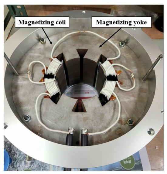
Figure 15.
Internal Structure and Winding Arrangement of the Magnetizing Yoke.
The coils were placed only on four teeth to concentrate the magnetizing field on specific permanent magnets, thereby improving the magnetization efficiency. As a result, two permanent magnets are magnetized in a single process, and thus a total of four magnetization steps are required to complete the magnetization of all permanent magnets in the eight-pole motor.
The winding employed AIW enamel copper wire with a diameter of 2.6 mm, and double-coated insulation wire was used to enhance dielectric performance. The detailed specifications of the magnetizing yoke and the winding are summarized in Table 2. The core of the magnetizing yoke was fabricated using 50PN470 (S18) material to minimize eddy-current effects. In addition, to prevent incomplete magnetization of the rotor’s upper permanent magnets caused by axial leakage flux, the lamination length of the magnetizing yoke was made 5 mm longer on each side than the lamination length of the motor.
Table 2.
Specifications of the magnetizing yoke and winding.
5.2.2. Fabrication of the Motor Prototype
Ferrite permanent magnets (grade 9) were employed in the fabrication of the motor prototype. Since the permanent magnets could not be manufactured in a single piece of 90 mm length, they were divided into 45 mm segments and subsequently inserted into the rotor core slots. The windings were made of F-class enameled copper wire, which is commonly applied in electric machines and provides thermal endurance of approximately 150 °C.
The stator was fabricated with a concentrated winding structure, and the rotor core was designed with fastening holes placed in regions where the magnetic influence is minimized to allow for bolt assembly. To reduce core losses, both the rotor and stator employed electrical steel sheets of grade 35PN230. The shaft was made of S45C material to ensure sufficient rigidity, and a keyway was machined between the rotor core and the shaft to prevent slippage and enhance mechanical stability.
In addition, an NTC (Negative Temperature Coefficient) thermistor sensor was embedded within the prototype winding for temperature monitoring. The rotor structure is shown in Figure 16, while the stator along with the Hall sensor is depicted in Figure 17, and the overall configuration of the fabricated motor prototype is presented in Figure 18. Furthermore, the key specifications are summarized in Table 3.
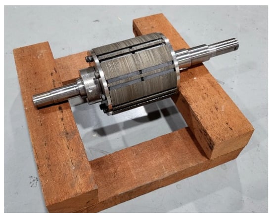
Figure 16.
Fabricated rotor of the Spoke-type motor prototype.
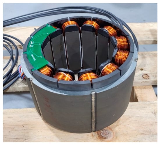
Figure 17.
Fabricated stator and winding configuration of the Spoke-type motor.
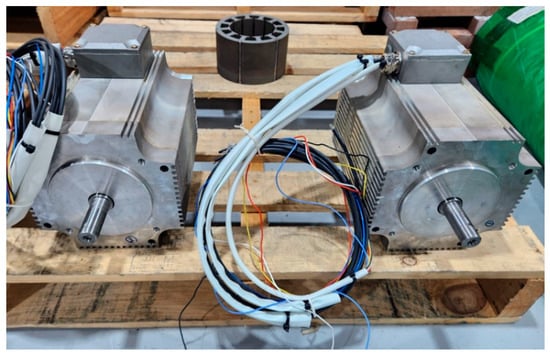
Figure 18.
Fully assembled Spoke-type motor prototype.
Table 3.
Specifications of the Motor Prototype.
5.3. Overview of Prototype Evaluation
This section describes the prototype fabrication and performance evaluation of the motor derived from the proposed design procedure. The performance tests included load, no-load, dielectric withstand, and insulation resistance measurements, and an additional rotor magnetization test after assembly was conducted to verify mass-production feasibility.
5.3.1. No-Load Back-EMF Test
The no-load back electromotive force (EMF) was measured by driving the motor at 1800 rpm, with the terminals open, using a dynamometer. The waveform of the measured line-to-line back EMF is shown in Figure 19, and the root-mean-square (RMS) values from both analysis and experiment are summarized in Table 4. The analytical result was 246.1 , while the experimental result was 245.9 , showing an error of only about 0.1%, which indicates an excellent agreement between the two results.
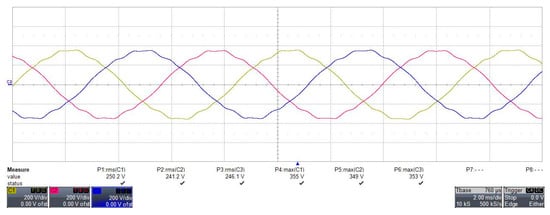
Figure 19.
No-load back-EMF waveform at 1800 rpm.
Table 4.
No-load back-EMF results at 1800 rpm.
5.3.2. Load Test
To evaluate the performance of the prototype, a load test was conducted. In this test, torque, output power, efficiency, speed, and current were measured, and the results are presented in Figure 20. The horizontal axis of the figure represents torque, while the vertical axis corresponds to efficiency, voltage, output power, current, and speed. At the rated speed of 1800 rpm, a torque of 8 Nm and an output power of 1.5 kW were obtained, with an efficiency of 92.84% under the rated load condition.
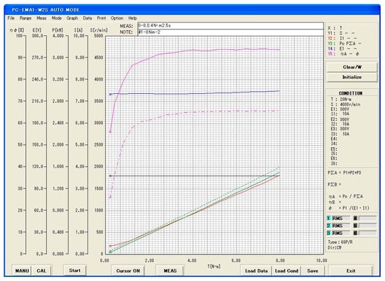
Figure 20.
Load performance test results of the motor prototype.
5.3.3. Comparison Between Simulation and Experimental Results
To verify the performance of the prototype, the simulation results for torque, efficiency, and output power were compared with the experimental results. Figure 21 presents the torque characteristics, Figure 22 shows the efficiency characteristics, and Figure 23 illustrates the output power characteristics, each comparing the simulation and experimental outcomes. The numerical comparison is summarized in Table 5.
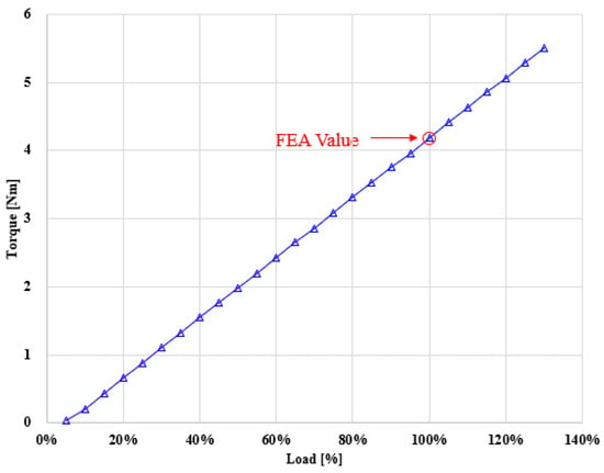
Figure 21.
Load–torque characteristics of the motor prototype.
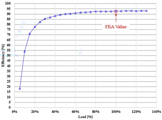
Figure 22.
Load–efficiency characteristics of the motor prototype.
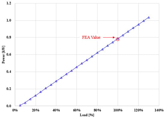
Figure 23.
Load–power characteristics of the motor prototype.
Table 5.
Relative error between simulation and experimental results.
The comparison results revealed that the differences between the simulation and experiment were less than 2% in all cases. In particular, the measured torque was 4.19 Nm, while the analytical value was 4.17 Nm, corresponding to an error rate of 0.48%. The output power was 787.8 W in the experiment and 778.8 W in the analysis, showing a deviation of about 1.14%. The efficiency was measured as 92.84% and calculated as 92.31%, with only a 0.27% difference. These results demonstrate that the analytical model accurately reflects the operating characteristics of the fabricated prototype, thereby confirming the excellent agreement between the simulation predictions and the experimental validation.
6. Conclusions
In this study, a novel design approach was proposed to simultaneously mitigate the conflicting issues of cogging torque and axial force in motor design. The proposed optimization strategy adjusts the skew ratio according to the target performance, thereby overcoming the limitations of conventional skew designs and achieving a balanced reduction in both parameters. Simulation results confirm that the proposed design effectively reduces torque ripple and cogging torque, leading to lower vibration and noise levels and improved overall efficiency compared with conventional motor designs.
The proposed method provides a practical and scalable design guideline for developing high-performance, low-noise, and energy-efficient motors. Owing to its adaptability, the approach can be extended to various industrial and commercial motor systems, including larger-capacity applications. These findings are expected to contribute to further improvements in motor system quality and competitiveness in future developments.
Author Contributions
Conceptualization, M.-J.J.; methodology, M.-J.J. and D.-H.J.; software, S.-H.L.; validation, M.-J.J., D.-H.J. and D.-W.N.; formal analysis, M.-J.J. and S.-H.L.; investigation, M.-J.J. and D.-W.N.; resources, W.-H.K.; data curation, S.-H.L.; writing—original draft preparation, M.-J.J.; writing—review and editing, M.-J.J. and W.-H.K.; visualization, S.-H.L.; supervision, W.-H.K.; project administration, M.-J.J. and W.-H.K.; funding acquisition, W.-H.K. All authors have read and agreed to the published version of the manuscript.
Funding
This work was supported by the Technology Development Program (RS-2024-00470254) funded by the Ministry of SMEs and Startups (MSS, Korea) and the Technology Innovation Program (RS-2024-00469146, Development of Robot Motor (Motor, Driver) and Encoder Technology Using Functional Safety Design Technology) funded by the Ministry of Trade, Industry & Energy (MOTIE, Korea).
Data Availability Statement
The datasets presented in this article are not readily available because the data are part of an ongoing research project and cannot be made publicly available at this stage.
Conflicts of Interest
The authors declare no conflict of interest.
References
- Chung, S.-U.; Moon, S.-H.; Kim, D.-J.; Kim, J.-M. Development of a 20-Pole–24-Slot SPMSM With Consequent Pole Rotor for In-Wheel Direct Drive. IEEE Trans. Ind. Electron. 2016, 63, 302–309. [Google Scholar] [CrossRef]
- Fang, L.; Jung, J.-W.; Hong, J.-P.; Lee, J.-H. Study on High-Efficiency Performance in Interior Permanent-Magnet Synchronous Motor With Double-Layer PM Design. IEEE Trans. Magn. 2008, 44, 4393–4396. [Google Scholar] [CrossRef]
- Ma, Q.; El-Refaie, A.; Lequesne, B. Low-Cost Interior Permanent Magnet Machine with Multiple Magnet Types. IEEE Trans. Ind. Appl. 2020, 56, 1452–1463. [Google Scholar] [CrossRef]
- Song, C.-H.; Song, I.-S.; Shin, H.-S.; Lee, C.-H.; Kim, K.-C. A Design of IPMSM for High-Power Electric Vehicles With Wide-Field-Weakening Control Region. IEEE Trans. Magn. 2022, 58, 8700305. [Google Scholar] [CrossRef]
- Rasmussen, K.F.; Davies, J.H.; Miller, T.J.E.; McGelp, M.I.; Olaru, M. Analytical and Numerical Computation of Air-Gap Magnetic Fields in Brushless Motors with Surface Permanent Magnets. IEEE Trans. Ind. Appl. 2000, 36, 1547–1554. [Google Scholar] [CrossRef]
- Abbasian, M.; Moallem, M.; Fahimi, B. Double-Stator Switched Reluctance Machines (DSSRM): Fundamentals and Magnetic Force Analysis. IEEE Trans. Energy Convers. 2010, 25, 589–597. [Google Scholar] [CrossRef]
- Fiedler, J.O.; Kasper, K.A.; De Doncker, R.W. Calculation of the Acoustic Noise Spectrum of SRM Using Modal Superposition. IEEE Trans. Ind. Electron. 2010, 57, 2939–2945. [Google Scholar] [CrossRef]
- Ryan, M.J.; Brumsickle, W.E.; Lorenz, R.D. Control Topology Options for Single-Phase UPS Inverters. IEEE Trans. Ind. Appl. 1997, 33, 493–501. [Google Scholar] [CrossRef]
- Luo, F.L.; Ye, H. Positive Output Multiple-Lift Push-Pull Switched-Capacitor Luo-Converters. IEEE Trans. Ind. Electron. 2004, 51, 594–602. [Google Scholar] [CrossRef]
- Ferrari, M.; Bianchi, N.; Fornasiero, E. Analysis of Rotor Saturation in Synchronous Reluctance and PM-Assisted Reluctance Motors. IEEE Trans. Ind. Appl. 2015, 51, 169–177. [Google Scholar] [CrossRef]
- Geng, W.; Wang, J.; Li, L.; Guo, J. Design and Multiobjective Optimization of a New Flux-Concentrating Rotor Combining Halbach PM Array and Spoke-Type IPM Machine. IEEE/ASME Trans. Mechatron. 2023, 28, 257–266. [Google Scholar] [CrossRef]
- Hua, Y.; Wang, C.; Liu, Y.; Zhang, Z.; Kong, X.; Han, J. Comparative Study of High Torque Density Spoke-Type PM In-Wheel Motors for Special Vehicle Traction Applications. IEEE Trans. Ind. Appl. 2022, 58, 1952–1962. [Google Scholar] [CrossRef]
- Wang, J.; Geng, W.; Li, Q.; Li, L.; Zhang, Z. A New Flux-Concentrating Rotor of Permanent Magnet Motor for Electric Vehicle Application. IEEE Trans. Ind. Electron. 2022, 69, 10882–10892. [Google Scholar] [CrossRef]
- Chen, Q.; Xu, G.; Zhai, F.; Liu, G. A Novel Spoke-Type PM Motor With Auxiliary Salient Poles for Low Torque Pulsation. IEEE Trans. Ind. Electron. 2020, 67, 4762–4773. [Google Scholar] [CrossRef]
- Seok, C.-H.; Yoon, S.-Y.; Choi, H.-S.; Lee, H.-Y.; Seo, J. Analysis and Modeling of Axial Leakage for Spoke-Type Hybrid Permanent Magnet Machines. IEEE Access 2023, 11, 6385–6393. [Google Scholar] [CrossRef]
- Jung, J.-W.; Jung, D.-H.; Lee, J. A Study on the Design Method for Improving the Efficiency of Spoke-Type PMSM. IEEE Trans. Magn. 2023, 59, 8200205. [Google Scholar] [CrossRef]
- Jeong, M.-J.; Lee, K.-B.; Pyo, H.-J.; Nam, D.-W.; Kim, W.-H. A Study on the Shape of the Rotor to Improve the Performance of the Spoke-Type Permanent Magnet Synchronous Motor. Energies 2021, 14, 3758. [Google Scholar] [CrossRef]
- Bianchi, N.; Bolognani, S. Design Techniques for Reducing the Cogging Torque in Surface-Mounted PM Motors. IEEE Trans. Ind. Appl. 2002, 38, 1259–1265. [Google Scholar] [CrossRef]
- Zhu, L.; Jiang, S.Z.; Zhu, Z.Q.; Chan, C.C. Analytical Methods for Minimizing Cogging Torque in Permanent-Magnet Machines. IEEE Trans. Magn. 2009, 45, 2023–2031. [Google Scholar] [CrossRef]
- Hao, W.; Wang, Y. Comparison of the Stator Step Skewed Structures for Cogging Force Reduction of Linear Flux Switching Permanent Magnet Machines. Energies 2018, 11, 2172. [Google Scholar] [CrossRef]
- Jin, M.J.; Wang, Y.; Shen, J.X.; Luk, P.C.K.; Fei, W.Z.; Wang, C.F. Cogging Torque Suppression in a Permanent-Magnet Flux-Switching Integrated-Starter–Generator. IET Electr. Power Appl. 2010, 4, 575–584. [Google Scholar] [CrossRef]
- Sikder, C.; Husain, I.; Ouyang, W. Cogging Torque Reduction in Flux-Switching Permanent-Magnet Machines by Rotor Pole Shaping. IEEE Trans. Ind. Appl. 2015, 51, 3609–3619. [Google Scholar] [CrossRef]
- Yamazaki, K.; Matsumoto, M. 3-D Finite Element Meshing for Skewed Rotor Induction Motors. IEEE Trans. Magn. 2015, 51, 2348568. [Google Scholar] [CrossRef]
- Hribernik, B.; Hamler, A.; Kreca, B.; Trlep, M. Numerical Estimation of the Field Error of Small Single and Double Sheet Testers. IEEE Trans. Magn. 1998, 34, 3276–3279. [Google Scholar] [CrossRef]
- Tenhunen, A.; Arkkio, A. Modelling of Induction Machines with Skewed Rotor Slots. IEE Proc. Electr. Power Appl. 2001, 148, 67–73. [Google Scholar] [CrossRef]
- Gao, F.; Wang, Q.; Zou, J.; Xu, Y. Development of Equivalent 2-D Finite-Element Models for Accurate Prediction of Thrust Force in Permanent Magnet Lead Screws. IEEE Trans. Magn. 2017, 53, 2703844. [Google Scholar] [CrossRef]
- Paul, C.R. Solution of the Transmission-Line Equations for Lossy Conductors and Imperfect Earth. Proc. Inst. Electr. Eng. 1975, 122, 161–167. [Google Scholar] [CrossRef]
- Park, G.-J.; Kim, Y.-J.; Jung, S.-Y. Design of IPMSM Applying V-Shape Skew Considering Axial Force Distribution and Performance Characteristics According to the Rotating Direction. IEEE Trans. Appl. Supercond. 2016, 26, 2543267. [Google Scholar] [CrossRef]
Disclaimer/Publisher’s Note: The statements, opinions and data contained in all publications are solely those of the individual author(s) and contributor(s) and not of MDPI and/or the editor(s). MDPI and/or the editor(s) disclaim responsibility for any injury to people or property resulting from any ideas, methods, instructions or products referred to in the content. |
© 2025 by the authors. Licensee MDPI, Basel, Switzerland. This article is an open access article distributed under the terms and conditions of the Creative Commons Attribution (CC BY) license (https://creativecommons.org/licenses/by/4.0/).