Abstract
In response to grid peak-shaving requirements under renewable energy integration, this study investigates the thermodynamic performance of a 300 MW adiabatic compressed air energy storage (A-CAES) system, with a focus on optimizing electro-thermal efficiency through parametric analysis. A detailed thermodynamic model was developed to systematically evaluate the effects of compression/expansion stage configurations (2–4 stages), pressure ratios (4–6), and inter-stage outlet temperatures (120–190 °C) on system performance. The results demonstrate that variable-pressure operation improves round-trip efficiency by a 1.8% per unit compression ratio increase, while optimized inter-stage cooling (150 °C) reduces exergy destruction by 22.5%. Thermal efficiency monotonically improves with additional expansion stages, whereas electrical efficiency peaks at three stages (70%) before declining due to parasitic losses. Exergy analysis reveals that compressors and turbines account for 65% of total destruction, emphasizing the need for enhanced heat exchanger design. These findings provide actionable insights for balancing efficiency gains with operational constraints in large-scale A-CAES deployment.
1. Introduction
By 2030, renewable energy is projected to account for 36% of global energy supply, with energy storage systems playing a crucial role in enhancing efficiency and enabling integration by mitigating fluctuations []. These technologies are categorized by storage type—mechanical (e.g., compressed air, flywheels, pumped hydro), electrochemical (e.g., lead-acid, lithium-ion batteries, flow cells, fuel cells), electrical (e.g., capacitors, supercapacitors, magnetic storage), and thermal (e.g., phase change materials, cryogenic storage) []. Due to their diversity, they are further subdivided, and in certain cases, cross-category integration is possible, such as by incorporating thermal storage into compressed air energy storage (CAES) systems.
Compressed Air Energy Storage (CAES), a long-duration energy storage technology, is a key solution for mitigating the intermittency of and fluctuations in renewable power generation. It is expected to facilitate the broader integration of renewable energy sources []. Referring to Figure 1, the CAES concept is derived from the gas turbine cycle but operates with the compressor and turbine stages separated. During the charging phase, off-peak electricity compresses air; the resulting compression heat is stored in a Thermal Energy Storage (TES) system. During discharge, the stored air is released and heated—either by burning fuel or using the stored thermal energy—before expanding through a turbine to generate electricity []. The compressed air is typically stored in underground caverns or above-ground vessels [,]. While pumped storage power plants remain the dominant technology in the field of electrical energy storage, CAES is poised to play a significant role in future grid stability solutions due to the challenges associated with constructing new large-capacity energy storage facilities. With its unique combination of large storage capacity and long discharge duration, CAES offers exceptional grid-scale flexibility, effectively complementing intermittent renewable sources such as wind and solar.
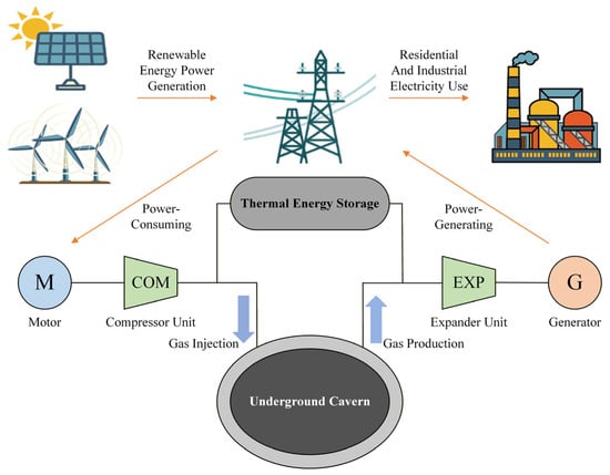
Figure 1.
Components of the CAES system.
Recent advancements in adiabatic CAES (A-CAES) variants have achieved greater efficiency by capturing and reusing compression heat, thereby eliminating dependence on fossil fuels. In recent years, several studies have demonstrated that the integration of high-temperature thermal-energy storage and optimized heat-exchange pathways enables A-CAES systems to fully replace natural-gas-based reheating with internally recovered compression heat. For example, biomass-assisted CAES configurations and solar-assisted liquid-piston CAES concepts have shown that renewable heat sources or stored compression heat can independently sustain the reheating process, thereby achieving complete fossil-fuel elimination. As power systems worldwide contend with increasing renewable penetration and decarbonization pressures, CAES emerges as a technically mature and geographically flexible storage option. It provides essential grid services, including peak shaving, frequency regulation, and renewable energy time-shifting, making it an indispensable component of sustainable energy infrastructure.
Research teams globally are intensively investigating the mechanistic effects of key components on the overall electricity-to-electricity conversion efficiency of A-CAES systems. For instance, Li et al. [] proposed an innovative hybrid system that integrates an organic Rankine cycle (ORC), solar thermal collectors, and a CAES system, achieving remarkable performance metrics with an electrical efficiency of 24.63%, energy efficiency of 86.96%, and exergy efficiency of 67.57%. Similarly, Yao et al. [] developed an integrated system that couples CAES with chemical energy storage, revealing that the operating parameters of compressors and gas turbines significantly influence both exegetic and economic performance indicators, with a round-trip efficiency reaching 42.96%.
Zeng et al. [] developed a thermo-moisture-fluid dynamic (TMFD) model to simulate the hygrothermal environment in CAES salt caverns and assess its impact on system performance, which shows that phase change reactions raise cavern temperature by 0.61 °C while stabilizing capacity, discharge liquefaction slightly improves round-trip efficiency, and accumulated liquefaction (646.11 kg/cycle) may reduce cavern volume and storage capacity by 5.01% and 6.23% over 30 years—an issue addressable by reducing inlet humidity.
Migliari et al. [] presented an integrated photovoltaic-hydrogen-compressed air energy storage (PV-H2-CAES) system specifically designed to accommodate additional intermittent renewable sources in already saturated power grids. Through component optimization and a novel energy management strategy, the system demonstrates significant performance improvements: it reduces photovoltaic curtailment from approximately 50% to just 4% annually, achieves overall system efficiencies of up to 62%, and provides valuable inertial power support during up to 20% of nighttime operating hours.
Khalafian et al. [] sized a hybrid renewable islanded system for combined electricity and heat supply, and the results show that compressed air storage reduces planning costs by 7.7% compared to batteries and 12.9% compared to hydrogen storage, while the combined energy provision increases costs by about 57% versus electricity-only systems. Furthermore, Jafarizadeh et al. [] investigated the interaction between multi-stage compression/expansion processes and industrial temperature classifications in CAES systems, with a particular focus on their impact on production costs. Through exergoeconomic analysis of three Advanced Adiabatic CAES (AA-CAES) configurations—designated as Low-, Medium-, and High-Temperature systems—their research establishes that the medium-temperature variant represents the most favorable operational regime for CAES implementation, as determined by multi-objective optimization.
Adib et al. [] systematically reviewed the integration of wind turbines with compressed air energy storage (CAES) systems during charging operations. Their analysis concluded that the intermittent nature of wind power leads to more pronounced operational fluctuations in wind-driven CAES systems compared to conventional configurations, necessitating specialized design and control strategies to address these dynamic characteristics. In a subsequent dynamic analysis, Adib et al. [] investigated a coupled wind-CAES system under off-design conditions, proposing a part-load operational framework. Their results demonstrate that this integrated system significantly reduces average daily total costs and CO2 emissions by 69% and 76%, respectively, presenting a viable, cost-effective, and reliable energy solution for remote applications.
In A-CAES systems, the parameters of different components within the process flow significantly affect overall system efficiency and performance []. This study focuses on a 300 MW A-CAES system, establishing a comprehensive thermodynamic model. Under consistent baseline initial conditions, we systematically investigate the influence of key parameters—including stage number, compression ratio, and outlet temperature—on system efficiency by varying these operational variables. The outcomes of this research aim to provide guidance for system design configuration and performance optimization.
To address the above research gaps, this study develops an integrated multi-parameter coupling framework for a 300 MW A-CAES system, enabling simultaneous evaluation of pressure-ratio scheduling, staged compression/expansion configuration, and inter-stage thermal-management strategies. Unlike previous studies that investigate these parameters independently, the proposed approach uncovers several previously unreported system-level behaviors, including: (i) a monotonic electro-thermal efficiency enhancement linked to coordinated pressure-ratio optimization; (ii) an optimal inter-stage temperature window (150–160 °C) that minimizes system-wide exergy destruction; (iii) a non-monotonic efficiency response revealing a three-stage expansion optimum; and (iv) a component-level attribution of avoidable and endogenous exergy losses based on an advanced exergy-analysis methodology. These contributions provide new insights and quantitative design guidelines for large-scale A-CAES engineering practice.
2. System Design Process
The adiabatic compressed air energy storage (A-CAES) system facilitates energy storage through multi-stage compression with intercooling. During the compression phase, thermal energy generated is stored in a thermal storage device via heat exchange media, while the high-pressure air is retained in an air storage reservoir.
Figure 2 illustrates the process schematic of an A-CAES system employing medium-temperature thermal storage, featuring a four-stage compression and three-stage expansion configuration. The compression phase operates under constant pressure for the first three compressors, which are equipped with dual intercooling stages—first for thermal storage and subsequently for heat rejection. The fourth compressor functions in variable-frequency sliding-pressure mode with a single intercooling stage.
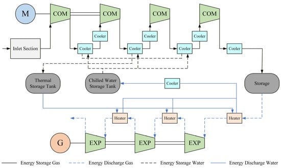
Figure 2.
Process flow diagram of an adiabatic compressed air energy storage (A-CAES) system.
In the expansion phase, three series-connected turbines are utilized, operating under a “throttle-first-then-slide” strategy. Each turbine is outfitted with upstream preheaters to optimize thermal energy utilization during power generation. This comprehensive configuration enhances the overall efficiency and effectiveness of the A-CAES system in converting stored energy into electrical power.
This study primarily analyzes the influence of stage count, compression ratio, and outlet temperature on system efficiency, leading to the following specifications and simplifications for the modeling process:
- (1)
- Air is treated as an ideal dry gas, with thermodynamic properties derived from the REFPROP database for dry air;
- (2)
- The model assumes negligible pipeline pressure losses and disregards heat dissipation within the system;
- (3)
- The gas storage reservoir is maintained at a constant temperature throughout both the charging and discharging processes;
- (4)
- Energy consumption during the start-stop phases of compressors and turbines is not considered, and equipment efficiency under off-design conditions is assumed to remain constant;
- (5)
- Auxiliary system energy consumption and its associated efficiency impacts fall outside the scope of this research.
The rationality of this constant-temperature assumption is based on the engineering fact that salt cavern storage reservoirs exhibit excellent thermal stability within limited pressure fluctuation ranges. Within the 7–10 MPa pressure interval defined in this study, coupled with the significant thermal inertia of salt caverns, the theoretical temperature fluctuation amplitude has negligible impact on system performance calculations. Thus, this simplification is therefore justified.
It is worth emphasizing that the gas storage reservoir maintains a constant temperature during both charging and discharging processes, as relevant parameters were preconfigured in the simulation software prior to modeling. This constant-temperature condition serves as a fundamental prerequisite for subsequent experimental validation, thereby justifying the assumption. Furthermore, temperature variations in the reservoir are deemed negligible based on pressure-temperature curve analysis when pressure fluctuates within the 7–10 MPa range.
3. System Mathematical Model
In addition to establishing the thermodynamic model, this study incorporates a methodological innovation by integrating thermal, electrical, and exergy analyses within a unified coupling framework. A multi-cycle exergy-assessment approach—comprising the actual, optimal, and hybrid thermodynamic cycles—is adopted to distinguish avoidable from unavoidable and endogenous from exogenous exergy destruction. This enables a deeper understanding of component-level irreversibilities beyond conventional exergy analysis. Furthermore, a dual-platform REFPROP–UniSim co-simulation architecture is employed to enhance property accuracy and process-level fidelity, thereby providing a more realistic representation of variable-pressure operation.
The adiabatic compressed air energy storage (A-CAES) system is primarily composed of compressors, air turbines, thermal storage systems, heat exchangers, and air storage reservoirs. The key system parameters are summarized in Table 1.

Table 1.
Key system parameters.
3.1. Compressor
During the energy storage phase, ambient air undergoes multi-stage compression with intercooling, transforming into high-pressure compressed air while adhering to the principles of adiabatic compression.
The specific enthalpy of air at the outlet of each compressor stage is:
,: the specific enthalpy of air at the inlet and outlet of the i-th stage compressor; : the isentropic specific enthalpy of air at the given pressure ratio of the i-th stage compressor; : the isentropic efficiency of the compressor.
The power consumption of each compressor stage is:
: the power consumption of the i-th stage compressor; : the mass flow rate of air at the compressor inlet; : the compressor motor efficiency; : the compressor mechanical efficiency.
3.2. Air Turbine
The specific enthalpy of air at the outlet of each turbine stage is:
: the specific enthalpy of air at the inlet and outlet of the i-th stage air turbine; : the isentropic specific enthalpy of air at the given pressure ratio of the i-th stage air turbine; : the isentropic efficiency of the air turbine.
The power generation of each air turbine stage is:
: the power generation of the i-th stage air turbine; : the mass flow rate of air at the air turbine inlet; : the generator efficiency of the air turbine; : the mechanical efficiency of the air turbine.
3.3. Heat Exchanger
During the energy storage process, the compressor compresses air into high-temperature, high-pressure gas, which is subsequently cooled in heat exchangers. For the outlets of Compressor Stages 1 to 3, a two-stage cooling approach is employed. The first cooling stage facilitates thermal energy storage, allowing for precise control of the heat storage temperature. In contrast, the second cooling stage does not store heat; instead, it regulates the inlet temperature of the subsequent compressor stage by controlling the cooling water flow rate. At the outlet of Compressor Stage 4, the cooler also does not store heat but ensures that the compressed air entering the storage reservoir is maintained at an appropriate temperature.
The thermal storage capacity of the first-stage cooler for each compressor stage is:
: the heat absorbed from the high-temperature air by the first-stage cooler of the i-th compressor; : the mass flow rate of the stored hot water in the i-th compressor; : the average specific heat capacity at constant pressure of the stored hot water in the i-th compressor; : the outlet and inlet temperatures of the stored hot water for the first-stage cooler of the i-th compressor.
The cooling capacity of the second-stage cooler for each compressor stage is:
: the cooling capacity of the second-stage cooler of the i-th compressor; : the mass flow rate of the cooling water in the i-th compressor; : the average specific heat capacity at constant pressure of the cooling water in the i-th compressor; : the outlet and inlet temperatures of the cooling water for the second-stage cooler of the i-th compressor.
During the energy discharge process, the compressed air extracted from the storage reservoir passes through heaters before entering each turbine stage, where it absorbs the compression heat stored during the charging phase to enhance turbine efficiency.
The heat release capacity of the expansion-side heater is:
: the heat released by the i-th expansion-side heater; : the mass flow rate of the stored hot water in the i-th expansion-side heater; : the average specific heat capacity at constant pressure of the stored hot water in the i-th expansion-side heater; : the outlet and inlet temperatures of the stored hot water for the i-th expansion-side heater.
3.4. System Performance Indicators
The full-load power consumption of the air compressor is:
: Gas storage reservoir pressure, in megapascals (MPa); : Enthalpy values at the inlet and outlet of the i-th stage compressor, determined by look-up tables, in kilojoules per kilogram (kJ/kg); : Air mass flow rate of the compressor, in kilograms per second (kg/s); Nc: Designed number of stages for the air compressor; tc: Operating duration of the air compressor, in hours (h); : Total electricity consumption during the energy storage process under full operating conditions, in kilowatt-hours (kW·h).
The full-load power generation of the expansion turbine is:
: Expander pressure, in megapascals (MPa); : Enthalpy values at the inlet and outlet of the i-th stage expander, in kilojoules per kilogram (kJ/kg); : Air mass flow rate of the expander, in kilograms per second (kg/s); Nt: Designed number of stages for the air expander; ts: Operating duration of the air expander, in hours (h); : Total power generation during the energy release process under full operating conditions, in kilowatt-hours (kW·h).
The full-load plant power consumption during compressed energy storage process is:
: Electrical power consumption of auxiliary equipment during the compression energy storage process under full operating conditions, in kilowatts (kW); : Operating duration of auxiliary equipment during the compression energy storage process under full operating conditions, in hours (h); : Plant electricity consumption during the compression energy storage process under full operating conditions, in kilowatt-hours (kW·h).
The full-load plant power consumption during expansion energy discharge process is:
: Electrical power consumption of auxiliary equipment during the expansion energy release process under full operating conditions, in kilowatts (kW); : Operating duration of auxiliary equipment during the expansion energy release process under full operating conditions, in hours (h); : Plant electricity consumption during the expansion energy release process under full operating conditions, in kilowatt-hours (kW·h).
The round-trip electrical efficiency is:
: Cycle electrical efficiency, unit: %.
Upon completion of the system design process and mathematical modeling, it is essential to analyze the innovations of this research. This study demonstrates significant innovative value in the following aspects:
- Methodological Innovation
A unified thermal-electrical-exergy coupling analysis is established, which, for the first time, links pressure-ratio scheduling, staged compression/expansion architecture, and inter-stage thermal management within a single analytical framework. This is enabled by an advanced three-cycle exergy-decomposition method (actual/optimal/hybrid cycles), allowing for the visualization and attribution of avoidable, unavoidable, endogenous, and exogenous exergy losses-an analytical depth not achieved in previous A-CAES literature.
- 2.
- Technical Pathway Innovation
A variable-pressure-ratio strategy combined with multi-stage intercooling and interstage reheating is introduced to decouple compression temperature rise from pressure elevation, revealing new monotonic and non-monotonic optimization laws (e.g., efficiency gain per unit pressure ratio, optimal expansion-stage count). Furthermore, a graded multi-temperature-zone thermal storage structure is proposed to achieve precise energy-grade matching and cascade heat utilization, which has not been quantitatively addressed in prior works.
- 3.
- Engineering Application Innovation
A dual-platform REFPROP-UniSim co-simulation architecture is constructed to ensure high-fidelity modeling of real-gas properties and process-level interactions. To the best of our knowledge, no prior A-CAES study has integrated these two platforms for rigorous, engineering-oriented coupling analysis, enabling more realistic prediction of variable-pressure operation performance.
It should be noted that detailed operational data from commercial A-CAES plants are generally not publicly available, and therefore a quantitative model-to-plant validation cannot be performed at this stage. The present study thus focuses on mechanism-based modeling supported by well-established thermophysical libraries (REFPROP) and an industrial process simulator (UniSim). The predicted thermodynamic trends show qualitative consistency with documented characteristics of existing CAES systems reported in the literature. Quantitative validation using experimental or industrial data will be included in future work as such data become accessible.
4. Research Results and Analysis
The electro-thermal performance analysis of the system aims to optimize overall efficiency through a rationally designed compression-expansion architecture. This analysis employs both static and dynamic methods while adhering to thermodynamic laws, equipment limitations, and operational constraints []. The study focuses on pressure ratios, air outlet temperatures, and compression/expansion stages, utilizing steady-state thermodynamic calculations alongside transient process simulations. These approaches examine energy-grade matching characteristics across various thermal storage temperature zones, exergy loss distribution patterns during compression and expansion processes, and dynamic response features under variable operating conditions [].
Additionally, the research establishes a multi-objective evaluation framework that incorporates efficiency, economic viability, and reliability. Intelligent optimization algorithms are then applied to identify the optimal solutions for electro-thermal performance. The findings provide a theoretical foundation and technical guidance for the design optimization and operational dispatch of energy storage systems.
4.1. Analysis of the Impact of Compression/Expansion Ratio on System Performance
The operational control strategies for CAES systems consist fundamentally of constant-pressure and variable-pressure ratio modes, distinguished by their respective pressure regulation approaches. During the charging phase, constant-pressure operation maintains a fixed discharge pressure at the final-stage compressor, while variable-pressure mode dynamically adjusts the outlet pressure to align with real-time reservoir conditions. Similarly, during discharge, constant-pressure control stabilizes turbine inlet pressure through throttling valves, in contrast to the sliding pressure strategy of variable-pressure operation, which adapts to system demands []. These complementary approaches facilitate tailored performance optimization across different operational scenarios in CAES applications.
From an operational perspective, the variable-pressure ratio mode demonstrates significant technical advantages. This approach optimizes the compression process during energy storage to reduce overall power consumption and effectively minimizes throttling losses during energy discharge, resulting in notable efficiency improvements. However, this operational mode necessitates more sophisticated control systems and regulation equipment, including variable-frequency drives, fast-response control valves, and advanced control algorithms, which can increase initial capital costs.
Consequently, practical engineering applications must carefully balance system efficiency gains against additional investment costs through comprehensive techno-economic evaluations to determine the optimal control strategy. The choice of operational approach not only affects technical performance but also directly influences the project’s economic viability, making it a critical consideration in the design of compressed air energy storage systems. This decision requires a multidimensional analysis of both thermodynamic benefits and financial implications to arrive at the most sustainable solution.
This leads to the first key factor influencing the system’s electro-thermal performance in our study: the compression-to-expansion ratio. Taking a three-stage compression and three-stage expansion system as an example, we set the initial conditions and calculation parameters. As the expansion ratio in our model varies with the compression ratio, we employ the control variable method to systematically adjust the compression ratios at different stages and analyze the resulting changes in overall performance metrics.
Since the expansion ratio in this model varies with the compression ratio, the controlled variable method was employed to modify the compression ratios at different stages. The changes in overall performance indicators after altering the compression ratios were analyzed, and point-line graphs were generated for visual representation. The results demonstrate that when the second-stage compression ratio remains constant, both the electrical efficiency and thermal efficiency of the system increase with the rise in the first-stage compression ratio.
Moreover, the matching of expansion ratios is crucial. A drop in the expansion ratio by 15 percent below the compression ratio-such as when COM1 equals 6 and corresponds to an EXP1 of 5.1-results in a 12 percent throttling loss (see Figure 3). The current findings suggest that the ratio should be maintained at the final value. The observed 1.8% improvement in round-trip efficiency per unit compression-ratio increase is obtained from a linear regression of simulation results within the range of CR = 4–6, under constant staging configuration and boundary conditions. This trend reflects the reduced throttling irreversibilities and improved work-to-pressure matching inherent to variable-pressure charging. Stage compression and expansion ratios within the range of 1.05 to 1.10 optimize efficiency while ensuring equipment safety.
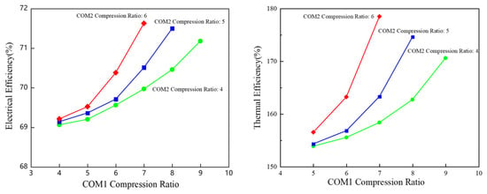
Figure 3.
The variation in electrical and thermal efficiencies with COM1 compression ratio when COM2 is held constant.
The relationship between the compression/expansion ratio and the number of stages demonstrates that reducing the number of compression stages leads to a progressive increase in the compression ratio allocated to each stage, as shown in Figure 4. This effect becomes significantly more pronounced as the number of stages decreases, resulting in a non-linear amplification of the per-stage compression ratio. The thermodynamic load on individual stages intensifies accordingly, necessitating careful consideration of mechanical and thermal constraints in system design.
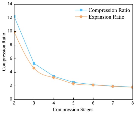
Figure 4.
Variation in Compression/Expansion Ratio with the Number of Stages.
4.2. Analysis of the Impact of Air Outlet Temperature on System Performance
Thermodynamic studies of compressed air energy storage systems indicate that the temperature rise during air compression significantly impacts overall system performance. Excessive compression temperatures not only compromise equipment reliability but also diminish system efficiency. Therefore, system design must prioritize the control of cooling temperatures for compressed air. Theoretical analyses demonstrate that maintaining the cooling temperature of compressed air within an optimal range establishes a positive correlation between system performance and outlet temperature, primarily due to the enhanced energy quality achieved through optimized thermal management [].
Furthermore, the study reveals that the setting of the compression ratio significantly influences the operational conditions of each compressor stage. As the compression ratio increases, both the outlet temperature and pressure rise correspondingly across all compressor stages, imposing more stringent design requirements. This necessitates improved performance from heat exchange equipment and greater temperature and pressure resistance from critical components. In practical engineering applications, identifying the optimal balance between temperature and pressure parameters and system efficiency becomes crucial, providing essential guidance for the optimized design of compressed air energy storage systems.
As illustrated in Figure 5, an increase in the compressor outlet temperature from 150 degrees Celsius to 190 degrees Celsius leads to a 22.5 percent reduction in electrical efficiency, primarily due to elevated heat dissipation losses. Using a three-stage compression system as an example, the right table presents stage-specific conditions: the outlet temperature of the first stage reaches 195 degrees Celsius at 26 megapascals, the second stage at 254 degrees Celsius and 33 megapascals, and the third stage at 284 degrees Celsius and 38 megapascals. These operating parameters necessitate final-stage piping capable of withstanding temperatures approaching 300 degrees Celsius while ensuring adequate safety margins.
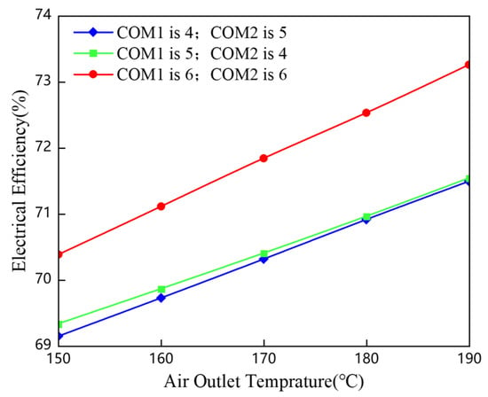
Figure 5.
Variation in electrical efficiency with increasing air outlet temperature.
The analysis further highlights critical transient thermal behavior, with pipe wall temperatures fluctuating at rates of 25 degrees Celsius per minute during transitions between charge and discharge modes. These rapid temperature changes create conditions conducive to thermal stress crack formation.
4.3. Analysis of the Impact of Compression/Expansion Stage Configuration on System Performance
The design of stage configuration requires a careful balance between efficiency and cost considerations. When determining the number of compression stages, two key factors must be weighed: reducing the number of stages to minimize interstage piping and heat exchangers, thereby decreasing pressure losses and heat dissipation, and allocating higher compression ratios to lower-pressure stages, which results in elevated outlet temperatures.
Given the complexity of thermal storage systems, it is advisable to implement a maximum of two to three distinct high-temperature storage levels. In any single storage tank, the temperature reflects a blended average of the thermal media from different heat exchangers []. To preserve high-grade thermal energy, it is essential to maintain similar or identical temperatures across various heat exchangers, necessitating comparable or uniform outlet temperatures from all compressor stages.
In the compression-expansion system model developed for this study, as shown in Figure 6, the stage count was varied between 2 and 4. Modifications to either compression or expansion stages demonstrated measurable impacts on both electrical and thermal efficiency. Figure 6 reveals distinct trends when maintaining 3 compression stages while increasing expansion stages from 2 to 4: electrical efficiency initially rises and then declines, while thermal efficiency shows gradual but decelerating improvement.
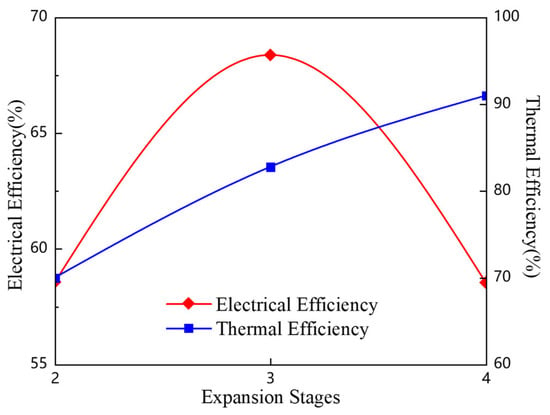
Figure 6.
Variation in air outlet temperature and pressure across compressor stages in the system process.
The initial efficiency improvement is attributed to more complete pressure release achieved through additional expansion stages, which reduces throttling losses. With only 2 expansion stages, the excessive pressure ratio in single-stage expansion creates supersonic flow velocities that generate shock waves, converting kinetic energy into frictional heat dissipation. By implementing 3 expansion stages, subsonic flow is maintained throughout, boosting mechanical energy conversion efficiency from 55% to 70%.
However, increasing the number of stages further introduces diminishing returns. Each additional stage beyond 3 adds approximately 2% mechanical loss due to bearing and seal friction, while the 40% longer flow path increases pressure drop by 1.5 MPa. These compounded losses ultimately reduce electrical efficiency from 70% back to 65%, highlighting the existence of an optimal stage configuration.
4.4. Exergy Loss Analysis in Compression Energy Storage/Expansion Power Generation Processes
This study employs a systematic exergy analysis approach, establishing a comprehensive framework for evaluating exergy destruction through three key analytical models: the actual operational cycle, the ideal optimal cycle, and the hybrid cycle. The methodology begins by distinguishing between avoidable and unavoidable exergy losses in system operation by comparing the actual operational cycle with the ideal optimal cycle. It then accurately identifies the distribution characteristics of endogenous and exogenous exergy destruction through analysis of the actual operational cycle versus the hybrid cycle. Finally, the approach quantifies the unavoidable endogenous exergy destruction component by comparing the ideal optimal cycle with the hybrid cycle.
Figure 7 illustrates the computational methodology for advanced exergy analysis. The superscripts “real,” “optimal,” and “hybrid” in the figure denote the actual cycle, the optimal cycle, and the hybrid cycle, respectively. As shown, by comparing the actual thermodynamic cycle with the optimal thermodynamic cycle, the avoidable and unavoidable exergy destruction can be determined. Similarly, comparing the actual thermodynamic cycle with the hybrid thermodynamic cycle allows for the calculation of endogenous and exogenous exergy destruction. Furthermore, analyzing the optimal cycle and the hybrid cycle enables the quantification of the unavoidable endogenous exergy destruction, thereby facilitating the comprehensive evaluation of all categories of exergy destruction.
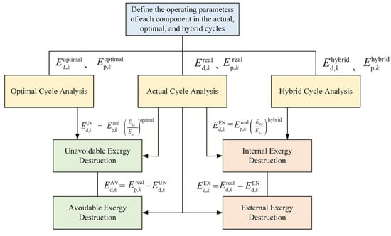
Figure 7.
Advanced exergy analysis methodology.
The exergy analysis results derived from the system’s actual operational cycle, as illustrated in the accompanying figure, clearly reveal the distribution and relative contribution of exergy losses across major components during a complete operational cycle. The analysis demonstrates that compressors and expansion turbines-being the core energy conversion devices-exhibit significantly higher exergy destruction compared to other components []. This is primarily attributable to three factors: first, inherent mechanical losses in rotating machinery, including bearing friction and seal leakage, represent unavoidable dissipation; second, substantial enthalpy changes between inlet and outlet streams amplify exergy destruction during energy conversion; third, off-design operational conditions further exacerbate efficiency degradation and consequent exergy losses.
Figure 8 illustrates the exergy destruction of major components during one operational cycle and their respective contributions to the total system exergy loss. The analysis reveals significantly higher exergy destruction in compressors and expansion turbines, primarily due to their essential roles as the main work-energy conversion devices. The exergy analysis reveals that compressors and turbines collectively account for approximately 65% of the total exergy destruction, as quantitatively illustrated in Figure 6. This prominence stems from their inherent mechanical limitations and thermodynamic constraints. These components inherently exhibit substantial mechanical losses, which are further compounded by the considerable enthalpy differentials between their inlet and outlet working fluids, resulting in pronounced exergy destruction. Among the heat exchangers, the oil-gas heat exchanger demonstrates significantly greater exergy destruction compared to the gas-water heat exchanger, owing to its critical function as the central thermal energy transfer unit in the system.
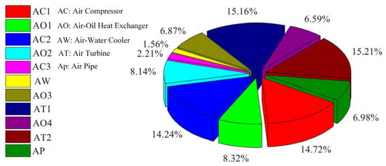
Figure 8.
Exergy destruction distribution in actual cycle components.
As illustrated in Figure 8, exergy analysis reveals that compressors and turbines are the dominant sources of loss, collectively accounting for approximately 65% of the total exergy destruction. This prominence is attributed to three primary factors: First, inherent mechanical dissipations such as bearing friction and seal leakage in this rotating machinery. Second, the substantial enthalpy changes they handle significantly amplify the intrinsic thermodynamic irreversibility. Third, operational deviations from design conditions further exacerbate efficiency degradation. Consequently, targeting these core components for improvement-through advanced aerodynamic designs, adaptive control strategies, and innovative sealing technologies-represents the most effective pathway to enhance overall system performance.
The concentration of exergy losses in these critical components fundamentally governs the system’s overall energy conversion efficiency. This understanding highlights the necessity of prioritizing technological improvements in these areas, including advanced aerodynamic designs to optimize flow paths, adaptive control strategies to maintain performance under varying conditions, and innovative sealing technologies to minimize mechanical losses. Addressing these core issues represents the most effective pathway toward enhancing the system’s overall exergy efficiency and operational performance.
5. Conclusions
In conclusion, the compressed air energy storage system utilizes both constant-pressure and variable-pressure control modes. While the variable-pressure mode significantly enhances system efficiency through dynamic adjustments of compression and expansion ratios, it necessitates more sophisticated control systems. This study, employing a three-stage compression/expansion system and the control variable method, demonstrates that with a fixed secondary compression ratio, the system’s electrical and thermal efficiency improves as the primary compression ratio increases. These findings provide critical insights for system optimization, although practical applications must carefully balance efficiency gains against additional investment costs.
The compression/expansion ratio, air outlet temperature, and number of compression/expansion stages are key parameters affecting system performance. Studies show that adopting a variable-pressure operation mode can improve system efficiency compared to constant-pressure mode, with each unit increase in the compression ratio enhancing round-trip efficiency by approximately 1.8%. Optimizing the inter-stage cooling temperature to 150 °C effectively reduces thermal losses, resulting in a 22.5% reduction in system exergy destruction. Thermodynamic analysis reveals that the temperature rise during compression directly impacts both performance and reliability. Effective cooling temperature control can enhance system efficiency, while increased compression ratios elevate outlet temperatures and pressures across all stages. This necessitates optimized heat exchangers and enhanced material resistance, establishing fundamental guidelines for system parameter optimization.
Thermal efficiency increases monotonically with additional expansion stages, whereas electrical efficiency peaks at three stages (approximately 70%) before declining due to increased parasitic losses. This indicates the need to balance thermal and electrical efficiency. Reducing the number of compression stages simplifies the system and lowers costs but results in higher single-stage compression ratios and outlet temperatures, necessitating a comprehensive consideration of equipment temperature and pressure resistance capabilities along with overall system efficiency.
Stage optimization in compressed air energy storage systems requires a balance between system simplicity and thermodynamic performance. Studies indicate that while reducing the number of compression stages lowers complexity, it necessitates careful temperature management in low-pressure segments. A thermal storage system designed with 2 to 3 distinct temperature zones effectively balances efficiency and practicality. In the 2–4-stage system model, thermal efficiency increases monotonically with the number of expansion stages, whereas electrical efficiency exhibits a rise-and-fall pattern consistent with expansion power trends. Notably, although fewer compression stages improve heat utilization, they also raise final-stage exhaust temperatures—a critical consideration for stage configuration design. The implementation of a multi-stage compression system with inter-stage cooling, combined with multi-stage expansion and inter-stage reheating, along with a multi-temperature zone thermal storage system, enables cascade utilization of thermal energy, thereby enhancing overall system efficiency and operational flexibility. Maintaining similar outlet temperatures across all compressor stages helps minimize high-grade thermal energy losses, optimizing both thermal storage performance and overall system efficiency.
Overall, the study reveals several previously unreported optimization laws—including a monotonic pressure-ratio-efficiency coupling mechanism, an optimal 150–160 °C inter-stage temperature window, and a three-stage expansion optimum—supported by advanced exergy decomposition and dual-platform simulation. These findings provide new theoretical and methodological contributions to the design and operation of high-capacity A-CAES systems.
Author Contributions
Conceptualization, Y.Z. (Yuhang Zuo); Methodology, Y.Z. (Yuhang Zuo) and B.L.; Software, B.F.; Validation, B.L.; Writing—original draft, Y.Z. (Yuhang Zuo) and B.L.; Writing—review and editing, B.F., Y.Z. (Yingxia Zheng) and J.L.; Visualization, Y.Z. (Yingxia Zheng); Supervision, J.L.; Project administration, J.L.; Funding acquisition, J.L. All authors have read and agreed to the published version of the manuscript.
Funding
This research received no external funding.
Data Availability Statement
The data presented in this study are available on request from the corresponding author. The data are not publicly available due to ongoing research.
Conflicts of Interest
Authors Yuhang Zuo, Biao Feng, and Yingxia Zheng were employed by the company Power China Huadong Engineering Corporation (China). The remaining authors declare that the research was conducted in the absence of any commercial or financial relationships that could be construed as a potential conflict of interest.
References
- Zhang, S.; Wang, D.; Cheng, H.; Song, Y.; Yuan, K.; Du, W. Key technologies and challenges of low-carbon integrated energy system planning for carbon emission peak and carbon neutrality. Autom. Electr. Power Syst. 2022, 46, 189–207. [Google Scholar]
- Rabi, A.M.; Radulovic, J.; Buick, J.M. Comprehensive review of compressed air energy storage (CAES) technologies. Thermo 2023, 3, 104–126. [Google Scholar] [CrossRef]
- Barbour, E.R.; Pottie, D.L.F. Adiabatic Compressed Air Energy Storage Systems; Elsevier: Amsterdam, The Netherlands, 2022. [Google Scholar]
- Zhang, X.; Gao, Z.; Zhou, B.; Guo, H.; Xu, Y.; Ding, Y.; Chen, H. Advanced compressed air energy storage systems: Fundamentals and applications. Engineering 2024, 34, 246–269. [Google Scholar] [CrossRef]
- Liu, H.; Yang, C.; Liu, J.; Hou, Z.; Xie, Y.; Shi, X. An overview of underground energy storage in porous media and development in China. Gas Sci. Eng. 2023, 117, 205079. [Google Scholar] [CrossRef]
- Gasanzade, F.; Bauer, S. Approximating coupled power plant and geostorage simulations for compressed air energy storage in porous media. Appl. Energy 2025, 380, 125070. [Google Scholar] [CrossRef]
- Li, Y.; Teng, S.; Xi, H. 3E analyses of a cogeneration system based on compressed air energy storage system, solar collector and organic Rankine cycle. Case Stud. Therm. Eng. 2023, 42, 102753. [Google Scholar] [CrossRef]
- Yao, E.; Zhong, L.; Li, R.; Zhao, C.; Wu, S.; Wang, H.; Xi, G. Enhanced compression heat recovery of coupling thermochemical conversion to trigenerative compressed air energy storage system: Systematic sensitivity analysis and multi-objective optimization. J. Energy Storage 2023, 68, 107738. [Google Scholar] [CrossRef]
- Zeng, Z.; Ma, H.; Yang, C.; Liao, Y.; Wang, X.; Cai, R.; Fang, J. Effect of the dynamic humid environment in salt caverns on their performance of compressed air energy storage: A modeling study of thermo-moisture-fluid dynamics. Appl. Energy 2025, 377, 124403. [Google Scholar] [CrossRef]
- Migliari, L.; Micheletto, D.; Cocco, D. A hydrogen-fuelled compressed air energy storage system for flexibility reinforcement and variable renewable energy integration in grids with high generation curtailment. Energy Convers. Manag. 2024, 306, 118308. [Google Scholar] [CrossRef]
- Khalafian, F.; Iliaee, N.; Diakina, E.; Parsa, P.; Alhaider, M.M.; Masali, M.H.; Pirouzi, S.; Zhu, M. Capabilities of compressed air energy storage in the economic design of renewable off-grid system to supply electricity and heat costumers and smart charging-based electric vehicles. J. Energy Storage 2024, 78, 109888. [Google Scholar] [CrossRef]
- Jafarizadeh, H.; Soltani, M.; Assad, M.E.H.; Dusseault, M. Optimizing industrial compressed air energy storage performance: A novel exergoeconomic framework via pressure-temperature dependent cost analysis. Energy 2025, 323, 135716. [Google Scholar] [CrossRef]
- Adib, M.; Nasiri, F.; Haghighat, F.; Panchabikesan, K.; Venkataramani, G.; Tiwari, S.; Ramalingam, V. Integrating compressed air energy storage with wind energy system—A review. E-Prime-Adv. Electr. Eng. Electron. Energy 2023, 5, 100194. [Google Scholar] [CrossRef]
- Adib, M.; Nasiri, F.; Haghighat, F. Integrating wind energy and compressed air energy storage for remote communities: A bi-level programming approach. J. Energy Storage 2023, 72, 108496. [Google Scholar] [CrossRef]
- Xue, X.; Li, S.; Shi, T.; Xu, G.; Zheng, L.; Chang, S. Performance analysis of a compressed air energy storage incorporated with a biomass power generation system. Appl. Therm. Eng. 2024, 248, 123281. [Google Scholar] [CrossRef]
- Zhang, Y.; Zhang, W.; Li, R.; Wang, H.; He, X.; Li, X.; Du, J.; Zhang, X. Thermodynamic and economic analysis of a novel compressed air energy storage system coupled with solar energy and liquid piston energy storage and release. Energy 2024, 311, 133394. [Google Scholar] [CrossRef]
- Khan, A.; Bradshaw, C.R. Quantitative comparison of the performance of vapor compression cycles with compressor vapor or liquid injection. Int. J. Refrig. 2023, 154, 386–394. [Google Scholar] [CrossRef]
- Jankowski, M.; Pałac, A.; Sornek, K.; Goryl, W.; Żołądek, M.; Homa, M.; Filipowicz, M. Status and development perspectives of the compressed air energy storage (CAES) technologies—A literature review. Energies 2024, 17, 2064. [Google Scholar] [CrossRef]
- Assareh, E.; Hoseinzadeh, S.; Karami, A.; Bazazzadeh, H.; Groppi, D.; Garcia, D.A. The performance analysis of a compressed air energy storage (CAES) for peak moving with cooling, heating, and power production. Case Stud. Therm. Eng. 2024, 64, 105448. [Google Scholar] [CrossRef]
- Tayyeban, E.; Deymi-Dashtebayaz, M.; Farzaneh-Gord, M. Multi-objective optimization for reciprocating expansion engine used in compressed air energy storage (CAES) systems. Energy 2024, 288, 129869. [Google Scholar] [CrossRef]
- Wei, L.; Liu, X.; Wu, F.; Li, H.; Wu, Y.; Zhou, H. Performance analysis of a novel isobaric compressed air energy storage (CAES) system based on dual fluid. J. Energy Storage 2025, 108, 115001. [Google Scholar] [CrossRef]
Disclaimer/Publisher’s Note: The statements, opinions and data contained in all publications are solely those of the individual author(s) and contributor(s) and not of MDPI and/or the editor(s). MDPI and/or the editor(s) disclaim responsibility for any injury to people or property resulting from any ideas, methods, instructions or products referred to in the content. |
© 2025 by the authors. Licensee MDPI, Basel, Switzerland. This article is an open access article distributed under the terms and conditions of the Creative Commons Attribution (CC BY) license (https://creativecommons.org/licenses/by/4.0/).