Article

Exploring the Potential of R744 as a Sustainable Refrigerant for Marine Applications: A Comparative Performance Analysis with Current Refrigeration Framework

by
Martina D’Onofrio
*,
Fabio Petruzziello
,
Arcangelo Grilletto
,
Ciro Aprea
and
Angelo Maiorino
Department of Industrial Engineering, Università di Salerno, Via Giovanni Paolo II, 132, 84084 Fisciano, Salerno, Italy
*
Author to whom correspondence should be addressed.
Energies 2025, 18(23), 6211; https://doi.org/10.3390/en18236211 (registering DOI)
Submission received: 16 October 2025 / Revised: 18 November 2025 / Accepted: 25 November 2025 / Published: 27 November 2025

Abstract

In the naval sector, hydrofluorocarbons (HFCs) are the primary refrigerants in use. To face global environmental challenges, international treaties have established stringent regulations aimed at transitioning towards more sustainable alternatives. Natural refrigerants are proposed as valid solutions, with a particular focus on carbon dioxide (R744) due to its very low direct environmental impact and high safety. This paper evaluates the potential of using R744 as a refrigerant for refrigeration systems onboard cruise ships; based on the R744 innovative solutions currently proposed in the literature for cruise ship applications, the aim is to assess whether the transition to R744 would provide advantages in terms of energy performance and total environmental impact compared with conventional systems employing HFCs. The analysis includes a description of the conventional provision and air conditioning systems mounted onboard and innovative technologies utilizing R744 as a refrigerant, proposed in the literature. These systems are numerically analyzed and compared. The numerical results show that the exclusive use of R744 in onboard systems would significantly reduce the direct environmental impact compared with the current HFCs-based configurations. However, when considering the total impact, further technological advancements in R744 systems are required to achieve a reduction in indirect emissions as well. While progressing toward full R744 adoption, some promising pathways are proposed to enhance current system efficiency.

1. Introduction

Nowadays, the maritime sector contributes significantly to GHG emissions. Generally, the onboard demanded electricity is produced by engines powered by fossil fuels, and with respect to this total produced energy, heating, ventilation, air conditioning and refrigeration (HVAC&R) systems account for an average of about 40% on cruise ships [1], between 51.5% and 70% on merchant vessels [2], around 50% on fishing vessels [3], and between 18% and 57% on military ships [4]. In 2012, carbon dioxide (CO2) emissions relating to fuel consumption in the maritime sector amounted to 962 million tonnes, and in 2018 an increase of 9.8% was recorded, corresponding to 2.89% of global anthropogenic emissions [5]. From a prediction of future CO2 emissions, by assuming 2008 as the reference year, it is estimated that GHG emissions will increase from 90%, achieved in 2018, up to 130% in 2050. This increase is driven by expected growth in global maritime trade and transportation demand [6].
However, another source of emissions is related to vibrations during sea transport that damage pipelines, causing particularly high refrigerant leakage rates [7]. The high GWP refrigerant leaks from HVAC&R systems onboard increased by 15.9%, from 15.7 million tonnes of CO2 equivalent in 2012 to 18.2 million tonnes of CO2 equivalent in 2018 [5].
Currently, no specific restrictions on refrigerant use are enforced in the maritime sector. However, given the international nature of shipping, this sector is receiving increasing attention in the pursuit of effective decarbonization strategies aimed at limiting the inevitable rise in emissions.
International treaties related to refrigeration establish low-GWP refrigerants as the only substances allowed for future use. Within this regulatory framework, the Kigali Amendment to the Montreal Protocol lays the foundation for the global phase-down of HFCs over the coming decades, with the objective of limiting global warming by up to 0.5 °C by the end of the century. To achieve this target, approximately 80% of HFCs consumption must be phased out before 2050 [8].
The EU Regulation on F-gases 2024/573 ensures long-term compliance with its international obligations under the Kigali Amendment, particularly regarding the progressive reduction in HFCs’ production and consumption. This includes a gradual phase-down of production and additional measures to limit the placing of HFCs with the GWP above 150 on the market after 2030. By 1 January 2030, the European Commission shall publish a report assessing the impact of this Regulation, which will also consider the potential extension of containment requirements to HFCs used in refrigeration and air conditioning equipment onboard ships [9].
Natural refrigerants and hydrofluoroolefines (HFOs) represent the most promising options currently available to substitute HFCs, as they exhibit zero ozone depletion potential and a GWP lower than 150 [10,11,12]. In addition to environmental criteria, safety-related aspects, i.e., toxicity and flammability, must also be considered when selecting a refrigerant, according to the classification established by the American Society of Heating, Refrigerating and Air-Conditioning Engineers (ASHRAE) standards [13]. Hydrocarbons, like propane (R290, GWP = 3), are classified as A3 due to their high flammability and for this reason can be safely used only within compact systems operating with low refrigerant charges. Ammonia (R717, GWP = 0) offers advantages in terms of flammability resistance but is classified as B2L, indicating high toxicity. HFOs, like R1234yf (GWP = 4), fall within the same flammability class as ammonia but are classified as A2L because they are non-toxic and odourless, thus avoiding the risk of panic among crew members in the event of leaks. However, a critical concern associated with HFOs is the formation of trifluoroacetic acid (TFA) as a degradation product in the atmosphere. TFA is a persistent pollutant and harmful when inhaled. Therefore, considering safety and environmental aspects together, the most suitable choice is R744 (GWP = 1), a non-flammable and non-toxic working fluid with a safety class of A1. It is increasingly recognized as one of the most promising refrigerants for shipboard applications [12,14,15]. It should be noted that at concentration levels above 10%, R744 may have toxic effects. Consequently, especially in confined or small spaces, CO2 concentrations must be carefully monitored in the event of possible leaks [16].
However, the typical operating conditions of marine refrigeration plants often result in the occurrence of transcritical cycles. They are characterized by higher thermodynamic losses compared to conventional refrigeration cycles [14]. For this reason, there is a considerable interest in adopting innovative technologies, designed to specifically operate efficiently with R744. Indeed, several thermodynamic cycle and hardware modifications have been proposed, such as those with internal heat exchangers [17,18,19], subcooling methods [20,21], ejector/multi-ejectors [22,23] and parallel compression cycles [24,25].
The intent of this paper is to introduce a new perspective by analyzing the challenges of adopting R744-based innovative technologies for marine refrigeration systems, proposed in the literature, in comparison with HFCs-based conventional solutions. This approach represents a significant element of novelty, as existing studies typically evaluate R744-based alternatives in isolation, without benchmarking them against current systems. Assessing true sustainability and the potential contribution to decarbonization necessarily requires a comparative evaluation with the configurations presently in use.
This focus is placed on cruise ships due to their higher fuel consumption and emission levels per unit compared to other types of vessels. The average annual fuel consumption for a cruise ship between 2012 and 2018 was just under 15 kt of Heavy Fuel Oil-equivalent, the highest among all vessel types on international voyages [5]. Therefore, in order to achieve sustainable tourism, it is necessary to investigate refrigeration and air conditioning systems that are as energy-efficient as possible.
In this study, the analysis specifically focuses on the refrigeration branches of HVAC&R systems installed onboard cruise ships, i.e., provision systems for food preservation and air conditioning systems ensuring passenger and crew comfort. Hence, throughout the paper, the acronym HVAC&R will refer to these systems.
Conventional refrigeration systems architectures are reviewed and theoretical plant configurations with R744 are examined. Then, they are compared to determine the effect of transitioning to R744 on system energy performance and total environmental impact.

2. Conventional and Innovative Systems: Description and Numerical Approach

This section describes conventional and innovative systems, focusing on their operating principles, thermodynamic processes, relevant equations and iterative methods for a numerical approach.
The energy and environmental analysis of these systems is based on steady-state energy balance equations applied to each component of the systems.
Conventionally, the HVAC&R systems onboard utilize sea water as a heat sink [12,26,27,28]. Summer conditions are considered in the modelling phase by adopting monthly averages for sea water worldwide [29,30]. Particularly, the two boundary values considered, 16.0 °C and 35.0 °C, correspond to extreme summer conditions documented, e.g., in northern European cruise regions like Stockholm and in the Persian Gulf along the coast of Qatar. Intermediate values of 23.0 °C and 30.0 °C were also selected as representative of typical summer operating conditions encountered, e.g., in the Mediterranean and in tropical waters. Therefore, the chosen set of temperatures spans the realistic range of heat sink conditions a cruise ship may encounter during its global operations.
Simulations are implemented using MATLAB R2024a, and the refrigerant thermodynamic properties are evaluated using REFPROP 10.0 [31].
Energy equations are solved to determine the COP of the plants. The adopted thermodynamic modelling approach is as follows: operating conditions are first derived from literature sources, selecting the values most representative of each configuration and refrigerant, so as to maintain a realistic framework despite the theoretical nature of the analysis. Some operating conditions are kept identical, for instance, the evaporation temperatures in the provision and air conditioning systems, since they are defined by the user side. For those parameters without direct correspondence in the literature, variable ranges are assumed. Therefore, for each sea water temperature considered, the combination of parameters providing the maximum COP is identified, and this optimization is performed independently for each configuration and for each working fluid. This procedure is applied across all system configurations, ensuring a comparative analysis based on COP-optimal operating conditions.
Additionally, an environmental analysis is based on the TEWI [kgCO2], defined through Equation (1) [32], while Equations (2) and (3) allow the calculation of direct, CO2,dir [kgCO2], and indirect contributions, CO2,indir [kgCO2]:
T E W I = C O 2 , d i r + C O 2 , i n d i r  
C O 2 , d i r = R C · P L + 1 P R V · V · G W P
C O 2 , i n d i r = α · Q r e f ˙ C O P · H · V
This paper refers to a medium-sized cruise ship, 177 m long and 28 m wide. The provision system is characterized by a cooling load of 90 kW and a freezing demand of 22 kW [28]. The air conditioning cooling load of 3.0 MW is estimated based on the same reference source, taking into account the reported cooling demand values at sea water temperatures of 16 °C, 23 °C, and 30 °C. The corresponding value at 35 °C is obtained by interpolation with respect to temperatures. Since the resulting range of cooling capacities spans from 1.1 MW to 4.7 MW, an averaged value of 3.0 MW is adopted as a representative reference load for the simulations.
Refrigerant charges are assumed to be 100 kg for the provision system and 1500 kg for the air conditioning plant. These values refer to conventional shipboard installations operating with HFCs, specifically R404A for the provision system and R134a for the air conditioning plant, which are also the reference configurations considered in this study. The adopted values are derived by scaling literature data [7] according to the cooling loads considered in this paper. For the R744-based circuits, the actual refrigerant charge would likely differ, as the system layout and operating characteristics are different. In particular, R744 operates at significantly higher pressures, which typically requires more robust and heavier components. However, this does not necessarily imply a larger charge for the same cooling capacity; indeed, a smaller charge may be sufficient due to its higher volumetric cooling capacity. Nevertheless, in the absence of specific data for R744-based configurations analyzed in this study, the same charge values as for the conventional HFCs-based systems are assumed as a preliminary approximation. As it will be shown in the results, this assumption proved to be non-influential for R744-based systems, since, from an environmental perspective, the contribution of direct emissions, which depend on the refrigerant charge, represents only a very small fraction of the total TEWI, to the extent that it can be reasonably neglected [33]. Indirect emissions associated with energy consumption dominate the overall environmental impact; therefore, the refrigerant charge exerts only a limited influence on the total impact for the R744 configurations considered in this analysis. A similar assumption is also adopted in previous comparative studies evaluating the transition to low-GWP refrigerants for marine refrigeration plants, where identical refrigerant charges are considered across different working fluids [26].
The following assumptions, all derived from [26], are adopted: annual accidental refrigerant losses of 10%, a refrigerant recycling rate of 90%, an expected useful life of the refrigeration system of approximately 30 years, continuous operation throughout the year, and an indirect emission factor of 0.8 kgCO2/kWhe, corresponding to the amount of CO2 emitted per unit of electrical energy required to power the refrigeration system.
In the calculation of indirect CO2 emissions, for each sea water temperature, the corresponding maximum COP value is used.
Since the COP is calculated as the ratio between the cooling capacity and the mechanical power input to the compressor, whereas the indirect emission factor is defined with respect to the electrical power supplied to the refrigeration installation, it is necessary to account for the conversion efficiency, ηem, between the electrical power delivered to the compressor motor and the mechanical power required by the compressor. These efficiencies are reported for the different compressor types in the following subsections dedicated to the description of the circuits.
For HFCs and subcritical R744 cycles, the condensation temperature is set by considering that it typically exceeds the sea water temperature by 6.0–8.0 °C [34], with a representative average difference of 7.0 °C adopted in this work. In the case of transcritical cycles, an approach temperature of 2.0 °C is considered between the refrigerant at the gas cooler outlet and the sea water, since advanced counter-flow gas coolers can operate with a narrow temperature approach, owing to the gliding temperature profile during heat rejection, unlike condensers where larger temperature differences are needed [12]. Compressors and expansion devices are modelled as adiabatic. Pressure drops in heat exchangers and piping and the power required by auxiliary pumps are neglected. These latter assumptions are commonly adopted in similar analyses in the literature, focused on preliminary thermodynamic evaluations [26,27,35].
The following subsection describes the provision and air conditioning layouts analyzed numerically, aiming to provide a comparative thermodynamic assessment of the different configurations. For each component, the thermodynamic processes relevant to the overall system performance are considered, without reference to specific commercial products.
The symbols and the thermodynamic properties appearing in the following subsections are defined in the nomenclature, abbreviations and subscripts sections of this paper.

2.1. Conventional Provision System

A simplified scheme of a conventional provision system (CPS) layout for the cruise ship is represented in Figure 1, based on details obtained from [36].
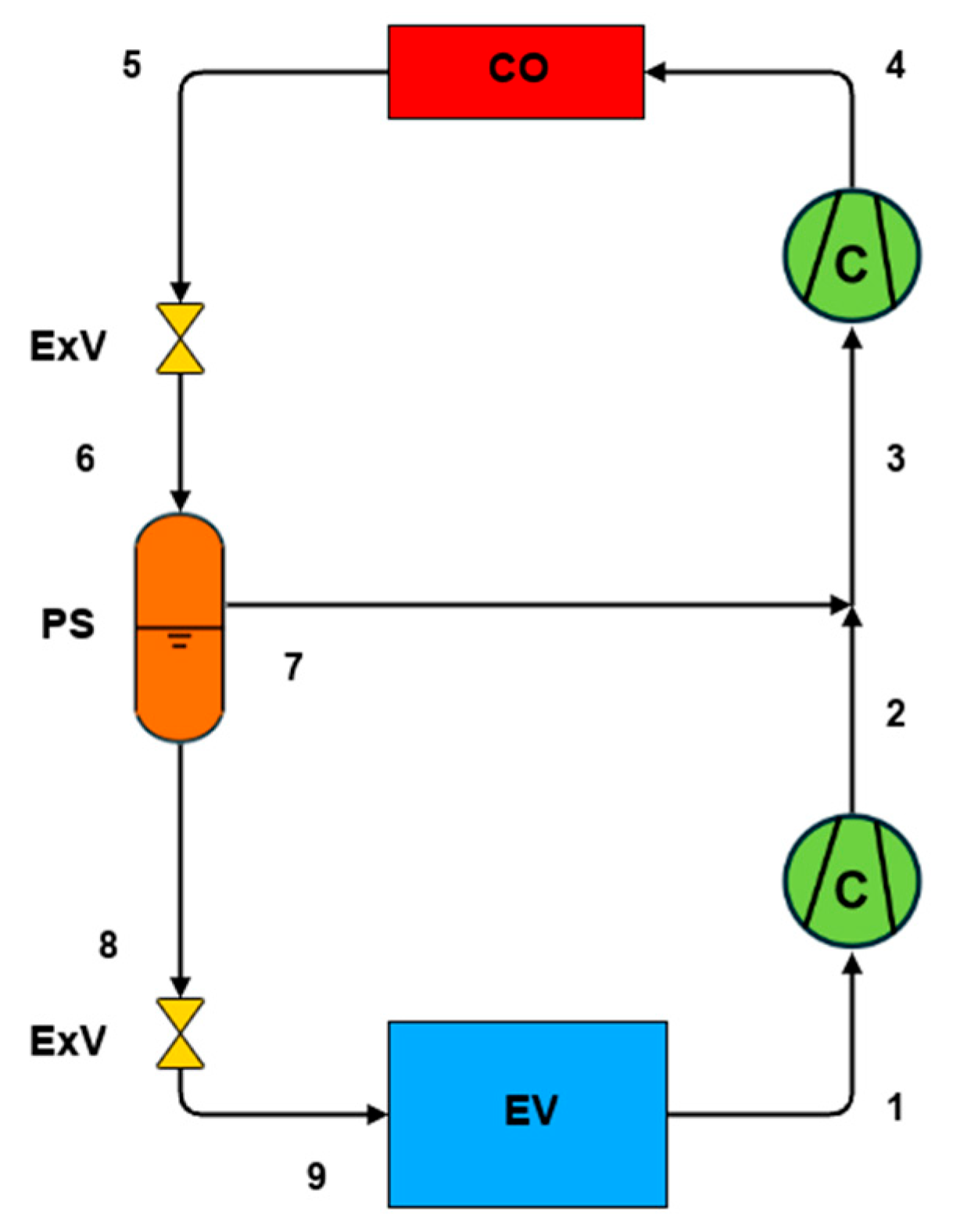
The system is designed with two independent compressor–condenser units that operate alternately to supply the evaporators inside storage rooms. An internal heat exchanger is used to subcool the fluid exiting from the condenser by transferring heat to the fluid coming from the cooling and freezing evaporators. At the outlet of the cooling evaporator, the refrigerant undergoes an additional expansion to the minimum circuit pressure, allowing the mass flow rate from the two branches to rejoin. The subsequent mixing process is assumed to be adiabatic.
In order to perform the numerical analysis, the evaporation temperatures considered are −4.0 °C for cooling and −30.0 ׄ°C for freezing. To model the CPS, the widely used refrigerant R404A is selected [12] and the installation of a screw compressor is assumed for the analysis. The compressor isentropic efficiency, ηis, is calculated through Equations (4)–(6) according to the value of the compression ratio [26]:
η i s = 13.44 r c 2 + 80.64 r c 39.96         f o r   r c 1.5 ; 3
η i s = 0.375 r c 2 + 2.25 r c 77.63         f o r   r c 3 ; 7
η i s = 2.50 r c + 92.50         f o r   r c 7 ; 15
To calculate the thermodynamic properties of the fluid at point 10, it is necessary to implement an iterative procedure. After initializing the fluid’s temperature T10 [°C], the relationship expressing the efficiency of the internal heat exchanger, ε, installed in the circuit is applied, assuming zero subcooling at the condenser outlet (Equation (7)).
ε = T 1 T 10 T 3 T 10    
In this iterative procedure, ε is varied within the range [0, 1].
Equation (7) allows us to determine inlet temperature T1 [°C] and, consequently, the specific enthalpy h1 [kJ kg−1]. Then, the specific enthalpy at the outlet of the internal heat exchanger and inlet of the evaporators, h4 [kJ kg−1], is derived by applying the energy balance to the internal heat exchanger as in Equation (8):
h 4 = h 3 h 1 h 10
In this way, it is possible to calculate the cooling and freezing mass flow rate, m c ˙ [kg s−1] and m f ˙ [kg s−1], required to meet the refrigeration demand through Equations (9) and (10), respectively:
m c ˙ = Q ˙ r e f c ( h 7 h 5 )      
m f ˙ = Q ˙ r e f f ( h 9 h 6 )
At the outlets of the two evaporators, the flow rates are mixed, allowing the resulting specific enthalpy, h10 [kJ kg−1], to be calculated, along with a new value for T10 [°C]. The calculations are repeated with this updated temperature value until convergence on the temperature itself is achieved.
Therefore, the COP of the CPS can be evaluated through Equation (11):
C O P = Q ˙ r e f c + Q ˙ r e f f ( m c ˙ + m f ˙ ) · h 2 h 1
For each sea water temperature, the value of the internal heat exchanger efficiency that maximizes the COP is selected.
For the analysis of the environmental impact, it is assumed that ηem = 89% [37,38].

2.2. Conventional Air Conditioning System

The conventional air conditioning system (CACS) considered is based on products provided by a leading supplier in the refrigeration systems industry [39]. This system features a chiller with a two-stage centrifugal compressor. A simplified layout is shown in Figure 2, developed from the description provided in [39].
In this configuration, the two-stage centrifugal compressor is represented by two compressors arranged in series, in order to clearly illustrate the thermodynamic processes occurring between the first and the second stage. The refrigerant exiting the condenser undergoes an initial expansion to an intermediate pressure before entering a phase separator. From there, the vapour fraction is directed to the second stage of the compressor, while the liquid fraction is expanded further before entering the evaporator. The resulting flow is then drawn into the compressor, where it undergoes an initial compression up to the intermediate pressure. At this point, it merges with the vapour fraction from the phase separator, and the total mass flow rate is compressed to the maximum pressure of the cycle.
For the modelling, the evaporation temperature considered is 3.0 °C, as declared by the manufacturer [39]. The superheating of the flow exiting the evaporator is 5.0 °C [40]. The CACS is assumed to operate with R134a since it is the most commonly used refrigerant in this sector [12].
For the centrifugal compressor, data were collected from the literature [41,42] to create a model of the isentropic efficiency, ηis, as a function of the compression ratio, rc, using polynomial regression, as shown in Equations (12) and (13):
η i s = 6.63 r c 2 + 31.65 r c + 52.55         f o r   r c 1.5 ; 2.5
η i s = 3.33 r c + 84.67         f o r   r c 2.5 ; 5  
In the procedure adopted to determine the thermodynamic state properties, the intermediate pressure is varied within a range bounded by the suction pressure of the first stage and the discharge pressure of the second stage, ensuring compatibility with the compression ratio limits implied by the correlations for the isentropic efficiency.
After evaluating the quality of the refrigerant entering the phase separator, Q6, h3 [kJ kg−1] is determined. This enthalpy results from the adiabatic mixing of two contributions: the liquid fraction, which undergoes compression up to an intermediate pressure, with specific enthalpy h2 [kJ kg−1], and the vapour fraction, directly entering the second stage of the compressor, with specific enthalpy h7 [kJ kg−1]. The resulting enthalpy is expressed by Equation (14):
h 3 = 1 Q 6 · h 2 + Q 6 · h 7
Therefore, the COP of the CACS can be calculated by solving Equation (15):
C O P = 1 Q 6 · ( h 1 h 9 ) 1 Q 6 · h 2 h 1 + ( h 4 h 3 )
For each sea water temperature, the intermediate pressure providing the maximum COP is selected.
The environmental impact assessment is carried out under the assumption of ηem = 90% [43,44].

2.3. Innovative Provision System

In the scientific literature, theoretical models of refrigeration and air conditioning systems operating with R744 designed for maritime applications are deduced from solutions already implemented in other sectors, such as supermarket cooling systems [45,46,47,48].
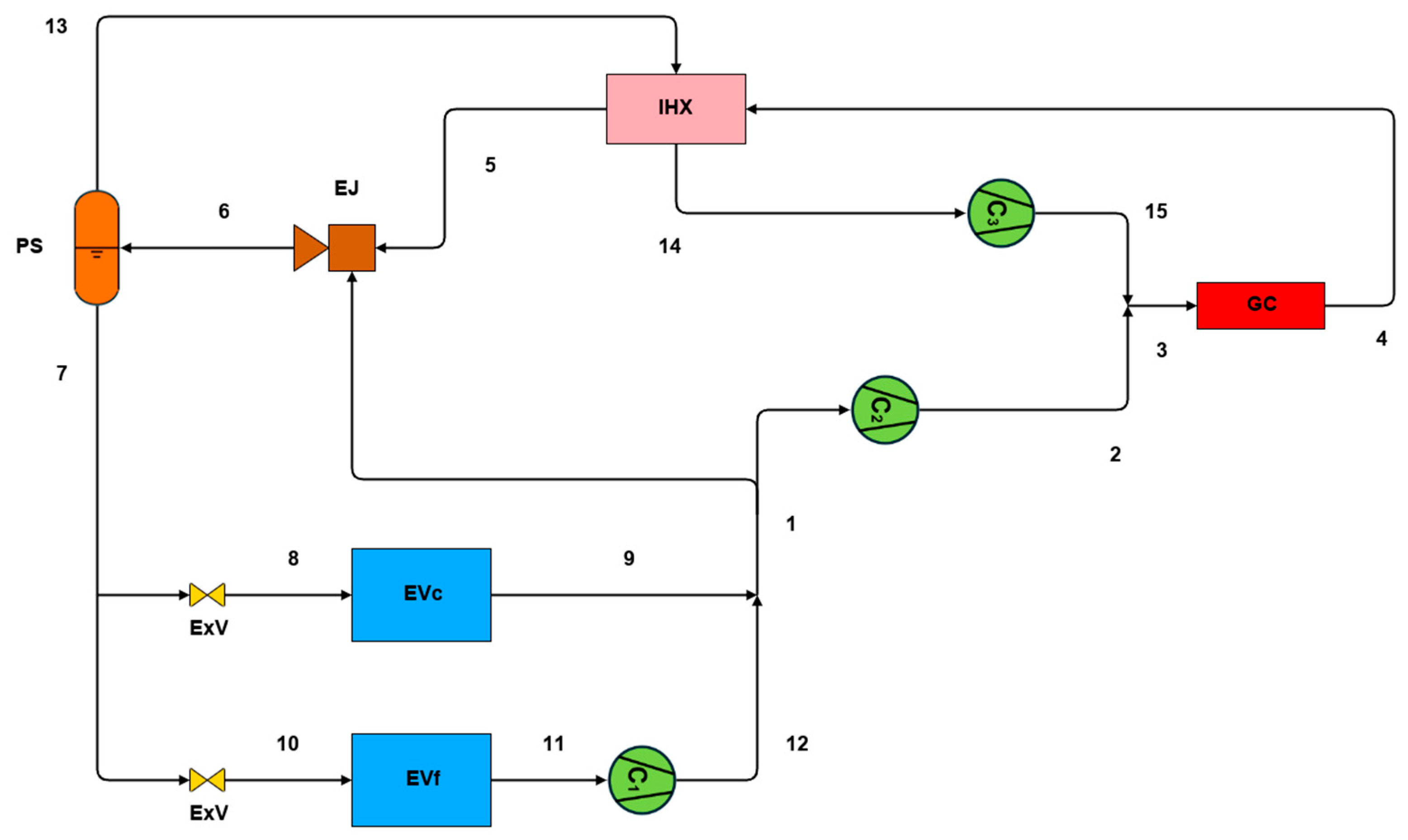
The simplified scheme of a potential model for an innovative provision system (IPS) operating with R744 and designed for implementation on cruise ships is illustrated in Figure 3, based on the scheme outlined in [28].
It incorporates a single gas cooler that transfers thermal energy to sea water. The refrigerant flows through the internal heat exchanger, where it undergoes further cooling before entering the ejector. The ejector conveys refrigerant from the suction line of the medium pressure compressor, C2, and the mixed fluid is discharged into a phase separator. The liquid fraction is supplied to the evaporators for cooling and freezing. The refrigerant from the freezing evaporator enters the low-pressure compressor, C1, before mixing with the refrigerant from the cooling evaporator. Vapour fraction from the phase separator is drawn by the parallel compressor, C3, passing through the internal heat exchanger, and it is compressed to the high side pressure.
For this system, the evaporation temperatures are the same as those of the CPS. Additionally, the superheating downstream of the low-temperature evaporator is 5.0 °C [28]. From the same study, it is assumed that the superheating provided by the intermediate heat exchanger is 5.0 °C, as this value is typically adopted in the scientific literature for layouts integrating both an ejector and an internal heat exchanger [49,50]. Moreover, the intermediate pressure established downstream of the ejector is set to 40 bar, as derived from a reference study analyzing a configuration closely resembling the system investigated here, under comparable operating conditions [49]. Additionally, the ejector efficiency is considered to be 30% since the work recovery efficiency of CO2 ejectors generally lies within the 20–30% range and the overall comparison among all configurations in this study is performed under optimal operating conditions [51].
The installation of reciprocating compressors is assumed. Equations (16) and (17) can be used to calculate the isentropic efficiency, ηis, of the reciprocating compressor as a function of the compression ratio according to the following [26]:
η i s = 15.55 r c 2 + 77.76 r c 24.21         f o r   r c 1.5 ; 2.5
η i s = 4.29 r c + 83.71         f o r   r c 2.5 ; 9    
The mass flow rates through the cooling and freezing evaporators, m c ˙ [kg s−1] and m f ˙ [kg s−1], are determined as expressed by Equations (18) and (19):
m c ˙ = Q ˙ r e f c ( h 9 h 8 )      
m f ˙ = Q ˙ r e f f ( h 11 h 10 )
An iterative procedure is carried out to calculate the fraction of flow x directed to C2 and the vapour mass flow rate m v ˙ extracted from the phase separator and sent to C3. After initializing these two unknowns, the energy balance at the intermediate heat exchanger allows the calculation of h5 and, subsequently, of s5. This enables us to determine the ejector’s entrainment ratio, ϕ , through Equation (20) [52,53,54]:
ϕ = η e j · h 5 h p 6 , s 5 h p 6 , s 1 h 1
By performing the energy balance on the phase separator, the specific enthalpy at the outlet of the ejector flowing into the phase separator, h6 [kJ kg−1] is determined. From the ejector balance, a new value of the vapour mass flow rate, m v ˙ [kg s−1], is derived through Equation (21):
m v ˙ = m l ˙ · h 6 + x · m l · ˙ h 5 + 1 x · m l ˙ h 1 h 6 h 5
With this updated vapour flow rate, the new spill fraction, x′, is calculated based on the definition of the entrainment ratio (Equation (22)):
x = m l ˙ ϕ · m v ˙ m l ˙ · 1 + ϕ
With these updated values for the vapour flow rate and the spill fraction, the previous calculations are repeated until convergence is achieved.
During the calculation process, for transcritical cycles, the maximum pressure is varied within the typical 80–120 bar range [55].
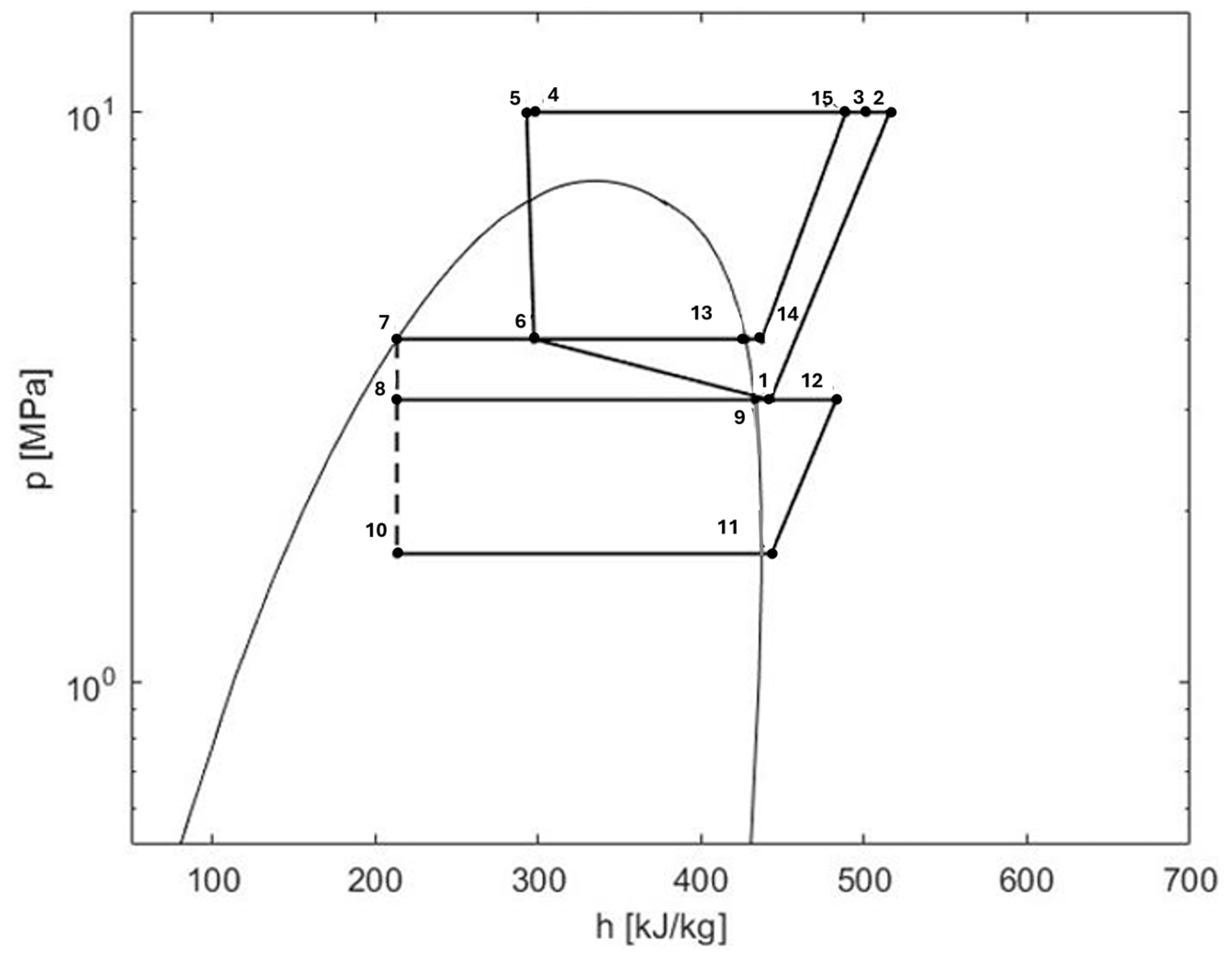
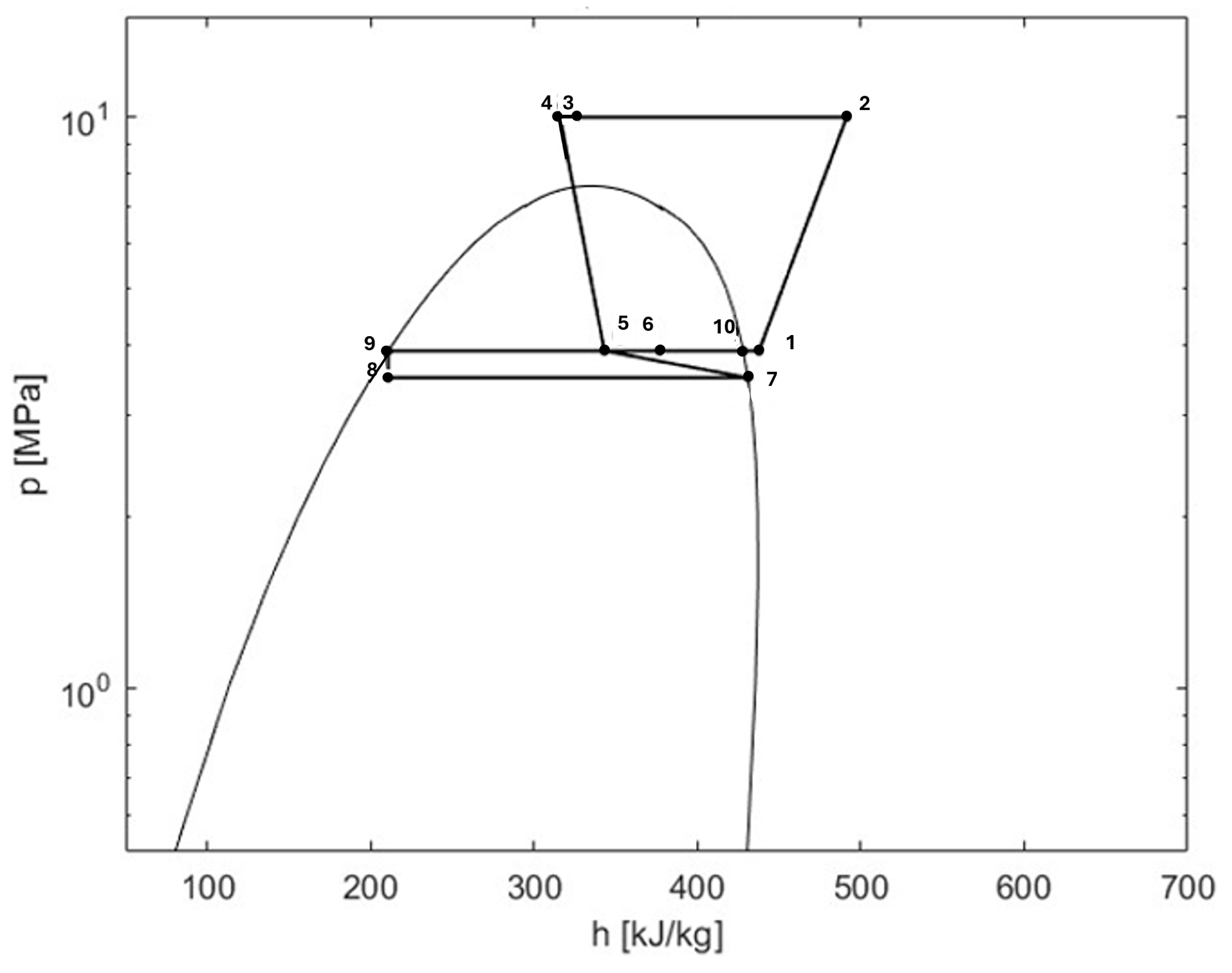
After calculating the thermodynamic properties of the characteristic points of the circuit, the resulting p–h diagram is obtained, as shown in Figure 4 for the transcritical cycle.
The overall COP of the system is defined by Equation (23):
C O P = Q ˙ r e f c + Q ˙ r e f f m c ˙ · h 12 h 11 + x · m c ˙ + m f ˙ · h 2 h 1 + m v ˙ · h 15 h 14
For transcritical operation, the value of the maximum pressure that yields the highest COP is selected for each sea water temperature.
For the evaluation of the environmental impact, ηem = 81% is assumed [56].

2.4. Innovative Air Conditioning System

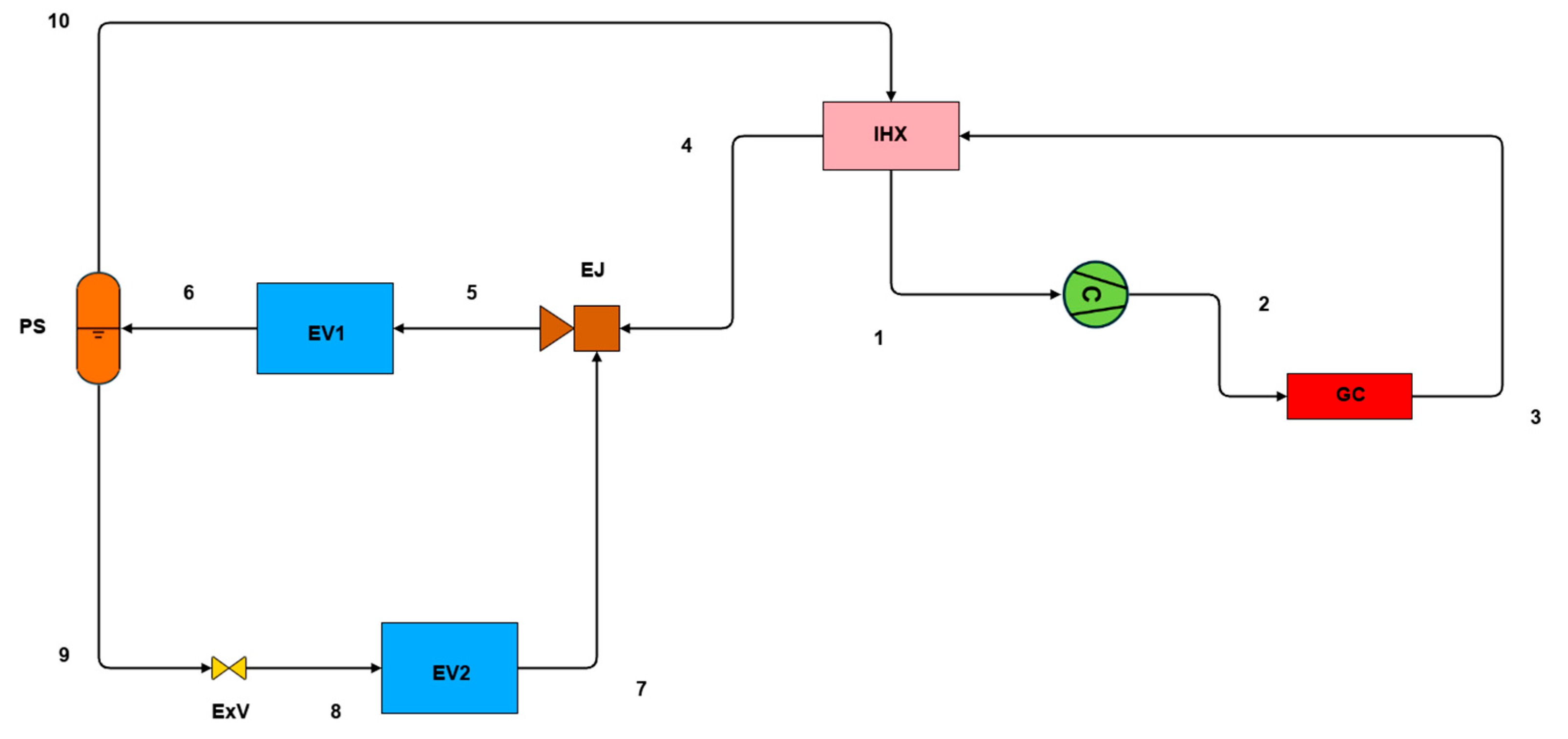
The simplified layout of an innovative air conditioning system (IACS) operating with R744 is shown in Figure 5 adapted from the layout described in [28].
It consists of a single gas cooler that transfers thermal energy to sea water. The refrigerant from the gas cooler flows into an internal heat exchanger, where it is subcooled. The expansion of the high-pressure refrigerant conveys the mass flow rate from the lower-temperature evaporator, EV2. The resulting flow enters the higher-temperature evaporator, EV1, and then is directed to the phase separator. From this component, the liquid refrigerant is throttled through an expansion valve, matching the ejector pressure lift. Next, the refrigerant moves into EV2, where it is conveyed by the ejector. Meanwhile, vapour mass flow rate from the phase separator passes through the internal heat exchanger, where it is superheated before entering the compressor.
For modelling purposes, the operating conditions are defined as follows [57]: 40% of the cooling load, Q ˙ ref,EV 1 , is handled by the cooling evaporator and 60%, Q ˙ ref,EV 2 , by the freezing evaporator. The EV1 pressure is fixed at 39 bar, and the ejector suction flow is considered as saturated vapour. Additionally, the internal heat exchanger provides 5.0 °C superheat at the compressor inlet, and the ejector is modelled with an efficiency of 30%.
To determine the liquid and vapour mass flow rate, m l ˙ [kg s−1] and m v ˙ [kg s−1], an iterative procedure is required. After initializing these two values, the specific enthalpy at the outlet of EV1, h6 [kJ kg−1], is calculated by performing the energy balance on the phase separator, as expressed in Equation (24):
h 6 = ( m v ˙ · h 10 + m l · ˙ h 9 ) m l ˙ + m v ˙
Once h6 is known, the specific enthalpy at the outlet of the ejector, h5 [kJ kg−1], is obtained from the energy balance on the evaporator EV1, Equation (25):
h 5 = m l ˙ + m v ˙ · h 6 Q ˙ r e f , E V 1 m l ˙ + m v ˙
This allows the evaluation of the specific enthalpy at the outlet of EV2, h7 [kJ kg−1], by applying the energy balance on the ejector [53], expressed in Equation (26).
h 7 = m l ˙ + m v ˙ · h 5 m v ˙ · h 4 m l ˙
An additional iteration is necessary to determine the lowest pressure of the circuit, p7 [bar], corresponding to a vapour quality equal to unity for the previously calculated h7. From the expansion valve balance, expressed in Equation (27), it is determined that the specific enthalpy at the inlet of EV2, h9 [kJ kg−1], is the following:
h 8 = h 9
With these results, a new value of the liquid mass flow rate, m l ˙ [kg s−1], is computed, as given in Equation (28), from the balance on the EV2:
m l ˙ = m l ˙ · h 7 Q ˙ r e f E V 2 h 8
Subsequently, the entrainment ratio, ϕ , is evaluated through Equation (29):
ϕ = η e j · h 4 h p 5 , s 4 h p 5 , s 7 h 7
which allows the calculation of the updated value of the vapour mass flow rate, m v ˙ [kg s−1], via Equation (30):
m v ˙ = m l ˙ ϕ
The entire calculation procedure is then repeated with these two updated values of the liquid and vapour fraction until convergence is achieved. During this process, for transcritical cycles, the maximum pressure is varied across the typical 80–120 bar range [55].
Following the evaluation of the thermodynamic properties at the characteristic points of the circuit, the corresponding p–h diagram was derived, as illustrated in Figure 6, for the transcritical cycle.
For the IACS with R744, the COP can be calculated through Equation (31).
C O P = Q ˙ r e f , E V 1 + Q ˙ r e f , E V 2 m v · ˙ h 2 h 1
For transcritical cycles, the value of the maximum pressure that maximizes the COP is selected for each sea water temperature.

2.5. Cascade System

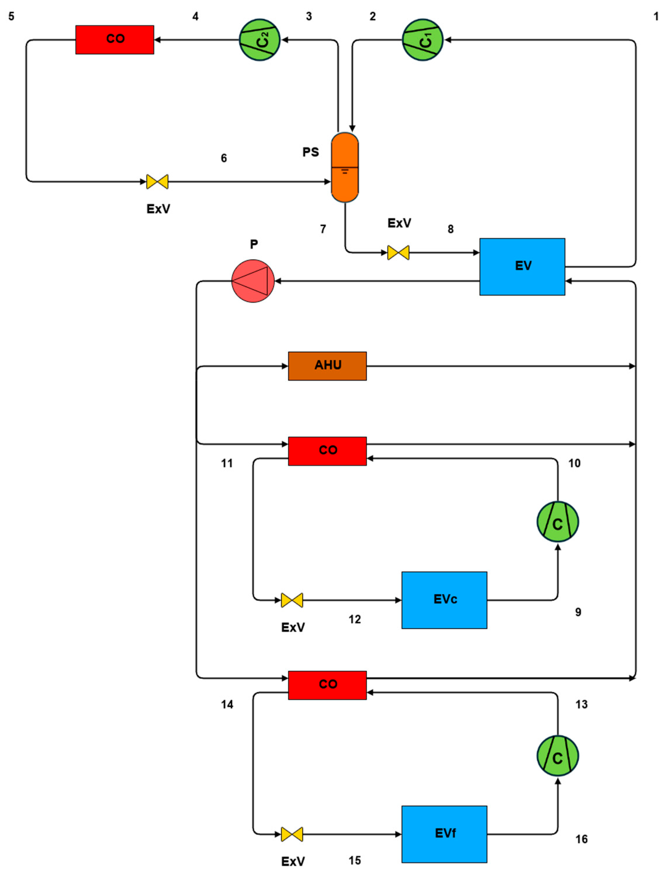
Among the alternative solutions operating with R744 in the scientific literature, the cascade system (CS) is often proposed for cruise ships, integrating an air conditioning plant with cooling and freezing provision systems [12,26]. A simplified plant layout is shown in Figure 7, based on the content presented in [26].
In this CS, the chiller produces chilled water that is partially used to meet air conditioning demand through an air handling unit and partially used to cool the condensers of the cooling and freezing circuits. In the high stage, natural refrigerants or HFOs can be employed to comply with current regulations on GHG emissions. In this second stage, the phase separator cools the superheated vapour, leaving the first centrifugal compressor C1 down to the condition of dry saturated vapour. This vapour, together with the vapour fraction from the fluid exiting the first expansion valve, is then directed to the second centrifugal compressor C2. Meanwhile, the liquid fraction undergoes further expansion before entering the evaporator. In the first stage, a classical vapour compression cycle takes place, operating with R744 which ensures higher system performance. This happens because, in the condensers of the cooling and freezing circuits, the thermal energy is exchanged with chilled water of 7.0 °C [26], allowing the condensation temperature to be under the critical value. From the same reference it is assumed that the temperature difference between condensation temperature and sea water temperature is 7.5 °C, the temperature difference between evaporation temperature of the high-temperature circuit and condensation temperature of the low-temperature circuit is considered 4.5 °C, and the fluid exiting from the evaporator is superheated by 3.0 °C. Additionally, the intermediate pressure, pint [bar], is defined as both centrifugal compressors operate with an equal compression ratio. Consequently, based on Equation (32),
p i n t = p 4 · p 1
The same trend for the isentropic efficiency adopted for the CACS is assumed here.
In this circuit, m c ˙ [kg s−1] is the mass flow rate in the cooling circuit, m f ˙ [kg s−1] is the one in the freezing circuit, and m ˙ HVAC,CO [kg s−1] and m ˙ HVAC,EV [kg s−1] are the ones in the high stage, evolving in the condenser and in the evaporator, respectively. The overall efficiency of the system is calculated by considering the expressions for determining the COP of the cooling, freezing and HVAC systems, respectively, through Equations (33)–(35):
C O P c = Q ˙ r e f c m c ˙ · h 10 h 9
C O P f = Q ˙ r e f f m f ˙ · h 13 h 16
C O P H V A C = Q ˙ r e f a c + Q ˙ r e f c + Q ˙ r e f c C O P c + Q ˙ r e f f + Q ˙ r e f f C O P f m ˙ H V A C , E V · h 2 h 1 + m ˙ H V A C , C O · h 4 h 3

3. Results and Discussion

This section presents a comparison of the illustrated technological solutions by analyzing their efficiency and environmental impact. The analysis is first carried out separately, examining the provision and air conditioning systems individually. A comprehensive evaluation is then presented at the cruise ship level, accounting for the fact that these two systems usually operate simultaneously as part of the integrated HVAC&R plant.

3.1. Provision Systems

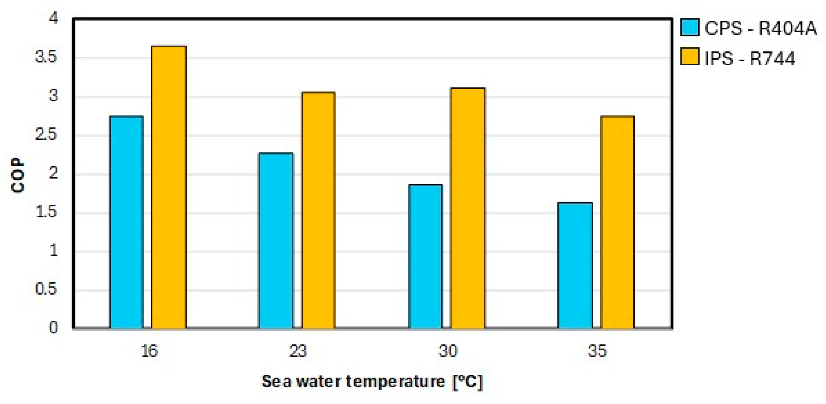
The IPS with R744 introduces significant changes that enhance overall performance compared to the CPS employing R404A. The ejector is proposed to recover part of the energy lost during fluid expansion. Additionally, the phase separator decreases the refrigerant quality entering in the evaporator, resulting in a higher useful refrigeration effect. Another relevant improvement is related to the fact that in the conventional system, the refrigerant leaving the cooling evaporator is further throttled to the minimum cycle pressure. Meanwhile, the innovative system compresses the fluid exiting the freezing evaporator to match the pressure of the fluid in the cooling evaporator. This substitution of the expansion valve with the compressor reduces cycle inefficiencies. As a result, the innovative system exhibits higher performance as can be seen in Figure 8, showing the comparison in terms of COP between the CPS using R404A and the IPS with R744 at different sea water temperatures.
As evident, the COP of the IPS with R744 ranges from approximately 2.7 to over 3.6. Compared to the CPS with R404A, this corresponds to an improvement of 33–69%.
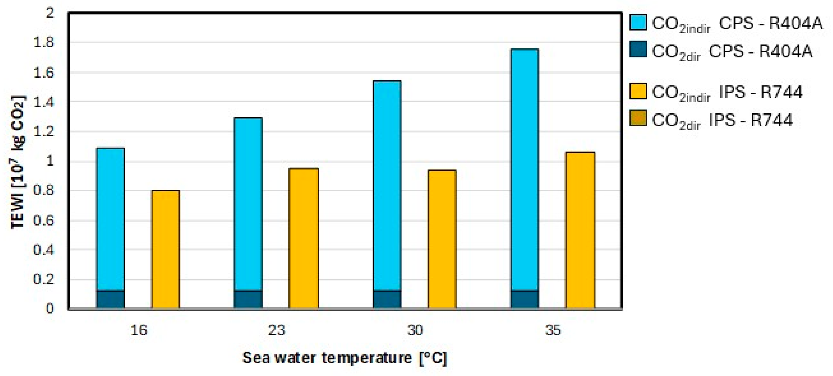
The combination of the higher COP and the lower GWP of R744, compared to R404A (GWP = 3922 [13]), results in a clear environmental advantage. This is demonstrated through the TEWI comparison in Figure 9.
As shown, the IPS using R744 achieves a TEWI reduction of 26–40% relative to the R404A-based CPS. Direct emissions are negligible in the innovative scenario, while they account for approximately 10% of total emissions in the R404A-based CPS. This negligible contribution for R744 supports the assumption that the adopted refrigerant charge does not influence the environmental comparison. Indirect emissions are also significantly reduced, between 18% and 35%.
The IPS with R744 demonstrates a significant improvement over CPS with R404A, suggesting that the introduction of phase separator and energy recovery devices such as ejectors can partially offset the intrinsic limitations of R744. These findings are in agreement with previous research [58], confirming that this ejector integration can effectively recover expansion losses and enhance overall cycle performance. Therefore, the development of optimized multi-ejector modules and adaptive control strategies may represent a promising direction for future improvements [59].

3.2. Air Conditioning Systems

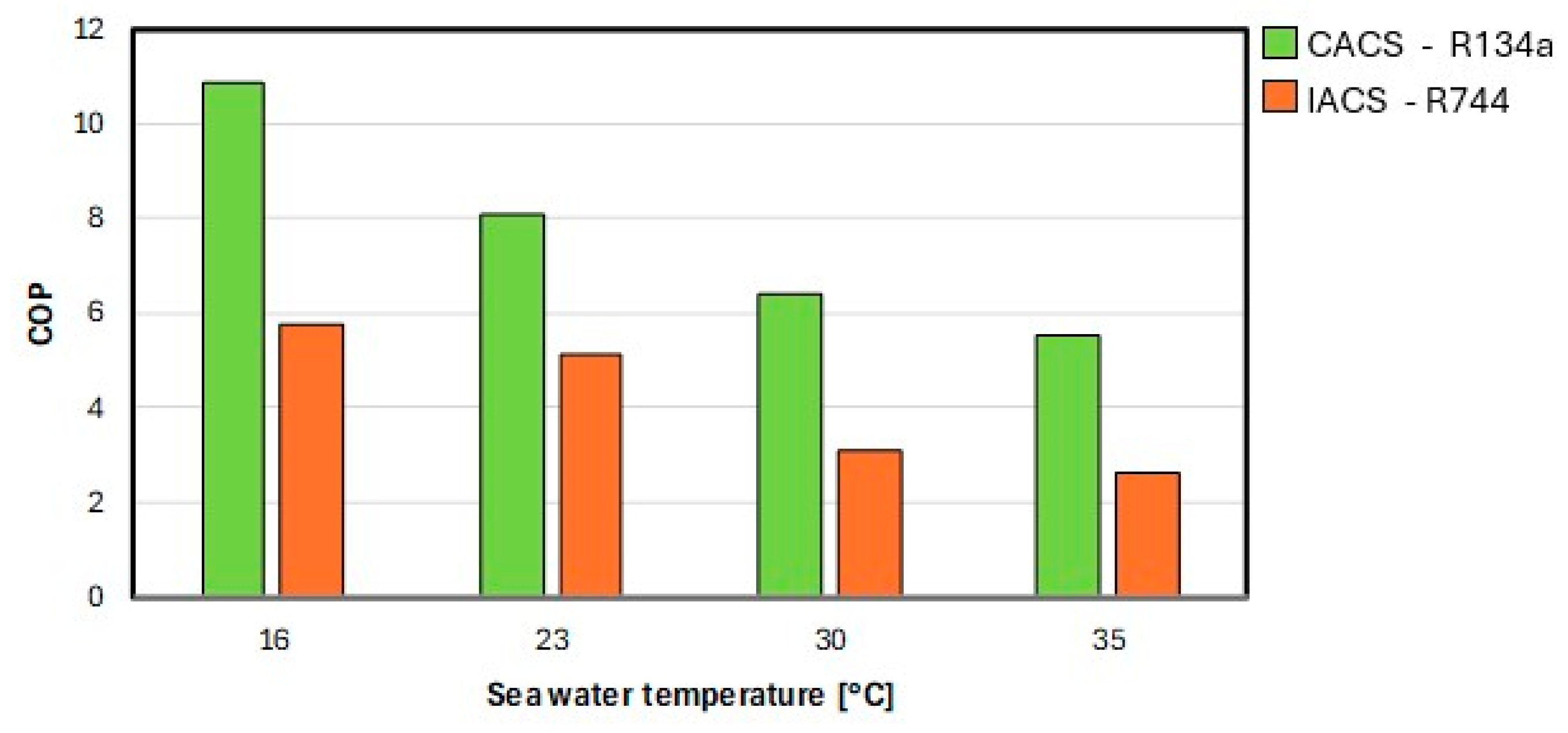
In the case of the R744-based IACS, the adoption of two evaporators reduces the temperature difference between the refrigerant and the cold source, thereby decreasing external entropy generation compared to a configuration featuring a single evaporator. The inclusion of the ejector increases the suction pressure and therefore enhances the overall cycle efficiency. However, thermodynamic losses in the transcritical R744 cycle remain significant, leading to relatively low COP values. The limited influence of the evaporator optimization on the global system performance is consistent with the literature findings, which show that in CO2 ejector-based refrigeration systems, the contribution of the evaporator to total entropy generation is minimal [27,60], whereas major losses are associated with the gas cooler, expansion valves, ejector and compressors [27]. This behaviour can be observed in Figure 10, which shows the COP comparison between the R134a-based CACS and the IACS employing R744 at different sea water temperatures.
The CACS using R134a achieves COP values ranging from 5.5 to 10.9. The high COP value observed here, as well as in other air conditioning circuits discussed later, is obtained for a sea water temperature of 16 °C. It should be noted that these results correspond to a numerical evaluation, and the temperature difference between the thermal reservoirs with which the condenser and evaporator exchange thermal energy is relatively small, considering that chilled water is produced at 7 °C and returns at 12 °C [12]. Such elevated COP values are consistent with results reported in similar numerical analyses in the literature [35,40].
Under the same conditions, the adoption of the IACS with R744 leads to a performance reduction of 37–53% compared with the CACS operating with R134a (GWP = 1490 [13]).
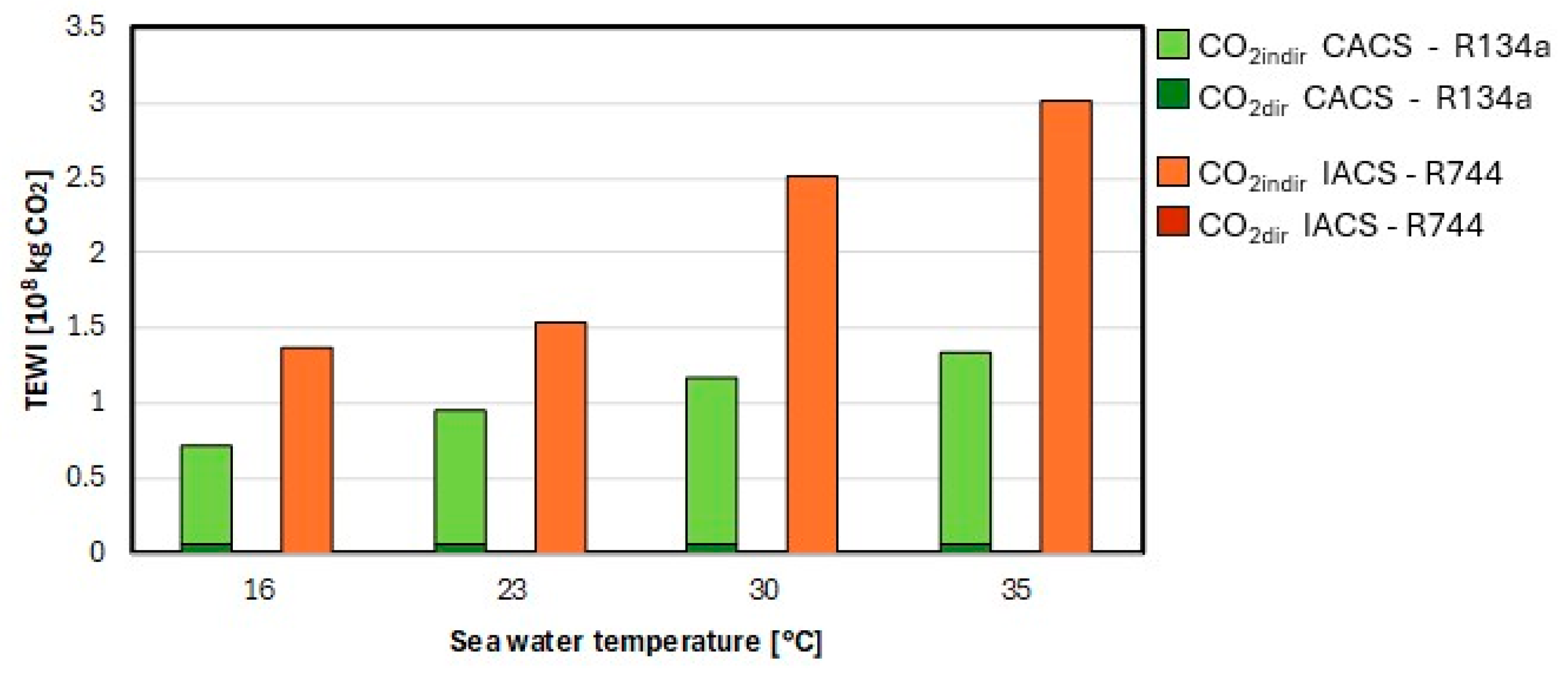
This reduction in efficiency leads to significantly increased energy demand, as reflected in the TEWI trend shown in Figure 11.
Direct emissions from the IACS with R744 are negligible with respect to those associated with the R134a-based CACS (close to 0%), confirming that the assumption of equal refrigerant charge has no significant influence on the environmental assessment, given the very low GWP of R744. However, the lower performance of the IACS with R744 results in a significantly higher indirect impact, causing an increase of 63–125% in TEWI, observed in comparison of the CASC using R134a.
The results indicate that, despite the adoption of advanced cycle architectures (e.g., ejector-based systems and internal heat exchangers), IACS with R744 still exhibits lower efficiencies than CACS with R134a: the lower isentropic efficiency of compressor and the need to reject heat to relatively warm sea water limit the potential of R744 to achieve competitive COP values and thus lower GHG emissions. However, the GWP of the R744 is very low and ensures compliance with regulatory requirements.

3.3. HVAC&R Systems

On a cruise ship, both provision and air conditioning systems are installed and operate together as HVAC&R systems. Therefore, the sustainability of adopting CO2 as a refrigerant must be assessed at the integrated HVAC&R system level, considering the combined operation of both provision and air conditioning plants.

3.3.1. CPS/CACS with HFCs and IPS/IACS with R744

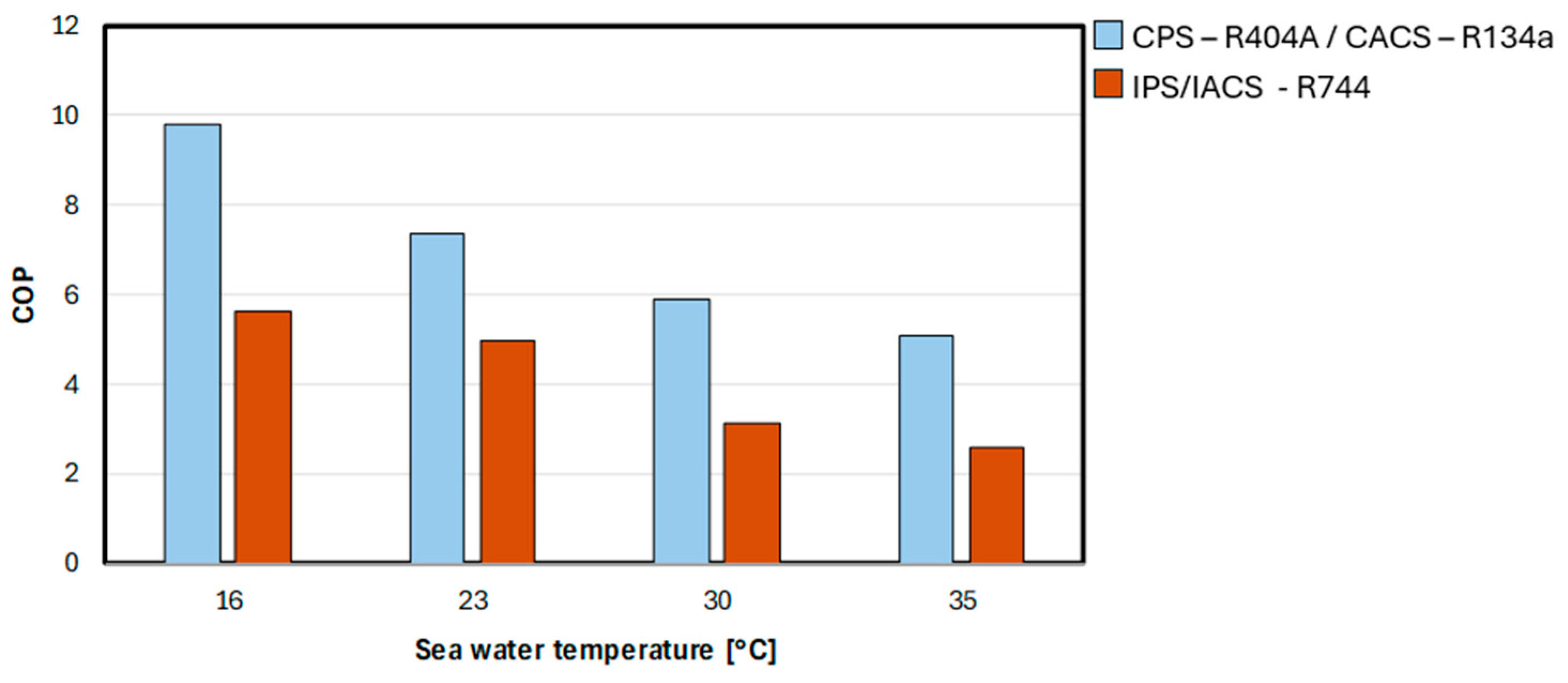
By comparing the sustainability of the current situation, where a cruise ship is equipped with the CPS and CACS using HFCs versus potential installation of the IPS and IACS with R744, the latter systems behave more inefficiently. This is clearly illustrated in Figure 12, which presents a performance comparison between conventional HVAC&R systems operating with HFCs and innovative HVAC&R systems operating with R744.
As shown, the COP values of the innovative HVAC&R systems operating with R744 system are consistently lower than those of conventional HFCs unit, with reductions of 32–49%.
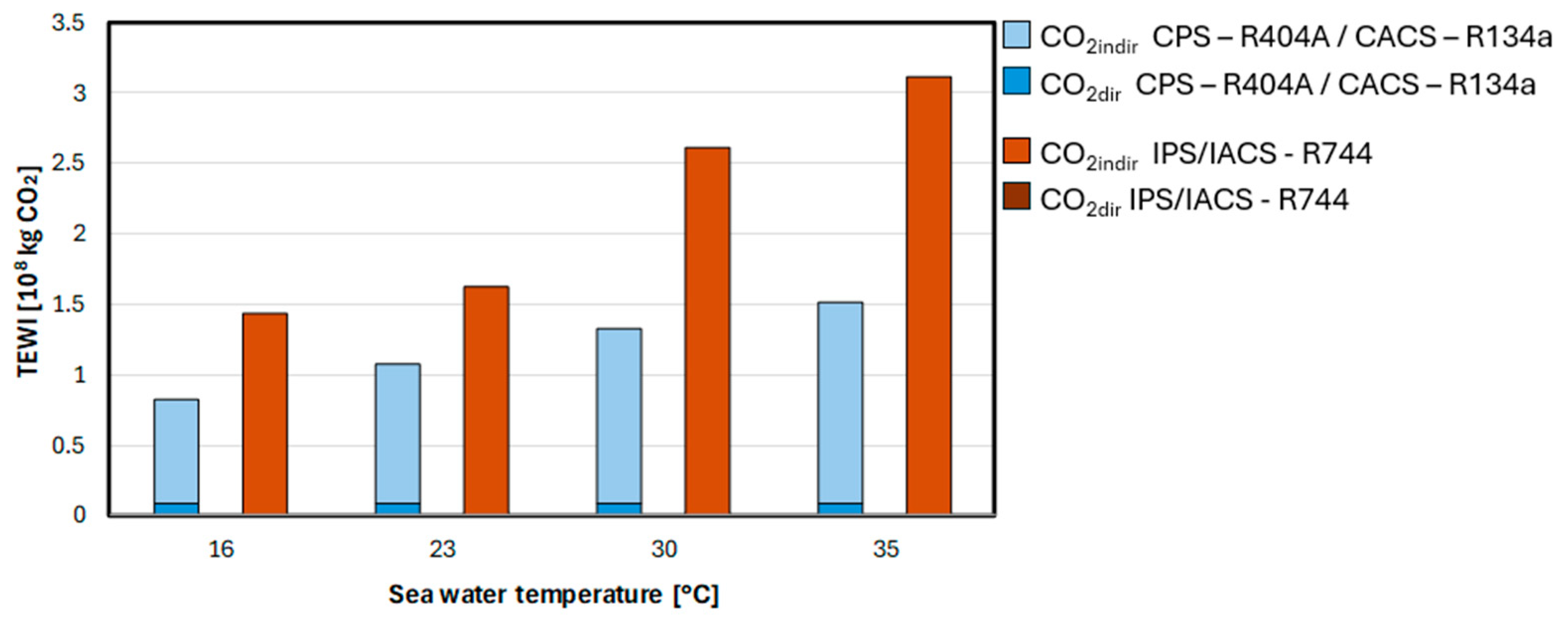
This drop in efficiency translates into significantly higher energy consumption during operation as expressed through the TEWI trend in Figure 13.
As shown, while the contribution of direct emissions is minimal in the innovative system, the total TEWI values increase by 52–106%. This rise is mainly attributed to the large share of indirect emissions generated by the low energy efficiency of R744-based configurations, which leads to higher electricity consumption compared to HFCs-based systems. It is important to stress that these results are largely driven by the air conditioning component of HVAC&R systems.
To enhance the COP of these systems and thereby reduce indirect emissions, future developments of this work could focus on an advanced exergy analysis combined with the assessment of the coefficient of structural bonds (CSB) in order to evaluate the inherent potential for performance improvement of the analyzed refrigeration cycles. Based on the outcomes of such analysis, the most investigated and promising approaches aimed at minimizing exergy losses and improving component efficiencies would concern compact gas coolers equipped with split fins, which have been shown to reduce thermal resistance and minimize exergy destruction across the heat exchange process [61]. Furthermore, compressors featuring separated suction and discharge chambers are designed to limit heat transfer between the discharge and suction sides within the cylinder heads, leading to higher isentropic efficiencies [62]. Finally, the integration of multi-ejector modules enables operation of the evaporators in flooded mode, which improves heat transfer effectiveness and overall system efficiency [63]. Moreover, one of the promising ways to increase the efficiency of vapour compression refrigeration machines is their combination with heat-driven systems that can utilize waste heat. Several studies in the literature have analyzed basic vapour compression refrigeration cycles in which the compressor is powered by a power cycle absorbing heat from the engine exhaust gases [64,65,66]. This approach contributes to reduce the emissions associated with the combustion of fossil fuels used to power shipboard refrigeration systems [67]. However, due to the complex layout and the high space occupancy rate of the steam power cycle, it may not represent the most efficient solution for marine waste heat recovery [68] due to the introduction of significant technical challenges for maritime applications [65].
However, when the provision and air conditioning units are considered jointly, as in an onboard HVAC&R plant, the overall environmental performance is largely governed by the air conditioning system, which accounts for the majority of energy consumption. This indicates that achieving full decarbonization through R744 alone would require major technological progress in high-capacity, transcritical R744 chillers.
Therefore, at the current stage, at the integrated HVAC&R system level, the use of R744, even within innovative configurations, cannot yet be recommended due to the relatively low efficiencies leading to high indirect emissions. Nevertheless, since current regulations are increasingly promoting the adoption of R744, given its safety and very low direct environmental impact, which is particularly relevant in the marine environment due to continuous vibrations, it remains essential to further enhance the technology of systems exclusively employing this refrigerant. It should be emphasized that the results presented are specific to the reference case considered in this study, representative of a medium-sized cruise ship, for which particular compressor types are selected according to typical design practices and literature sources. In particular, screw compressors are considered for R404A provision systems, while centrifugal compressors are adopted for R134a air conditioning systems, as commonly applied in marine HVAC&R installations at the considered cooling capacity values [69]. Conversely, reciprocating compressors are the preferred choice for R744 applications, since the sealing of the cylinder, mainly through piston rings, is more effective for high-pressure gases compared to other compressor types [70]. However, for systems of different scales, the optimal compressor selection could vary. For example, in smaller or larger capacity ranges, conventional systems may adopt other compressors because they are more cost-effective for those cooling capacities [71], while in large-scale R744-based systems, reciprocating compressors may handle limited mass flow rates, thus requiring multiple units in parallel [12]. Research is therefore ongoing on the development of rotary compressors specifically adapted for R744 operation [55]. These variations directly influence the overall compressor efficiencies and, consequently, the global system performance. As compressors significantly contribute to total cycle inefficiency [27,60], a change in system scale could lead to either mitigation or amplification of the differences in COP and TEWI between conventional HFCs-based and innovative R744-based configurations. The present work should thus be regarded as a benchmark and starting point for assessing the potential of R744-based HVAC&R systems for medium-sized cruise ships. Future analyses should extend this comparison to different ship sizes and configurations in order to support an effective and well-targeted energy transition toward more sustainable refrigeration technologies in the maritime sector.
While progressing toward full R744 adoption, potential transitional solutions may include the retrofit to improve conventional HFCs-based technologies or the adoption of hybrid HFO–R744 configurations. Accordingly, in the following subsections, the innovative layouts previously described for R744 are analyzed when operating with HFCs, together with cascade systems employing R1234yf in the second stage and R744 in the first stage.
It is important to emphasize that R404A and R134a are not proposed in this study as long-term or future refrigerant solutions, given their high GWP values and the forthcoming phase-down measures established by the Kigali Amendment and the F-Gas Regulation. Likewise, R1234yf cannot be regarded as a definitive alternative due to the environmental concerns associated with the atmospheric formation of TFA, an issue that, however, is not yet addressed within the current regulatory framework.
Nevertheless, the analysis of these fluids allows identifying promising short-term and transitional solutions that could facilitate the progressive shift toward fully R744-based technologies as their technical maturity increases. Indeed, as specified above, new regulatory measures related to refrigerants are expected to take effect by 1 January 2030, and the phase-down schedules established by international agreements are designed to be gradual, extending over decades. Moreover, it is not realistic to envision a complete replacement of all existing onboard systems with R744-based installations in the short term. The adoption of R744 involves significant technological constraints: due to the high operating pressures, R744 cannot be considered a drop-in refrigerant, and existing systems would require a complete redesign. In addition, the components must withstand higher mechanical stresses, resulting in increased system complexity and cost. The application of R744 in the maritime sector is still at an early stage of technological maturity and further development is needed to ensure reliability and operational robustness. This aspect is particularly relevant because the crew’s primary duties are focused on ship propulsion while maintenance and troubleshooting of refrigeration systems are often given low priority [12]. Introducing a less consolidated and more complex technology could therefore exacerbate operational challenges.

3.3.2. CPS/CACS with HFCs and IPS/IACS with HFCs

For the scope declared at the end of the previous subsection, the analysis is also conducted on the innovative HVAC&R systems originally designed for R744 (IPS and IACS presented in Figure 3 and Figure 5) but operating with HFCs. Specifically, R404A is considered for the IPS, which is assumed to use a screw compressor, with pressure downstream of the ejector as a variable parameter. Meanwhile, R134a is examined for the IACS, which is assumed to use a centrifugal compressor. The cooling evaporator is assumed to work at the same evaporation temperature as that of the IACS using R744 for consistency in the comparison.
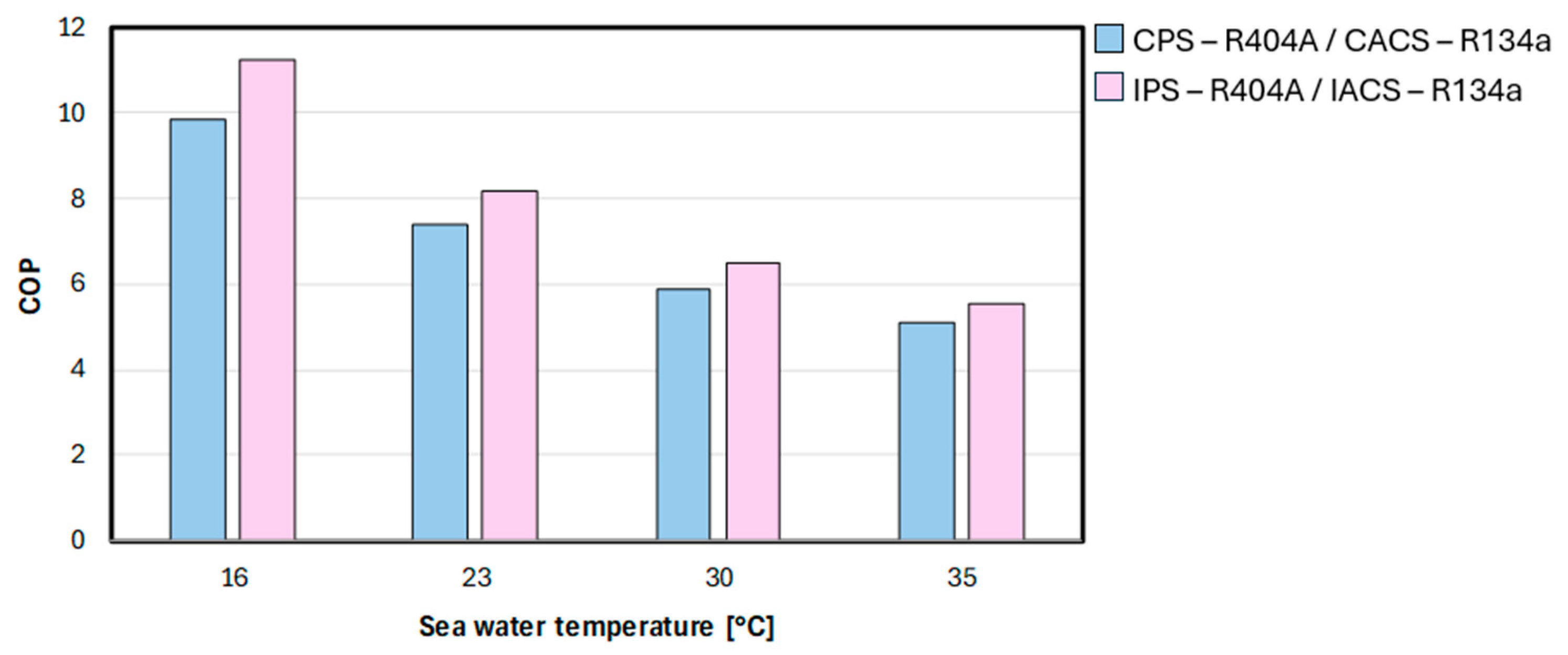
The comparison in terms of COP between conventional and innovative HVAC&R systems, both operating with HFCs, is shown in Figure 14.
As illustrated, adopting innovative configurations with HFCs leads to improved energy performance by over 14% at a sea water temperature of 16.0 °C, while at 35.0 °C the improvement is approximately 10%.
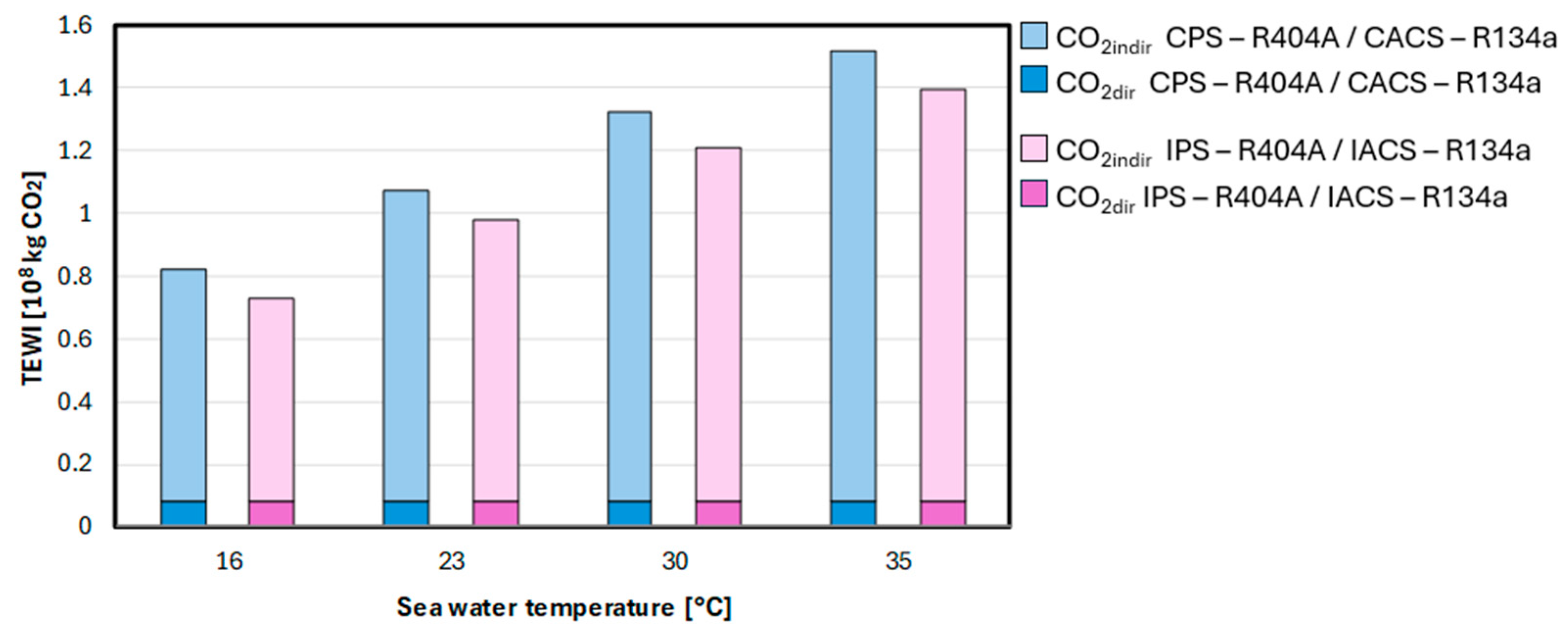
This gain in efficiency directly translates into lower environmental impact as evident from the TEWI comparison in Figure 15.
The comparison highlights a reduction in TEWI around 10% across the sea water temperature range. This improvement is related to the decrease in indirect emissions, up to 13%. This comparison is based on the assumption of identical refrigerant charges which, however, refer to conventional rather than innovative circuit layouts. To qualitatively assess the influence of this approximation, a numerical sensitivity evaluation was carried out, showing that when the refrigerant charge of both the IPS and IACS configurations is increased by 60%, the advantage becomes less pronounced, with the overall TEWI reducing to about 5% with respect to conventional HVAC&R systems.

3.3.3. CPS/CACS with HFCs and CS with R1234yf-R744

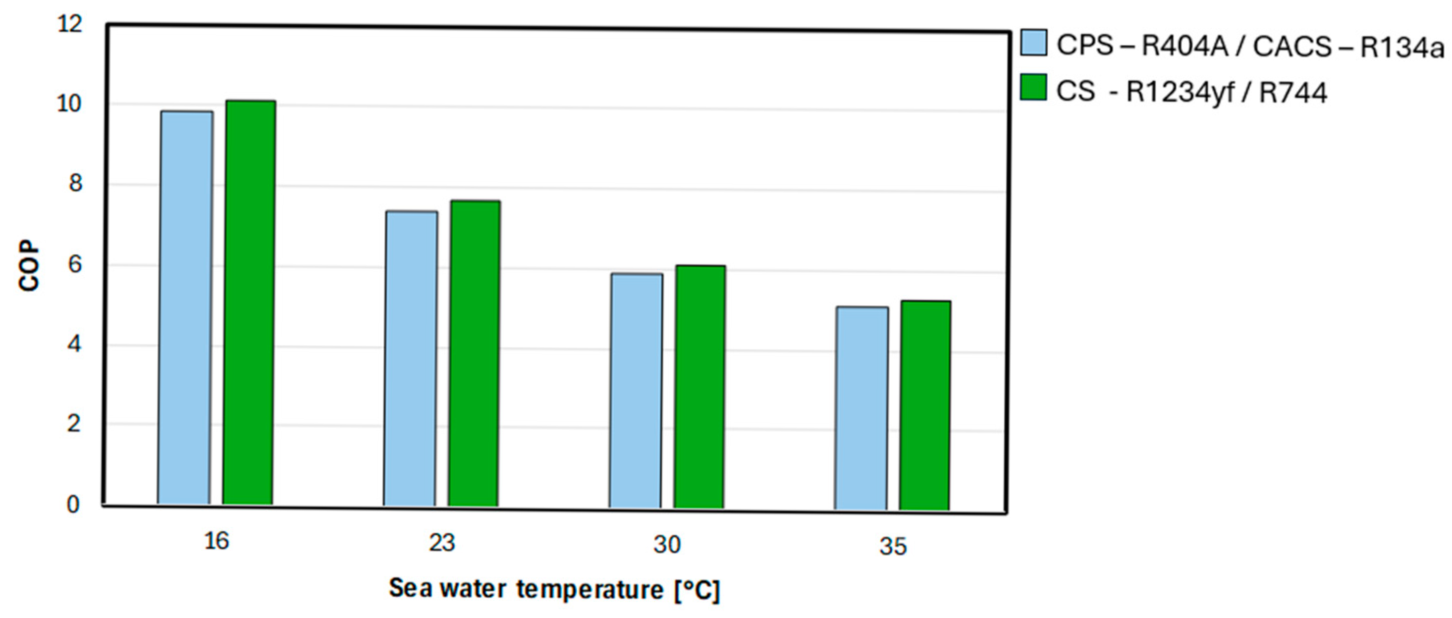
Pending advancements in technological know-how for R744-total based systems, the CS may represent a more viable alternative to traditional HFCs-based systems compared to IPS and IACS with R744. Therefore, a CS utilizing R1234yf in the high stage and R744 in the low stage is considered in the analysis as an innovative HVAC&R system. Figure 16 shows the COP comparison between the conventional HVAC&R systems operating with HFCs and the CS with R1234yf-R744.
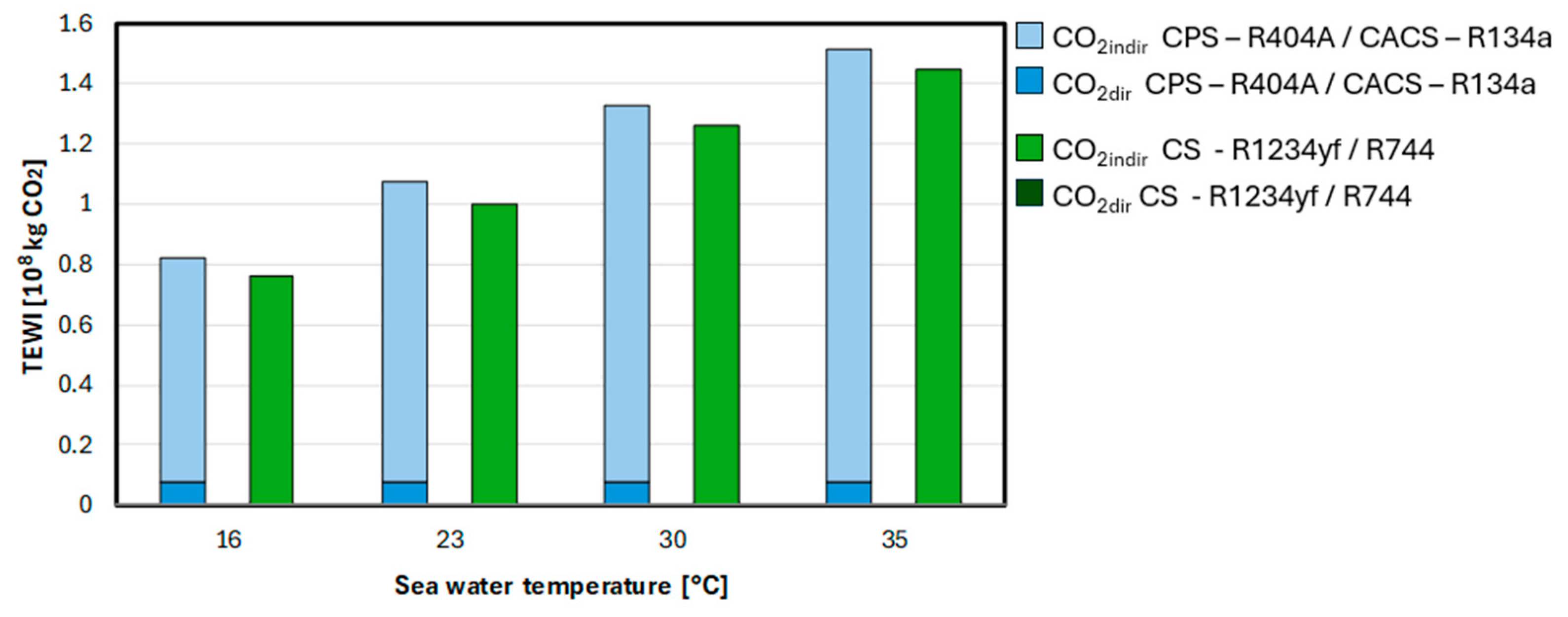
As it can be noticed, across all sea water temperatures the CS delivers higher COP values than the conventional HVAC&R systems with HFCs, with an improvement of up to 4%. Although this percentage may appear modest, it must be stressed that the CS operates with refrigerants fully compliant with current regulations, leading to a drastic reduction in direct environmental impact, as illustrated in Figure 17.
Indeed, the direct impact of the CS amounts to only 0.24% of that of the conventional HVAC&R systems, owing to the very low GWP of R1234yf, equal to 4 [13]. This finding, consistent with the behaviour of R744-based systems, further confirms that the assumption of identical refrigerant charges does not distort the comparative trends in TEWI. Furthermore, this negligible direct impact, combined with the higher efficiency of the CS, results in a reduction in TEWI of up to 8%.
The key point to highlight is that, compared to conventional HVAC&R systems, the CS not only achieves better efficiency but also relies on regulation-approved refrigerants with a lower environmental impact, supporting their role as feasible intermediate solutions toward full natural refrigerant adoption. This confirms the potential of subcritical R744 cycles for maritime applications. These results are aligned with those reported in the literature for HFOs-R744 systems [72].

4. Conclusions

In this paper, a comparison was conducted between conventional systems operating with HFCs and theoretical innovative configurations designed for efficient operation with R744. The aim was to analyze the feasibility of utilizing R744 for medium-sized cruise ships to enhance the environmental sustainability and comply with current regulations.
The numerical results obtained show that, at present, replacing conventional systems with innovative technologies employing exclusively R744 is not yet favourable for decarbonization as it results in a reduction in COP by up to 49% and in TEWI values that can exceed more than twice those of conventional HVAC&R systems with HFCs. However, given the high safety and the very low direct impact of R744, further improvements in the technologies employing this refrigerant are essential and can be achieved, as a future development, through an analysis of the inherent potential by means of the CSB. In the literature, such improvements mainly concern advanced gas coolers with enhanced thermal exchange performance, more efficient compressors and multi-ejector configurations that improve overall system performance. In addition, the integration of R744-based HVAC&R systems with other shipboard subsystems, such as waste heat recovery and combined energy systems, may represent a promising direction for future research, as it could further enhance the overall energy efficiency of shipboard installations once the technology achieves greater maturity. However, this would entail a higher level of system complexity, which adds to the fact that, despite the demonstrated technical feasibility, economic aspects, such as the high cost of components and the complexity of maintenance, still represent a significant barrier, requiring further research and technological development.
It is important to note that these results are contingent upon the specific hypotheses made during the analysis, including the assumption of a static operational framework that does not account for dynamic system utilization over time, which may influence long-term performance and reliability. This aspect will therefore be important to address in future developments. Consequently, the present results provide a rough estimate that R744-based technologies still require further improvements.
In the meantime, transitional solutions could represent a more pragmatic pathway. In particular, the retrofit of conventional HFCs-based systems through the adoption of architectures originally conceived for R744 can lead to performance improvements of up to 14% and a reduction in environmental impact by around 10%. Such configurations can therefore be regarded as intermediate steps toward the progressive adoption of low-GWP refrigerants.
Pending advancements in technological know-how that enables efficient use of R744, a promising transitional alternative may be to adopt hybrid solutions that comply with international treaties, i.e., cascade system, which combines R1234yf for the second stage with R744 for the first stage, promoting a subcritical cycle operation. This system is characterized by performance and overall environmental impact comparable to those of conventional HFCs-based systems, with the additional advantage of employing a refrigerant that is fully compliant with current regulations and requires a lower system complexity than innovative configurations wih HFCs. This could serve as a transitional platform to build operational experience with R744 onboard while reducing environmental impact.
In this context, the present study should be regarded as a first step, providing preliminary theoretical and numerical analyses to assess the feasibility of adopting R744 in naval refrigeration. While the findings highlight both opportunities and current limitations, it is crucial to emphasize the need for further research, particularly through empirical validation, if the maritime sector expresses concrete interest in this technological pathway. Beyond its technical relevance, the potential implementation of such solutions could also contribute to fostering sustainable innovation and supporting the development of the blue economy, thereby promoting more competitive and environmentally responsible maritime activities.

Author Contributions

Conceptualization, M.D., F.P., A.G., C.A. and A.M.; Methodology, M.D., F.P., A.G., C.A. and A.M.; Investigation, M.D., F.P. and A.G.; Data curation, M.D., F.P. and A.G.; Writing—original draft, M.D., F.P. and A.G.; Writing—review & editing, M.D., F.P. and A.G.; Supervision, C.A. and A.M. All authors have read and agreed to the published version of the manuscript.

Funding

This research received no external funding.

Data Availability Statement

The raw data supporting the conclusions of this article will be made available by the authors on request.

Conflicts of Interest

The authors declare no conflicts of interest.

Nomenclature

Symbols
Q ˙ r e f Cooling capacity [kW]
TTemperature [°C]
pPressure [bar]
hSpecific enthalpy [kJ kg−1]
QQuality
m ˙ Mass flow rate [kJ s−1]
rcCompression ratio
ηisCompression isentropic efficiency
εInternal heat exchanger efficiency
ФEntrainment ratio
ηejEjector efficiency
ηemElectric motor efficiency
CO2,dirDirect contribution to global warming [kgCO2]
CO2,indirIndirect contribution to global warming [kgCO2]
COPCoefficient of performance
GHGGreenhouse gas
GWPGlobal warming potential [kgCO2∙kgrefrigerant−1]
HAnnual operating hours [h∙years−1]
PLAccidental refrigerant leaks per year [% refrigerant∙years−1]
PRRecycling rate [% refrigerant charge]
RCRefrigerant charge [kg]
TEWITotal equivalent warming impact [kgCO2]
VPlant useful life [years]
αCO2 emissions from power conversion [kgCO2∙kWhe−1]
Abbreviations
CCompressor
COCondenser
GCGas cooler
EVEvaporator
ExVExpansion valve
IHXInternal heat exchanger
PSPhase separator
EJEjector
PPump
AHUAir handling unit
Subscripts
cCooling
fFreezing
acAir conditioning
lLiquid
vVapour

References

  1. Saeed, M.Z.; Hafner, A.; GabrielII, C.; Tolstorebrov, I.; Widell, K. CO2 Refrigeration System Design and Optimization for LNG Driven Cruise Ships. In Proceedings of the 9th Conference on Ammonia and CO2 Refrigeration Technologies, Ohrid, North Macedonia, 16–17 September 2021. [Google Scholar]
  2. International Chamber of Shipping; World Shipping Council. MEPC 76/7/29 Reduction of GHG Emissions from Ships: Refrigerated Container Cargoes; International Maritime Organization: London, UK, 2021. [Google Scholar]
  3. Ruiz, V. Analysis of Existing Refrigeration Plants Onboard Fishing Vessels and Improvement Possibilities. In Proceedings of the Second International Symposium on Fishing Vessel Energy Efficiency E-Fishing, Vigo, Spain, 22–24 May 2012. [Google Scholar]
  4. Carrasco, P.; Bendaña, R.; Paredes, A.; Michinel, H.; Fernández de Córdoba, P.; Arce, M.E.; Zaragoza, S. Analysis of Key Variables for Energy Efficiency in Warships. Proc. Inst. Mech. Eng. Part M J. Eng. Marit. Environ. 2020, 234, 234. [Google Scholar] [CrossRef]
  5. Jasper, F.; Shinichi, H.; Shuang, Z.; Paula, P. Fourth IMO GHG Study 2020 Full Report; International Maritime Organization: London, UK, 2021. [Google Scholar]
  6. Mallouppas, G.; Yfantis, E.A. Decarbonization in Shipping Industry: A Review of Research, Technology Development, and Innovation Proposals. J. Mar. Sci. Eng. 2021, 9, 415. [Google Scholar] [CrossRef]
  7. Winfried Schwarz, B.; Rhiemeier, J.-M. The Analysis of the Emissions of Fluorinated Greenhouse Gases from Refrigeration and Air Conditioning Equipment Used in the Transport Sector Other than Road Transport and Options for Reducing These Emissions Maritime, Rail, and Aircraft Sector Prepared for the European Commission (DG Environment); European Commission: Brussels, Belgium, 2007. [Google Scholar]
  8. Heath, E.A. Amendment to the Montreal Protocol on Substances That Deplete the Ozone Layer (Kigali Amendment). Int. Leg. Mater. 2017, 56, 56. [Google Scholar] [CrossRef]
  9. Regulation (EU) 2024/573 of the European Parliament and of the Council; Official Journal of the European Union: Luxembourg, 2024.
  10. Glavan, I.; Poljak, I.; Mustać, M.; Lonić, I. Natural Refrigerant on Board Marine Vessels. Pomor. Zb. 2022, 62, 62. [Google Scholar] [CrossRef]
  11. Minetto, S.; Fabris, F.; Marinetti, S.; Rossetti, A. A Review on Present and Forthcoming Opportunities with Natural Working Fluids in Transport Refrigeration. Int. J. Refrig. 2023, 152, 152. [Google Scholar] [CrossRef]
  12. Hafner, I.A.; Gabrielii, C.H.; Widell, K. Refrigeration Units in Marine Vessels; TemaNord; Nordic Council of Ministers: Copenhagen, Denmark, 2019; ISBN 9789289359412. [Google Scholar]
  13. ASHRAE Standard 34; Designation and Safety Classification of Refrigerants. ASHRAE: Peachtree Corners, GA, USA, 2019.
  14. Kim, M.H.; Pettersen, J.; Bullard, C.W. Fundamental Process and System Design Issues in CO2 Vapor Compression Systems. Prog. Energy Combust. Sci. 2004, 30, 30. [Google Scholar] [CrossRef]
  15. Bansal, P. A Review—Status of CO2 as a Low Temperature Refrigerant: Fundamentals and R&D Opportunities. Appl. Therm. Eng. 2012, 41, 41. [Google Scholar]
  16. Rhiemeir, J.-M.; Harnisch, J.; Ters, C. Comparative Assessment of the Climate Relevance of Supermarket Refrigeration Systems and Equipment Climate Change; Federal Environment Agency: Dessau-Roßlau, Germany, 2009; ISSN 1862-4359. [Google Scholar]
  17. Aprea, C.; Maiorino, A. An Experimental Evaluation of the Transcritical CO2 Refrigerator Performances Using an Internal Heat Exchanger. Int. J. Refrig. 2008, 31, 31. [Google Scholar] [CrossRef]
  18. Sánchez, D.; Patiño, J.; Llopis, R.; Cabello, R.; Torrella, E.; Fuentes, F.V. New Positions for an Internal Heat Exchanger in a CO2 Supercritical Refrigeration Plant. Experimental Analysis and Energetic Evaluation. Appl. Therm. Eng. 2014, 63, 63. [Google Scholar] [CrossRef]
  19. Liu, S.; Wang, J.; Dai, B.; Yang, X.; Nian, V.; Li, H.; Yuan, J. Alternative Positions of Internal Heat Exchanger for CO2 Booster Refrigeration System: Thermodynamic Analysis and Annual Thermal Performance Evaluation. Int. J. Refrig. 2021, 131, 131. [Google Scholar] [CrossRef]
  20. Llopis, R.; Nebot-Andrés, L.; Sánchez, D.; Catalán-Gil, J.; Cabello, R. Subcooling Methods for CO2 Refrigeration Cycles: A Review. Int. J. Refrig. 2018, 93, 93. [Google Scholar] [CrossRef]
  21. Nebot-Andrés, L.; Calleja-Anta, D.; Sánchez, D.; Cabello, R.; Llopis, R. Experimental Assessment of Dedicated and Integrated Mechanical Subcooling Systems vs Parallel Compression in Transcritical CO2 Refrigeration Plants. Energy Convers. Manag. 2022, 252, 252. [Google Scholar] [CrossRef]
  22. Fangtian, S.; Yitai, M. Thermodynamic Analysis of Transcritical CO2 Refrigeration Cycle with an Ejector. Appl. Therm. Eng. 2011, 31, 31. [Google Scholar] [CrossRef]
  23. Elbarghthi, A.F.A.; Hafner, A.; Banasiak, K.; Dvorak, V. An Experimental Study of an Ejector-Boosted Transcritical R744 Refrigeration System Including an Exergy Analysis. Energy Convers. Manag. 2021, 238, 238. [Google Scholar] [CrossRef]
  24. Chesi, A.; Esposito, F.; Ferrara, G.; Ferrari, L. Experimental Analysis of R744 Parallel Compression Cycle. Appl. Energy 2014, 135, 135. [Google Scholar] [CrossRef]
  25. Gullo, P.; Elmegaard, B.; Cortella, G. Advanced Exergy Analysis of a R744 Booster Refrigeration System with Parallel Compression. Energy 2016, 107, 107. [Google Scholar] [CrossRef]
  26. Pigani, L.; Boscolo, M.; Pagan, N. Marine Refrigeration Plants for Passenger Ships: Low-GWP Refrigerants and Strategies to Reduce Environmental Impact. Int. J. Refrig. 2016, 64, 64. [Google Scholar] [CrossRef]
  27. Syngounas, E.; Tsimpoukis, D.; Bellos, E.; Koukou, M.K.; Tzivanidis, C.; Vrachopoulos, M.G. Energy and Exergy Performance Investigation of a Transcritical CO2 Vapor Ejector-Based Refrigeration System for Marine Provision Plants. Appl. Therm. Eng. 2025, 269, 269. [Google Scholar] [CrossRef]
  28. Andersen, H.; Saeed, M.Z.; Hafner, A.; Gabriellii, C.H. Investigation of CO2 Refrigeration System and Thermal Energy Storage for Passenger Ships. In Proceedings of the 10th Conference on Ammonia and CO2 Refrigeration Technologies, Ohrid, North Macedonia, 27–29 April 2023. [Google Scholar]
  29. Available online: https://weatherspark.com (accessed on 3 July 2024).
  30. World Sea Temperatures. Available online: https://www.seatemperature.org/ (accessed on 3 July 2024).
  31. Lemmon, E.W.; Bell, I.H.; Huber, M.L.; McLinden, M.O. NIST Standard Reference Database 23, version 10.0; Reference Fluid Thermodynamic and Transport Properties-REFPROP; National Institute of Standards and Technology: Gaithersburg, MD, USA, 2018. [Google Scholar]
  32. Aprea, C.; Greco, A.; Maiorino, A. An Experimental Evaluation of the Greenhouse Effect in the Substitution of R134a with CO2. Energy 2012, 45, 45. [Google Scholar] [CrossRef]
  33. Gullo, P.; Cortella, G. Theoretical Evaluation of Supermarket Refrigeration Systems Using R1234ze(E) as an Alternative to High-Global Warming Potential Refrigerants. Sci. Technol. Built Environ. 2016, 22, 22. [Google Scholar] [CrossRef]
  34. Hansen, T.M.; Haukås, H.T. Alternatives to HCFC as Refrigerant in Shipping Vessels; Nordic Council of Ministers: Copenhagen, Denmark, 2000. [Google Scholar]
  35. Wajs, J.; Mrozek, M.; Fornalik-Wajs, E. Combined Cold Supply System for Ship Application Based on Low GWP Refrigerants—Thermo-Economic and Ecological Analyses. Energy Convers. Manag. 2022, 258, 258. [Google Scholar] [CrossRef]
  36. Shestopalov, K.; Khliyeva, O.; Ierin, V.; Konstantinov, O.; Khliiev, N.; Neng, G.; Kozminykh, M. Novel Marine Ejector-Compression Waste Heat-Driven Refrigeration System: Technical Possibilities and Environmental Advantages. Int. J. Refrig. 2024, 158, 158. [Google Scholar] [CrossRef]
  37. Abdan, S.; Stosic, N.; Kovacevic, A.; Smith, I.; Deore, P. Identification and Analysis of Screw Compressor Mechanical Losses. In IOP Conference Series: Materials Science and Engineering; Institute of Physics Publishing: Bristol, UK, 2018; Volume 425. [Google Scholar]
  38. Zhang, Y.; Cai, M.; Kong, D. Overall Energy Efficiency of Lubricant-Injected Rotary Screw Compressors and Aftercoolers. In Proceedings of the 2009 Asia-Pacific Power and Energy Engineering Conference, Wuhan, China, 28–30 March 2009; pp. 1–5. [Google Scholar]
  39. Carrier AquaEdgeTM. Available online: https://www.carrier.com/marine-offshore/en/worldwide/products/chillers/water-cooled-chillers/19xr-xrv-two-stage/ (accessed on 30 June 2024).
  40. Tanninen, T. Passenger Ship Refrigeration—Dimensioning and Energy Saving Options. Master’s Thesis, Lappeenranta-Lahti University of Technology (LUT), Lappeenranta, Finland, 2020. [Google Scholar]
  41. Yang, C.; Liu, Z.; Liu, Y.; Wang, H.; Wang, Y.; Hu, D.; Wang, B.; Yang, J.; Chen, Y. Influence of Diffuser Vane Thickness on Centrifugal Compressor Performance. J. Phys. Conf. Ser. 2022, 2437, 2437. [Google Scholar] [CrossRef]
  42. Benini, E. Optimal Navier-Stokes Design of Compressor Impellers Using Evolutionary Computation. Int. J. Comut Fluid. Dyn. 2003, 17, 17. [Google Scholar] [CrossRef]
  43. Astolfi, S.P.M.; Gaetani, P. Politecnico Di Milano Design and Off-Design Analysis of a Multistage Centrifugal Compressor for an A-CAES Plant Co-Supervisor. Available online: https://www.politesi.polimi.it/retrieve/e463ca4a-b219-4b1e-a380-2e4f00a87595/Design%20and%20Off-Design%20Analysis%20of%20a%20Multistage%20Centrifugal%20Compressor%20for%20an%20A-CAES%20Plant.pdf (accessed on 15 October 2025).
  44. Moore, J.C. Electric Motors for Centrifugal Compressor Drives; General Electric Co.: Schenectady, NY, USA, 1974. [Google Scholar] [CrossRef]
  45. Bodys, J.; Hafner, A.; Banasiak, K.; Smolka, J.; Ladam, Y. Design and Simulations of Refrigerated Sea Water Chillers with CO2 Ejector Pumps for Marine Applications in Hot Climates. Energy 2018, 161, 161. [Google Scholar] [CrossRef]
  46. Gullo, P.; Hafner, A.; Banasiak, K. Transcritical R744 Refrigeration Systems for Supermarket Applications: Current Status and Future Perspectives. Int. J. Refrig. 2018, 93, 93. [Google Scholar] [CrossRef]
  47. Singh, S.; Selvnes, H.; Pardiñas, Á.Á.; Reddy, S.K.; Gupta, P.; Vaishak, S.; Arun, B.S.; Widell, K.N.; Elarga, H.; Hafner, A. Advanced R744 Solution for Supermarkets, Hotel Chillers and Maritime Applications in India. In Proceedings of the 15th IIR-Gustav Lorentzen Conference on Natural Refrigerants, Trondheim, Norway, 13–15 June 2022. [Google Scholar] [CrossRef]
  48. Hafner, A.; Försterling, S.; Banasiak, K. Multi-Ejector Concept for R-744 Supermarket Refrigeration. Int. J. Refrig. 2014, 43, 43. [Google Scholar] [CrossRef]
  49. Gullo, P.; Tsamos, K.M.; Hafner, A.; Banasiak, K.; Ge, Y.T.; Tassou, S.A. Crossing CO2 Equator with the Aid of Multi-Ejector Concept: A Comprehensive Energy and Environmental Comparative Study. Energy 2018, 164, 164. [Google Scholar] [CrossRef]
  50. Gambini, M.; Manno, M.; Vellini, M. Energy and Exergy Analysis of Transcritical CO2 Cycles for Heat Pump Applications. Sustainability 2024, 16, 7511. [Google Scholar] [CrossRef]
  51. Elbel, S.; Lawrence, N. Review of Recent Developments in Advanced Ejector Technology. Int. J. Refrig. 2016, 62, 62. [Google Scholar] [CrossRef]
  52. Elbel, S. Historical and Present Developments of Ejector Refrigeration Systems with Emphasis on Transcritical Carbon Dioxide Air-Conditioning. Int. J. Refrig. 2011, 34, 34. [Google Scholar] [CrossRef]
  53. Chen, X.; Su, Y.; Omer, S.; Riffat, S. Theoretical Investigations on Combined Power and Ejector Cooling System Powered by Low-Grade Energy Source. Int. J. Low-Carbon Technol. 2016, 11, 11. [Google Scholar] [CrossRef]
  54. Saeed, M.Z.; Widell, K.N.; Hafner, A.; Nordtvedt, T.S.; Svendsen, E.S. Integrated Thermal Storage and Heat Recovery of the CO2 Refrigeration System for Fishing Vessels. In Proceedings of the 14th IIR-Gustav Lorentzen Conference on Natural Refrigerants Refrigeration Science and Technology, Kyoto, Japan, 7–9 December 2020; International Institute of Refrigeration: Paris, France, 2020; Volume 2020, pp. 549–554. [Google Scholar]
  55. Fornasier, E.; Zilio, C.; Cecchinato, L.; Corradi, M.; Minetto, S. Natural Refrigerant CO2; Reulens, W., Ed.; International Institute of Refrigeration: Paris, France, 2009; ISBN ISBN9789081346733. [Google Scholar]
  56. Ribas, F.A.; Deschamps, C.J.; Fagotti, F.; Morriesen, A.; Dutra, T. Thermal Analysis of Reciprocating Compressors—A Critical Review. In Proceedings of the International Compressor Engineering Conference, West Lafayette, IN, USA, 14–17 July 2008. [Google Scholar]
  57. Andersen, H. Development of CO2 Refrigeration Systems and Thermal Energy Storage for Cruise Ships. Master’s Thesis, Norwegian University of Science and Technology, Trondheim, Norway, 2022. [Google Scholar]
  58. Shi, B.; Chen, M.; Chi, W.; Yang, Q.; Liu, G.; Zhao, Y.; Li, L. Effects of Internal Heat Exchanger on Two-Stage Compression Trans-Critical CO2 Refrigeration Cycle Combined with Expander and Intercooling. Energies 2022, 16, 115. [Google Scholar] [CrossRef]
  59. Elbarghthi, A.F.A.; Dvořák, V. Evaluation of Various Ejector Profiles on CO2 Transcritical Refrigeration System Performance. Entropy 2022, 24, 1173. [Google Scholar] [CrossRef]
  60. Yang, D.; Li, Y.; Xie, J.; Wang, J. Energetic and Entropy Analysis of a Novel Transcritical CO2 Two-Stage Compression/Ejector Refrigeration Cycle for Shipboard Cold Chamber. Therm. Sci. 2023, 27, 27. [Google Scholar] [CrossRef]
  61. Nekså, P.; Walnum, H.T.; Hafner, A. CO2—A Refrigerant from the Past with Prospects of Being One of the Main in the Future. In Proceedings of the 2010 9th IIR Gustav Lorentzen Conference 2010—Natural—Real Alternatives, Sydney, Australia, 12–14 April 2010. [Google Scholar]
  62. Javerschek, O.; Dittrich, G. Advanced Compressor Design and Various Systems for Commercial Applications with CO2. In Refrigeration Science and Technology Proceedings; C. A. Inc., Ed.; 2009; pp. 302–309. Available online: https://archive.r744.com/files/pdf_759.pdf (accessed on 24 November 2025).
  63. Nekså, P.; Hafner, A.; Bredsen, A.M.; Eikevik, T.M. CO2 as Working Fluid—Technological Development on the Road to Sustainable Refrigeration. In Proceedings of the 12th IIR Gustav Lorentzen Natural Working Fluids Conference, Edinburgh, UK, 21– 24 August 2016; pp. 21–24. [Google Scholar]
  64. Yu, A.; Su, W.; Lin, X.; Zhou, N.; Zhao, L. Thermodynamic Analysis on the Combination of Supercritical Carbon Dioxide Power Cycle and Transcritical Carbon Dioxide Refrigeration Cycle for the Waste Heat Recovery of Shipboard. Energy Convers. Manag. 2020, 221, 221. [Google Scholar] [CrossRef]
  65. Zhang, Q.; Luo, Z.; Zhao, Y.; Pavel, S. Thermodynamic Analysis and Multi-Objective Optimization of a Transcritical CO2 Waste Heat Recovery System for Cruise Ship Application. Energy Convers. Manag. 2021, 227, 227. [Google Scholar] [CrossRef]
  66. Zhang, F.; Zhou, J.; Liao, G.; You, M.; Yang, C. Improvement Design and Performance Assessment of Combined Cooling and Power System Using CO2 for Waste Heat Recovery. Appl. Therm. Eng. 2023, 228, 228. [Google Scholar] [CrossRef]
  67. Liang, Y.; Sun, Z.; Dong, M.; Lu, J.; Yu, Z. Investigation of a Refrigeration System Based on Combined Supercritical CO2 Power and Transcritical CO2 Refrigeration Cycles by Waste Heat Recovery of Engine. Int. J. Refrig. 2020, 118, 118. [Google Scholar] [CrossRef]
  68. Hou, S.; Zhang, F.; Yu, L.; Cao, S.; Zhou, Y.; Wu, Y.; Hou, L. Optimization of a Combined Cooling, Heating and Power System Using CO2 as Main Working Fluid Driven by Gas Turbine Waste Heat. Energy Convers. Manag. 2018, 178, 178. [Google Scholar] [CrossRef]
  69. Stoecker, W.F. Industrial Refrigeration Handbook; McGraw-Hill: New York, NY, USA, 1998; Volume 10. [Google Scholar]
  70. Suess, J.; Kruse, H. Efficiency of the Indicated Process of CO2 -Compressors. Int. J. Refrig. 1998, 21, 21. [Google Scholar]
  71. Giampaolo, T. Compressor Handbook: Principles and Practice; River Publishers: Gistrup, Denmark, 2010. [Google Scholar]
  72. Bellos, E.; Tzivanidis, C. A Theoretical Comparative Study of CO2 Cascade Refrigeration Systems. Appl. Sci. 2019, 9, 790. [Google Scholar] [CrossRef]
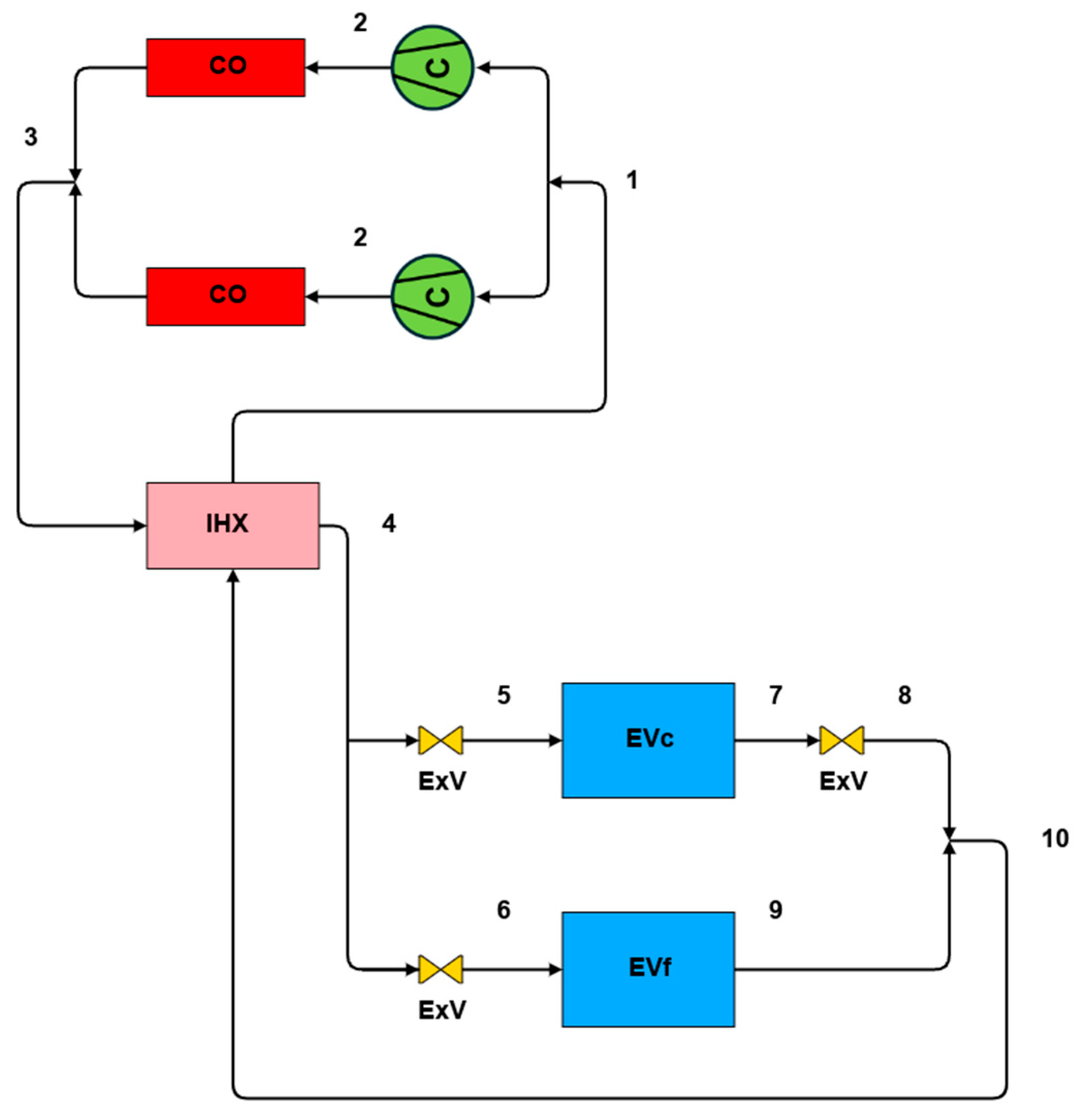
Figure 1. Simplified schematic of a CPS.
Energies 18 06211 g001
Figure 2. Simplified schematic of a CACS.
Energies 18 06211 g002
Figure 3. Simplified schematic of an IPS.
Energies 18 06211 g003
Figure 4. p–h diagram of R744 transcritical cycle in IPS.
Energies 18 06211 g004
Figure 5. Simplified schematic of an IACS.
Energies 18 06211 g005
Figure 6. p–h diagram of R744 transcritical cycle in IACS.
Energies 18 06211 g006
Figure 7. Simplified schematic of a CS.
Energies 18 06211 g007
Figure 8. COP comparison between the CPS with R404A and the IPS with R744.
Energies 18 06211 g008
Figure 9. TEWI comparison between the CPS with R404A and the IPS with R744.
Energies 18 06211 g009
Figure 10. COP comparison between the CACS with R134a and the IACS with R744.
Energies 18 06211 g010
Figure 11. TEWI comparison between the CACS with R134a and the IACS with R744.
Energies 18 06211 g011
Figure 12. COP comparison between the CPS/CACS with HFCs and the IPS/IACS with R744.
Energies 18 06211 g012
Figure 13. TEWI comparison between the CPS/CACS with HFCs and the IPS/IACS with R744.
Energies 18 06211 g013
Figure 14. COP comparison between the CPS/CACS with HFCs and the IPS/IACS with HFCs.
Energies 18 06211 g014
Figure 15. TEWI comparison between the CPS/CACS with HFCs and the IPS/IACS with HFCs.
Energies 18 06211 g015
Figure 16. COP comparison between the CPS/CACS with HFCs and the CS with R1234yf-R744.
Energies 18 06211 g016
Figure 17. TEWI comparison between the CPS/CACS with HFCs and the CS with R1234yf-R744.
Energies 18 06211 g017
Disclaimer/Publisher’s Note: The statements, opinions and data contained in all publications are solely those of the individual author(s) and contributor(s) and not of MDPI and/or the editor(s). MDPI and/or the editor(s) disclaim responsibility for any injury to people or property resulting from any ideas, methods, instructions or products referred to in the content.