Abstract
Railway barrier drives are key components of railway infrastructure and have a direct impact on traffic safety. Many of the commonly used drives are mechanical EEG-type barrier drives. EEG is a commercial designation of level-crossing gate drives produced by one of the Polish railway signalling equipment manufacturers, currently known as Alstom ZWUS Polska Sp. z o.o. (Katowice, Poland). These drives are characterized by their simple design and low cost, but limited efficiency and durability. Operational experience shows particular problems with the operation of this type of drive in winter conditions. This article presents an analysis of the impact of the selection of electric motors on the efficiency and reliability of level crossing drives. In addition to discussing the classic design with a PRMOa90-90 motor, commonly used in EEG drives, two proprietary solutions are presented: a commutator motor with rectangular neodymium magnets and a brushless DC motor (BLDC). Key operating parameters such as energy efficiency, starting torque, durability, maintenance requirements, and costs were compared. The results of the analyses indicate that the use of motors with neodymium magnets and BLDC solutions can significantly increase the efficiency and reliability of barrier drives, with each variant presenting a different profile of advantages and limitations.
1. Introduction
Barrier drives constitute fundamental components of the railway infrastructure, exerting a significant influence on the safety of both rail and road traffic. The reliability and efficiency of these systems are critical in establishing safety standards at level crossings and play a vital role in ensuring the continuity and seamless functioning of the general traffic control system. Therefore, there are a number of internal regulations of the carrier [,] and international standards [,,] relating to railway traffic safety. Due to the key role of railway barriers in ensuring safety, the design solutions used in these devices must be characterized by high durability, resistance to weather conditions, and long-term stability of parameters [,]. The subject of railway traffic safety is therefore of interest to many researchers [,,]. Barrier drives in Poland operate under highly variable weather conditions, with temperatures ranging from −30 °C to +40 °C and exposure to moisture, frost, and dust. Depending on the traffic intensity at a given crossing, the drives may perform from a few to several hundred operating cycles per day. These conditions lead to typical failures such as brush wear and commutator corrosion. Snowfall and icing in winter also require the drive to have a torque reserve so that it can operate even in more demanding conditions.
In recent years, the literature has shown a growing interest in the development of drive motors and their control and diagnostic systems. In older solutions (e.g., in Poland), as Kornaszewski and Nowak point out in their work [] on the example of the JEDG-50 drive, separately excited commutator motors with worm gearboxes predominated. With the development of permanent magnets manufacturing technology, permanent magnet motors (PMDC) have appeared. In practice, mechanical EEG drives are commonly used in Poland, in which the drive source is DC commutator motors with ferrite magnets. PRMOa90-90 motors manufactured by the Polish company Wamel are commonly used [,]. The advantages of classic magnetoelectric excitation commutator machines are undoubtedly their simple design, relatively low production costs, and ease of integration with the mechanical drive system. However, operational experience with drives using this type of motor indicates a number of limitations of this solution. These include, above all, low energy efficiency and increased failure rates due to the presence of brushes. In addition, the relatively low torque generated by magnets with a relatively low energy density causes problems during operation in winter conditions [,,].
In response to the above problems, attempts are being made to use alternative electric motor designs. This article presents two proprietary solutions developed as promising alternatives to classic DC motors with ferrite magnet excitation. The first is a commutator motor equipped with rectangular neodymium magnets, which allows for a significant increase in magnetic flux density, and thus higher torque while maintaining compact dimensions. The second is a brushless DC (BLDC) motor, a concept briefly introduced in earlier report [] which offers high efficiency and eliminates brushes and commutators through electronic commutation. It is worth noting that recent manufacturer documentation indicates [] that modern barrier drives increasingly employ low-voltage brushless motors; however, detailed scientific studies on this topic are still lacking.
The purpose of this article is to analyze the impact of the choice of electric motor type on the efficiency and reliability of barrier drives. The article compares three designs: the PRMOa90-90 ferrite commutator motor, commonly used in EEG drives, and two proprietary solutions: a commutator motor with rectangular neodymium magnets and a BLDC motor with a proprietary magnetic circuit design. The comparison is based on key operating parameters such as energy efficiency, generated torque, stall torque, durability, maintenance requirements, and drive system production and maintenance costs.
2. Materials and Methods
2.1. General Approach
The aim of the research was to compare three designs of electric motors intended for railway barrier drives in terms of energy efficiency, torque characteristics, and resistance to operating conditions. The research combined finite element method (FEM) field calculations with prototype testing in laboratory conditions, which enabled both verification of the electromagnetic design and practical evaluation of the machine’s performance. During comparative tests, attention was paid to indicators such as efficiency, torque, durability, and service frequency, as well as the cost of both drive implementation and maintenance. The evaluation indicators selected by the authors are directly derived from the EN50126 standard [], which directly refers to reliability, maintainability, and railway traffic safety.
2.2. Description of Motor Designs
Three types of motors were analyzed:
- PRMOa90-90 motor—A classic commutator DC motor with ferrite magnets, commonly used in EEG drives, with a rated voltage of 24 V and a power of 170 W. Its main advantages are its simple design and low production costs, while its limitations include relatively low efficiency, low torque reserve, and susceptibility to brush wear.
- Prototype commutator motor with neodymium magnets—Proprietary design with rectangular N38 magnets, enabling higher flux density and torque with limited dimensions. It is distinguished by greater load resistance, the ability to operate without a gearbox, and easier installation due to the placement of magnets in special slots. Potential disadvantages of this design include higher production costs compared to solutions with ferrite magnets and the closure of part of the flux by the walls between the magnets.
- Prototype BLDC motor—A brushless DC machine with a ten-pole rotor and a twelve-slot stator, in which commutation is performed electronically. It offers the highest efficiency and almost maintenance-free operation, but requires the use of an electronic controller and involves higher production costs.
Detailed design data for the tested machines are presented in Chapter 3.
2.3. Finite Element Method (FEM) Simulations
The FEMM 4.2 (Finite Element Method Magnetics) programme, a free open-source software commonly used in the design and analysis of electrical machines, was used to calculate the magnetic field distribution and cogging torque. The cogging torque was determined under no-current conditions using a non-wound machine model. Since the magnetic permeability of copper (μr ≈ 0.999994) is practically equal to that of air (μr ≈ 1.00000037), this simplification does not affect the accuracy of the simulation results. Previous comparative studies performed for wound and non-wound machines with zero current excitation confirmed that the obtained cogging torque values showed no significant differences. The finite element method (FEM) is a numerical tool for solving electromagnetic field equations derived from Maxwell’s equations taking into account the nonlinear magnetic characteristics of materials.
The two-dimensional models took into account the actual geometric dimensions of the rotor, stator, and magnet arrangement.
- Calculation grid: a basic element size of 1 mm was used, with additional grid refinement in the air gap area to improve the accuracy of flux and torque calculations.
- Boundary conditions: a Dirichlet condition (magnetic potential equal to zero) was assumed on the model boundary.
- Material parameters: the magnetic cores were described by nonlinear B-H characteristics of electrical steel, and the permanent magnets by magnetization vectors consistent with the data for magnetic materials—Ferrite and neodymium N38.
The model was used to determine:
- The distribution of magnetic induction in the air gap and in the cross-section;
- The cogging torque as a function of the angle of rotation.
The results obtained formed the basis for further analysis of the efficiency and operating properties of the tested machines.
To validate the FEM model, a reference laboratory measurement of cogging torque was compared with the simulation results. The measurement uncertainty of the torque transducer was approximately ±0.0005 N·m [], while the difference between the simulated and the reference measured value was about 0.00274 N·m, i.e., less than 5%. This confirms that the adopted mesh density, boundary conditions, and material data provide a sufficiently accurate basis for the subsequent efficiency and torque analyses. A detailed analysis of measurement uncertainty using the instruments presented is provided in the following works: [,].
2.4. Prototyping and Experimental Setup
Experimental tests were carried out on laboratory stands for determining the mechanical characteristics and efficiency of DC machines (Figure 1a) and for determining the cogging torque (Figure 1b), which are described in detail in [].
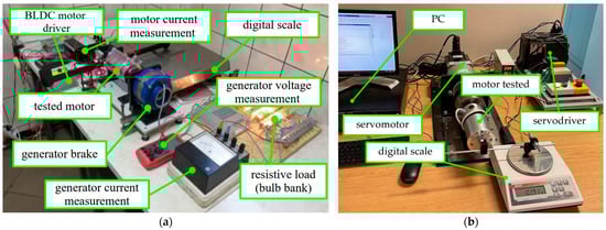
Figure 1.
Laboratory test benches used for motor investigation: (a) classical setup with generator-type brake and resistive load for measuring speed, torque, current, and efficiency []; (b) automated measurement stand dedicated to cogging torque determination, equipped with a servomotor and servodriver controlled by a PC and a digital scale for precise torque evaluation of the tested motor [].
2.5. Data Processing and Comparison
Efficiency η was calculated as the ratio of mechanical power (the product of measured torque and angular velocity) to electrical power consumed from the power supply.
To facilitate comparison of the three designs:
- Efficiency was determined at a constant torque of 1.4 N·m,
- Efficiency was evaluated at the rated points of each motor,
- The values of cogging torque and load torque reserve were analyzed.
3. Results and Discussion
The results of the design and experimental investigations of three electric motor configurations are presented and discussed in the following section.
3.1. PRMOa90-90 Ferrite Permanent Magnet Motor
The PRMOa90-90 commutator motor with permanent ferrite magnets is a classic solution used in mechanical barrier EEG drives. According to the manufacturer’s declaration, it is a machine with a rated power of 170 W, a supply voltage of 24 V, and a rated current of 10 A. The motor speed is 1100 rpm, at which it generates a torque of approximately 1.5 N·m. The use of this machine in the EEG drive has revealed limitations related to insufficient shaft torque for reliable operation. Overloading the motor to compensate for torque drops is not recommended, as it can lead to both demagnetisation and detachment of the magnets. Therefore, in practice, solutions are used that involve replacing this motor with more powerful units. The commonly used motor that replaces the PRMOa90-90 motor has a power of approx. 250 W and a rotational speed of 3000 rpm. The machine works with a planetary gear with a ratio of 1:3.7. This allows for a rated torque of 2.4 N·m at a speed of 810 rpm, improving the reliability of the entire drive system. However, the disadvantage of this concept is the increase in costs and the greater complexity of the design.
Figure 2 shows a cross-section of the PRMOa90-90 motor. Ferrite magnets shaped like ring segments are glued to the inside of the tubular housing. The machine armature has a lap winding distributed across 15 rotor slots. The design features and electromechanical parameters of the machine are presented in Table 1. The physical machine is shown in Figure 3.
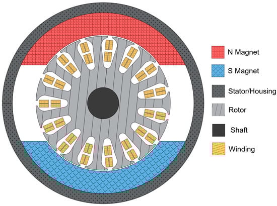
Figure 2.
Cross-section of PRMOa90-90 commutator DC motors.

Table 1.
PRMOa90-90 motor parameters.
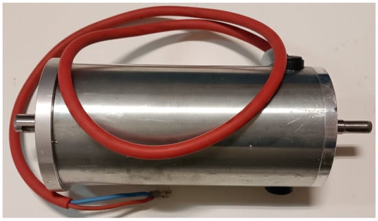
Figure 3.
Physical view of the PRMOa90-90 DC commutator motor used in the EEG barrier drive. The motor operates at 24 V and 170 W nominal power.
A FEM computational model was developed for the tested machine, based on which the magnetic flux distribution in the air gap and in the cross-section was determined, and the holding torque was calculated. The simulation tests show that the induction in the vicinity of the magnets is approximately 0.2 to 0.3 T, while in the vicinity of the grooves, it drops to only 0.1 to 0.15 T. The calculations of the cogging torque showed maximum values of 0.052 N·m, with a period of variation of approximately 12.2 electrical degrees. The small amplitude of the cogging torque is typical for designs with ferrite magnets because of the low energy density of these magnets. The results of the field simulation are presented in Figure 4 and Figure 5. Figure 6 shows the cogging torque of this machine.
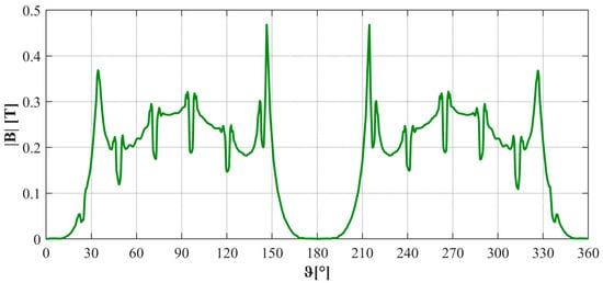
Figure 4.
Magnetic induction distribution in the air gap of the PRMOa90-90 motor.
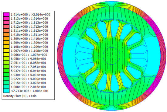
Figure 5.
Magnetic induction distribution in the cross-section of the PRMOa90-90 motor.
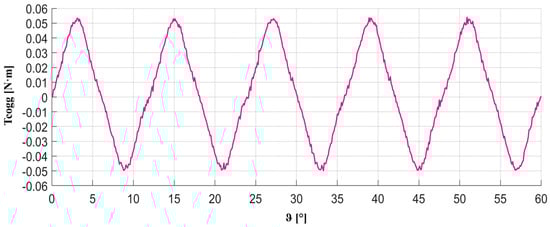
Figure 6.
PRMOa90-90 cogging torque.
Laboratory tests confirmed that the mechanical characteristics comply with the manufacturer’s specifications—at a rated speed of 1100 rpm, the motor develops a torque of approximately 1.4 N·m. The efficiency determined under rated load conditions is approximately 70%. The results of measurements carried out in laboratory conditions on the developed test benches are presented in Figure 7 and Figure 8. Figure 7 shows the electromechanical characteristics—rotational speed and armature current as a function of load torque. Figure 8 shows the efficiency of the machine across the entire range of tested loads. Due to the high risk of magnet detachment, overload tests simulating winter conditions were not performed for this motor design. The risk of permanent damage to the motor in this case is very high, and overloading the machine should be considered too dangerous to maintain the barrier’s fault-free operation.
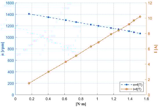
Figure 7.
Mechanical and current characteristics of the PRMOa90-90 motor. The left y-axis (blue dashed line, n = f(T)) shows the dependence of rotational speed n [rpm] on load torque T [N·m]. The right y-axis (red dash-dot line, I = f(T)) shows the dependence of armature current I [A] on load torque T.
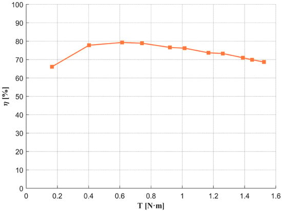
Figure 8.
Efficiency characteristic of the PRMOa90-90 motor.
3.2. Commutator Motor with Rectangular Neodymium Magnets
The authors of the study worked to develop a design that could serve as an alternative to the PRMOa90-90 motors currently used in EEG drives. The main objective was to create a low-speed motor with a torque that would allow it to operate without a gearbox in various weather conditions while at the same time having similar dimensions so that it could be easily adapted to existing barrier drives.
It is a commutator motor excited by N38 neodymium magnets. The use of sintered magnets allows for a significant increase in energy density and, consequently, the value of flux in the air gap []. In order to minimize production costs, the machine poles have been divided into segments made of rectangular magnets. The formation of neodymium magnets into arc-shaped elements is costly, while rectangular magnets are mass produced and significantly cheaper.
The magnets are placed in special slots in the packaged stator, which ensures their stable mounting and eliminates the risk of them coming loose during operation. An additional advantage of this solution is its simplicity of assembly. The cross-section of the motor is shown in Figure 9. The parameters of the machine developed are summarized in Table 2, while a view of the prototype is shown in Figure 10.
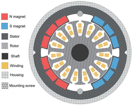
Figure 9.
Cross-section of commutator motors with rectangular neodymium magnets.
Table 2.
Structural parameters of the proprietary commutator motor with rectangular NdFeB magnets.
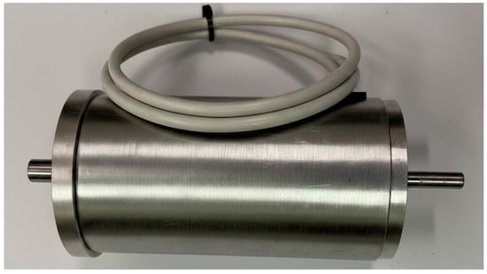
Figure 10.
Built prototype of a motor with rectangular neodymium (N38) magnets.
A detailed analysis of the proposed design, including the impact of magnetic circuit modifications on operating parameters, showed significant advantages over the motor used in the EEG drive []. The key issue for high energy density machines was to limit electromagnetic torque ripple and reduce vibrations associated with cogging torque. The field tests carried out allowed for the design of a structure in which the cogging torque did not exceed 0.04 N·m, which should be considered an acceptable level from the point of view of drive operation. Figure 11, Figure 12 and Figure 13 show selected results of FEM analyses, including the induction distribution in the gap, cross-section, and cogging torque.
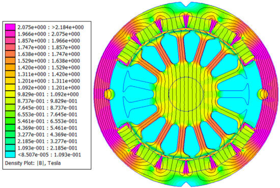
Figure 11.
Magnetic induction distribution in the cross-section of a commutator motor with rectangular neodymium (N38) magnets.
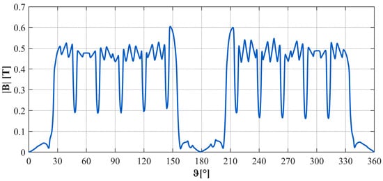
Figure 12.
Magnetic induction distribution in the air gap of a commutator motor with rectangular neodymium (N38) magnets.
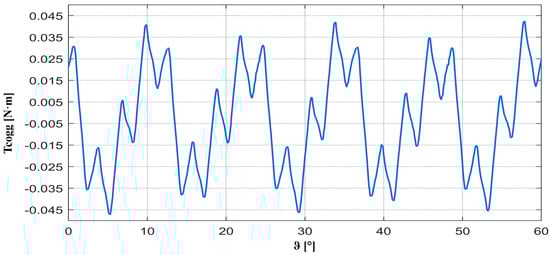
Figure 13.
Cogging torque of the commutator motor with rectangular neodymium (N38) magnets.
It is worth noting that despite higher induction in the gap, this machine has a significantly reduced starting torque compared to the classic motors presented in the previous subsection—the amplitude is 25% lower for the same period of variability. This is primarily due to the fact that the length of the machine has been significantly reduced—by 1/3. This translates into lower useful torque vibrations on the machine shaft, which is particularly important for the smooth operation of the barrier drive—not only does it reduce noise, but it also limits vibrations, which is particularly important in the case of a relatively long barrier arm. The results of laboratory tests are presented in Figure 14 (mechanical and current characteristic) and Figure 15 (efficiency characteristic). Due to the machine’s design—magnets placed in special slots in the packaged stator—it was possible to safely conduct overload tests. The purpose of these tests was to examine whether the machine is capable of generating sufficient torque to open and close the barrier smoothly in critical weather conditions (i.e., icing, snow on the barrier arm). The risk of demagnetization of the magnets in this machine was assessed as not particularly high. The motor operates intermittently—opening the barrier takes several dozen seconds, followed by a significant pause. Especially in winter conditions, where there is a potential need to overload the machine, the risk of overheating is minimal. In addition, classic N38 magnets can be replaced with N38SH or N38EH magnets with increased thermal resistance. Placing special magnets in slots also reduces the risk of mechanical damage, vibration, or increased corrosion due to damage to the protective coating, thus limiting the mechanical causes of magnet damage in this case as well.
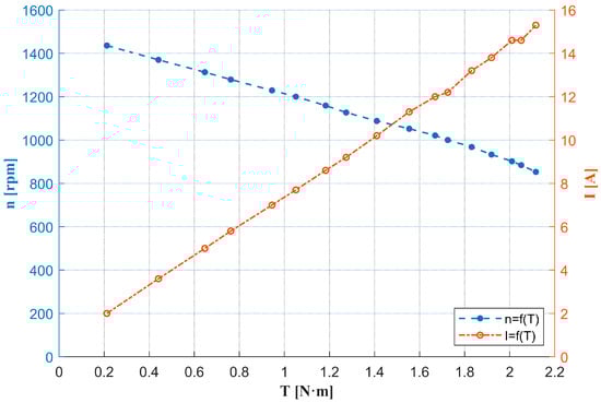
Figure 14.
Mechanical and current characteristics of the commutator motor with rectangular neodymium (N38) magnets motor. The left y-axis (blue dashed line, n = f(T)) shows the dependence of rotational speed n [rpm] on load torque T [N·m]. The right y-axis (red dash-dot line, I = f(T)) shows the dependence of armature current I [A] on load torque T.
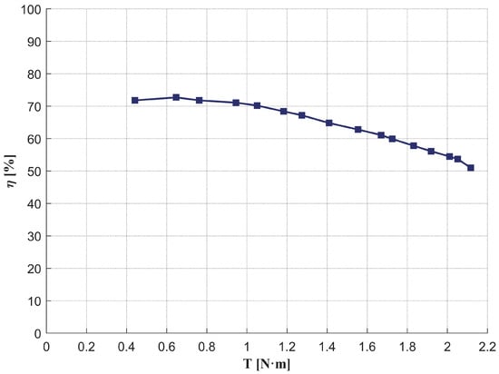
Figure 15.
Efficiency characteristic of the commutator motor with rectangular neodymium magnets motor.
3.3. Brushless DC (BLDC) Motor
The second alternative to the classic PRMOa90-90 motor proposed by the authors is a brushless DC motor (BLDC), whose cross-section is shown in Figure 16. The machine parameters are presented in Table 3. This design uses N38 neodymium magnets, arranged alternately around the rotor circumference. The windings are located in the stator, which allows for more efficient heat dissipation and the complete elimination of brushes and commutators—the components most susceptible to wear in classic commutator machines [,]. However, a BLDC motor requires an electronic commutation system. Most often, such commutation is performed by a microprocessor system that implements an appropriate control strategy—minimizing commutation losses and ensuring stable torque generation. In a classic sensor-based BLDC motor controller system, the position of the rotor must be known. This information is usually obtained from Hall sensors located inside the machine. In the presented motor, for design reasons and the need to use a brake in the counter-rotating part of the shaft, three slot optoisolators were used to determine the position of the rotor—Figure 17. The absence of friction elements in a BLDC motor, such as brushes and commutators, not only contributes to its maintenance-free operation (the service life of the machine is essentially determined by the durability of the bearings), but also to its efficiency—the absence of friction in the commutator results in lower mechanical losses.
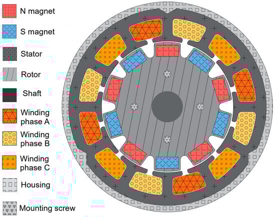
Figure 16.
Cross-section of the proprietary BLDC motor.
Table 3.
Structural parameters of the proprietary BLDC motor prototype.
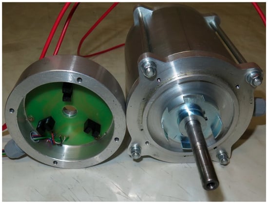
Figure 17.
A prototype of a proprietary BLDC motor with a rotor position detection system has been developed.
The BLDC motor was designed for parameters corresponding to the EEG-3 barrier drive: rated power 170 W, 24 VDC supply voltage, rotation speed 1000 rpm and rated torque 1.5 N·m. The magnetic system includes a stator with 12 slots and a ten-pole rotor, which reduces the cogging torque. Figure 18 shows the BLDC motor control system proposed by the authors for the EEG-3 drive, based on a microcontroller. The figure shows the control logic concepts based on logic gates and an electronic board that is a prototype of the device with implementation on a microcontroller. Figure 19, Figure 20 and Figure 21 present the FEM simulation for this machine, whereas Figure 22 and Figure 23 show the laboratory test results. The level-crossing drive equipped with the proprietary BLDC motor is shown in Figure 24.
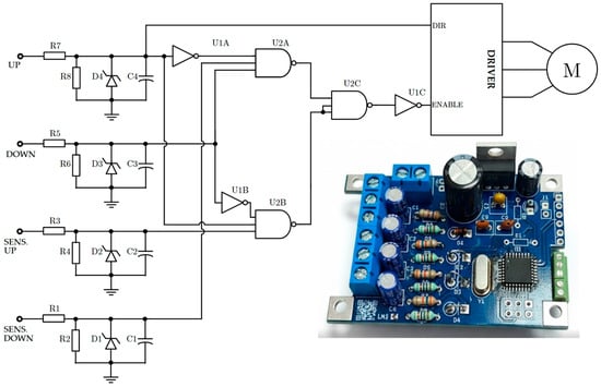
Figure 18.
Simplified conceptual diagram of the BLDC motor control system in the EEG-3 drive, together with the physical implementation of the system on a microprocessor.
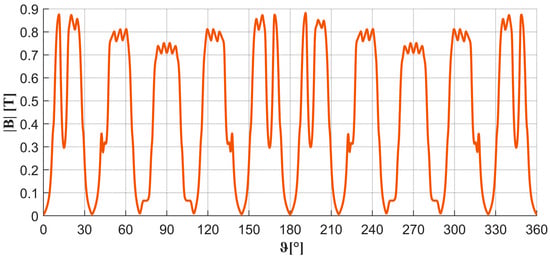
Figure 19.
Magnetic induction distribution in the air gap of a proprietary BLDC motor.
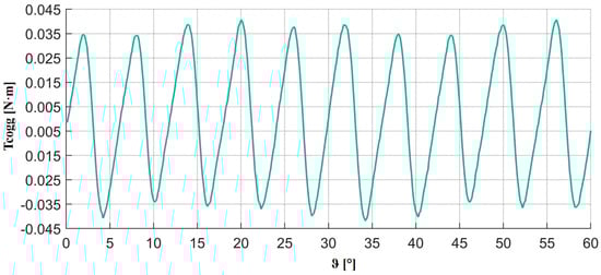
Figure 20.
Cogging torque of the proprietary BLDC motor.
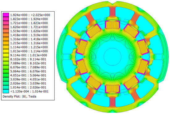
Figure 21.
Magnetic induction distribution in the cross-section of the author’s BLDC motor.
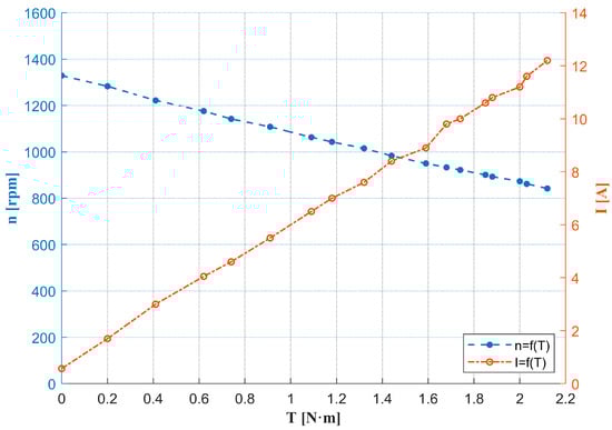
Figure 22.
Mechanical and current characteristics of the BLDC motor. The left y-axis (blue dashed line, n = f(T)) shows the dependence of rotational speed n [rpm] on load torque T [N·m]. The right y-axis (red dash-dot line, I = f(T)) shows the dependence of armature current I [A] on torque T.
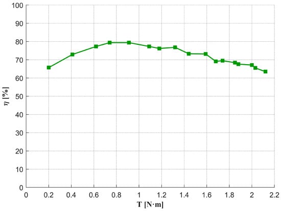
Figure 23.
Efficiency characteristic of the BLDC motor.
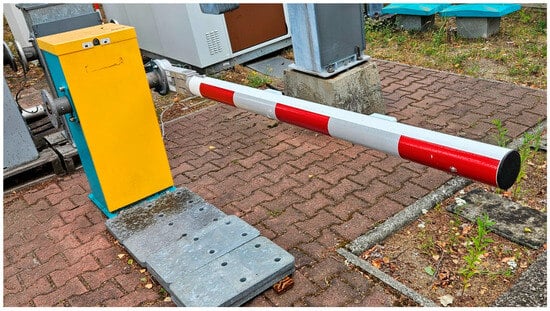
Figure 24.
EEG-3 drive with proprietary BLDC motor during field testing.
As shown in Figure 20, the appropriate selection of the ratio of the number of grooves to the machine poles (based on the authors’ previous design experience) allowed for an even greater reduction in the starting torque. It is worth noting that the frequency of this torque variation is twice as high. Similar to the machine described in Section 3.2, the tested BLDC motor was subjected to overload tests simulating operation in field conditions. As can be seen in Figure 22, the tested machine generates a torque of 2.2 N·m (at a current of 12A), which is sufficient for reliable operation in icy conditions. The field tests shown in Figure 24 were also conducted in various environmental conditions.
4. Discussion
The conducted research enabled a direct comparison of the key parameters of the three investigated motor designs [,,]. These include the classic PRMOa90-90 ferrite motor, the proprietary commutator motor with rectangular N38 magnets, and the proprietary BLDC motor.
Table 4 presents the key parameters and design features of the three motors tested. The data provided allows for a preliminary comparison of operational capabilities, maintenance costs, and design requirements.
Table 4.
General comparison of the motors investigated.
To objectively compare the efficiency of the all machines, their efficiency was determined at a working point corresponding to a torque of 1.4 N·m—equal to the nominal torque of the PRMOa90-90 motor. The results are presented in Table 5.
Table 5.
Efficiency of the commutator motors at torque of 1.4 N·m.
The comparison shows that at the same load, the ferrite-excited commutator motor achieves approximately 7% higher efficiency than the N38 magnet design. However, the latter compensates for this difference with a significantly larger torque reserve, which is crucial during operation under increased mechanical load. Table 6 shows the parameters and efficiencies of the motors tested at operating points corresponding to their design (rated) rotational speeds, where they can develop their characteristic operating parameters. The BLDC motor shows the highest efficiency in this comparison.
Table 6.
Efficiency of the investigated motors at rated operating points.
The efficiencies reported in Table 5 and Table 6 for the BLDC motor include the losses of the electronic commutation controller. Therefore, the actual mechanical efficiency of the motor is slightly higher. Considering the measured current and the on-resistance of the IRFZ44 MOSFETs (Vishay Intertechnology, Malvern, PA, USA), the conduction losses of the inverter can be estimated as approximately 2RDS(on)I2. Depending on the operating point, this corresponds to 3–10 W of additional losses, increasing the true motor efficiency by roughly 1–3 percentage points.
Although BLDC motors have higher initial costs due to the use of neodymium magnets and electronic controllers, these costs are offset by minimal maintenance requirements. In contrast, commutator machines require periodic brush replacement, commutator cleaning, and removal of carbon dust.
A generalized life-cycle cost cannot be estimated due to differing operational profiles of railway crossings, but the trends shown in Table 4 clearly indicate that the BLDC motor offers the lowest long-term maintenance burden.
An in-depth analysis of the impact of changes in key design parameters for a motor with rectangular magnets is presented in Dr. Strączyński’s doctoral dissertation []. It should be emphasized here that the research was conducted on prototypes of machines built by the authors. In general, satisfactory convergence of simulation results with actual measurements was achieved, but the impact of part manufacturing accuracy and mechanical tolerance is one of the areas planned by the authors for further research.
5. Conclusions
When selecting a drive for railway barriers, not only are the energy parameters important, but also all operating conditions [,]. The operating cycle of a barrier for different crossings is different and varies in terms of the number of activations per day. The operating environment of the motor indicates that high efficiency is not a decisive criterion. The costs of modifying existing equipment and the possibility of long-term operation of these are much more important. The original motor designs presented have different advantages and limitations profiles.
Maintenance services are well trained in the maintenance of machines with mechanical commutators. Modernisation of existing drives by replacing the motors with the proposed permanent magnet machine does not require any changes to the maintenance schedule. The new motor (PMDC and BLDC) designs are excited by neodymium permanent magnets. Sintered neodymium magnets have an energy density up to ten times higher than that of ferrite magnets. As a result, these machines not only feature reduced overall dimensions (approximately one-third shorter in length) but also, due to the higher magnetic flux density in the air gap, they generate higher torque at lower rotational speeds. The proprietary motor with rectangular N38 magnets has greater torque and can operate without a gearbox, reducing the number of moving parts. Although its efficiency is about 6% lower than that of the PRMOa90-90 at the normal operating point, it provides a significantly higher torque reserve (over 50%) and can be implemented in existing drives without major mechanical modifications.
The BLDC motor proposed by the authors seems to be a particularly attractive solution in new investments, especially where maximum reliability long-term maintenance-free operation are priorities. It achieves the highest efficiency (75% at nominal operating point) and is largely maintenance-free, but requires the use of an electronic commutation system with rotor position sensors and a power controller. This increases the initial cost and introduces greater system complexity compared to classic designs. However, the LCC analysis confirms the lowest total cost of ownership of the BLDC motor due to its maintenance-free operation. It is worth noting that the hooking moment for the newly developed machines has been reduced by 25%—mainly due to the reduction in the machine’s dimensions.
In summary, the selection of the optimal drive should be made individually for each crossing of the railroad, taking into account its actual operating intensity, technical conditions, and available maintenance resources. However, it is worth noting that the solutions proposed by the authors, due to their significant torque reserve, have a considerable impact on improving railway traffic safety and the reliability of barrier drive operation [,]. The results presented in this study demonstrate that the proposed motor designs can be directly applied to modernized railway barrier drives, offering improved reliability, higher torque reserve in winter conditions, and reduced long-term maintenance costs, which is of clear practical relevance to railway infrastructure operators.
Author Contributions
Conceptualization: Z.G.; Methodology P.S. and B.W.; Software, validation: P.S. and K.S., Formal analysis, investigation, resources: P.S., Z.G. and S.R.; Editing, S.R. and K.S.; Visualization: P.S. and B.W., Supervision: Z.G.; Project administration: P.S. and Z.G.; Funding acquisition: S.R. and K.S. All authors have read and agreed to the published version of the manuscript.
Funding
This research received no external funding.
Data Availability Statement
Most relevant data are included in the article. Additional data are not publicly available but can be obtained from the corresponding author upon request.
Conflicts of Interest
The authors declare no conflicts of interest.
References
- PKP Polskie Linie Kolejowe S.A. Wymagania na Systemy Zabezpieczenia Ruchu na Przejazdach Kolejowo—Drogowych i Przejściach Ie-119; PKP PLK: Warszawa, Poland, 2019. [Google Scholar]
- PKP Polskie Linie Kolejowe S.A. Instrukcja Ir-7—Przejazdy Kolejowo-Drogowe; PKP PLK: Warszawa, Poland, 2019. [Google Scholar]
- EN 50126-1:2017; Railway Applications—The Specification and Demonstration of Reliability, Availability, Maintainability and Safety (RAMS)—Part 1: Generic RAMS Process. CENELEC: Brussels, Belgium, 2017.
- International Union of Railways UIC. Leaflet 761: Addendum: Safety Measures on Lines Operated from 120 to 200 Km/h; UIC: Chicago, IL, USA, 2005. [Google Scholar]
- International Union of Railways UIC. Leaflet 761: Guidance on the Automatic Operation of Level Crossings; UIC: Chicago, IL, USA, 2004. [Google Scholar]
- Di Graziano, A.; Marchetta, V. Application of a Quantitative Risk-Based Decision Tool for Local Railway Level Crossing Management. Appl. Sci. 2024, 14, 8630. [Google Scholar] [CrossRef]
- Zawodny, M.; Kruszyna, M.; Szczepanek, W.K.; Korzeń, M. A New Form of Train Detection as a Solution to Improve Level Crossing Closing Time. Sensors 2023, 23, 6619. [Google Scholar] [CrossRef] [PubMed]
- Blagojević, A.; Kasalica, S.; Stević, Ž.; Tričković, G.; Pavelkić, V. Evaluation of Safety Degree at Railway Crossings in Order to Achieve Sustainable Traffic Management: A Novel Integrated Fuzzy MCDM Model. Sustainability 2021, 13, 832. [Google Scholar] [CrossRef]
- Anagnostopoulos, A. Assessing Safety and Infrastructure Design at Railway Level Crossings Through Microsimulation Analysis. Future Transp. 2025, 5, 24. [Google Scholar] [CrossRef]
- Pamuła, T.; Pamuła, W. Detection of Safe Passage for Trains at Rail Level Crossings Using Deep Learning. Sensors 2021, 21, 6281. [Google Scholar] [CrossRef] [PubMed]
- Kornaszewski, M.; Nowak, A. Analiza techniczna napędów rogatkowych stosowanych na przejazdach kolejowo-drogowych w Polsce. Autobusy Tech. Eksploat. Syst. Transp. 2017, 18, 974–977. [Google Scholar]
- WAMEL Silniki Elektryczne Sp. z o.o. Silnik Prądu Stałego z Magnesami Trwałymi. Typ PRMOa 90-90. Karta Katalogowa nr 393. WAMEL Silniki Elektryczne: Warszawa, Poland, 2019. Available online: https://www.wamel.com.pl/wp-content/uploads/2019/07/karta-katalogowa-PRMOa-90-90-393.pdf (accessed on 4 September 2025).
- Suriano-Sánchez, S.I.; Ponce-Silva, M.; Olivares-Peregrino, V.H.; De León-Aldaco, S.E. A Review of Torque Ripple Reduction Design Methods for Radial Flux PM Motors. Eng 2022, 3, 646–661. [Google Scholar] [CrossRef]
- Marcos-Andrade, D.; Beltran-Carbajal, F.; Castelan-Perez, A.; Rivas-Cambero, I.; Hernández, J.C. Online Algebraic Estimation of Parameters and Disturbances in Brushless DC Motors. Machines 2025, 13, 16. [Google Scholar] [CrossRef]
- Abouseda, A.I.; Doruk, R.O.; Amini, A. Parameter Identification and Speed Control of a Small-Scale BLDC Motor: Experimental Validation and Real-Time PI Control with Low-Pass Filtering. Machines 2025, 13, 656. [Google Scholar] [CrossRef]
- Goryca, Z.; Straczynski, P.; Cygon, P. Brushless DC Motor and Control System for EEG-3 Crossing Barier Drive. Autom. Elektr. Zakloc. 2025, 16, 42–50. [Google Scholar] [CrossRef]
- Kyosan Electric Mfg. Co. Ltd. Napęd Rogatkowy. Rogatki z Udoskonalonym Mocowaniem. 2018. Available online: https://kyosan.com.pl/wp-content/uploads/2023/09/Leaflet_Gate_Mechanism_PL.pdf (accessed on 4 September 2025).
- Strączyński, P.; Różowicz, S.; Baran, K. Automated Laboratory Stand for Determining the Cogging Torque of a Small Permanent Magnet Electric Machine Using the MATLAB Environment. Energies 2025, 18, 1047. [Google Scholar] [CrossRef]
- Strączyński, P. Analiza Wpływu Wybranych Zmian Obwodu Magnetycznego Na Parametry Silnika Komutatorowego z Magnesami Trwałymi. Ph.D. Thesis, Kielce University of Technology, Kielce, Poland, 2024. [Google Scholar]
- Gieras, J.F. Electrical Machines; CRC Press: Boca Raton, FL, USA, 2020; ISBN 978-0-367-73694-1. [Google Scholar]
- Gieras, J.F.; Shen, J.-X. Modern Permanent Magnet Electric Machines: Theory and Control; CRC Press: Boca Raton, FL, USA, 2022; ISBN 978-1-000-77700-0. [Google Scholar]
- Hanselman, D. Brushless Permanent Magnet Motor Design; Magna Physics Publishing: Lebanon, OH, USA, 2006; ISBN 1-881855-15-5. [Google Scholar]
Disclaimer/Publisher’s Note: The statements, opinions and data contained in all publications are solely those of the individual author(s) and contributor(s) and not of MDPI and/or the editor(s). MDPI and/or the editor(s) disclaim responsibility for any injury to people or property resulting from any ideas, methods, instructions or products referred to in the content. |
© 2025 by the authors. Licensee MDPI, Basel, Switzerland. This article is an open access article distributed under the terms and conditions of the Creative Commons Attribution (CC BY) license (https://creativecommons.org/licenses/by/4.0/).