Abstract
The authors of this paper highlight the creation of an experimental system for the implementation and testing of active low-voltage electronic power filters of the parallel type, with applicability in a wide range of electrical parameters. In this paper, the authors present the results obtained on an experimental test bench for power quality purposes. The experimental test bench is one of the results of a technology transfer project. One of the specific objectives of the project was to carry out industrial research and experimental development activities in order to develop a competitive, technical and economic solution for an intelligent power system, Active Power Filter (APF). Thus, this paper presents the experimental test bench for the design, implementation and testing of algorithms for current harmonics mitigation. The conceptual theoretical frame bases of both direct and indirect control have been presented by the authors. As a case study, both the simulation and experimental results of the indirect control strategy implemented on the test bench are provided. The indirect control method is chosen due to simplicity, no complex calculus requirements, and the use of a minimum number of transducers. By features comparison with modern control strategies, this study underlines the supremacy of the indirect control in active harmonics control.
1. Introduction
In the last years, with power electronics development, the amount of common-use equipment to improve the living or working conditions has increased considerably: digital computing systems, digital televisions, intelligent lighting systems, modern refrigerators, air conditioners, etc. All the above-mentioned electrical consumers, mainly nonlinear, can be grouped as follows:
- -
- Nonlinear loads of the rectifier type with resistive-capacitive load, where the capacitive component is constant and the resistive component is given by the energy consumption of the device. As typical examples, most portable or “desktop” personal computers, monitors, televisions, printers, compact fluorescent lamps, power LED lamps, switching power supplies for various low-power devices could be mentioned.
- -
- RLC-type loads, which, due to reactive components (inductor/capacitor) directly connected to the alternating current grid, vehiculate reactive energy between the load and grid power supply. As typical examples, heat pumps with compressor motor (refrigerator, air conditioners, water dispensers), fluorescent lamps with inductive choke, cheap lighting solutions based on low-power LEDs (current limitation is done using a series capacitors) could be mentioned.
- -
- Electronic circuits powered by a power supply transformer.
- -
- Power regulation circuits by adjusting the phase angle of a triac connected in series with the respective equipment (incandescent bulbs, electrical resistors, etc.).
If the problem of the phase shift between the consumed current and the supply voltage can be solved relatively easily with the help of passive filters made up of capacitors, resistors and coils, the problem generated by rectifier bridge and RC load consumers is important because, regardless of the active power consumed, energy is absorbed from the electrical grid in the form of current pulses, lasting 1–3 ms, synchronized with the maximum instantaneous value of the grid voltage. The simultaneous use of many such consumers leads to the appearance of specific problems in the electricity distribution grid:
- -
- Distortion of the grid voltage for consumers located at a great distance from the transformation point, due to the impedance of the electrical grid.
- -
- Increased power losses in electrical transformers placed into the transformer stations.
- -
- Imbalance of the three-phase electrical network due to unbalanced consumption in the 3 phases.
Passive RLC filters in series/parallel with the polluting load are one of the pioneer solutions, widely used in the past, so that the polluting components of the load current do not flow into the energy distribution grid. With the increase in the number of rectifier bridges with resistive-capacitive load type consumers, passive filters become difficult to design and use. The use of active power filters to improve the quality parameters of electricity is the current solution that allows the correct and efficient compensation of the nonlinearities of one or more polluting electrical loads. For the same power level, the cost of an active filter varies less with its hardware structure and more with the complexity of the operating algorithm. The better the active filter’s ability to improve grid signals, the more complex and expensive the filter becomes.
For three-phase systems, shunt active power filters are usually used, and the traditional control laws are based on the:
- -
- Instantaneous power theory [].
- -
- Pollutant component extraction method [].
Ssynchronous reference system method [].
In [,,] a general presentation of the current control solutions for three-phase active power filters is made, from which the three classical methods mentioned above, are still intensively used due to the very good performances they offer. A more detailed comparison can be found in []. Different control structures from those already mentioned can be found in [,,,,,,,]. Each solution presents at least one advantage over the classical solutions (simpler hardware structure, use of a lower voltage on the filter’s DC voltage line, elimination of voltage or current transducers, operation without a PLL circuit, control law with a minimum of mathematical operations, etc.). In single-phase systems, reference can be obtained from the frequency analysis of the nonlinear load current, through adaptive, genetic algorithms [,] or through indirect methods.
The shunt active power filter has the role of imposing an electric current of a certain shape and amplitude at the output. In order to use the power semiconductor devices efficiently, they are used in the switching mode and not in the linear mode. The power losses on the filter components are minimized, even if the spectrum of the harmonics compensated by the filter is significantly reduced below the value of the inverter switching frequency. Typically, the control signals for static switches are generated either by means of hysteresis regulators or by PWM modulators preceded by a regulator. For example, [] presents simulation results for three control methods applied to the same hardware structure of an shunt active filter: the p–q theory (instantaneous active and reactive powers) adapted to the single-phase system; the DC side voltage control method, found in other references, [,] as the indirect control method, which obtains useful information from the voltage variation at the terminals of the active filter capacitor; the nonlinear load average power method, which calculates the load average power by filtering the result of multiplying the instantaneous values of voltage and current. Research in this field [,,,,], etc., does not converge towards a unique solution, valid for any energy system and any disturbance, but rather offer optimal solutions for each particular system. It is not a matter of the impossibility of creating such an active power filter, but the complexity and cost of implementation. The success of the solution comes from the efficiency of the solution (from as many points of view as possible). The active power filters should meet the approved power quality standards [,,].
Recently, despite the above-mentioned traditional control methods, new approaches of shunt active power filter control have been proposed by researchers. Due to the varying power system parameters, techniques based on artificial intelligence have been proposed [,,]. The learning features and prediction capacity are the main advantages of integrating intelligent control techniques into large applications, solving the power quality issues [,,,,,,].
The contributions of this paper are as follows:
- The authors of this paper highlight the creation of an experimental system for the implementation and testing active low-voltage electronic power filters of the parallel type, with applicability in a wide range of electrical parameters.
- The system is characterized by a versatile, reconfigurable connection. Both the indirect and direct control strategies intelligently use the components and control loops of the classic active filter.
- Since the position of the voltage and current transducers can vary depending on the control strategy of the active filter, the system proposed [,] contains reconfigurable connectivity elements to reallocate the transducers to the required position. Thus, direct control systems of active power filters can be implemented without changing the position of the transducers in the experimental system. On the experimental test bench, the voltage and current transducer block consists of three voltage transducers and six current transducers, connected between the grid, the polluting consumer and the voltage inverter. Their position and the measurement direction can be modified without affecting the power circuit of the experimental stand.
This paper follows the methodology of modeling, sizing, simulation and experimental validation of an experimental three-phase active power filter. The choice of an efficient structure of the active filter starts with the analysis of the nonlinear consumers that need to be compensated. The adequate hardware structure of the active harmonic power filter is then chosen and sized according to the power and nonlinearities of the targeted nonlinear consumers. The control method is chosen to allow the correct operation of the active power filter with a minimum number of transducers and without complex mathematical processing.
This paper contains seven sections. In the Introduction section, the power quality improvement methods are highlighted. The Materials and Methods section enumerates the control strategies implemented on the experimental testbench, classified in direct and indirect control methods. The concept of the harmonic free power system is described in the third section. Implementation of the active power filter indirect control is provided in the fourth section. The obtained numerical simulation results and the experimental results are provided in the fifth and sixth sections. At the same time, the parameters of the power system are provided in the sixth section. The last section offers the main conclusions of this work.
2. Control Strategies
The purpose of the experimental test bench is to develop, implement and test different harmonics mitigation strategies for technological transfer. They are divided into direct control and indirect control. Direct control measures the nonlinear load current. The SAPF current references are based on the extraction of the polluting load current components.
The control law practically dictates the principle by which the active filter operates, which analogue signals are acquired from the system, how the reference quantities for the control loops are obtained, as well as the specifics of these loops. The active power filters have been developed mainly to improve the power quality in three-phase grids. In the case of a shunt filter, the most important problem is to calculate the reference for the current injected into the grid, so that the load nonlinearities are compensated. Solving the problem in the time domain involves the use of control methods such as instantaneous powers, principle of maximum, synchronous algorithm, etc. (Table 1).

Table 1.
Implementation of direct and indirect control algorithms for the Active Power Filter (FAP-0L) [,,,,,,,,,,].
The experimental system is realized by interconnecting programmable electronic components and equipment with the aim of reducing current harmonics and compensating reactive power in electrical power supply grids. The FAP-0L experimental system allows testing filters for any configuration of the electrical grid up to 230 V alternating voltage, for both 50 Hz and 60 Hz frequencies, but also for any algorithm presented in Table 1. The limits of the described system are alternating voltage 0~330 VL-N/0~570 VL-L, voltage frequency 30~100 Hz, maximum power: 30 kVA. For the FAP-0L experimental system, the implemented control strategy unifies indirect control (8) with all control algorithms specific to industrial prototypes (1–7), without the need to change their hardware configuration (Table 1) [,,,,,,,,,,].
In Figure 1, the used principle of the power grid depolluting solution is depicted. According to below-delivered mathematical equations, the shunt active power filter (SAPF) is necessary. The active power filter should be connected by Point of Common Coupling (PCC). The industrial electric oven supplied by a nonlinear power converter was considered in this study [,]. The active power current references are provided both for the direct and indirect control techniques. The indirect control has been implemented in the Matlab–Simulink R2021b environment. Both the steady state and dynamic regimes are provided. The results obtained from the experimental test bench are included.
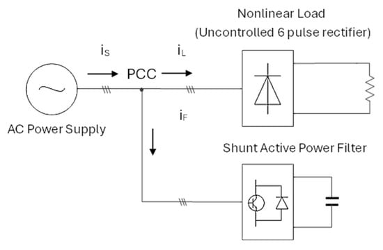
Figure 1.
The applied principle of the grid depolluting solution.
3. Concept of the Harmonic Free Power System
In general form, for one phase, the instantaneous nonlinear load current is as follows:
where is the fundamental active component of the load current, is the fundamental reactive component of the load current, and are the k harmonic components of the load current.
In order to obtain a depolluted power supply grid, the following load components
should be vanished (compensated) by the other equipment. The compensation should be provided by inserting the same negative quantity into the load connection point; that is, in parallel with load. This task is performed by the active power filter. Because a negative sign should be obtained, the active power filter is connected in parallel with the load. This equipment is referred to as the shunt active power filter (Figure 1). The classic interconnection structure of the electrical grid, the nonlinear load and the active power filter are represented in the following figure, where the voltage and current transducers have not been represented because both their position and type are dictated by the control law/operating principle of the active filter.
The mathematical formulation is as follows:
By combining (3) with (1)
But from Figure 1, according to the Kirchhoff First Law, phase supply current
By combining Equation (5) with the Equation (4),
For any load type (general polluted load behaviour), the depolluted power supply should accomplish the fundamental Equation (5).
The phase supply current should be same with the fundamental active component of the load current. This task is performed by the shunt active power filter.
Assuming the sinusoidal power supply voltage, the significance of the fundamental Equation (5) is that the phase supply current is in phase with the power supply voltage and has the same sinusoidal form with the phase voltage, i.e., a unity power factor should be obtained.
3.1. SAPF Current Reference for the Direct Control Method
The direct control of SAPF supposes the reference generation of the active power filter by extraction of the polluting components of the load. This method should measure the load current directly to synthesize the compensation current.
By considering the sinusoidal power supply [,,,]:
the general form of the phase load current is divided into the fundamental component and the polluted load current component :
The same approach applies to the phase active filter current:
The related instantaneous power absorbed by the active power filter is as follows:
Analogue, the instantaneous power absorbed by the load:
The power balance of the entire system:
The condition for the depolluted power system are as follows:
From Equations (12) and (13), the depolluted power system should accomplish the following relation:
Taking into consideration the above deducted condition (14), using Equations (10) and (11), the result is:
or in the other form:
By using the instantaneous power conservation principle,
and integrating over a period of the power grid, T,
or in the other form:
Therefore, the fundamental power absorbed by the active power filter is the variation of the accumulated energy in the DC capacitor in the time T
On the other hand,
From the Equations (21) and (22), the fundamental current of the active filter can be deducted in the below mentioned form:
From Equations (14) and (16), by considering into Equation (9), result the final form of the active power filter current reference:
3.2. SAPF Current Reference for the Indirect Control
The obtained reference of the active power filter supposes the extraction of the polluting components of the load []. However, one convenient solution is proposed in this paper: the indirect control method.
The indirect control method of the active power filter supposes the delivering of the reference supply current that depends only on the active energy used by the nonlinear load. The indirect control method does not take into account the amount of reactive energy exchanged between the active filter and the nonlinear load, but the reactive energy of the load is compensated implicitly.
The active filter performs its function correctly if it:
- Ensures the circulation of instantaneous reactive power only between the nonlinear load and the active filter; the SAPF will not exchange active energy with the power grid.
- Injects all the necessary harmonics of the current to the nonlinear load; since these harmonics determine active energy consumption in the nonlinear consumer, it means that the SAPF will absorb from the grid the energy equivalent in the form of a sinusoidal current and in phase with the grid voltage.
The indirect control method is presented in Figure 2. The implementation of the active power filter involves the dimensioning and realization of a control structure consisting of two regulation loops: one for the “on-line” calculation of the power supply current amplitude, and one for imposing the corresponding amplitude and shape of the grid current. The proposed structure is depicted in Figure 2.
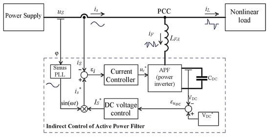
Figure 2.
Block diagram of the indirect control of the Active Power Filter [].
This intelligently uses the components and control loops of the classic active power filter, as follows:
- -
- A current loop that forces the current absorbed by the filter-polluting load assembly to the ideal shape and amplitude (sinusoidal curve and in phase with the voltage at the point of common connection, PCC).
- -
- A voltage loop maintains the energy stored in the active filter capacitor quasi-constant. Energy is calculated in such a way as to ensure the achievement of the largest amplitude necessary to be imposed for the current absorbed from the power supply.
- -
- The voltage inverter is used both to generate the current requested from the filter in order to meet the above condition, and as a PWM “boost” rectifier to maintain the capacitor charge at the operating voltage (about twice the peak value of the grid voltage). Both functions are controlled by a single PWM control.
By considering that the capacitor energy remains constant over a period of the phase voltage, the maximum value of the power supply current is determined.
Taking into account that the current regulator aims to regulate the total current absorbed from the grid, and that this current is desired to be sinusoidal and in phase with the grid voltage, it is required that the reference input of the current regulator be of the form:
= rms value of the power supply,
= the output of the DC voltage controller.
By choosing a proportional regulator with gain k for the current controller, the control equation of the active filter results as:
Because the fundamental components of the load and filter currents are found in the sinusoidal reference of the current regulator , the current reference becomes as follows:
in which:
For the steady state,
In other words, the pollutant component necessary for the nonlinear load is generated by the active filter itself.
It is necessary to add one regulator for vanishing the voltage regulation error (with output magnitude variation slow enough not to disturb the sinusoidal current curve, but fast enough not to allow complete discharge or overload of the capacitor in transient situations), and another regulator to control the current loop (Figure 2).
For the three-phase power system, the SAPF implementation is as in Figure 3.
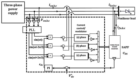
Figure 3.
Block diagram of the three-phase indirect Active Power Filter [].
The reference current of the active power filter:
In the other form [], the reference current for the a phase is as follows:
In Figure 4, the current references of the three-phase active power filter under indirect control are presented.
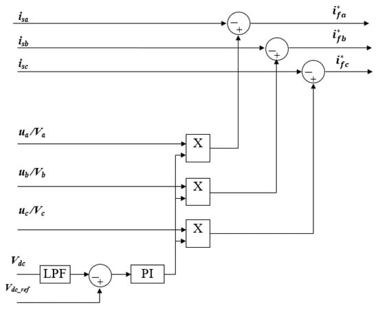
Figure 4.
Block diagram of the synthesized current references based on indirect control.
The current references of the indirect control method are delivered based on the measured power supply currents (Figure 4). The fundamental current reference of the SAPF is provided by the outer DC voltage loop (Figure 2).
The reference currents for the SAPF can be obtained based on Equation (29). Both the regulation role and the switching states references are provided by the current control/modulator (Figure 3) on each phase.
In Figure 4, the SAPF current references for the indirect control are shown. It could be noted that only voltage and current supply signals are used to provide the reference SAPF currents. Additionally, the DC voltage control delivers the amplitude of the reference currents, being multiplied by the sinusoidal three-phase system.
4. Implementation of the Active Power Filter Indirect Control
The entire power system consists of the three-phase grid power supply, the connected three-phase nonlinear load and the SAPF delivering throughout the PCC. In Figure 5, the implementation of the active power filter indirect control in Matlab–Simulink is shown. In order to underline the SAPF principle, adequate dashboards have been created. As can be seen, the load currents are non-sinusoidal. The ability of the SAPF control conduct to the adequate compensation currents generation to depollute the power supply by the higher current harmonics. Additionally, the dashboard with the power supply THD% current signals are provided.
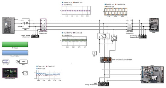
Figure 5.
Indirect control software implementation of the of compensation power system.
Figure 6 shows the sub-blocks components of the SAPF block (Figure 3). It consists of the power side block of the SAPF and the control side. The APF control block provides the references of the compensation currents, having as input the measured DC capacitor voltage. The SAPF block receives the three-phase reference currents. The SAPF is connected to the PCC through the L1, L2 and L3 power output lines.
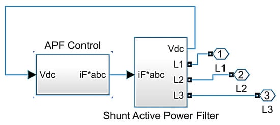
Figure 6.
SAPF Matlab R2021b software implementation.
In Figure 7, the APF control block (Figure 6) details are provided. Based on Figure 4, the SAPF current references are generated.
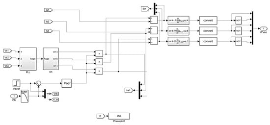
Figure 7.
The software implementation of APF control.
In Figure 8, the power structure of the SAPF software is implemented. It consists of the three-phase power bridge with the C1, C3 and C5 upper control signals, and appropriated inverting C4, C6 and C2 lower bridge signals. The DC voltage is measured from capacitor C.
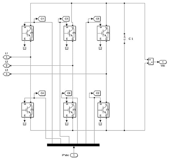
Figure 8.
The software implementation of SAPF power structure.
The indirect control strategy applied to the three-phase system contains the following loops:
- A PLL loop that generates sinusoidal signals of the same frequency and phase as the phase voltages of the grid.
- A Voltage regulation loop at the terminals of the voltage capacitor in the voltage inverter, with a PI (proportional-integral) type regulator, which imposes the amplitude of the reference current to be extracted from the grid.
- Three current internal loops, one for each phase, with a P (proportional) type regulator, which delivers the control pulses for the three-phase bridge of static switches.
5. Numerical Simulation Results
As a case study, the numerical simulation results of the indirect control of the active power filter are presented in this section. The control is in a cascaded manner (Figure 3) with the voltage control as the outer loop. The pre-charging phase starts at t = 0.05 s, when a 72 Vdc voltage is applied. In order to verify the performances of the voltage loop, one-step DC voltage is applied as a voltage reference (90 Vdc) after the pre-charging phase of the DC capacitor (). The Proportional-Integral voltage controller is used to reach the reference. Due to the integral contribution, the steady-state error is vanishing (Figure 9); that is, the actual DC voltage (red dotted line) is superimposed on the reference voltage (blue continuous line). It could be noted that no overshoot is presented.
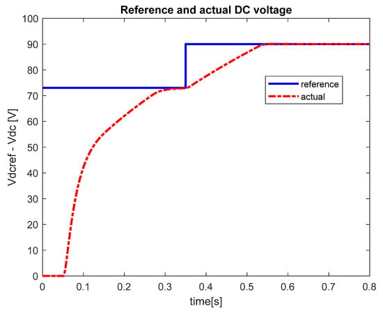
Figure 9.
The control performances of the DC voltage loop of the indirect control of the active power filter.
The performances of the indirect control of the active power filter are shown in Figure 10. As can be seen, the supply voltage is in phase with the supply current during normal operation of the active power filter. Moreover, the source current is sinusoidal, i.e., harmonic free. The source current transients during the pre-charge phase demonstrate a unity power factor operation (0.05 s < t < 0.35 s). At the same time, before active power filter connection, the nonlinear load current affects the source current (0 < t < 0.05 s).
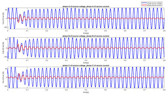
Figure 10.
The symmetrical three-phase grid voltage (blue) and the symmetrical three-phase grid currents (red).
The three-phase load currents are non-sinusoidal and presented in Figure 11.
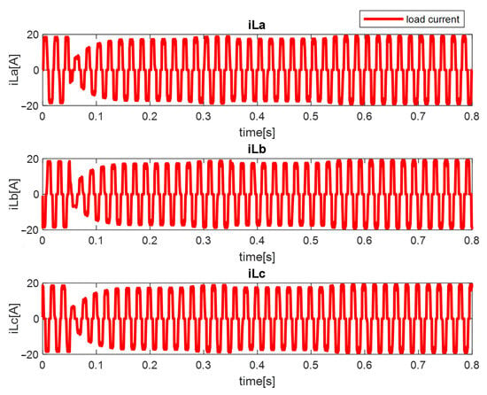
Figure 11.
The non-sinusoidal three-phase system of the load currents (iLa-load current of the phase a, iLb-load current of the phase b, iLc-load current of the phase c).
In Figure 12, the three-phase reference currents of the developed indirect control are shown.
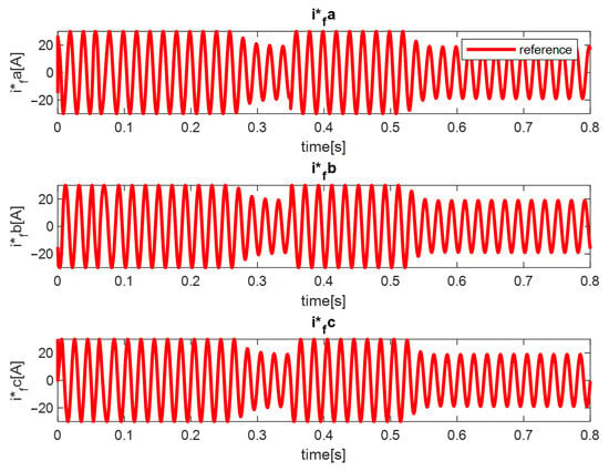
Figure 12.
The active power filter reference currents based on the indirect control (i*fa—active filter reference current of the phase a, i*fb—active filter reference current of the phase b, i*fc—active filter reference current of the phase c).
Based on the developed indirect control theory, the obtained reference currents are presented in Figure 12.
In Figure 13, the numerical simulation results of the obtained feedback active filter currents are presented.
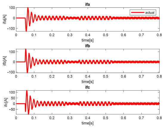
Figure 13.
The three phase system of the currents (ifa—active filter feedback current of the phase a, ifb—active filter feedback current of the phase b, ifc—active filter feedback current of the phase c).
In Figure 14, during the starting process, the detailed analysis of the supply current is taken into consideration. In Figure 14, the nonlinear flow current through the power supply (red marked signal) is due to the nonlinear load, the active power filter being disconnected.
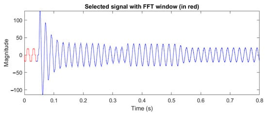
Figure 14.
The highlight (red marked signal) of the nonlinear flow current through the power supply.
The harmonic analysis reveals a distortion factor of 27.7% for the supply phase current (Figure 15).
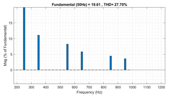
Figure 15.
The Fast Fourier Transform analysis of the above selected supply current.
In order to compare the supply current harmonic analysis in two cases—without active filter (Figure 15) and by means of active filter—a new selected window has been chosen (Figure 16). Starting with t = 0.7 s, two supply current cycles have been selected (red line signal with 0.04 s time interval for 50 Hz). The obtained THD of 3.28% (Figure 17) demonstrates a harmonic improvement for the supply current through the indirect control.
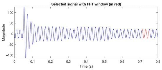
Figure 16.
Harmonic analysis of the supply current during indirect control of the active power filter action (red marked signal).
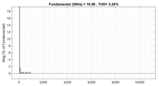
Figure 17.
The Fast Fourier Transform analysis of the supply current by means of the indirect control.
For suggestive comparison, the obtained simulation results could be converted into a graphical image (Figure 18). The obtained decrease value of 3.28% THD for the supply current demonstrates the efficacy of the proposed indirect control solution.
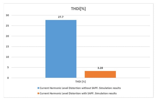
Figure 18.
The harmonic analysis of the supply current in two cases: without active power filter control (27.7%) and through the proposed indirect control of the active power filter.
6. Experimental Results
One of the results of the technology transfer project used in [,] was to obtain a functional experimental system for free power grid current harmonics. The purpose of the power system development was to implement a competitive technical and economic solution. In order to find the appropriate solution, several algorithms have been developed and implemented (Table 1). Due to the reduced number of transducers, indirect control proved to be a promising solution. In order to test the feasibility of the solutions, the electrical grid is emulated by using a three-phase programmable voltage source, both in terms of amplitude and frequency, as well as the waveform shapes of the output signals. The indirect control method intelligently uses the hardware components of the active power filter as well as the positioning of the transducers so that the processing calculus related to the control loops is minimal [,]. The experimental system for the implementation and testing of active three-phase power filters and parallel type is characterized by the fact that the voltage and current transducers have dual outputs, with two sensitivity ranges to optimally cover the range of interest of the measured quantities. Since the position of the voltage and current transducers can vary depending on the control strategy of the active power filter, the system proposed in [,] contains reconfigurable connectivity elements to reallocate the transducers to the required position. To demonstrate the feasibility of the proposed solution, this paper presents the experimental results obtained for a three-phase, symmetrical voltage supply system (55 Vac), which uses only the first sensitivity range, both for low voltages and loads. Moreover, it demonstrates the obtaining of a flexible experimental test bench, which facilitates the implementation of different control solutions, the necessary stage in the subsequent prototyping of the active power filter solutions. Furthermore, the paper focuses on both the presentation of the configured test bench and the experimental results obtained from it.
The indirect SAPF control was implemented on the cRIO-9039 FPGA-based platform (Figure 19). In the previous section, the simulation results of the proposed indirect control were presented. The real-time response of the harmonic filter is based on the FPGA-hardware based system. The entire control of the harmonic filter was implemented using the LabVIEW2017 myRIO Professional Development System. The hardware components of the test bench are based on [,], and explained as follows:
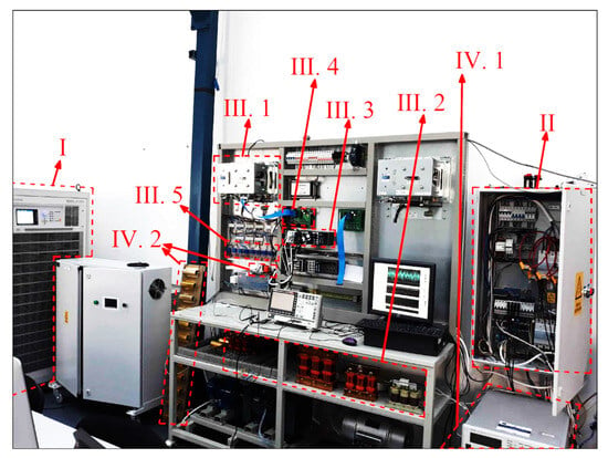
Figure 19.
The indirect control implementation on the SAPF experimental test bench.
- The CHROMA 61830 model was used as the adjustable three-phase power supply.
- The Point of Common Coupling (PCC) was designed to connect the power supply, load and active power filter.
- The harmonic power filter was composed of:
- the three-phase SEMIKRON power bridge (III.1);
- the inductive interface with the PCC (III.2);
- the numerical calculus equipment based on the cRIO-9039 FPGA platform from National Instruments (III.3); and
- the signal conditioning board (III.4) used to adapt and adjust the digital PWM control signals to SEMIKRON three-phase power bridge (III.1);
- the three-phase feedback signals from the voltage (LV-25P) and LA-55P current transducers (III.5),
- the nonlinear load (IV.1), a programmable three-phase load (CHROMA 63802, 8 kW/18 A/350 V); and
- the uncontrolled bridge rectifier (IV.2) [].
The voltage range of the adjustable three-phase power supply is [0, 400 V] ± 10%, the grid frequency range is [0, 63] Hz. The maximum phase current is 65 A, working in four quadrants, with the rated power of 30 kVA. The control and data acquisition platform (cRIO-9039) is based on the 1.91 GHz Intel Atom, Quad-Core Controller, 8-Slot, Kintex-7 325T FPGA, Real-Time. One disadvantage of the real time FPGA-based controller is the manual conversion from the floating-point operation to the fixed-point operation.
Both the remote and local monitoring signals are available. For the local signals monitoring (Figure 20), the FLUKE 437 Series II Power Quality and Energy Analyzer, 400 Hz (manufactured by Fluke Corporation, which is headquartered in Everett, WT, USA) was involved. For the remote signals monitoring (Figure 21), the DESKTOP-NHKC48L, 11th Gen Intel(R) Core ™ i3 @3Ghz, 8 GB installed RAM was used. However, the main function of the DESKTOP is to control the harmonic power filter, including start/stop function.
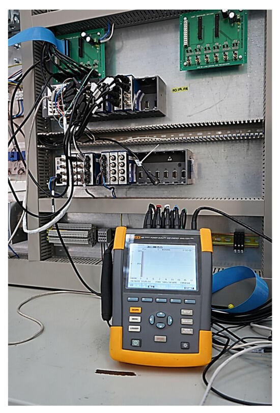
Figure 20.
The local monitoring system of the harmonic filter.
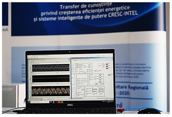
Figure 21.
DESKTOP for the remote control and monitoring of the harmonic power filter.
The numerical system type is formed by 64-bit operating subsystem, x64-based processor. The indirect control algorithm is developed on the above-mentioned DESKTOP. The implemented control is transferred to the compact RIO module for local execution. In order to deliver the control reference signals of the harmonic filter, the obtained sinusoidal signal from PLL (Figure 2) is multiplied by the output signal of the DC link controller (Figure 22).
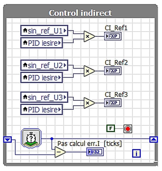
Figure 22.
FPGA implementation of the indirect control on the active power filter.
In order to control the enable (start/stop) function and the appropriate switching states for the upper power bridge of the harmonic compensator, the LabVIEW user interface was developed (Figure 23). The interface allows changing the algorithm type, between indirect (1T = CI) and direct current control (0F = FOB). Another function is to monitor the signals of interest in numerical form. An electrical oven of 5 kW is used as the load []. The oven is supplied by using a three-phase six-bridge pulse rectifier.
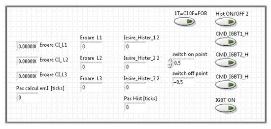
Figure 23.
The customized interface to control the active power filter.
For the current loops, thanks to the power computational resources (FPGA), 52 kHz was set for sampling rate of the analogue signals. The measurement of the analogue signals was performed (Figure 21) using the FLUKE 437 Series II Power Quality and Energy Analyzer (manufactured by Fluke Corporation, which is headquartered in Everett, WT, USA).
The three phase programmable source supply (CHROMA) was set to 55 Vac and 50 Hz (Figure 24). Each voltage supply phase has the proper colour (black-phase A, red-phase B, gray-phase C, as is shown in Figure 24, and blue N-neutral). Therefore, a three-phase symmetrical voltage system was applied to the experimental test bench.
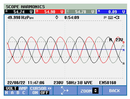
Figure 24.
Three-phase symmetrical supply voltage system under nonlinear load connection.
The power system supplies an industrial oven by means of the uncontrolled three-phase rectifier. The current through the three-phase uncontrolled rectifier is strongly distorted, i.e., nonlinear. Therefore, the nonlinear flow currents conduct to one nonlinear load for the experimental test bench (Figure 25).
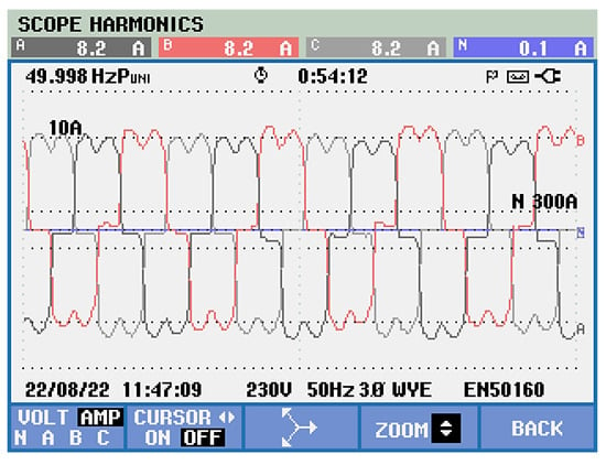
Figure 25.
The three-phase load current shape distortions.
The experimental results are obtained for all three-phases. However, only the experimental results of one phase are presented. In Figure 26, the comparison of the grid phase voltage (54.8 V rms value) with the phase grid current is presented. A strong current deformation can be noted. The rms current value of 8.2 A is increasing due to the connected electric oven.
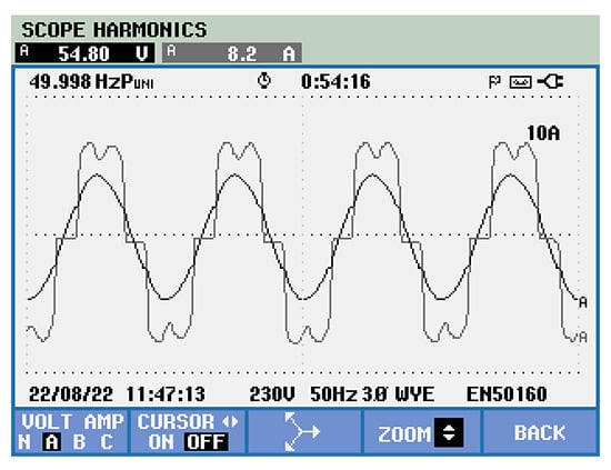
Figure 26.
Comparison between the nonlinear phase current and the grid phase voltage in case of no active power filter control.
The THD was used for both current and voltage signals evaluation as a quality indicator of the harmonic reduction. Quantitative and qualitative evaluation were conducted using the aforementioned Power Analyzer (manufactured by Fluke Corporation, which is headquartered in Everett, WT, USA). Therefore, in the case of no SAPF connection, a high THD value of the load current (THDi = 27.5%) was obtained. According to the block diagram in Figure 1, without harmonic power filter connection, the load current is the same as the supply current of the power source.
In the case of no active power filter control, a harmonics content of 27.5%, respectively 3.6% have been obtained for the phase supply current (Figure 27), and voltage (Figure 28), respectively.
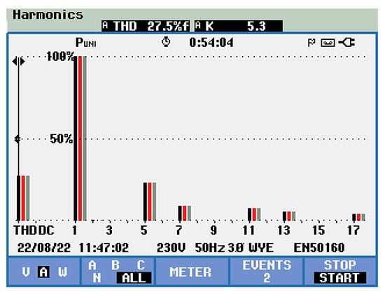
Figure 27.
THD load current indicator of 27.5%.
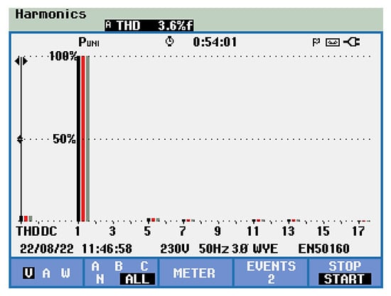
Figure 28.
THD of the power supply voltage in the case of no active filter control.
The symmetrical three-phase supply voltage system is obtained by connecting the harmonic power filter (Figure 29).
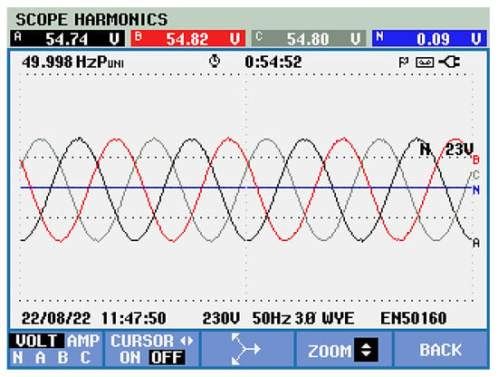
Figure 29.
The symmetrical three-phase supply voltage system in the case of indirect active filter control.
For qualitative comparison, by using indirect active filter control, both power supply signals are delivered (black-phase voltage, gray-phase current) in Figure 30. The sinusoidal shape of the supply current is noted, with reduced harmonics, in phase with the sinusoidal supply voltage.
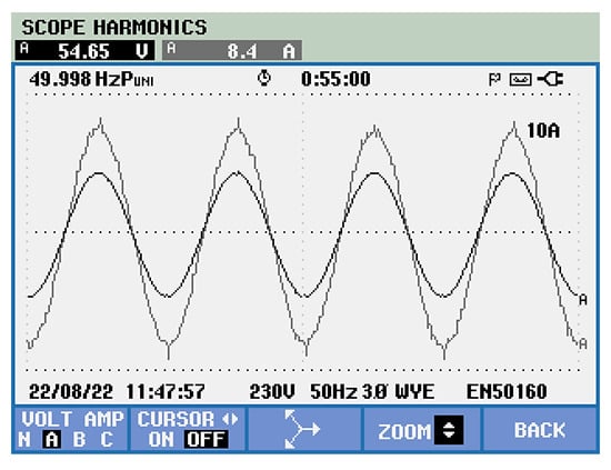
Figure 30.
The phase electric signals of the power supply (black—voltage, gray—current).
The experimental indirect control conduct to the reduced harmonic distortion of the supply current is confirmed by the 3.0% value of the THD current (Figure 31).
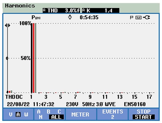
Figure 31.
The experimental phase supply current total harmonic distortion of 3.0% is obtained by using indirect active power filter control.
Moreover, the experimental indirect control conduct to the reduced harmonic distortion of the supply voltage is confirmed by the obtained 0.7% value of the THD voltage (Figure 32).
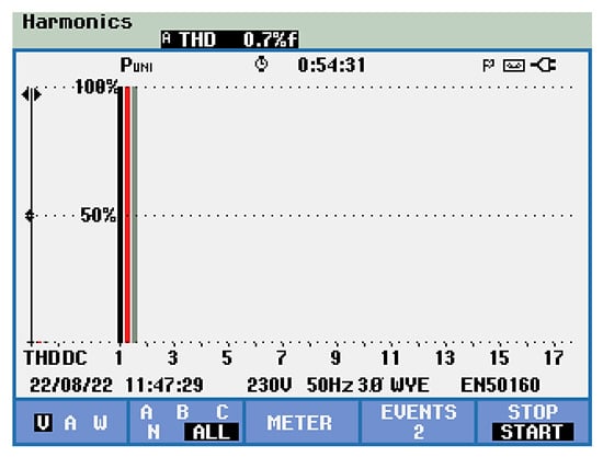
Figure 32.
The experimental phase supply voltage total harmonic distortion of 0.7% is obtained using indirect active power filter control.
As seen in Table 2, the experimentally harmonic content indicators are provided in both cases: with active power filter and without filter connection. By analysing the results, the main objective of the active power with indirect control is reached: low harmonic distortion of the main electric signals (voltage and current) of the power supply. At the level of the harmonic distortion, the comparative experimental results are centralised in Table 2.

Table 2.
Comparison of the harmonic distortion at the level of the phase power supply.
The comparative THD numerical values at the level of the supply phase current demonstrates the obtained high performance of the indirect active power filter control (Figure 33). Moreover, comparative THD numerical values at the level of the supply phase voltage confirm the efficiency of the implemented indirect control (Figure 34).
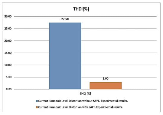
Figure 33.
The experimental results of the total harmonic distortion at the level of the supply phase current in both cases: without indirect active filter control and with harmonic filter connected.
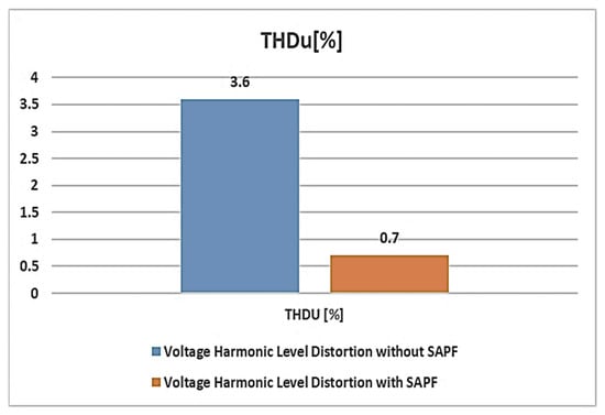
Figure 34.
The experimental results of the total harmonic distortion at the level of the supply phase voltage in both cases: without indirect active filter control and with harmonic filter connected.
It could be noted that the obtained 3.00% THD experimental value for the supply current agrees with both power quality standards IEEE 519-2014 [] and IEC 61000-3-2 [].
In Table 3, the main technical data of the experimental test bench based on the indirect active power filter are depicted [].

Table 3.
The main technical data of the experimental test bench.
According to the data sheet of the IAP100T120 [] three-phase power inverter used, the characteristics of the integrated current transducers maps the range −150 A, 150 A to the range −6 V, 6 V. For the application used in this study, the sensitivity of these transducers is not adequate. It was necessary to increase the sensitivity in the range ±25 A, with a corresponding output signal of ±10 V; therefore, a circuit for amplifying and filtering the signals from the current transducers was required (gain = 10, filtering method—low-pass, cutoff frequency chosen so that the switching frequency of 25 kHz is sufficiently attenuated).
When the control side of the APF is powered up, the voltage and current transducers are self-calibrated [,], before connecting the FAP to the three-phase circuit side. The automatic adjustment involves the creation of a software loop for measuring the offset at system initialization. During the offset determination, null software references are delivered to the input signal to the transducers.
The control algorithm was implemented in the LABVIEW environment, in the form of a loop that runs only at program initialization for 10 s, and simultaneously determines the offset values for all nine transducers in the APF (Figure 35). While this loop is running, the APF is not connected to the power supply, and a null signal is applied to the transducer input.
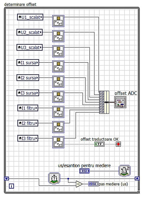
Figure 35.
Obtaining the offset value for used transducers using LabVIEW2017.
The ADC offset value (Figure 35) is obtained by averaging 1000 samples, acquired every 10 ms from the 50 Hz power supply, so that the share of electromagnetic noise caused by the electrical distribution network does not affect the result (equivalent to a notch filter tuned to 50 Hz frequency). In Figure 36, the parameters of a mean value block are shown.
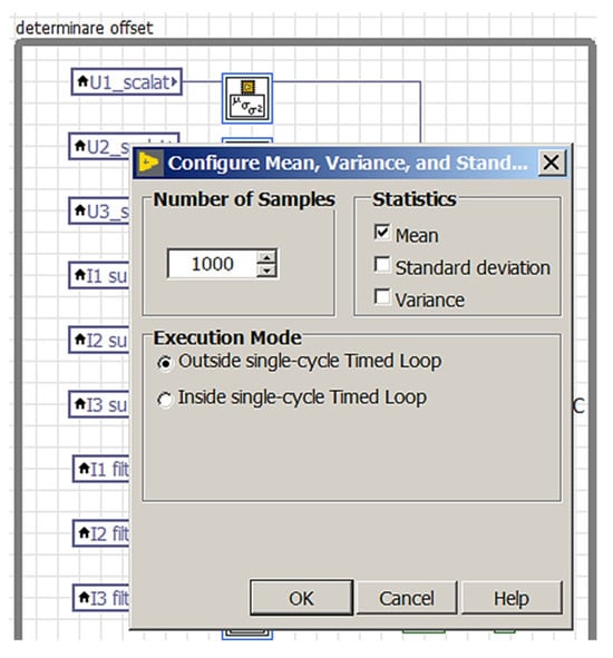
Figure 36.
Parameters of the mean value setting block.
At the end of the software execution, after the acquisition and averaging of the 1000 samples, the mean value block activates the “output valid” signal, displayed as “offset traductoare OK” (transducer offset OK) in the graphical interface of the program, which deactivates the averaging loop (Figure 35). By subtracting the offset value from the signal determined at each analog-to-digital conversion (Figure 37), the useful signal values of each measured quantity are obtained.
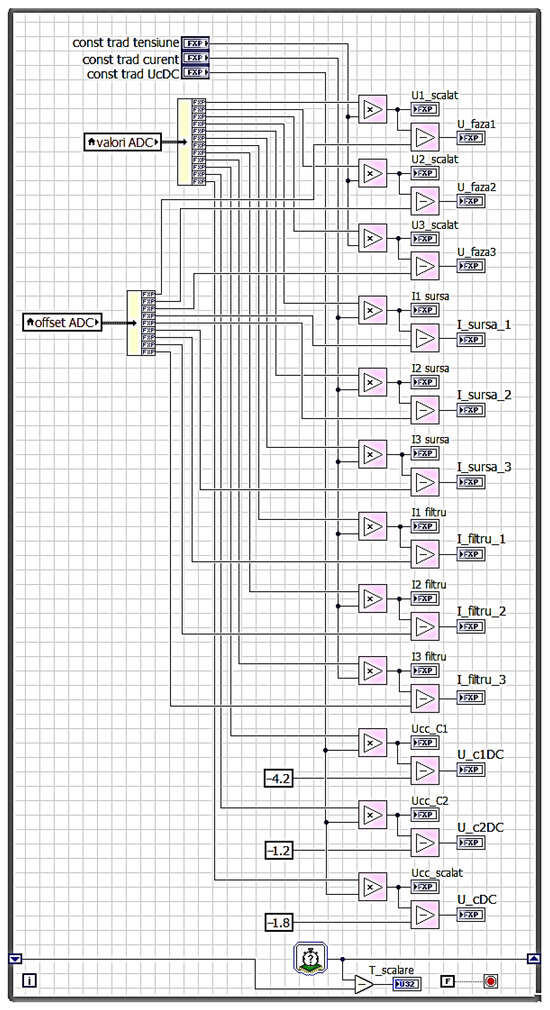
Figure 37.
Obtaining the useful signal for each measured quantity.
To analyze the operation of the transducers, the offset value display block (stored in the digital signal processor) can be used. The displayed offset values are for scaled signals (with the corresponding transducers constant value) and represent up to 5% of the transducer range (Figure 38). For example, the signal displayed in light blue (I filter 1 = I filter 1) represents the output of a current transducer with a range of ±100 A and has an offset of approximately 9° (Figure 38). After the offset self-calibration, the numerical value of the I filter 1 signal becomes less than 0.1° (Figure 39) for zero current reference.
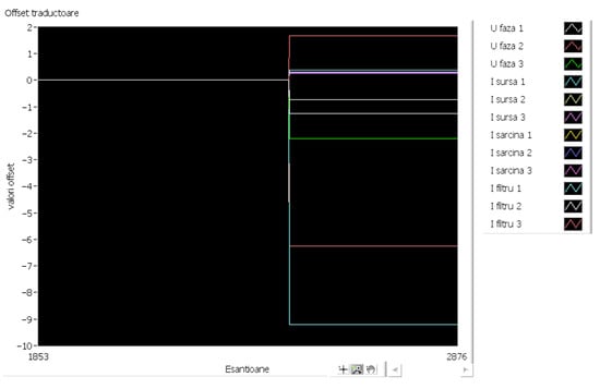
Figure 38.
Display of offset values for the nine transducers.
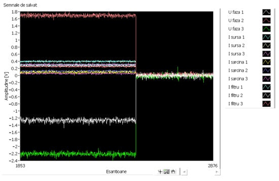
Figure 39.
Autocalibration process completed.
After the offset self-calibration sequence, the output signals converge to zero (Figure 39).
As supported by multiple studies [,,,,], the indirect control approach offers a balanced combination of technical excellence and practical feasibility that outperforms traditional methods in real-world three-phase systems. It especially excels in environments with voltage distortion, load imbalance, and dynamic changes, where conventional methods like SRF, pq or filter-based techniques degrade significantly (Table 4).

Table 4.
Comparative evaluation: Indirect control versus APF control methods.
In Table 4, from the literature review [,,,,], a comparative evaluation of the mentioned control methods (see Table 1) is provided.
Thus, for modern power quality applications—particularly in shunt active power filters, grid-tied inverters, and industrial compensation systems—the indirect approach is not only technically justified but also practically optimal. Indirect control dominates real-world, distorted, or dynamically changing three-phase systems, especially when: voltage distortion or harmonic pollution is present; loads are unbalanced or nonlinear; fast dynamic response is required; simple implementation is desirable (e.g., on DSP, FPGA).
The indirect approach is superior when compared with other modern control strategies used in three-phase power quality applications such as active power filters (APFs), grid-tied inverters and nonlinear load compensation. In power systems with nonlinear and/or unbalanced loads, the goal of control is to ensure: Harmonic compensation; Reactive power mitigation; Power factor correction; Current balancing; Fast dynamic response under load changes.
Modern control strategies include Synchronous Reference Frame (SRF) Control, Instantaneous Power Theory (pq Theory), Predictive Control, Resonant Controller-based Methods, Filtering-based Extraction (e.g., LPF, Notch Filters), Positive Sequence Control, Direct Power Control (DPC).
Among these, the indirect method stands out due to its unique combination of robustness, simplicity, speed, and adaptability (Table 5).

Table 5.
Indirect control features comparison with modern control strategies.
Technical and Practical Advantages
- PLL-Free Operation: Indirect approach avoids PLL, unlike SRF, DPC, or positive sequence-based controllers; PLLs are sensitive to grid voltage noise, unbalance, and phase jumps. This feature enhances robustness and simplifies tuning.
- Time-Domain Simplicity: Works directly in the natural abc frame; No Clarke/Park transform, no coordinate changes. Therefore, there are no frame-related delays or errors. This practical aspect makes it ideal for real-time embedded platforms.
- Fast Transient Response: Indirect control reacts immediately to load changes, since the reference is predefined, not filtered; no LPF or moving average delay is introduced.
- Voltage-Independent Operation: It does not rely on voltage waveform purity; unlike pq or MAX methods, it performs equally well under distorted or nonlinear voltage sources.
- Ideal Reference Signal: Instead of extracting the fundamental current via filters, the desired current waveform is analytically constructed (e.g., proportional to voltage with unity power factor objective). Results in cleaner compensation and better THD performance.
The indirect control approach is technically superior in the control of active power filters and related compensation systems for three-phase power grids. Compared to SRF, pq theory, predictive control, and filtering-based methods, it offers: Greater robustness; Simpler implementation; Better performance under distortion; Lower computational overhead; Ideal suitability for real-time systems.
This makes it the preferred choice in modern industrial and renewable power quality applications where flexibility, speed, and reliability are essential.
By taking into consideration not only present modern control methods but also future oriented techniques (e.g., ML, AI, adaptive/predictive/hybrid methods), the indirect control approach still holds definite advantages; highlighting these helps understand where it remains superior, what trade-offs exist, and how it can evolve. Below are detailed reasons why indirect control is advantageous compared to future modern controls, followed by practical recommendations.
Some of the promising control directions now or coming up include:
- Machine Learning/Neural Networks/Neuro Fuzzy Control in APFs (for harmonic compensation, forecasting loads, fault detection) [].
- Model Predictive Control (MPC) and variants, including predictive methods for converters, hybrid predictive/neural control [].
- Adaptive Control (including indirect adaptive control, MRAC, adaptive controllers that tune with changing plant dynamics) [].
- Hybrid/optimization based/lightweight AI approaches (digital twins, federated ML, hybrid optimization + fuzzy/neural) [].
These are more complex, computationally intensive, sometimes data-driven, sometimes using model learning, etc.
In Table 6, the main technical and practical advantages of indirect control when compared with those future modern methods, especially in three-phase APFs or similar systems, are depicted.

Table 6.
The strength of the indirect control compared with modern control strategies.
In the next table (Table 7), comparison to other APF control approaches is depicted.

Table 7.
Indirect control comparison to other approaches.
In Table 8 a summary of the Shunt Active Power Filter (SAPF) control methods, focusing on their shortcomings addressed and typical Total Harmonic Distortion (THD) achieved, is shown:

Table 8.
Control methods for SAPF—Shortcomings and performance.
From Table 8, it can be seen that the most accurate SAPF control methods are Synchronization with Positive Sequence, SRF and Indirect Control, which offer the best THD performance [,,,,,,,,,,,].
In Table 9, the promising directions for Three-Phase Shunt Active Power Filters (SAPFs) development are provided.

Table 9.
Promising directions for three-phase Shunt Active Power Filters (SAPFs).
The indirect control method does not measure harmonics, being the main advantage. For harmonic measurement, there are some useful methods: Fourier Transform Methods (FFT/DFT) [], Wavelet Transform [], Prony Analysis [], Empirical Mode Decomposition (EMD) [], Artificial Intelligence/Machine Learning Approaches []. The indirect control method proposed in this work offers a computationally efficient, transformation-free, and PLL-independent approach to harmonic compensation. Unlike methods that rely on heavy signal processing (like p–q or SRF theories) or require component extraction and filtering, this approach estimates compensating currents based on the system’s overall power quality needs: enabling faster response, simpler implementation, and robust performance under non-ideal grid conditions.
However, future modern controls may surpass indirect control. The following trade-offs could be mentioned:
- Adaptive learning/generalization: Future methods that adapt or learn may better track changes in load/harmonic spectrum over time, perhaps better than a static indirect control design in highly variable systems.
- Optimality under constraints: Predictive control or optimization-based methods may better handle constraints (e.g., switching losses, voltage constraints, current limits) while optimizing multiple objectives.
- Fault detection, diagnostics, predictive maintenance: ML methods have advantage in prediction and diagnostics that go beyond pure control.
- Hybrid systems: where combine indirect control with learning or model adaptation, or embed a fast predictive element, the increased speed and adaptability may be obtained.
In conclusion, in many realistic future system scenarios, indirect control continues to be a very strong choice:
- Guaranteed baseline performance: It ensures decent THD, balanced currents even without retraining or large datasets.
- Lower risk: Because it is less dependent on data/model training, it is less likely to fail unexpectedly in edge cases.
- Cost effectiveness: For many installations, paying for extra processing hardware, sensor networks, or data infrastructure to support ML/MPC may not be justifiable; indirect control offers good performance at lower cost.
- Regulatory/safety/standard compliance: Easier to certify, debug, and ensure compliance because the behavior is more predictable.
7. Conclusions
In this paper, the validation of the new low-voltage test bench experimental system for current harmonics mitigation was performed. The purpose of this was to develop future control strategies for power quality improvement. The necessary current references to control the active power filter were deducted for both direct and indirect active power filter control methods. In this paper, indirect control was considered. The theoretical side was to provide a guide to improve power quality through active power filters by using both control methods type: direct and indirect. In contrast to direct control, the structure of the indirect control does not contain the harmonic extraction block. In direct control, the harmonics extraction of the shunt active power control is based on the information of the load currents. But the load currents contain both the fundamental and the polluting components. The proposed control method has the advantage of using the sinusoidal power supply current, already measured in the direct control methods. The indirect control has been validated both by simulation and experimental results. At the grid power supply, the obtained total harmonic distortion for the phase current is within the standard harmonic limit (up to 5%). The indirect method uses the minimum number of current transducers. However, the developed experimental test bench has future research activities in view. In this respect, both direct and indirect control are already implemented by the authors in the industrial prototypes powered from the rated grid voltage system. The developed test bench can be used both in European Union and in United States of America power grid cases. Another advantage of the test-bench is the use of parallel computational resources offered by the FPGA processors. While the indirect control strategy itself is well-established and has been validated extensively in prior work, the primary innovation of this research lies in the design and implementation of an FPGA-based test bench. Existing test benches typically rely on software simulation or slower hardware platforms, which can limit real-time performance and precision in validating control algorithms. By leveraging the parallel processing capabilities and deterministic timing of the FPGA, the test bench enables high-speed, real-time testing with greater accuracy and flexibility. The FPGA architecture facilitates rapid prototyping and more comprehensive evaluation of control strategies under realistic operating conditions, bridging the gap between theoretical control designs and practical hardware implementation. Although several control strategies for three-phase Shunt Active Power Filters have been explored in the literature—including the principle of instantaneous powers (p–q theory), the synchronous reference frame algorithm, the maximum detection method, synchronization with the voltage positive sequence component, and signal separation via band-stop or low-pass filters—the experimental results obtained in this work highlight the clear quantitative superiority of the indirect control approach. Furthermore, the FPGA-based implementation of indirect control requires fewer logic resources and simpler signal processing chains, resulting in lower computational complexity and enhanced real-time performance. These results establish indirect control not only as a viable alternative but as a highly efficient, robust, and practical solution for real-world SAPF deployment under dynamic and distorted grid conditions. Based on the provided technical literature, the indirect current control method proves superior to alternative approaches due to a combination of practical implementation simplicity, robustness to non-ideal conditions, and technical performance advantages.
Author Contributions
Conceptualization, M.G. and S.E.; methodology, M.G.; software, M.G. and S.E.; validation, M.G., S.E. and R.C.S.; formal analysis, M.G.; investigation, R.B., C.V.; resources, M.G., S.E., R.B. and R.C.S.; data curation, M.G. and S.E.; writing—original draft preparation, M.G.; writing—review and editing, M.G., S.E., R.B. and R.C.S.; visualization, M.G.; supervision, M.G.; project administration, M.G.; funding acquisition, M.G. All authors have read and agreed to the published version of the manuscript.
Funding
This study was supported by the CRESC INTEL project “Knowledge Transfer Regarding the Energy Efficiency Increase and Intelligent Power Systems”, ID/Cod My SMIS: P_40_340/105803, project co-funded by the European Union from the European Regional Development Fund through the Competitiveness Operational Program 2014–2020.
Data Availability Statement
The original contributions presented are included in this article; further inquiries can be directed to the corresponding author.
Conflicts of Interest
The authors declare no conflicts of interest.
Abbreviations
| AI | Artificial Intelligence |
| APF | Active Power Filter |
| CPU | Central Processing Unit |
| DPC | Direct Power Control |
| DSP | Digital Signal Processor |
| FPGA | Field-Programmable Gate Array |
| MAX | Maximum Method |
| MEM | Memory (RAM—Random Access Memory) |
| ML | Machine Learning |
| MPC | Model Predictive Control |
| MRAC | Model Reference Adaptive Controller |
| NN | Neural Network |
| PCC | Point of Common Coupling |
| PLL | Phase-Locked Loop |
| PWM | Pulse Width Modulation |
| SAPF | Shunt Active Power Filter |
| THD | Total Harmonic Distortion |
References
- Akagi, H.; Watanabe, E.H.; Aredes, M. Instantaneous Power Theory and Applications to Power Conditioning; Wiley: Hoboken, NJ, USA, 2007. [Google Scholar]
- Kim, H.; Blaabjerg, F.; Bak-Jensen, B. Spectral Analysis of Instantaneous Powers in Single-Phase and Three-Phase Systems with Use of p–q–r Theory. IEEE Trans. Power Electron. 2002, 17, 711–720. [Google Scholar] [CrossRef]
- Karimi, H.; Kharimi–Ghartemani, M.; Reza Irvani, M. An Adaptive Filter for Synchronous Extraction of Harmonics and Distortions. IEEE Trans. Power Deliv. 2003, 18, 1350–1356. [Google Scholar] [CrossRef]
- Singh, B.; Al-Haddad, K.; Chandra, A. A review of active filters for power quality improvement. IEEE Trans. Ind. Electron. 1999, 46, 960–971. [Google Scholar] [CrossRef]
- El-Habrouk, M.; Darwish, M.K.; Mehta, P. Active power filters: A review. IEE Proc. Electr. Power Appl. 2000, 147, 403–413. [Google Scholar] [CrossRef]
- Teke, A.; Sarıbulut, L.; Meral, M.; Tumay, M. Active Power Filter: Review of Converter Topologies and Control Strategies. Gazi Univ. J. Sci. 2011, 24, 283–289. [Google Scholar]
- Charles, S.; Bhuvaneswari, G. Comparison of Three Phase Shunt Active Power Filter Algorithms. Int. J. Comput. Electr. Eng. 2010, 2, 175. [Google Scholar] [CrossRef]
- Chen, B.S.; Joss, G. Direct Power Control of Active Filters with Averaged Switching Frequency Regulation. IEEE Trans. Power Electron. 2008, 23, 2729–2737. [Google Scholar] [CrossRef]
- Green, T.C.; Marks, J.H. Control techniques for active power filters. IEE Proc. Electr. Power Appl. 2005, 152, 369–381. [Google Scholar] [CrossRef]
- Montero, M.I.M.; Cadaval, E.R.; Gonzalez, F.B. Comparison of Control Strategies for Shunt Active Power Filters in Three-Phase Four-Wire Systems. IEEE Trans. Power Electron. 2007, 22, 229–236. [Google Scholar] [CrossRef]
- Rosu, E.; Culea, M.; Dumitriu, T.; Munteanu, T.; Paduraru, R. Active power filter with indirect control for line-frequency controlled rectifiers. Ann. “Dunarea De Jos” Univ. Galati Fascicle III Electrotech. Electron. Autom. Control. Inform. 2009, 32. [Google Scholar]
- Xu, Y.; Xiao, X.; Liu, L. New approaches of low cost hybrid active filter. In Proceedings of the Electric Power Engineering, Budapest, Hungary, 29 August–2 September 1999; p. 291. [Google Scholar]
- Telmo Santos, J.; Pinto, G.; Neves, P.; Gonçalves, D.; Afonso, J.L. Comparison of Three Control Theories for Single-Phase Active Power Filters. In Proceedings of the IECON 2009—The 35th Annual Conference of the IEEE Industrial Electronics Society, Porto, Portugal, 3–5 November 2009. [Google Scholar]
- Epure, S.; Rosu, E. Indirect Control of a low power Single-Phase Active Power Filter. In The Annals of “Dunarea De Jos”; University of Galati: Galati, Romania, 2010. [Google Scholar]
- Ionescu, F.; Six, J.P.; Floricau, D.; Delarue; Nitu, S.; Bogus, C. Electronica de Putere. Convertoare Statice (Power Electronics. Static Converters); Editura Tehnica: Bucuresti, Romania, 1998. [Google Scholar]
- Areerak, K.-L.; Narongrit, T. Shunt active power filter design using genetic algorithm method. Wseas Trans. Syst. 2010, 9, 348–357. [Google Scholar]
- Sundaram, E.; Gunasekaran, M.; Krishnan, R.; Padmanaban, S.; Chenniappan, S.; Ertas, A.H. Genetic algorithm based reference current control extraction based shunt active power filter. Int. Trans. Electr. Energy Syst. 2021, 31, e12623. [Google Scholar] [CrossRef]
- EN IEC 61000-6-2:2019; Electromagnetic Compatibility (EMC)—Part 6-2: Generic Standards—Immunity Standard for Industrial Environments. International Electrotechnical Commission: Geneva, Switzerland, 2019.
- EN IEC 61000-6-4:2019; Electromagnetic Compatibility (EMC)—Part 6-4: Generic Standards—Emission Standard for Industrial Environments. International Electrotechnical Commission: Geneva, Switzerland, 2019.
- EN 50178:1997; Electronic Equipment for Use in Power Installations. European Standard: Brussels, Belgium, 1997.
- Jiang, B.; Wang, Q.; Wu, S.; Wang, Y.; Lu, G. Advancements and Future Directions in the Application of Machine Learning to AC Optimal Power Flow: A Critical Review. Energies 2024, 17, 1381. [Google Scholar] [CrossRef]
- Jai, A.A.; Ouassaid, M. Three novel machine learning-based adaptive controllers for a photovoltaic shunt active power filter performance enhancement. Sci. Afr. 2024, 24, e02171. [Google Scholar] [CrossRef]
- Jai, A.A.; Ouassaid, M. Machine Learning-Based Adaline Neural PQ Strategy for a Photovoltaic Integrated Shunt Active Power Filter. IEEE Access 2023, 11, 56593–56618. [Google Scholar] [CrossRef]
- Wang, Q.; Li, Y.; Li, R. Integrating artificial intelligence in energy transition: A comprehensive review. Energy Strategy Rev. 2025, 57, 101600. [Google Scholar] [CrossRef]
- Salam, M.H.U.; Rathore, S.A.; Irfan, M.; Abbas, T.; Janjua, J.I. Artificial Intelligence-Integrated Series Active Filters for Improved Power Quality in EV Infrastructure. Spectr. Eng. Sci. 2025, 3, 522–556. [Google Scholar]
- Nishad, D.K.; Tiwari, A.N.; Khalid, S.; Gupta, S.; Shukla, A. AI based UPQC control technique for power quality optimization of railway transportation systems. Sci. Rep. 2024, 14, 17935. [Google Scholar] [CrossRef] [PubMed]
- Pande, N.; Ohnishi, W.; Koseki, T. Analysis of voltage unbalance and mitigation of circulating power in bilateral co-phase traction system. Electr. Power Syst. Res. 2024, 228, 110048. [Google Scholar] [CrossRef]
- Taghvaie, A.; Warnakulasuriya, T.; Kumar, D.; Zare, F.; Sharma, R.; Vilathgamuwa, D.M. A Comprehensive Review of Harmonic Issues and Estimation Techniques in Power System Networks Based on Traditional and Artificial Intelligence/Machine Learning. IEEE Access 2023, 11, 31417–31442. [Google Scholar] [CrossRef]
- Senthil, P.; Kumar, P.V.; Jayakumar, J. Modelling and Regulating Active Harmonic Filters For Improve Power Quality In Transmission Line Environment. Int. J. Comput. Exp. Sci. Eng. 2025, 11, 4479–4490. [Google Scholar] [CrossRef]
- Mariusz Cichowlas, M.S. PWM Rectifier with Active Filtering. Ph.D. Thesis, Warsaw University of Technology, Warsaw, Poland, 2004. [Google Scholar]
- Marian, G.; Ionut, E.S.; Constantin, S.R.; Razvan, B. Unified Implementation of Six Direct Control Method for FAP-OL Three Phase, Low-Voltage, Parallel-Type Active Power Filters Used in Experimental Stand and in Active Power Filters Prototypes, Involves Carrying out Switching Between Methods Online Without Interrupting Operation of System. Patent RO137988(A2), 25 August 2022. [Google Scholar]
- Marian, G.; Ionut, E.S.; Constantin, S.R.; Razvan, B.; Alexandru, D.; Iulian, G. Experimental System for Implementing and Testing Parallel-Type Three-Phase Low-Voltage Active Electronic Power Filters, Has Programmable Three-Phase Electrical Loads and Some Interface Inductances Provided Between Voltage Inverter and Common Source-Polluting Load Connection Point. Patent RO137368-A2, 21 October 2021. [Google Scholar]
- Available online: http://cresc-intel.ugal.ro/images/Filme/0FAP0L_UGAL.mp4 (accessed on 7 August 2025).
- Available online: https://www.appliedps.com/iap100t120-sixpac (accessed on 7 August 2025).
- Available online: http://cresc-intel.ugal.ro/images/Filme/1_UGAL.mp4 (accessed on 7 August 2025).
- Available online: http://cresc-intel.ugal.ro/images/Filme/2_UGAL.mp4 (accessed on 7 August 2025).
- Available online: http://cresc-intel.ugal.ro/images/Filme/3_UGAL.mp4 (accessed on 7 August 2025).
- Available online: http://cresc-intel.ugal.ro/images/Filme/4_UGAL.mp4 (accessed on 7 August 2025).
- Available online: http://cresc-intel.ugal.ro/images/Filme/5_UGAL.mp4 (accessed on 7 August 2025).
- Available online: http://cresc-intel.ugal.ro/images/Filme/6_UGAL.mp4 (accessed on 7 August 2025).
- Available online: http://cresc-intel.ugal.ro/images/Filme/7_UGAL.mp4 (accessed on 7 August 2025).
- Gaiceanu, M.; Epure, S.; Solea, R.C.; Buhosu, R. Power Quality Improvement with Three-Phase Shunt Active Power Filter Prototype Based on Harmonic Component Separation Method with Low-Pass Filter. Energies 2025, 18, 556. [Google Scholar] [CrossRef]
- Ionescu, F.; Nitu, S.; Rosu, E. Preocupari Actuale in Domeniul Electronicii de Putere; Editura Secorex: Bucuresti, Romanian, 2001; ISBN 973-85298-3-2. [Google Scholar]
- IEEE Standard 519; IEEE Recommended Practice and Requirement for Harmonic Control in Electric Power Systems. IEEE: Piscataway, NJ, USA, 2014; pp. 1–29.
- IEC 61000-3-2:2018+AMD1:2020 CSV; Electromagnetic Compatibility (EMC)—Part 3-2: Limits—Limits for Harmonic Current Emissions (Equipment Input Current ≤16 A per Phase). IEC 61000-3-2 Consolidated Version. International Electrotechnical Commission: Geneva, Switzerland, 2018.
- Hu, Z.-K.; Chen, Z.-W.; Hua, C.-C.; Ding, J.-F. A novel digital control strategy of three-phase shunt active power filter under non-ideal mains voltages. J. Cent. South Univ. 2011, 18, 436–443. [Google Scholar] [CrossRef]
- Hwang, J.-G.; Park, Y.-J.; Choi, G.-H. Indirect current control of active filter for harmonic elimination with novel observer-based noise reduction scheme. Electr. Eng. 2005, 87, 423–433. [Google Scholar] [CrossRef]
- Hoon, Y.; Mohd Radzi, M.A.; Hassan, M.K.; Mailah, N.F. Enhanced Instantaneous Power Theory with Average Algorithm for Indirect Current Controlled Three-Level Inverter-Based Shunt Active Power Filter under Dynamic State Conditions. Math. Probl. Eng. 2016, 2016, 9682512. [Google Scholar] [CrossRef]
- Zhu, H.; Shu, Z.; Gao, F.; Qin, B.; Gao, S. Five-level diode-clamped active power filter using voltage space vector-based indirect current and predictive harmonic control. IET Power Electron. 2014, 7, 713–723. [Google Scholar] [CrossRef]
- Popescu, M.; Bitoleanu, A.; Suru, C.V.; Linca, M.; Alboteanu, L. Shunt active power filters in three-phase, three-wire systems: A topical review. Energies 2024, 17, 2867. [Google Scholar] [CrossRef]
- Chahine, K. Machine Learning in Active Power Filters: Advantages, Limitations, and Future Directions. AI 2024, 5, 2433–2460. [Google Scholar] [CrossRef]
- Pan, H.; Sun, Y.; Chen, D.; Tan, W.; Liu, J. Improved backward model predictive control for modular multilevel active power filter. Int. J. Dynam. Control 2024, 12, 3236–3247. [Google Scholar] [CrossRef]
- Ray, P.K.; Swain, S.D. Performance enhancement of shunt active power filter with the application of an adaptive controller. IET Gener. Transm. Distrib. 2020, 14, 4444–4451. [Google Scholar] [CrossRef]
- Aslam, S.; Aung, P.P.; Rafsanjani, A.S.; Majeed, A.P.A. Machine learning applications in energy systems: Current trends, challenges, and research directions. Energy Inform. 2025, 8, 62. [Google Scholar] [CrossRef]
- Tiyarachakun, A.; Yuttitham, K.; Chomsuwan, K. Instantaneous Power Theory with Fourier and Optimal Predictive Controller Design for Shunt Active Power Filter. Math. Probl. Eng. 2014, 2014, 381760. [Google Scholar] [CrossRef]
- Villalón, A.; Burgos-Mellado, C.; Rivera, M.; Zuloaga, R.; Levis, H.; Wheeler, P.; García, L.Y. Real-Time Model Predictive Control for Two-Level Voltage Source Inverters with Optimized Switching Frequency. Appl. Sci. 2025, 15, 7365. [Google Scholar] [CrossRef]
- Hoon, Y.; Mohd Radzi, M.A.; Hassan, M.K.; Mailah, N.F. A Refined Self-Tuning Filter-Based Instantaneous Power Theory Algorithm for Indirect Current Controlled Three-Level Inverter-Based Shunt Active Power Filters under Non-sinusoidal Source Voltage Conditions. Energies 2017, 10, 277. [Google Scholar] [CrossRef]
- Akagi, H. New trends in active filters for power conditioning. IEEE Trans. Ind. Appl. 1996, 32, 1312–1322. [Google Scholar] [CrossRef]
- Chaudhari, M.B.; Patel, N.D.; Bhavsar, P.R.; Vaghamshi, A.L.; Mali, S.D.; Patni, V.N.; Jaradi, P.K.; Trivedi, T.; Gupta, C. Implementation of Shunt Active Power Filter using DSP Controller based on Synchronous Reference Frame for Harmonic Mitigation. J. Electr. Syst. 2020, 20, 4565–4570. Available online: https://journal.esrgroups.org/jes/article/view/5824 (accessed on 4 July 2025).
- Izzati, I.; Harun, A. Harmonic Mitigation using Shunt Active Power Filter Based on Synchronous Reference Frame Theory. UNIMAS Institutional Repository 2023. Available online: https://ir.unimas.my/id/eprint/43095/ (accessed on 4 July 2025).
- Musa, S.; Mohd Radzi, M.A.; Hizam, H.; Abdul Wahab, N.I.; Hoon, Y.; Mohd Zainuri, M.A.A. Modified Synchronous Reference Frame Based Shunt Active Power Filter with Fuzzy Logic Control PWM Inverter. Energies 2017, 10, 758. [Google Scholar] [CrossRef]
- Khanesar, A.; Kayacan, E.; Teshnehlab, M.; Kaynak, O. Extended Kalman Filter Based Learning Algorithm for Type-2 Fuzzy Logic Systems and Its Experimental Evaluation. IEEE Trans. Ind. Electron. 2012, 59, 4443–4455. [Google Scholar] [CrossRef]
- Escobar, G.; Pettersson, S.; Ho, C.N.M. Phase-locked loop for grid synchronization under unbalanced operation and harmonic distortion. In Proceedings of the 37th Annual Conference of the IEEE Industrial Electronics Society, Melbourne, Australia, 7–10 November 2011; pp. 675–680. [Google Scholar] [CrossRef]
- Teodorescu, R.; Liserre, M.; Rodriguez, P. Grid Converters for Photovoltaic and Wind Power Systems; Wiley-IEEE Press: Hoboken, NJ, USA, 2011. [Google Scholar] [CrossRef]
- Singh, B.N.; Singh, B.; Chandra, A.; Al-Haddad, K. Design and digital implementation of active filter with power balance theory. IEE Proc. Electr. Power Appl. 2005, 152. [Google Scholar] [CrossRef]
- Singh, M.; Chandra, A. Application of Adaptive Network-Based Fuzzy Inference System for Sensorless Control of PMSG-Based Wind Energy Conversion System. IEEE Trans. Power Electron. 2010, 26, 165–175. [Google Scholar] [CrossRef]
- Amara, A. Design and Control of Active Power Filters with Adaptive Techniques. Master’s Thesis, Politecnico di Milano, Milano, Italy, 2019. [Google Scholar]
- Panigrahi, R.; Subudhi, B.; Panda, P.C. Model predictive-based shunt active power filter with a new reference current estimation strategy. IET Power Electron. 2015, 8, 221–233. [Google Scholar] [CrossRef]
- Abdallah, S.M.; Ahmed, M.R. Active Damping Techniques for LCL Filters in Grid-Connected Inverters; Springer International Journal of Electrical Engineering: Berlin/Heidelberg, Germany, 2018. [Google Scholar]
- Baros, J.; Sotola, V.; Bilik, P.; Martinek, R.; Jaros, R.; Danys, L.; Simonik, P. Review of Fundamental Active Current Extraction Techniques for SAPF. Sensors 2022, 22, 7985. [Google Scholar] [CrossRef]
- Deffaf, B.; Farid, H.; Benbouhenni, H.; Medjmadj, S.; Debdouche, N. Synergetic control for three-level voltage source inverter-based shunt active power filter to improve power quality. Energy Rep. 2023, 10, 1013–1027. [Google Scholar] [CrossRef]
- Chen, Y.; Yang, S.; Kong, Y.; Chen, M. Kalman-Filtering-Based Frequency Control Strategy Considering Electrolytic Aluminum Load. Energy Eng. 2022, 119, 1517–1529. [Google Scholar] [CrossRef]
- Cong, L.; Ke, D.; Xinwen, C.; Yuqing, H.; Pingjiang, L. Selective harmonic suppression strategy by SAPF in power distribution system. J. Eng. 2017, 2017, 1610–1613. [Google Scholar] [CrossRef]
- Barik, P.K.; Samal, S.; Gupta, D.K.; Appasani, B.; Jha, A.V.; Islam, M.M.; Ustun, T.S. Split-source inverter with adaptive control scheme-based shunt active power filter for power quality improvement. IET Power Electron. 2024, 17, 1893–1910. [Google Scholar] [CrossRef]
- Heguig, L.; Mesbahi, N.; Guettaf, Y. Control of shunt active power filter for power quality improvements with PV system using MPC approach. Int. J. Power Electron. Drive Syst. 2025, 16, 278–286. [Google Scholar] [CrossRef]
- Daniel, K.; Kütt, L.; Iqbal, M.N.; Shabbir, N.; Raja, H.A.; Sardar, M.U. A Review of Harmonic Detection, Suppression, Aggregation, and Estimation Techniques. Appl. Sci. 2024, 14, 10966. [Google Scholar] [CrossRef]
- Kumar, V.; Gawre, S.; Kumar, T. Power Quality Analysis Using Wavelet Transform: A Review. Int. J. Innov. Res. Sci. Eng. Technol. 2014, 3, 130–136. [Google Scholar]
- Gong, J.; Liu, S. A Harmonic and Interharmonic Detection Method for Power Systems Based on Enhanced SVD and the Prony Algorithm. Appl. Sci. 2023, 13, 7558. [Google Scholar] [CrossRef]
- Lu, Z.; Smith, J.S.; Wu, Q.H.; Fitch, J. Empirical Mode Decomposition For Power Quality Monitoring. In Proceedings of the 2005 IEEE/PES Transmission & Distribution Conference & Exposition: Asia and Pacific, Dalian, China, 18 August 2005; pp. 1–5. [Google Scholar] [CrossRef]
- Chen, L.; Hu, J.; Luo, Z. An Improved Low-Pass Filter for Instantaneous Reactive Power Theory Based SAPF Control. IOP Conf. Ser. Earth Environ. Sci. 2020, 446, 052094. [Google Scholar] [CrossRef]
Disclaimer/Publisher’s Note: The statements, opinions and data contained in all publications are solely those of the individual author(s) and contributor(s) and not of MDPI and/or the editor(s). MDPI and/or the editor(s) disclaim responsibility for any injury to people or property resulting from any ideas, methods, instructions or products referred to in the content. |
© 2025 by the authors. Licensee MDPI, Basel, Switzerland. This article is an open access article distributed under the terms and conditions of the Creative Commons Attribution (CC BY) license (https://creativecommons.org/licenses/by/4.0/).