Abstract
The tooth harmonics caused by stator slots are a major factor leading to low motor efficiency, high temperature rise and severe vibration. The application of a magnetic slot wedge (MSW) can effectively mitigate the adverse effects of the stator slot on the motor. However, it should also be noted that the MSW may be subject to the action of electromagnetic forces during motor operation and thus has a risk of falling off. In order to comprehensively analyze the impact of MSW on the electromagnetic and reliability performance of the motor, this paper selected three types of MSW with relative permeabilities of 5, 10 and 15 to be applied in a high-power line-start permanent magnet synchronous motor (LSPMSM). The effects of these three types of MSWs on the electromagnetic performance of the motor and the changes in the electromagnetic force acting on the MSW were studied. Finally, the research content of the paper was verified on a 630 kW, 6 kV, 4-pole LSPMSM, providing a reference for the selection and application of MSW in motors.
1. Introduction
The high-power LSPMSM can achieve high efficiency and high power factor under a wide load range, and it can drive large pumps to start and operate without the need for a frequency converter. Therefore, it is widely used by customers in the industrial pump and blower fields [1,2,3,4,5,6,7]. However, in order to facilitate flat-wire winding, the stator slots of high-power motors are made into open slot types. The tooth harmonics caused by the stator slot lead to phenomena such as motor core loss, stray loss, vibration noise, and increased temperature rise, which are not conducive to efficient development of the motor [8]. However, the application of MSWs can effectively weaken the adverse effects of tooth harmonics on the motor, but at the same time, attention should also be paid to the risk of detachment and other drawbacks of MSWs [9].
The application of MSWs can enhance the performance of the motor, including reducing temperature rise, minimizing vibration and improving efficiency [10,11,12]. However, at the same time, MSWs also cause an increase in the leakage reactance of the motor stator slots, which is not conducive to the starting performance of asynchronous motors [13,14]. In order to solve the drawback of the conventional MSW where the increased slot leakage reactance leads to a decrease in torque, anisotropic MSWs have been widely studied [15]. They achieve the effect of reducing the amplitude of the tooth harmonic magnetic field without increasing the leakage reactance of the stator slots.
Although the above studies have proved that the application of MSWs is beneficial to improving the electromagnetic performance of the motor, none of them have taken into account the risk of the MSW falling off. Mechanical problems of MSWs include situations where the size of the MSW is either too large or too small, which can cause the wedge to become loose and undergo compression deformation. These are the main factors causing problems with the MSW. Proper use of an MSW can enable the motor to operate safely for 25 years [16]. Other factors also affect the service life of the MSW, and this has been studied [17]. However, existing papers rarely focus on the force conditions that the MSW experiences in the air gap magnetic field.
In order to comprehensively analyze the application of MSW in permanent magnet motors, this paper built a 630 kW, 6 kV, 4-pole LSPMSM model. Firstly, it studied the impact of the MSW on motor loss. Secondly, it analyzed the Maxwell stress and Ampere force that the MSW is subjected to. The research in this paper can provide a reference for motor manufacturers in selecting an MSW.
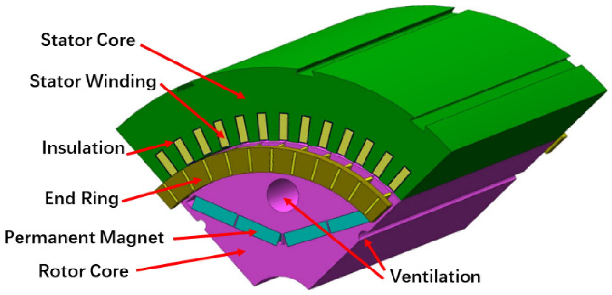
The rotor of the high-power LSPMSM was equipped with a rotor squirrel-cage. At the same time, to facilitate heat dissipation of the rotor, eight ventilation holes were also designed inside it. The model of the motor structure at one-eighth scale is shown in Figure 1. The electromagnetic parameters of the motor are presented in Table 1.
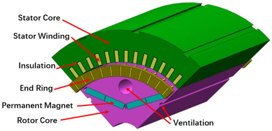
Figure 1.
Structure of LSPMSM.

Table 1.
Parameters of LSPMSM.
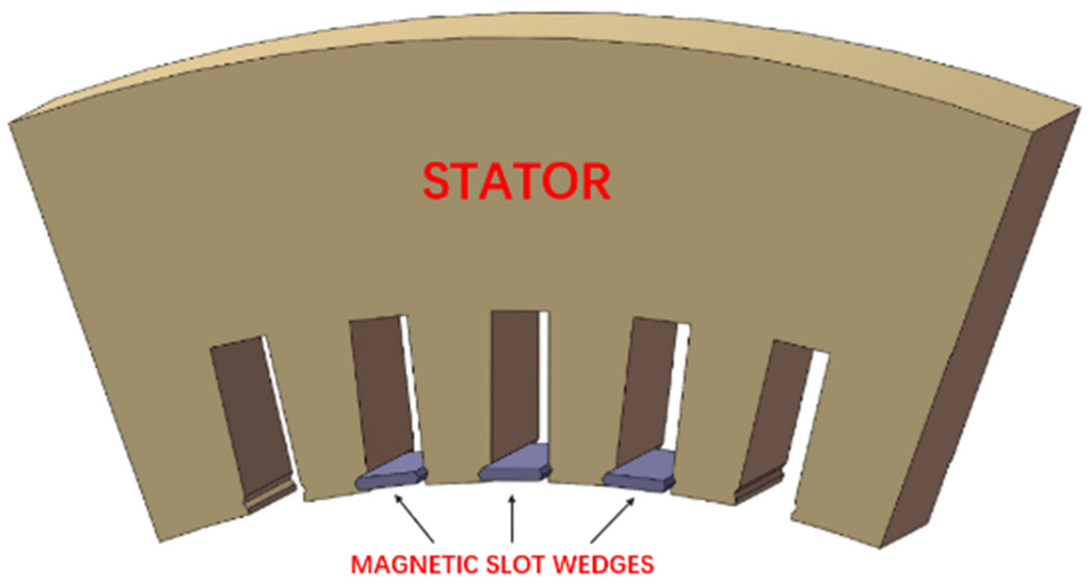
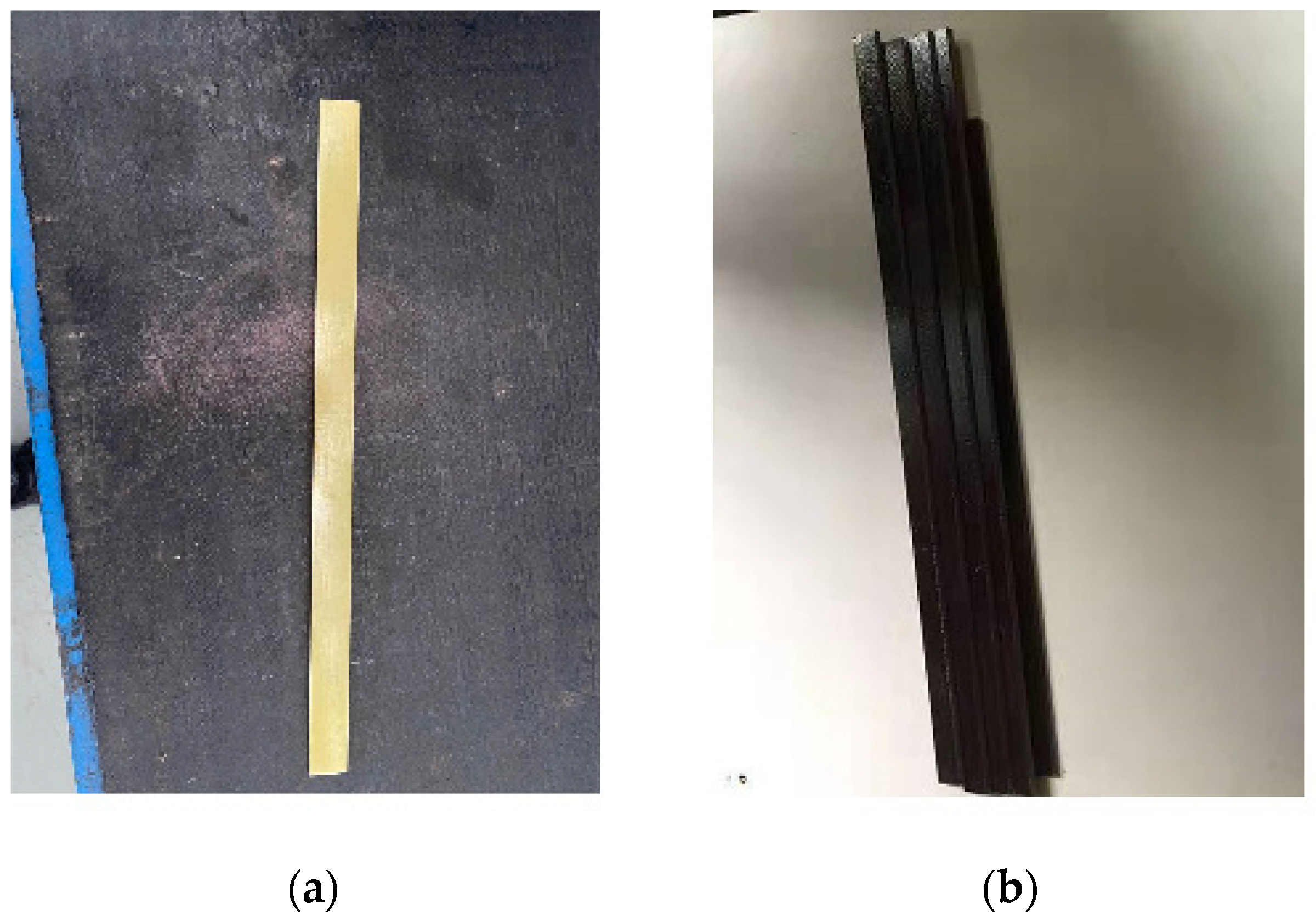
The stator windings of the high-power motor adopted the rectangular winding type. To cover the windings and prevent them from falling out of the iron core and to weaken the influence of tooth harmonics, MSWs were installed in the stator core, as shown in Figure 2. The MSW is different from the epoxy resin slot wedge we usually use, and was composed of 70% iron powder, 10% glass material, and 20% epoxy resin. As shown in Figure 3, the MSW is a dark rectangular strip because of the iron powder added to enhance permeability.
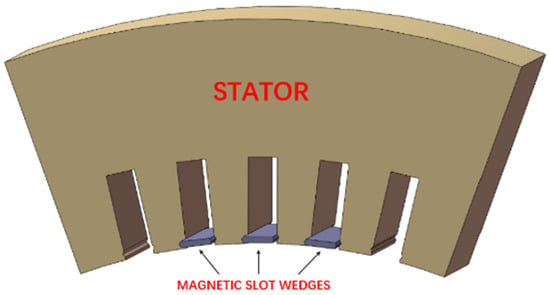
Figure 2.
Stator core and MSWs.
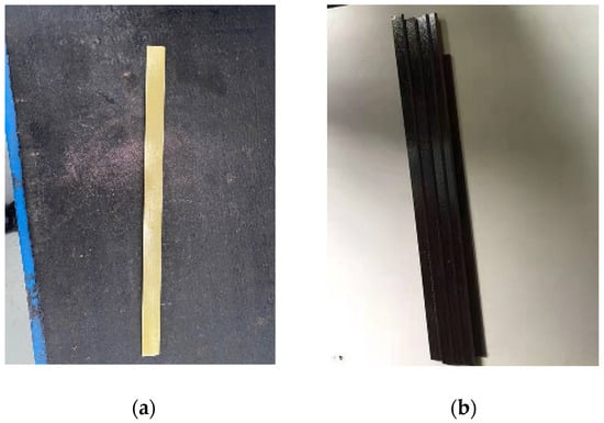
Figure 3.
Stator slot wedge: (a) Resin slot wedge; (b) MSW [18].
2. Motor Loss Analysis
When MSWs are applied to an LSPMSM, the air gap magnetic field distribution during no-load operation will change, and the amplitude of the air-gap harmonic magnetic field will be weakened. Therefore, the core loss of the motor will be affected by the MSWs. This section mainly analyzes the changes in motor copper loss and core loss after applying MSWs to the LSPMSM, and explores the degree of influence of MSWs with different relative permeability on motor loss.
2.1. The Influence of MSWs on the Air-Gap Magnetic Field
The application of MSW in the motor causes the air-gap magnetic field waveform of the motor to change when it is in no-load condition, and weakens the amplitude of the tooth harmonic magnetic field. In order to analyze the influence of different relative permeabilities of MSWs on the air-gap magnetic field of the motor in no-load condition, a finite element model was established based on the parameters in Table 1, and four types of MSW were analyzed and studied. Among them, μr represents the relative permeability of the MSW, and it should be particularly noted that when the μr value is 1, it indicates that the open slot has no installed MSW.
- (1)
- MSW1 (μr = 1);
- (2)
- MSW2 (μr = 5);
- (3)
- MSW3 (μr = 10);
- (4)
- MSW4 (μr = 15);
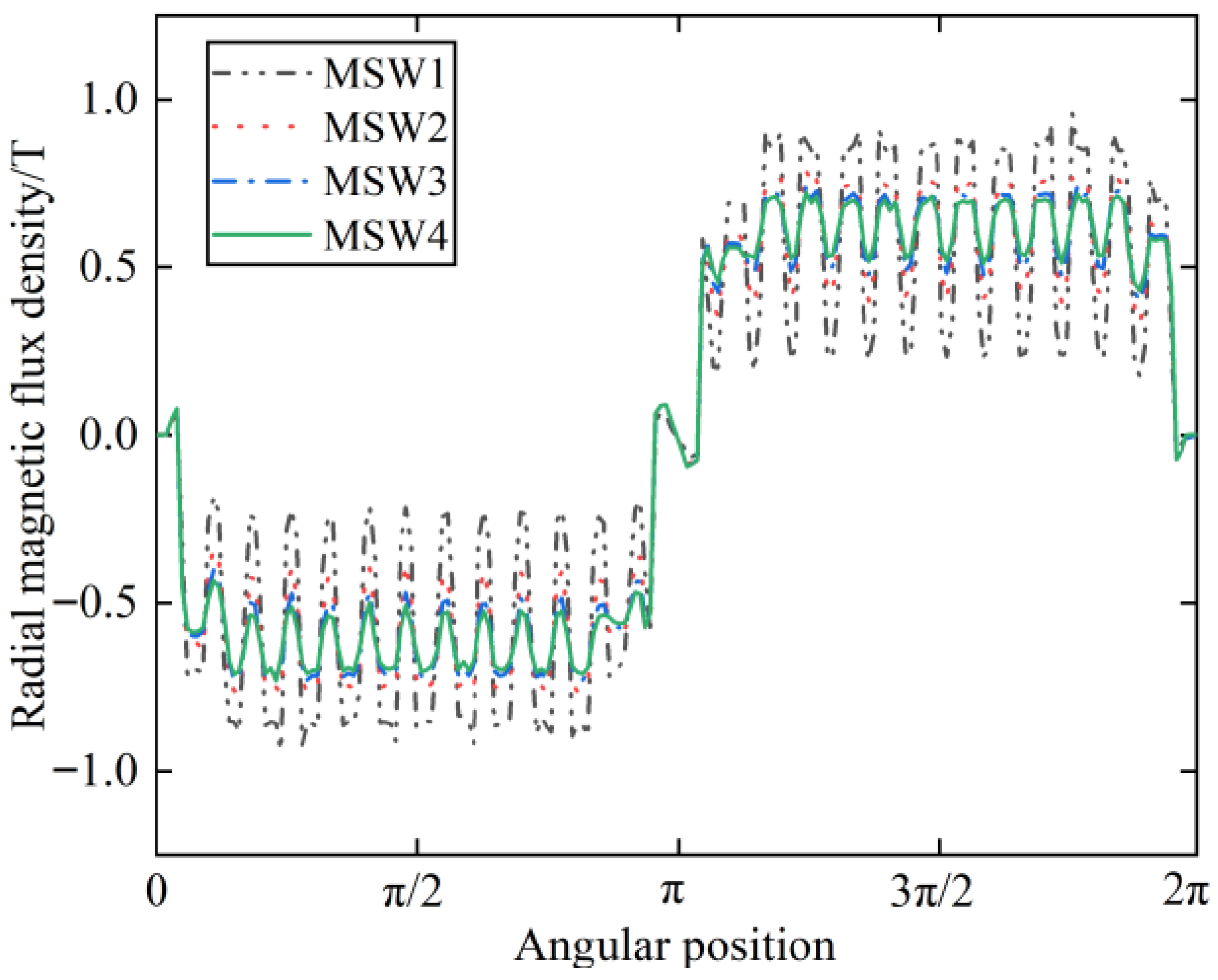
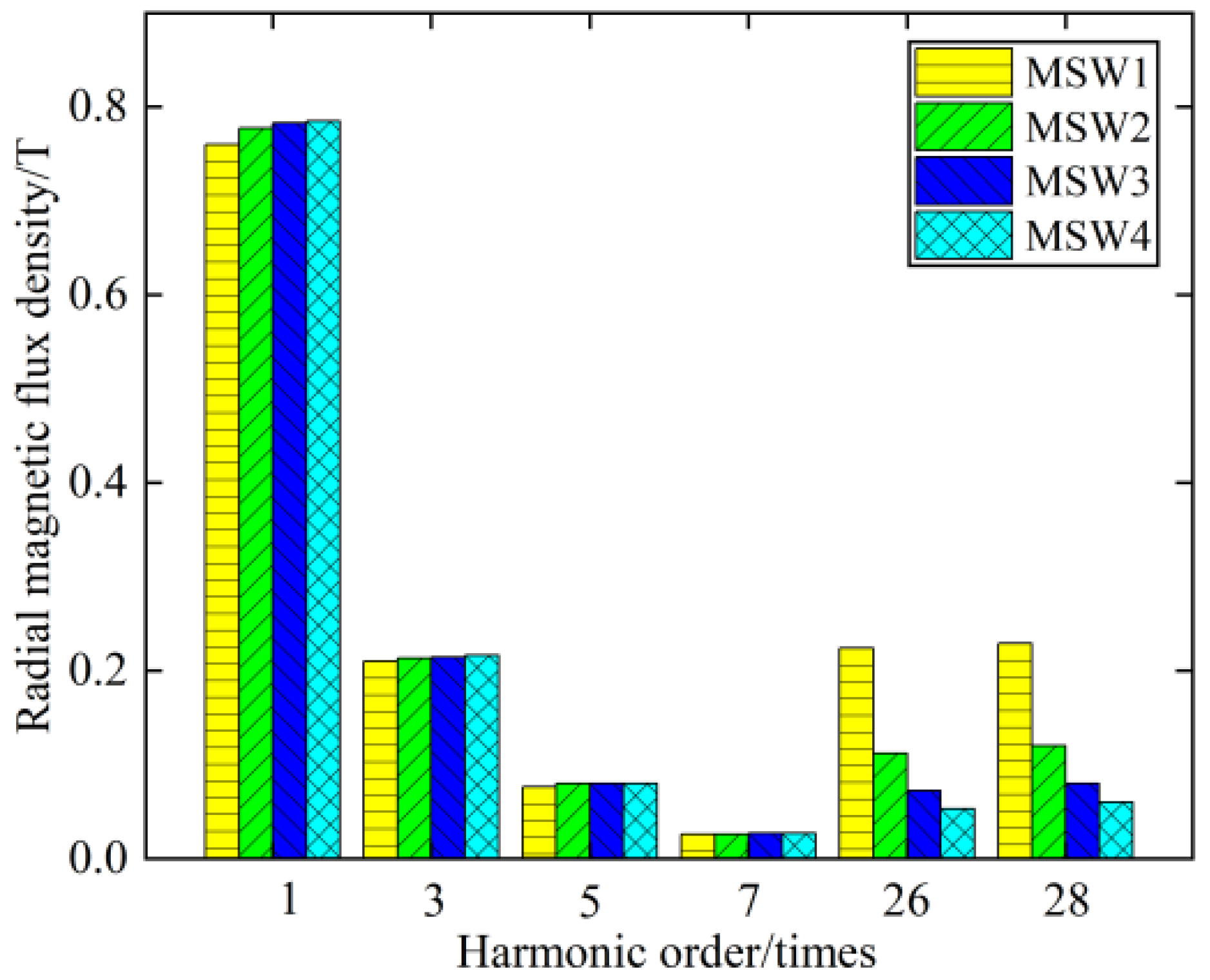
The influence of MSW on the no-load air gap magnetic field of the motor was studied using the finite element method as shown in Figure 4. From Figure 4, it can be seen that as the relative permeability value of the MSW increases, the fluctuations of the no-load radial air gap magnetic field are suppressed, indicating that the amplitude of the harmonic magnetic field is weakened by the MSW. According to the expression of the tooth harmonic order, the tooth harmonic order υZ is related to the number of stator slots and the number of poles as shown in Formula (1). Given that the stator slot number of the motor is 54 and the number of poles is 4, the first-order tooth harmonic orders can be calculated as 26th and 28th. Fourier analysis of the air gap magnetic field reveals the variation in the harmonic magnetic field amplitude shown in Figure 5.
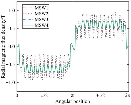
Figure 4.
Radial air-gap magnetic field waveforms under different MSW.
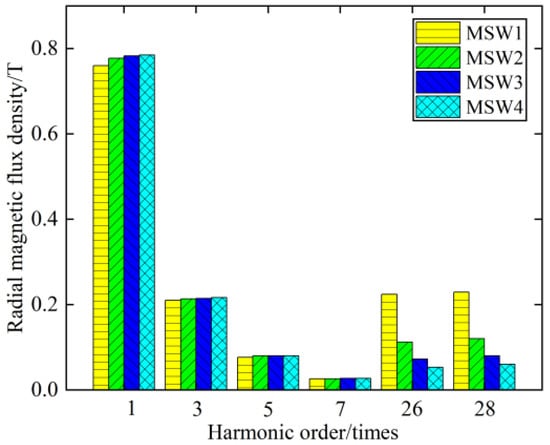
Figure 5.
Comparison of air gap magnetic field orders.
From Figure 5, it can be seen that as the relative permeability of the MSW gradually increases, the amplitude of the fundamental magnetic field of the motor increases to a certain extent, but the 3rd, 5th, and 7th harmonics are not significantly affected. Particularly, it is noted that the tooth harmonic magnetic fields, namely the 26th and 28th magnetic fields, are effectively weakened. Considering that only higher-order harmonics with relatively larger amplitudes in the no-load air-gap magnetic field could have a significant impact on motor performance, the paper only analyzed the fundamental wave, 3rd, 5th, and 7th harmonics. By comparison, it can be concluded that the amplitude of the 7th harmonic magnetic field is almost unaffected by the MSW. Therefore, the 9th and 11th harmonic magnetic fields were not included in the figure. The 26th and 28th harmonics are first-order tooth harmonic magnetic fields that are greatly influenced by the MSW, while the 53rd and 55th harmonics are second-order tooth harmonic magnetic fields with smaller amplitudes.
Through the above analysis, it can be concluded that the MSW has a significant effect on suppressing the tooth harmonic magnetic fields.
where Z represents the number of stator slots; P represents the pole pairs.
2.2. The Influence of MSW on Core Loss
Core loss of the motor is mainly generated by the rotating magnetic field on the stator and rotor core, and is divided into three parts: eddy current loss, magnetic hysteresis loss and stray loss. In the previous section, it was concluded that the MSW has a strong weakening effect on the amplitude of the no-load tooth harmonic magnetic field, so MSWs can achieve the effect of reducing the core loss of the motor.
The harmonic magnetic field is modulated by the rotor magnetic flux and the air-gap magnetic permeability. Assuming that the rotating magnetic field Bυ generated by the rotor magnetic flux fυ is [3]:
where fυ represents the υth magnetic flux, υ = 1, 3, 5… and its rotational speed is the synchronous speed n1, and λδ is the air-gap magnetic permeability per unit area; then:
In the formula, k = 1, 2, 3…
Substituting Equations (3) and (4) into Equation (2), Bυ is
where ω represents the rotational electrical angular velocity of the rotor.
From Equation (5), it can be known that the υth harmonic magnetic flux will generate three types of harmonic magnetic fields in the air gap. The first one is the basic harmonic magnetic field, whose pole pairs and rotational speed are the same as those of the harmonic magnetic flux that generates it. The induced potential frequency of this magnetic field in the stator winding is υf1. The second one is a harmonic magnetic field with the same direction of rotation as the basic harmonic magnetic field, with the harmonic order being k·Z/p + υ and the rotational speed being n1·υ·p/(k·Z + υp). The third harmonic order is k·Z/p – υ, and the rotational speed is n1·υ·p/(k·Z – υp). When k·Z is greater than υp, the third harmonic magnetic field has the opposite direction of rotation to the basic harmonic magnetic field; when k·Z is less than υp, the third harmonic magnetic field has the same direction of rotation as the basic harmonic magnetic field.
When the harmonic magnetic field order υ is the tooth harmonic magnetic field order υZ, that is:
Substitute Formula (8) into Formula (5), and the first term of Formula (5) becomes:
Substitute Formula (8) into Formula (5), and the second term of Formula (5) becomes:
Substitute Formula (8) into Formula (5), and the third term of Formula (5) becomes:
From Formulas (9)–(11), it can be known that the rotational speeds of the three magnetic fields are n1, n1·υZ·p/(2k·Z + p), and ±νZ·n1. Comparing the rotational speeds of the three magnetic fields, it can be seen that the first term is the synchronous speed, the second term is a lower speed than the synchronous speed due to the influence of higher magnetic pole numbers, and the third term represents the synchronous speed ±νZ times the magnetic field, where the positive or negative sign indicates whether it is consistent with the phase of the fundamental magnetic field. Therefore, the third term of the tooth harmonic magnetic potential modulation has a large amplitude and a high speed, and is the main magnetic field causing core loss in the motor core. From the previous analysis, it can be known that MSW can weaken the air gap magnetic field distortion caused by the stator slot, thereby reducing the amplitude of the tooth harmonic magnetic field. Therefore, after applying MSW to the motor, the core loss can be reduced.
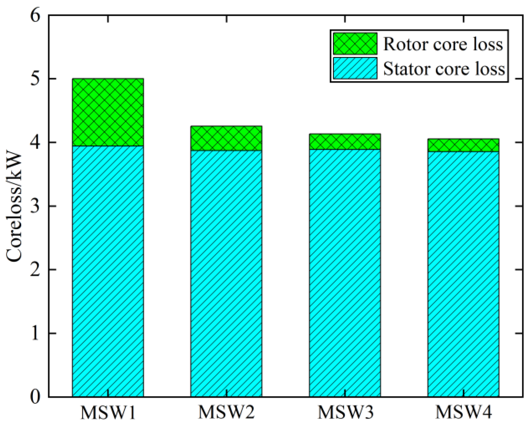
When MSWs with different relative permeabilities are applied to the motor, the motor is directly connected to the power grid and the load remains constant. The influence of different MSWs on the motor core loss was obtained using the finite element method, as shown in Figure 6. From Figure 6, it can be concluded that stator core loss did not change significantly after applying different MSWs. The rotor core loss was relatively large when no MSW was applied, and it decreased significantly after applying MSWs. Moreover, as the relative permeability of the MSW gradually increased, the decrease in rotor core loss was no longer obvious. Therefore, the application of MSWs can reduce rotor core loss, but when the relative permeability of the MSW is 10 and 15, the difference in loss between the two is not significant, so there is no value in pursuing a very high relative permeability of MSW.
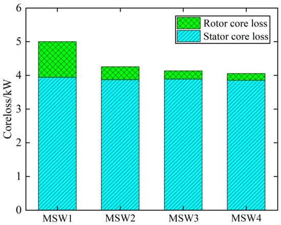
Figure 6.
Comparison of iron loss under different MSWs.
2.3. The Influence of MSW on Copper Loss
Core loss of the motor and copper loss of the winding are important factors affecting the temperature rise and performance of the motor. The previous section studied the effect of MSW on the core loss, and this section analyzes the effect of MSW on the copper loss. The operating conditions of the motor remained the same as in the previous text. The input voltage remained unchanged, and the load torque and rotational speed remained constant. Since motor copper loss is related to the square of the stator phase current and the motor phase resistance is not affected by an MSW, comparison of the motor copper loss is essentially a comparison of the magnitudes of the motor phase currents.
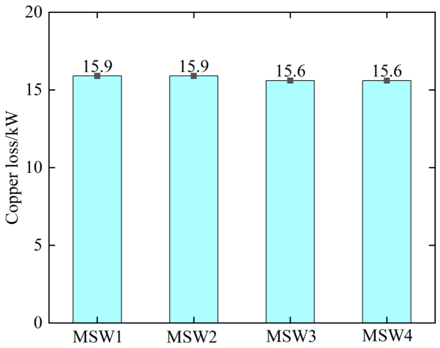
Figure 7 shows the comparison of the motor copper loss under different MSWs. From Figure 7, it can be seen that motor copper loss does not change significantly after applying different MSWs, indicating that the magnitude of the motor phase current is consistent under the four MSW conditions. For LSPMSM, applying MSWs at the same load state will not change the motor copper loss. Therefore, using MSWs in the motor cannot significantly reduce copper loss.
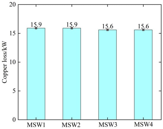
Figure 7.
Comparison of copper loss under different MSWs.
By comparing the core loss of the motor and the copper loss, it is found that MSW can effectively reduce rotor core loss of the motor. The fundamental reason for this is weakening of the amplitude of high-frequency harmonic magnetic fields. However, as can be seen from Figure 6, rotor core loss values are smaller than those of stator core loss. Therefore, the ability of MSW to reduce core loss becomes smaller as the relative permeability increases. Nevertheless, as analyzed in the following section, an increase in the relative permeability of an MSW will increase its detachment risk, which is not conducive to the safe operation of the motor.
3. Motor Reliability
From the previous analysis, it can be concluded that the use of MSWs in LSPMSM can reduce the rotor core loss of the motor, thereby improving the motor efficiency. Compared to epoxy resin slot wedges, an MSW will be subject to the pull force in the air gap, resulting in a greater risk of its fall-off, and subsequently leading to the phenomenon of the motor’s MSW rubbing against the rotor, which affects the safe operation of the motor. Therefore, the risk of fall-off of an MSW is an important factor restricting its use in motors.
The fall-off process of an MSW is roughly as follows. First, under the radial fluctuating force, the edge bevels of the slot wedge are worn narrow and flat, causing one end of the slot wedge to first detach from the stator core and rub against the rotating rotor until the entire slot wedge completely detaches. During the friction process, magnetic powder adheres to the windings and the core, reducing the insulation performance of the windings and, in severe cases, causing short-circuit accidents. The reliability issues of MSWs can be divided into two major categories: mechanical problems and thermal problems. The thermal problem is the corrosion and aging of adhesives in the MSW, and the mechanical problem is force issues of the MSW.
The destructive forces on MSWs mainly include three types:
- (1)
- The magnetic pull exerted by the rotor magnetic field on the MSW, which is essentially Maxwell stress;
- (2)
- The Ampere force resulting from the induced current and magnetic field within the MSW;
- (3)
- The mechanical vibration force at the top of the stator core teeth.
Maxwell stress is the normal force that exists at the interface when a magnetic field passes through two materials with different relative permeabilities. The stress points towards the air gap between the stator and rotor that is in contact with the MSW. Ampere force is the induced eddy current in the MSW under the action of an alternating magnetic field or the transverse current passing through the slot wedge and the silicon steel sheet magnetic circuit that interacts with the air gap magnetic field. Mechanical vibration force is the radial magnetic pull force generated by the air gap magnetic field of the motor on the stator core, which causes periodic mechanical vibration at the top of the core teeth and is transmitted to the MSW. To study the mechanical properties of the MSW, the Maxwell stress and Ampere force acting on the MSW were respectively investigated. However, the magnitude of the mechanical vibration force depends on the manufacturing process level, and the force magnitude varies greatly. This was not analyzed or studied in this paper.
3.1. Maxwell Stress F
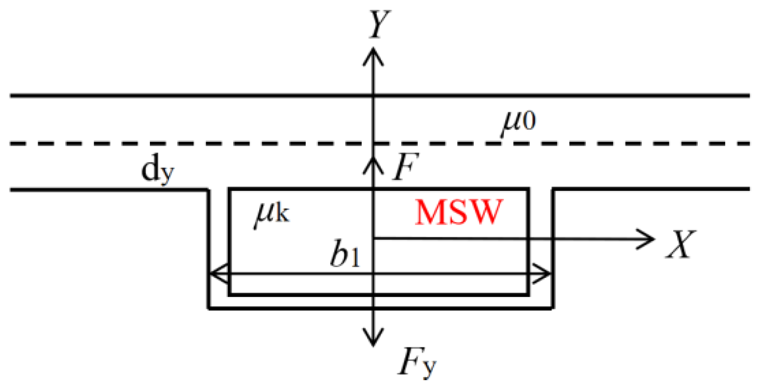
The schematic diagram of Maxwell stress acting on the MSW is shown in Figure 8. The stress direction points towards the side with relatively less magnetic conductivity. Since the magnetic field lines are perpendicular to the interface, the tangential direction (i.e., the X direction) has no component. Assuming that the magnetic flux inside the stator slot is zero, the force Fy is also zero.
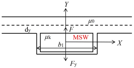
Figure 8.
Diagram of Maxwell stress.
Under the action of the fundamental component of the magnetic field, the Maxwell stress acting on the MSW is F. Assuming that the width of the stator slot is much smaller than the pole pitch, the maximum magnetic density under the slot wedge is equal to the air-gap magnetic density Bδ. The expression for the time-dependent function of the magnetic density distribution on the surface of the magnetic slot wedge is:
where B(t) represents the function of the magnetic flux density in the slot gap varying with time. The relationship between the magnetic energy density w(t) in the gap and time is:
where, μ0 represents the vacuum permeability, and its numerical value is 4π × 10−7 H/m.
The relationship between the internal magnetic field energy density wMSW(t) of the magnetic wedge and time is:
where μk represents the magnetic permeability of the MSW, and μr represents the relative permeability of the MSW.
When the wedge moves a distance of dy, the magnetic energy of the air gap changes to dW:
In the formula, the volume of the MSW is dV = b1ldy, where b1 and l represent the width and length of the MSW, respectively. Substituting the above formula yields the expression for dW as follows:
When the MSW moves a small distance dy into the air gap, the work done by Maxwell stress F is dA = Fdy. According to the law of conservation of energy
the function describing the variation of stress F over time is derived as follows:
dA = dW,
After simplification, F is
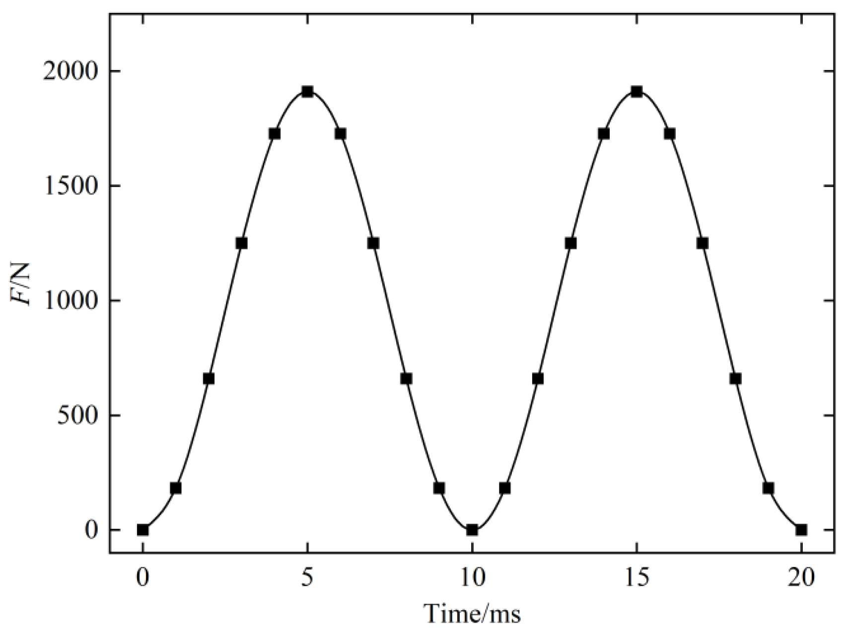
In this paper, Bδ, b1, l, μr, and ω are 0.8 T, 0.014 m, 0.67 m, 5, and 100π, respectively. The stress F waveform obtained is shown in Figure 9. At the same time, according to the formula, it can be found that the stress F is a periodic pulsating force with a period frequency that is twice the angular frequency. In the example, the power supply frequency is 50 Hz.
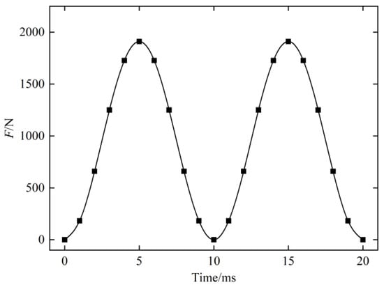
Figure 9.
Maxwell stress F waveform.
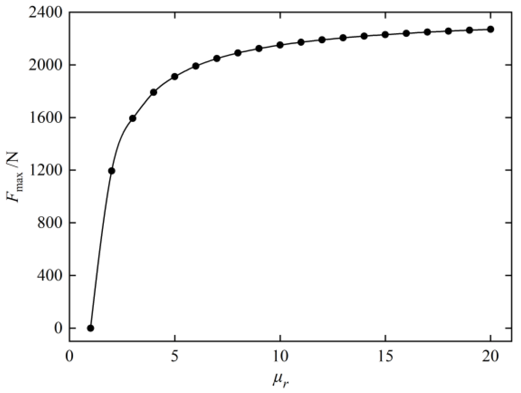
Regardless of whether a high relative permeability MSW is used, there exists a theoretical maximum value for the Maxwell stress. When the width and length of the MSW is determined, the expression for the maximum Fmax is:
The maximum Maxwell stress exerted on MSWs with different relative permeability was analyzed, as shown in Figure 10. When the relative permeability of the MSW increased from 1 to 5, the Fmax exerted on the slot wedge itself increased rapidly. As the relative permeability of the MSW continued to increase, Fmax tended to stabilize.
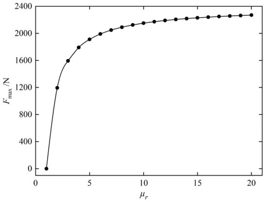
Figure 10.
The variation in Fmax with MSW permeability.
3.2. Ampere Force Fe
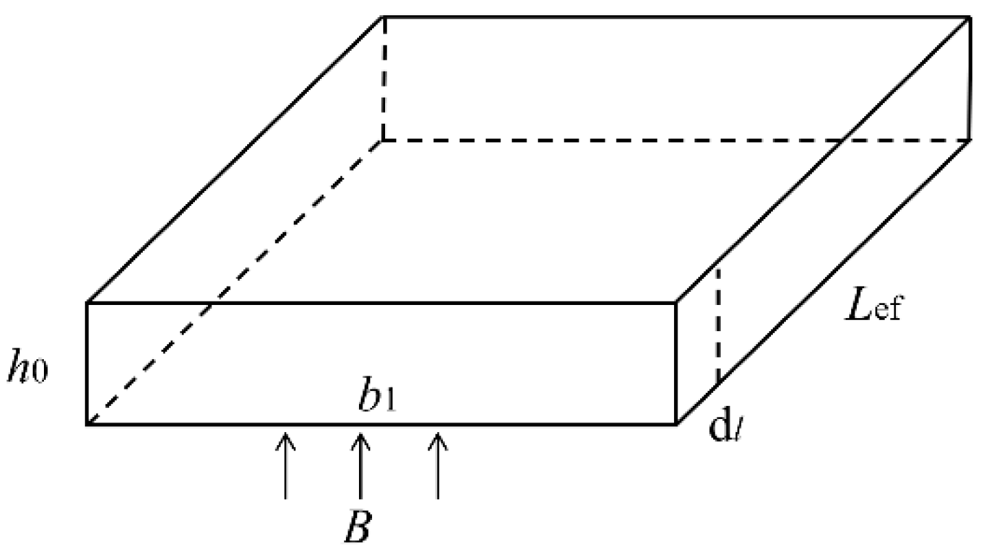
The internal current of the MSW interacts with the magnetic field of the air gap, and the interaction force between them is the Ampere force Fe, Fe = BIL. B is the magnetic density of the air gap, which is assumed to be the same as Equation (12). L is the axial length of the MSW; when the MSW is not segmented, it is the length of the core. I is the current induced in the MSW, and calculation of the electromagnetic force mainly involves calculation of the induced current. The equivalent schematic diagram of the induced current in the MSW is shown in Figure 11. The alternating magnetic flux induces eddy currents in the conductive slot wedge.
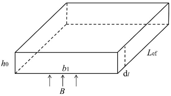
Figure 11.
Induced current model in MSW.
The magnetic flux variation inside the MSW is:
From the law of electromagnetic induction and the resistance calculation formula,
where ρ represents the resistivity of the MSW material, and h0 is the height of the slot wedge. According to Ohm’s law, the current can be expressed as:
Lef represents the axial length of the slot wedge. When the slot wedge is not segmented, this is the same as the length of the stator core. After reorganization, the Ampere force Fe can be expressed as:
From Equation (27), it can be seen that Fe varies with time at a double-frequency rate. Compared with Maxwell stress F, Fe does not have a direct current component. The average value of the force within one cycle is zero, but the existence of Fe will increase the overall force amplitude of the MSW. Considering the actual resistivity range of the MSWs, which is 106 to 1010 Ω·mm2/m, the above Maxwell stress calculation case is still adopted. The numerical range of Fe is 10−7 to 10−11 N. Therefore, due to its own high resistivity characteristic, the Ampere force Fe acting on the MSW can be ignored and it is only subjected to stress.
3.3. Simulation Analysis
Based on the previous theoretical analysis, it was concluded that the MSW only experiences Maxwell stress F. In the previous text, to simplify the analysis of stress, the rotor magnetic field was assumed to be sinusoidal. Therefore, the magnetic force waveform was a sine wave. However, the actual radial air gap magnetic field waveform is a flat-top wave, which contains not only the fundamental component but also other harmonic components. In order to accurately obtain the Maxwell stress waveform of the MSW and verify the previous theoretical analysis, this section continued to use Ansys finite element software to calculate the Maxwell stress waveform.
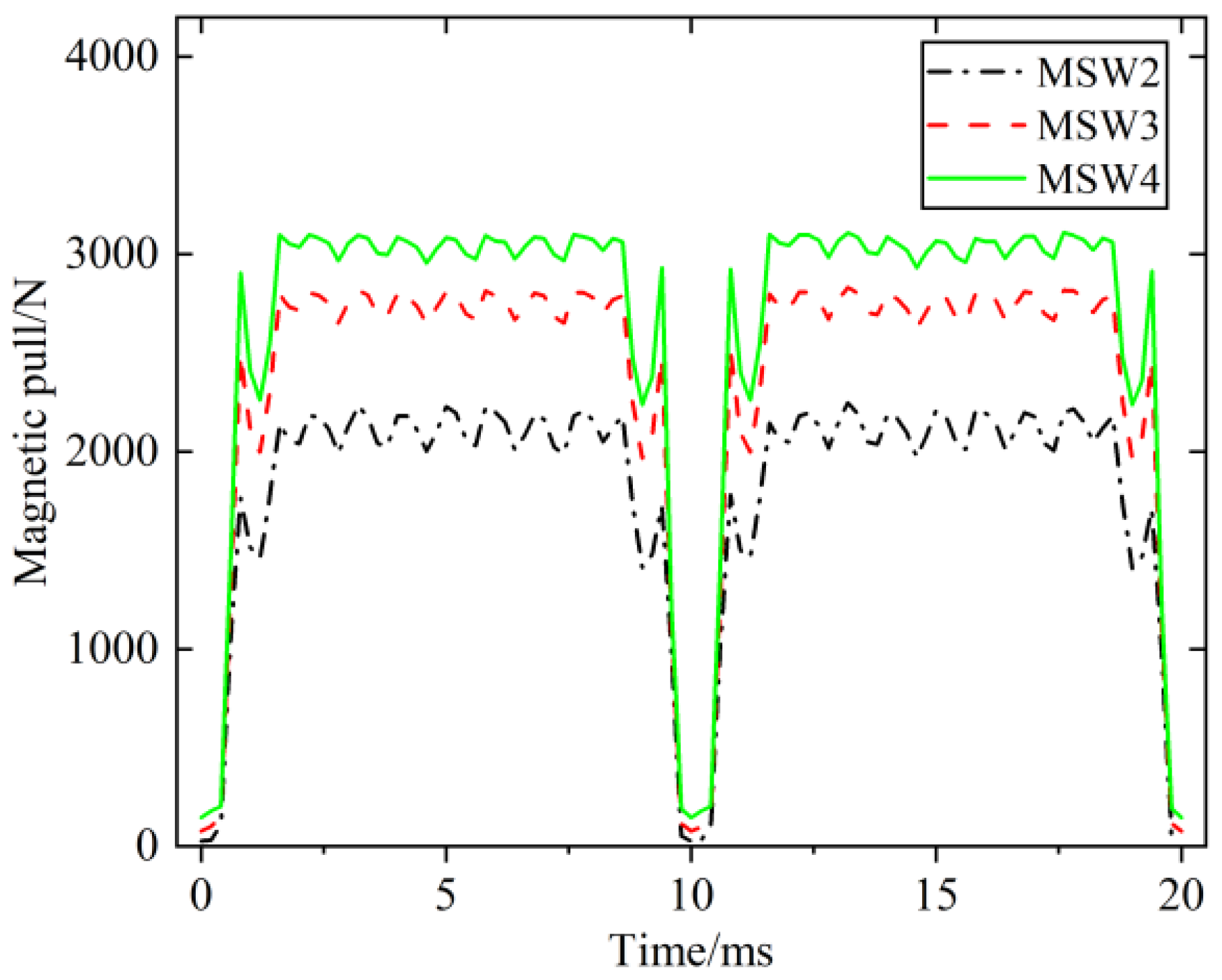
Figure 12 shows the comparison of the F waveforms of MSWs with different relative permeabilities. From the F waveforms in the figure, it can be seen that the period is the same as that analyzed in the previous text, with a period frequency of 100 Hz, indicating the correctness of the theoretical analysis. However, the change in relative permeability only causes the magnitude of the magnetic force to change, and the fluctuation of F does not make a significant difference.
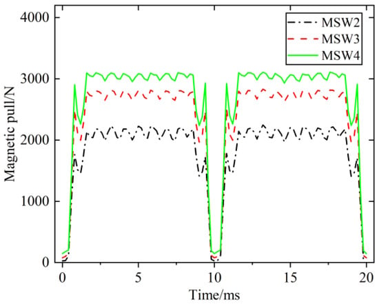
Figure 12.
Magnetic stress F waveform.
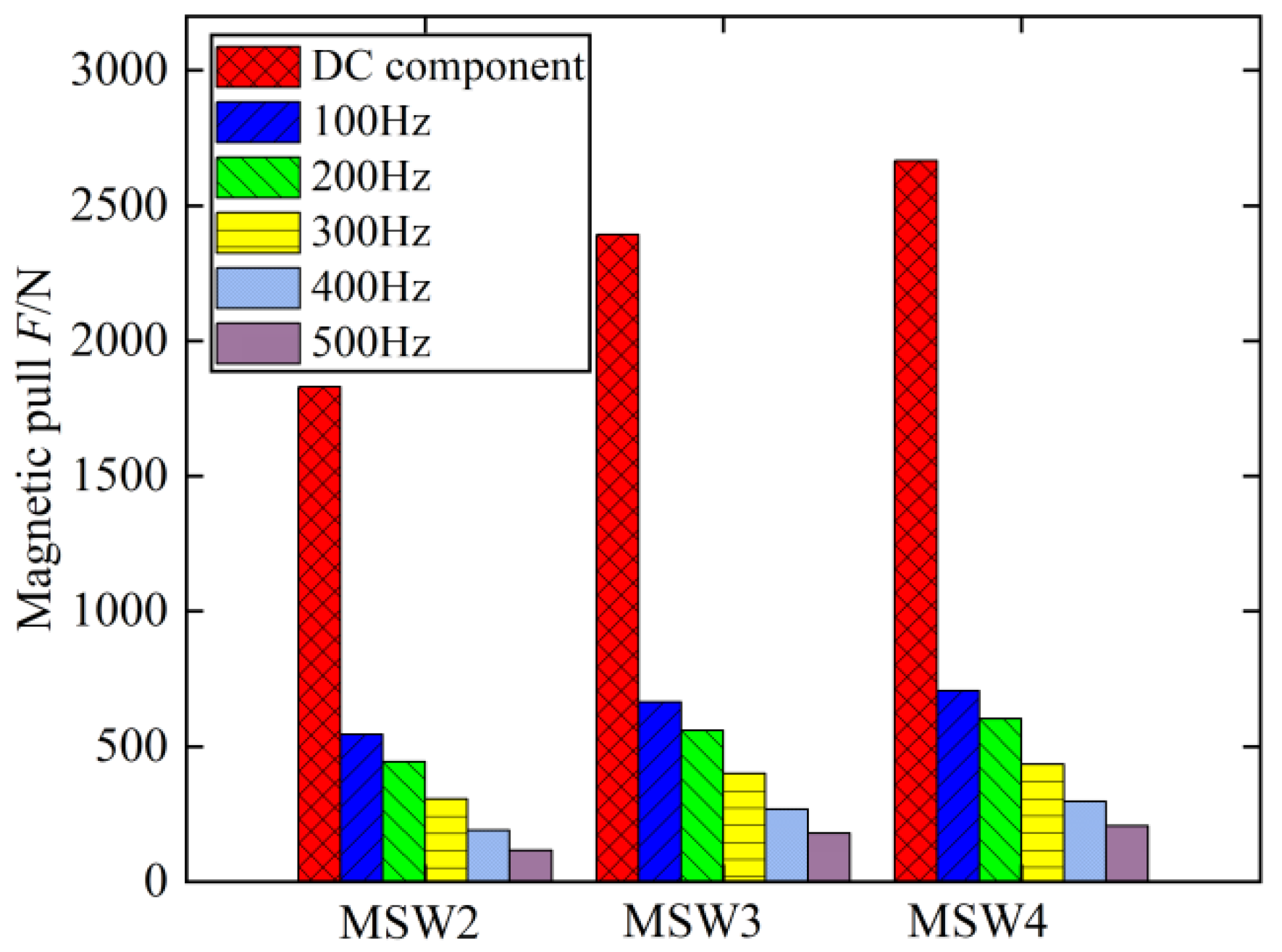
Fourier analysis of the F wave of the MSWs is shown in Figure 13. Comparing the three types of MSW, it is found that the DC component of F increases significantly with the increase in relative permeability, while the AC component of the magnetic force increases slightly with the increase in relative permeability. The magnetic force AC component acting on the stator slot of the MSW repeatedly pulls and drags, and long-term friction with the stator core will cause damage to the edge of MSW and eventually detachment. Therefore, the AC component of F should be prevented. Combining Figure 10 and Figure 12, it can be seen that the change in magnetic force does not depend linearly on the relative permeability of the MSW. The AC component of the magnetic force is smaller and the risk of detachment is lower within the range of relative permeability from 5 to 10.
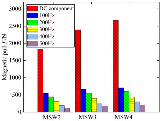
Figure 13.
Magnetic stress F waveform decomposition.
3.4. Mechanical Strength
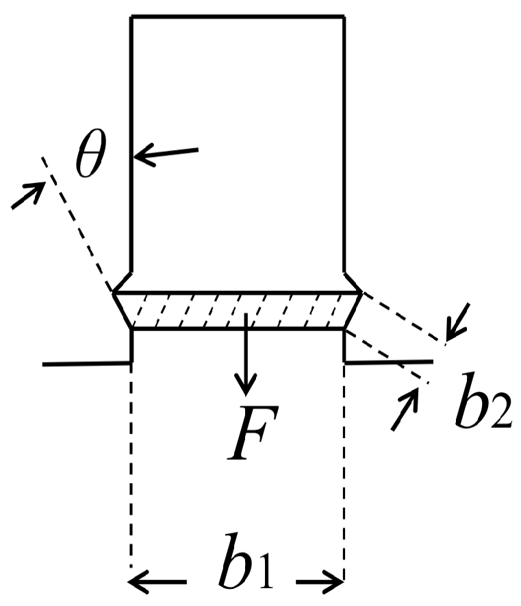
The main force acting on the magnetic slot wedge is magnetic pull force. Figure 14 shows the actual size of the magnetic slot wedge in the motor. In the figure, F represents the Maxwell stress, b1 is the contact width between the slot wedge and the air gap magnetic field, b2 is the contact width between the slot wedge and the root of the stator teeth, and the left and right sides of the magnetic slot wedge, respectively, contact the top of the stator teeth.
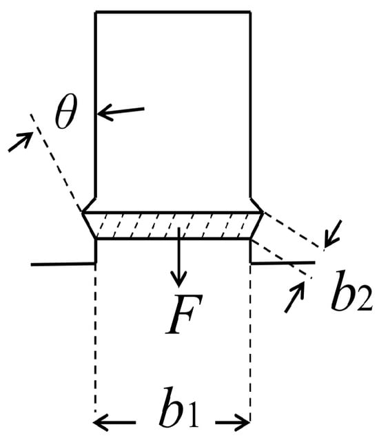
Figure 14.
Strength analysis of MSW.
The stress intensity at the contact point between the wedge and the top of the stator teeth is:
σ represents the stress intensity, while F and S denote the pulling force and contact area, respectively, that the magnetic slot wedge is subjected to. By substituting the expression for the maximum magnetic pulling force (21) and performing rearrangement, we obtain:
In this case, the b2sin(θ) value of the magnetic wedge is 1.05 mm. After calculation, the yield strength of the MSW is 1.43 Mpa. According to the literature, the yield strength of existing magnetic wedges is in the range of 150 to 250 Mpa.
4. Prototype Manufacturing and Experimental Testing
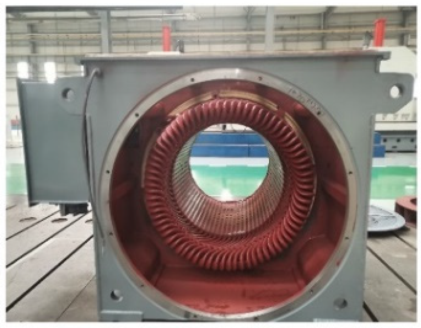
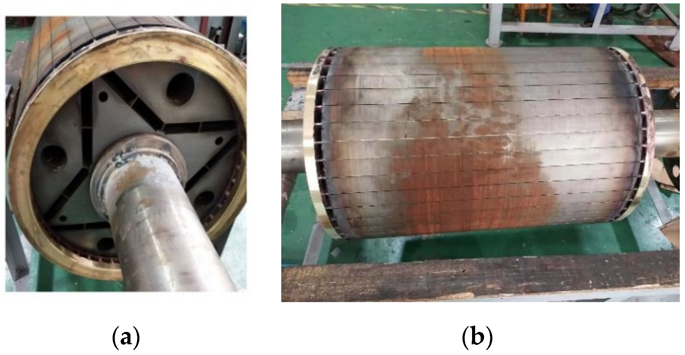
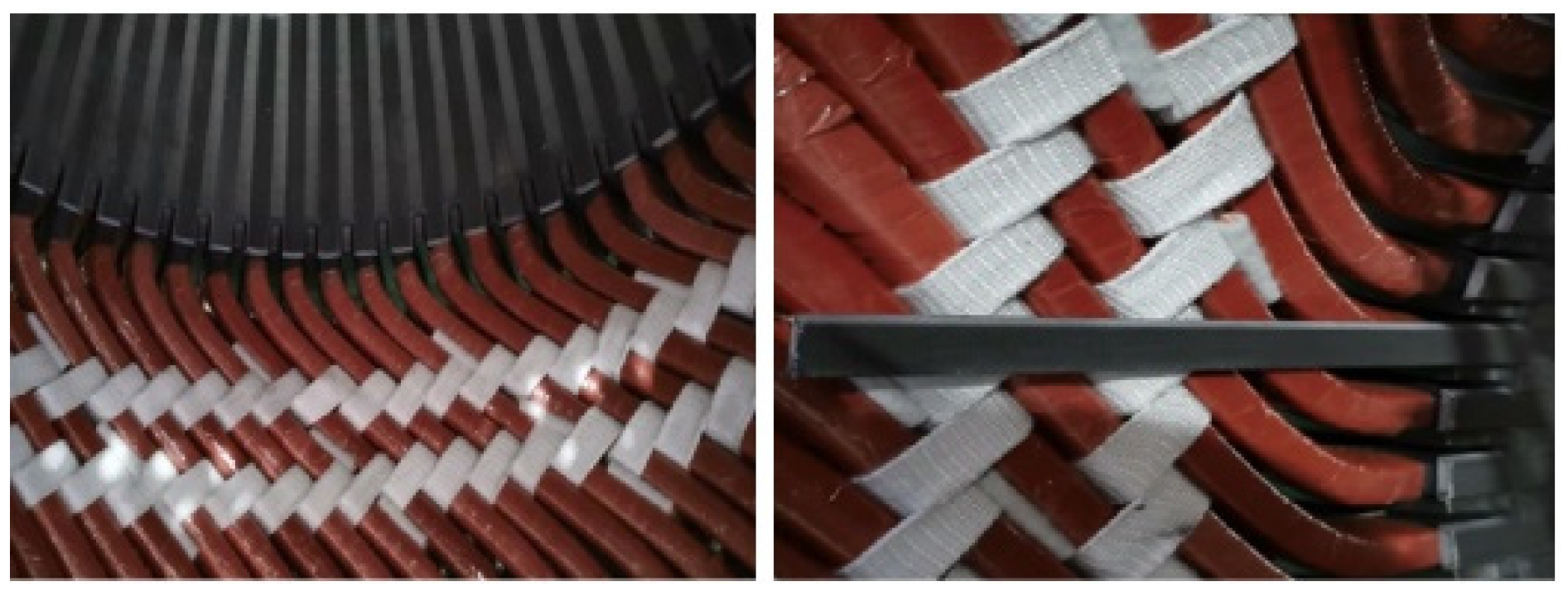
In order to verify the impact of MSWs on the motor performance, a LSPMSM prototype was manufactured according to the data in Table 1. The stator structure is shown in Figure 15, and the rotor structure is shown in Figure 16 (front view and side view), respectively. Figure 17 shows that the MSWs were inserted into the slots of the stator core. Considering the axial length of the motor (670 mm) and the axial mechanical strength of the MSW, each MSW was divided into several parts and inserted into the motor interior along the axial direction.
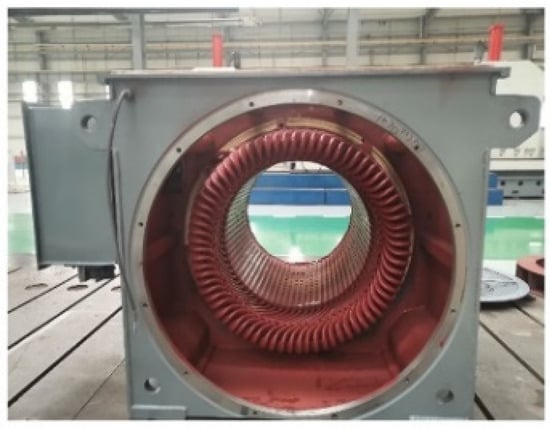
Figure 15.
Stator structure.
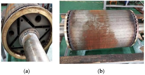
Figure 16.
Rotor structure: (a) Rotor; (b) Top view of rotor [18].
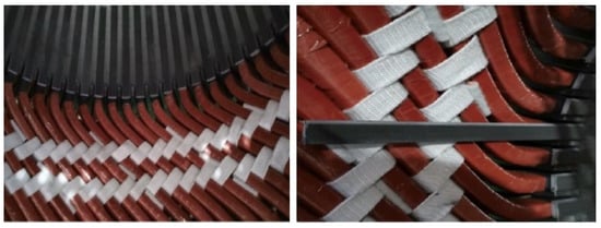
Figure 17.
MSW and stator core [18].
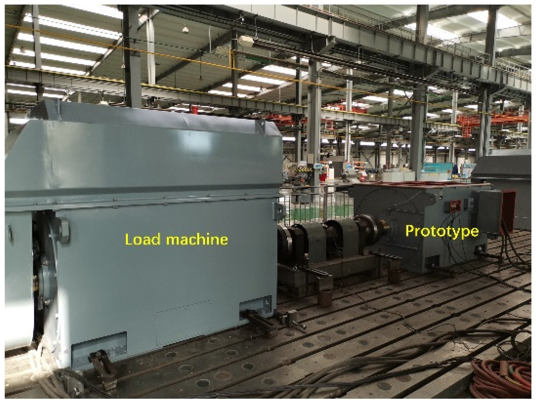
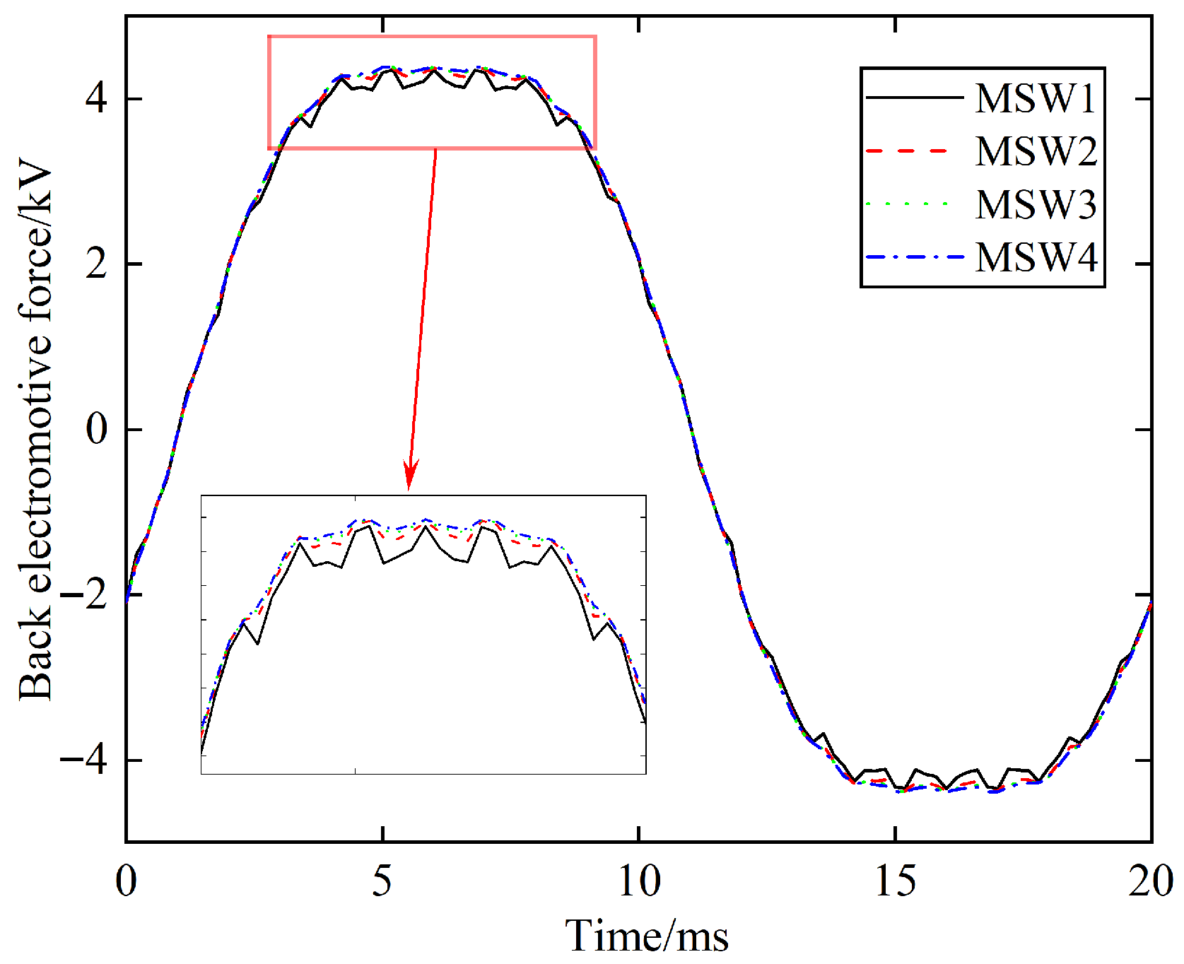
The motor driving test platform is shown in Figure 18. By testing without installing the MSW model MSW1 or other MSWs, the no-load back EMF waveform of the motor was measured using a power analyzer. The overall no-load back EMF waveform as shown in Figure 19 reveals that the waveform did not significantly change with the material characteristics of the MSW. However, by zooming in on the local section, it can be clearly seen that at the peak positions of the waveform, the MSWs significantly suppressed the vibration at the peak. The reason for this phenomenon is that the MSWs effectively weaken the modulation ability of the stator slot holes on the rotor magnetic flux, thereby reducing the amplitude of the tooth harmonic magnetic field. Therefore, it is verified that the MSWs suppress the rotor core loss.
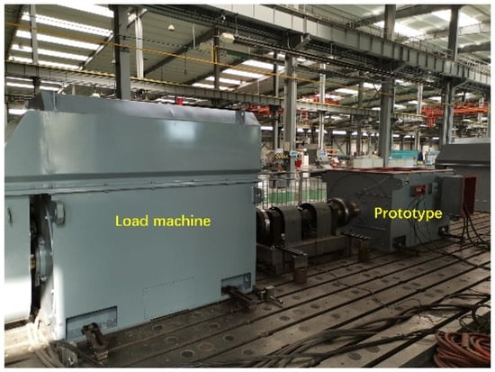
Figure 18.
Experimental test [18].
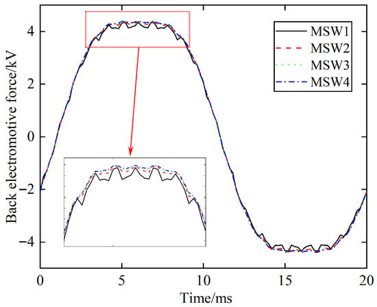
Figure 19.
Back EMF waveforms.
5. Discussion
In this paper, we concluded that the higher the relative permeability value of an MSW, the better the attenuation of the harmonic magnetic field amplitude in the teeth. However, based on the references and analysis of the Maxwell stress F, it is found that a higher relative permeability value will lead to an increase in the leakage reactance of the stator slots and the Maxwell stress F of the motor. The drawbacks of conventional MSWs is that their own magnetic permeability is isotropic. If the MSW is anisotropic, the leakage reactance of the stator slot will be reduced. Therefore, in future research, the anisotropy of the MSW will be the main research target, while also considering the attenuation of the harmonic.
6. Conclusions
In this paper, the influence of the relative permeability value of an MSW on the air-gap magnetic waveform, core loss, copper loss, Maxwell stress F and Ampere force Fe of an LSPMSM was studied. It was concluded that the influence of the MSW on the core loss of the LSPMSM is mainly on rotor core loss.
The electromagnetic force that the MSW receives during motor operation is only the Maxwell stress F component, and there is no Ampere force Fe component. Through the decomposition of the Maxwell stress F waveform, it can be known that change in the relative permeability of an MSW only has a significant effect on the DC component of F, but has a relatively small effect on the AC component. However, the AC component of the Maxwell stress F is the main reason for the detachment of MSWs. Through experiments, the weakening effect of MSWs on the modulation of stator slots was verified. Through the research of the entire paper, it is recommended to adopt a relative MSW permeability value within the range from 5 to 10, which can achieve weakening of the amplitude of the harmonic magnetic field of the teeth without increasing the Maxwell stress received by the MSW.
Author Contributions
Conceptualization, D.L. and X.C.; methodology, S.W.; software (AnsysEM2021), P.C.; validation, D.L., D.P. and J.W.; formal analysis, D.L.; investigation, P.C.; resources, J.W.; data curation, S.W.; writing—original draft preparation, D.L.; writing—review and editing, D.L.; visualization, D.L.; supervision, X.C.; project administration, S.W.; funding acquisition, D.L. All authors have read and agreed to the published version of the manuscript.
Funding
This research was funded by Basic Research Project for Universities of Liaoning Provincial Education Department, grant number LJ212511632005.
Data Availability Statement
The original contributions presented in this study are included in the article. Further inquiries can be directed to the corresponding author.
Conflicts of Interest
The authors declare no conflicts of interest.
Abbreviations
| LSPMSM | Line Start Permanent Magnet Synchronous Motor |
| MSW | Magnetic Slot Wedge |
References
- Hu, Y.; Chen, B.; Xiao, Y.; Shi, J.; Li, L. Study on the Influence of Design and Optimization of Rotor Bars on Parameters of a Line-Start Synchronous Reluctance Motor. IEEE Trans. Ind. Appl. 2020, 56, 1368–1376. [Google Scholar] [CrossRef]
- Sarac, V.; Minovski, D.; Janiga, P. Parametric Analysis for Performance Optimization of Line-Start Synchronous Motor with Interior Asymmetric Permanent Magnet Array Rotor Topology. Electronics 2022, 11, 531. [Google Scholar] [CrossRef]
- Lin, M.; Li, D.; Ren, X.; Han, X.; Qu, R. Line-Start Vernier Permanent Magnet Machines. IEEE Trans. Ind. Electron. 2021, 68, 3707–3718. [Google Scholar] [CrossRef]
- Li, D.; Feng, G.; Li, W.; Zhang, B.; Xu, Y.; Chen, Y.; Zheng, J.; Wu, Q. Irreversible Demagnetization of a Large Capacity Line-Start Permanent Magnet Synchronous Motors Considering Influence of Permanent Magnet Temperature. Int. Trans. Electr. Energy Syst. 2023, 2023, 6798493. [Google Scholar] [CrossRef]
- Baka, S.; Sashidhar, S.; Fernandes, B.G. Design of an Energy Efficient Line-Start Two-Pole Ferrite Assisted Synchronous Reluctance Motor for Water Pumps. IEEE Trans. Energy Convers. 2021, 36, 961–970. [Google Scholar] [CrossRef]
- Yan, B.; Yang, Y.; Wang, X. Design of a Large Capacity Line-Start Permanent Magnet Synchronous Motor Equipped with Hybrid Salient Rotor. IEEE Trans. Ind. Electron. 2021, 68, 6662–6671. [Google Scholar] [CrossRef]
- Rabbi, S.F.; Rahman, M.A. Critical Criteria for Successful Synchronization of Line-Start IPM Motors. IEEE J. Emerg. Sel. Top. Power Electron. 2014, 2, 348–358. [Google Scholar] [CrossRef]
- Sundaram, J.; Karpagam, R. A New Wedge Shaped Inner Rotor for a BLDC Motor: Performance Analysis. Therm. Sci. Eng. Prog. 2024, 54, 102863. [Google Scholar] [CrossRef]
- Frosini, L.; Pastura, M. Analysis and Design of Innovative Magnetic Wedges for High Efficiency Permanent Magnet Synchronous Machines. Energies 2020, 13, 255. [Google Scholar] [CrossRef]
- De Donato, G.; Capponi, F.G.; Caricchi, F. No-Load Performance of Axial Flux Permanent Magnet Machines Mounting Magnetic Wedges. IEEE Trans. Ind. Electron. 2012, 59, 3768–3779. [Google Scholar] [CrossRef]
- De Donato, G.; Giulii Capponi, F.; Caricchi, F. On the Use of Magnetic Wedges in Axial Flux Permanent Magnet Machines. IEEE Trans. Ind. Electron. 2013, 60, 4831–4840. [Google Scholar] [CrossRef]
- Qiu, H.; Xu, Y.; Liu, Y.; Sun, J.; Yang, C. Influence of Magnetic Slot Wedge on the Performance of 10-kV, 1000-kW Permanent Magnet Synchronous Motor. Int. Trans. Electr. Energy Syst. 2020, 30, e12332. [Google Scholar] [CrossRef]
- Wang, S.; Zhao, Z.; Yuan, L.; Wang, B. Investigation and Analysis of the Influence of Magnetic Wedges on High Voltage Motors Performance. In Proceedings of the 2008 IEEE Vehicle Power and Propulsion Conference, Harbin, China, 3–5 September 2008; pp. 1–6. [Google Scholar]
- Mikami, H.; Ide, K.; Arai, K.; Takahashi, M.; Kajiwara, K. Dynamic Harmonic Field Analysis of a Cage Type Induction Motor When Magnetic Slot Wedges Are Applied. IEEE Trans. Energy Convers. 1997, 12, 337–343. [Google Scholar] [CrossRef]
- Liu, Z.; Wang, X.; Du, B.; Xu, X.; Ji, S.; Xiao, C. Performance Optimization Analysis of PMLSM with Novel Composite Magnetic Slot Wedge. In Proceedings of the 2019 22nd International Conference on Electrical Machines and Systems, Harbin, China, 11–14 August 2019; pp. 1–4. [Google Scholar]
- ABB’s True NEMA Modular Induction Machine. Available online: https://new.abb.com/motors-generators/AMI5800 (accessed on 18 October 2025).
- Uzhegov, N.; Pihlajamäki, A.; Nerg, J.; Pyrhönen, J. Magnetic Wedges in a Steam-Resistant Electrical Machine Insulation System. IEEE Trans. Dielect. Electr. Insul. 2015, 22, 3153–3162. [Google Scholar] [CrossRef]
- Li, D.; Feng, G.; Li, W.; Zhang, B.; Zhang, J. Effect of Stator Slots on Electromagnetic Performance of a High-Voltage Line-Start Permanent Magnet Synchronous Motor. Energies 2022, 15, 3358. [Google Scholar] [CrossRef]
Disclaimer/Publisher’s Note: The statements, opinions and data contained in all publications are solely those of the individual author(s) and contributor(s) and not of MDPI and/or the editor(s). MDPI and/or the editor(s) disclaim responsibility for any injury to people or property resulting from any ideas, methods, instructions or products referred to in the content. |
© 2025 by the authors. Licensee MDPI, Basel, Switzerland. This article is an open access article distributed under the terms and conditions of the Creative Commons Attribution (CC BY) license (https://creativecommons.org/licenses/by/4.0/).

