Abstract
Phase-change materials (PCMs) are integral to the thermal energy storage devices used in phase-change storage air-conditioning systems, but their adoption is hindered by slow heat transfer rates and suboptimal energy storage efficiency. In this study, we design and analyze a flat-panel thermal energy storage device based on PCM, using both numerical simulations and experimental testing to evaluate performance under various operating conditions. The simulations, conducted using computational fluid dynamics (CFD) in a steady-state environment with an inlet temperature of 12 °C, demonstrate that the phase-change completion time for cooling storage is 8331 s, while the cooling release process is completed in 3883 s. The fluid distribution within the device is found to be uniform, and the positioning of the inlet and outlet has a minimal effect on performance metrics. However, the lateral stacking configuration of PCM units significantly improves heat transfer efficiency, increasing it by 15% compared to vertical stacking arrangements. Experimental tests confirm that increasing the inlet flow rate accelerates the phase transition process but has a marginal impact on overall energy utilization efficiency. These results provide valuable quantitative insights into optimizing the design of phase-change thermal storage devices, particularly in terms of enhancing heat transfer and overall energy efficiency.
1. Introduction
With the intensification of global warming, additional measures are needed to deal with extreme climate changes and ensure a healthy and comfortable indoor environment for residents. The growing annual rise in energy usage for building climate control systems has exacerbated the disparity between electricity supply and demand [1]. In particular, there is a significant difference in the utilization rate of peak-valley power in China, and the power peak load capacity is insufficient, which poses a threat to grid stability and energy security [2]. Notably, during summer peaks, cooling systems contribute over 30% of total building energy consumption [3]. Phase-change energy storage air-conditioning technology plays a role in promoting power load peaking and valley filling, with features such as a simple system structure, high energy storage density, and efficient system operation efficiency; as such, it offers a promising solution for balancing energy supply–demand mismatches and optimizing grid load management [4,5,6].
Thermal energy storage (TES) systems can be categorized into three main types: chemical energy storage, potential energy storage, and sensible energy storage [7]. Chemical energy storage involves the use of chemical reactions to store and release heat. Apparent energy storage is the most common type of thermal energy storage, in which a substance is heated and its thermal energy is stored, and the temperature of the stored substance is increased without a phase change of the substance. Phase-change materials (PCM) store thermal energy through the phase change of a substance between solid and liquid states. The advantage of phase-change materials is that they are capable of storing and releasing large amounts of heat during the phase-change process, and they therefore have a high energy density. By combining phase-change energy storage with air-conditioning systems, not only can we achieve efficient heat storage and release, but we can also improve the energy efficiency and reliability of the system. Compared to traditional tank energy storage technology, phase-change energy storage offers higher energy density, more flexible temperature control performance and more compact design, making it suitable for a variety of environments that require stable temperature regulation [8].
As a key component of air-conditioning technology with phase-change energy storage, the core component of such systems directly influences their overall performance [9]. Current designs include cylindrical, shell-and-tube, and rectangular configurations [10]. The flat-panel phase-change energy storage device composed of parallel phase-change material (PCM) plates, in which heat transfer fluid (HTF) flows between two adjacent PCM plates, has gained attention due to its streamlined geometry and enhanced surface-to-volume ratios [11]. At present, two major challenges hinder the application of these devices: the first is the development of transient models to track dynamic solid–liquid interfaces during phase transitions; the second is the structure of flat-panel phase-change energy storage devices, which affects the performance of the device and needs to be optimized and improve the utilization of heat energy [12]. Iten et al. [13] established two computational fluid dynamics (CFD) models using the enthalpy method and effective heat capacity method to simulate air thermal energy storage (TES) devices, validating predictions against experimental outcomes. Halawa et al. [14] discussed melting/freezing dynamics in PCM plates under airflow, correlating numerical results with heat transfer rates. Crespo et al. [15] optimized slab configurations in PCM tanks using finite-volume simulations, while Nie et al. [16] explored paraffin-based systems to assess thermal conductivity and fin designs. Younis et al. [17] compared geometric variations (e.g., sinusoidal, triangular) to reduce PCM melting times, noting trade-offs between heat transfer enhancement and reduced storage capacity. Huang et al. [18] linked flow rates to thermal stratification via dimensionless parameters. Ye et al. [19] simulated fluid flowing and heat transfer phenomena in phase-change units with different cavity volume fractions of PCM. Xie et al. [20] discussed the effect of the aspect ratio on the melting of PCM in cavity vessels with fixed power and proposed a differential liquid fraction curve along with solid–liquid interface evolution to reveal the melting rate and typical phase-change characteristics.
Hari et al. [21] developed a nano-enhanced activated biochar composite phase-change material (PCM) by adding activated biochar with graphene, which significantly enhances the thermal conductivity and solves the problem of 1-tetradecanol PCM’s leakage and metal corrosion. Prabhu et al. [22] reported for the first time a composite paraffin phase-change material (CPN) based on carbonized shell–shell porous carbon (CSC), which achieves leakage resistance, thermal conductivity multiplication and high thermal stability through an optimized ratio, providing an efficient and long-lasting thermal storage solution for PV cooling systems. Homlakorn et al. [23] designed a PCM storage and cooling vessel with integrated fins and a metal mesh structure to achieve efficient cooling of PV panels by reducing conduction resistance. Chang et al. [24] has identified new low eutectic phase-change materials (EPCMs) designed with fatty acid/paraffin composites, whose adjustable melting point and high latent heat properties significantly improve the thermal management performance of electronic devices, providing a precise temperature control solution for high-power electronic devices.
HDPE has a high melting point (approx. 135 °C) and corresponding thermal energy storage (up to 240 J/g), making it ideal for medium-temperature thermal energy storage. Based on its excellent thermal energy storage properties, HDPE is able to effectively store and release heat, making it particularly suitable for applications such as low-grade waste heat recovery and solar thermal energy storage.
Zhu et al. [25] objectively evaluated the application of composite phase-change materials (CPCM) using high-density polyethylene (HDPE) storage to improve thermal properties such as thermal storage capacity and thermal conductivity. HDPE using a continuous hot melt extrusion production process is effective on a laboratory scale and has the potential for large-scale production; it shows good stability after 100 thermal cycles, which suggests a longer storage life. Weingrill et al. [26] explore the thermo-oxidative stability and ageing of high-density polyethylene (HDPE) as a phase-change material (PCM), simulating real-world conditions of use and assessing the potential of HDPE for long-term thermal energy storage. With only a slight loss of storage capacity after prolonged exposure to elevated temperatures (160 °C and 180 °C) for up to 7200 h, HDPE demonstrates good long-term stability and low costs, high availability, and minimal degradation under oxidizing conditions.
Existing studies predominantly focus on how the structural parameters of flat-panel phase-change energy storage units affect heat transfer and operational efficiency, yet there remains a need for a holistic evaluation of system-wide performance during practical operations. Consequently, deeper investigations into real-world behavioral shifts in phase-change thermal storage devices are essential to enhance their efficacy in climate-control applications.
Employing an enthalpy-based methodology, a computational fluid dynamics framework was developed to simulate and refine the performance of panel-based thermal storage units. Numerical analyses were employed to examine the effects of inlet positioning, operational parameters, and stacking orientations (horizontal/vertical) on overall system functionality, offering foundational insights for design enhancements. Furthermore, experimental measurements were carried out. Guided by numerical simulations of the panel-based thermal storage module, a dedicated experimental platform was built. Through systematic adjustments to operational variables, the integrated performance of the phase-change energy storage unit was evaluated, confirming the reliability of the computational models. Our research can offer experimental data support to facilitate the structural optimization design of the phase-change storage system and the promotion and application of this system.
2. Experimental and Simulation Methods
2.1. Numerical Simulation Method
2.1.1. Physical Model
The advantages and disadvantages of different geometries (e.g., shell-and-tube, cylindrical, and flat-plate structures) were considered in the design of the flat-plate thermal energy storage device. The advantage of flat-plate structures over shell-and-tube or cylindrical structures is that they have a higher surface area/volume ratio, which contributes to higher heat transfer efficiency. Especially in the case of fluid flow between plates of phase-change material (PCM), the flat-plate geometry optimizes the heat exchange process and reduces the resistance to heat transfer. In addition, flat-plate structures are more compact in terms of spatial layout, making them suitable for large-scale thermal energy storage systems. Although shell-and-tube and cylindrical designs also offer some advantages, especially in terms of fluid flow and heat exchange efficiency, the simplicity and cost-effectiveness of the flat-plate design make it the best choice for this study.
In order to explore the internal structure of the flat-panel phase-change energy storage device and the influence on the energy storage/release performance of the different operating conditions of the device, the flat-panel phase-change energy storage device was designed, as illustrated in Figure 1. The unit is composed of a rectangular water tank and horizontally placed PCM plates that are stacked and maintained at a certain gap to act as a heat exchange runner for water. A diffuser is provided at the inlet and outlet of the unit to ensure that the water flow is evenly distributed to the various heat exchange runners.
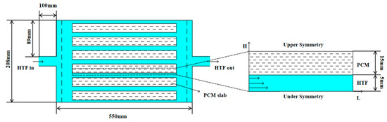
Figure 1.
Physical model of flat-panel phase-change energy storage device and phase-change energy storage unit.
Considering the uniformity of horizontal flow patterns perpendicular to the flow direction, the model was reduced from three-dimensional to two-dimensional geometry. Key simplifying assumptions include:
- (1)
- Uniform mass flow distribution and identical inlet temperatures across all heat transfer fluid (HTF) channels;
- (2)
- Due to the thin and flat physical properties of the plate and the characteristics of its horizontal layout, the natural convection within the liquid phase of PCM is ignored;
- (3)
- The energy loss of the phase-change energy storage device to the environment is not considered;
- (4)
- Homogeneity and isotropy of PCM with constant thermophysical properties;
- (5)
- The initial temperature of all PCM is the same. The initial temperature of the HTF and the container in the device is also the same;
- (6)
- Gravity is vertical, and there is no symmetry in that direction.
The analytical framework omitted natural convection effects within the PCM’s liquid phase, thereby constraining gravitational impacts on heat transfer dynamics. Owing to the layered arrangement of PCM and HTF channels, the computational domain was reduced to a periodic segment comprising alternating HTF and PCM pathways. Simulations evaluated the cooling storage and release performance across varying HTF channel gaps (HHTF = 2 mm, 4 mm, 6 mm, 8 mm, 10 mm) and PCM layer thicknesses (HPCM = 10 mm, 15 mm, 20 mm, 25 mm, 30 mm, 35 mm, 40 mm). This parametric study generated 35 distinct configurations of the plate-type thermal storage unit, enabling a systematic analysis of structural influences on operational behavior.
2.1.2. Mathematical Model
The phase transition dynamics were simulated using a model grounded in the enthalpy–porosity method. This approach introduces the liquid phase ratio β, which quantifies the phase state transition from solid (β = 0) to liquid (β = 1) as a function of temperature [27]:
where and are the solidification temperature and melting point of the PCM, respectively, °C; β is the liquid phase ratio of PCM.
For a single medium = , there is a solid–liquid interface curve during phase change. For a non-single medium, = in general; there is a solid–liquid coexistence zone during phase change, and the liquid phase fraction in this region is 0 < β < 1.
Based on the enthalpy method model, the enthalpy and temperature of PCM are regarded as the variables to be solved at the same time, and a unified conservation equation only needs to be established for the solid-phase region, the paste region and the liquid-phase domain are modeled using unified conservation principles, eliminating the need for distinct governing equations. These formulations adhere to the fundamental laws of momentum balance, energy preservation, and mass continuity. Guided by the established assumptions, the phase transition dynamics of PCM are governed by the following equations [28,29,30]:
where ρ is density, kg·m−3; H is the heat content value of the PCM, kJ·kg−1; h is the sensible heat of PCM, kJ·kg−1; ∆H is the enthalpy of PCM, kJ·kg−1; is the velocity of flow, m·s−1; is the isobaric specific heat capacity, J·kg−1∙K−1; is the reference temperature, K; is the standard enthalpy value, kJ·kg−1; S is the source term, and the difference calculation is performed. μ is the dynamic viscosity, kg∙s·m−2. β is the liquid-phase volume fraction. p is the pressure, Pa.
S in Equation (8) is the source term of momentum equation, representing the loss of momentum, which is specifically expressed as:
where ε is less than 0.0001 to avoid a zero denominator; is the continuous number of the partially solidified region during the phase change. is the implicated velocity, indicating the continuous motion of the PCM.
2.1.3. Boundary Conditions and Parameter Settings
Three main kinds of materials are involved in the numerical simulation: namely, CPCM, the shell material of the phase-change unit HDPE [14], and heat transfer fluid. Water is used as the heat transfer medium. For CPCM, the composite PCM is a composite of n-Octylic acid (OA): lauric acid (LA): expanded graphite (EG) = 80:20:12 (mass ratio) [31]. The DSC curve of the composite obtained via DSC Q2000 is shown in Figure 2. It can be determined that there is an average energy storage density of 143 kJ·kg−1, with phase transition temperatures of 5 °C (solidification) and 5.2 °C (melting). The thermal conductivity of OA-LA is 0.1788 W·m−1·K−1 in the liquid state and 0.4254 W·m−1·K−1 in the solid state, while that of OA-LA/EG is 2.086 W·m−1·K−1 in the liquid state and 2.371 W·m−1·K−1 in the solid state, as measured by the Hot Disk Thermal Conductivity Meter (TPS2500S). Therefore, the addition of 12 wt% EG can increase the thermal conductivity of the organic eutectic fatty acid composite phase-change material by 638%, which significantly improves the heat transfer performance of the phase-change material and greatly improves the usability of the composite phase-change material. The parameters of the other two materials are shown in Table 1 below.
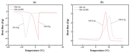
Figure 2.
(a) DSC curve of CPCM solidification process; (b) DSC curve of CPCM melting process.

Table 1.
Material parameter settings.
The finite volume discretization approach was employed to numerically solve the governing equations of the thermal energy storage module, while an iterative linear algebraic solver addressed the latent heat transition dynamics. For the cooling discharge phase, the initial temperature of the phase-change unit was set to T0 = 2 °C, with an entry temperature of 12 °C, and a flow velocity of 0.05 m·s−1; The initial temperature of the phase-change unit in the cold storage process is T0 = 12 °C, the inlet temperature is 2 °C, and the inlet velocity is 0.05 m·s−1. The boundary condition for the outflow is configured as a pressure outlet.
2.1.4. Grid Independence Verification and Model Verification
In order to verify the independence of the grid, it is necessary to select as few grid numbers as possible under the premise of ensuring the calculation accuracy, so as to improve the calculation speed. In this study, the grid independence of the model with an HTF channel of 10 mm and a PCM cell size of 500 × 250 × 30 mm3 is verified. When the grid number is 14,000, 24,012, 38,316, 55,000 and 86,250, the cold release process of the phase-change energy storage unit is numerically simulated, and the change curve of the PCM liquid-phase ratio at 4000 s is obtained, as illustrated in Figure 3a. When the number of grids is 55,000 and 86,250, the liquid-phase ratio is nearly identical. Hence, to save computational resources, it is feasible to select 55,000 grids for the computation.
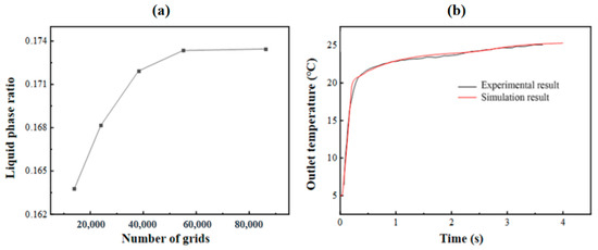
Figure 3.
(a) Step independence verification; (b) comparison and verification of experimental and simulated outlet temperatures.
To verify the effectiveness of the calculation model, the experimental values from reference [14] of the flat-panel phase-change energy storage unit were simulated. In this study, the model of 0.5 m × 0.25 m × 0.0035 m commercial phase-change plate made of 2 mm thick HDPE and a phase-change storage tank with a thickness of 10 mm HTF channel were simulated, and the experimental results were compared. Figure 3b shows the variation in the energy storage process simulation and experimental outlet temperature over time when the inlet flow is 240 kg·h−1 and the HTF inlet temperature is about 25 °C. It is evident that the simulation outcomes show a high degree of consistency with the experimental results, and the average relative error remains below 5%.
2.1.5. Evaluation Index
In the course of applying the phase-change storage air-conditioning system, when it comes to the performance requirements of the thermal energy storage device relying on phase change, the main aspects taken into account are the storage and release rate, the energy storage density of the device, the operating efficiency of the device, and the variation of the outlet temperature during the cold release process. To explore how different structures affect the performance of flat-panel phase-change energy storage units in the practical application of phase-change storage air-conditioning systems, the phase-change release and storage rate, as well as the operation efficiency of the flat-panel phase-change energy storage units, were defined. The specific calculation methods are as follows:
where Q is the stored/released energy of the flat-panel phase-change energy storage unit, including latent heat and sensible heat, kJ; is the mass of the phase-change material, kg; and and are the isobaric specific heat capacity in the solidification and melting states of the PCM, respectively, kJ·kg−1·K−1.
where θ is the unit phase-change storage/release rate of the flat-panel phase-change energy storage unit; V is the volume of the flat-panel phase-change energy storage unit, including the volume of PCM and HTF, m3; and t is the completion time of the phase change of the flat-panel phase-change energy storage unit, s.
where φ is the operating efficiency of the flat-panel phase-change energy storage unit, and the calculation method is the ratio of heat transfer power and operating power during the storage/release process. The larger the φ value, the higher the operating efficiency of the flat-panel phase-change energy storage device; is the storage/release power of the phase-change energy storage unit, W; is the work done by the phase-change energy storage unit to overcome the resistance per unit time, referred to as the resistance power, W; is the operating pressure drop per unit volume HTF of the flat-panel phase-change element, Pa; and is the unit volume flow rate of HTF, m3·s−1.
The heat transfer power and the unit phase-change storage/release rate mainly mirror the heat transfer speed of the phase-change energy storage device. Meanwhile, the operating efficiency of the device indicates the alterations in heat transfer and the occurrence of energy loss during the device’s operation. During the cold storage and release processes, there exists energy loss in the heat transfer mode of the device. It is not possible to completely store or release all the energy. Therefore, in order to describe and quantify how energy is utilized during the operation of the device, the energy utilization efficiency η is defined:
where η is the energy utilization efficiency of the phase-change energy storage device; m is the mass flow rate of HTF, kg·s−1; and ∆T represents the temperature disparity between the inlet and outlet of the HTF, °C.
2.2. Phase-Change Cold Storage Experiment
2.2.1. Experimental Bench System Principle
To investigate the impact of various operating conditions on the energy storage performance of the flat-panel phase-change-based thermal energy storage device, a high-performance experimental system for researching the performance of the flat-panel phase-change-based thermal energy storage device was designed and constructed.
HDPE (high-density polyethylene) has excellent chemical inertness to organic phase-change materials (fatty acids, paraffins). Metallic materials can react corrosively with the acidic components of PCM (lauric acid), resulting in structural damage or thermal performance degradation. HDPE’s low permeability effectively prevents the leakage of liquid PCM. Metal containers are susceptible to micro-cracking due to weld fatigue during thermal expansion/contraction, whereas the flexibility of HDPE is self-adapting to volume changes.
A schematic illustration is presented in Figure 4a, while the physical photograph is depicted in Figure 4b. The experimental system is primarily composed of the flat-panel phase-change-based thermal energy storage device, the cold/hot water circulation system, and the data acquisition system. Among them, the cold/hot water circulation system is composed of a low-temperature constant-temperature reaction bath (including a heat pump unit, water tank, water pump, and temperature control system) and a DN25 pipeline and insulation structure. The data acquisition system consists of a temperature sensor, flow sensor, type K thermocouple, Agilent data acquisition instrument and computer. During the experiment, the cold and hot water flow through the flat-panel thermal energy storage device based on phase change, and the phase-change storage unit carries on the flow heat exchange.
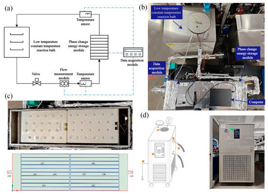
Figure 4.
Experimental research system of storage/release operation performance of a flat-panel thermal energy storage device based on phase change: (a) system schematic diagram; (b) physical drawings of the experimental system; (c) interior view and distribution of temperature measurement points of flat-panel thermal energy storage device based on phase change; (d) low-temperature and constant-temperature reaction bath model and physical drawings.
2.2.2. Main Equipment of Experimental Bench System
- (1)
- Flat-panel thermal energy storage device based on phase change
The flat-panel thermal energy storage device based on phase change is composed of a box, a cover plate and a flat-panel phase-change storage unit. The box and cover plate are made of stainless steel and have a certain bearing capacity to ensure the smooth progress of the experiment. There are 20 phase-change cold storage units with length, width and height of 450 mm × 300 mm × 30 mm, which are horizontally stacked inside the box body. The spacers are adjusted to ensure that the gap between the flat-panel units, the flat-panel units and the bottom of the box, and the flat-panel units and the cover plate are all 4 mm. To ensure uniform fluid distribution, 100 mm transition zones were incorporated at both the inlet and outlet of the enclosure, complemented by flow-straightening grids. The phase-change-based flat-plate thermal storage module, depicted in Figure 4c, features a stacked arrangement of organic PCM-filled units, achieving a volumetric packing density of approximately 79%.
To acquire the heat transfer features within the flat-panel phase-change-based thermal energy storage device during the storage and release processes, 8 typical temperature measuring points inside the device were chosen, as presented in Figure 4c. Points 101 and 102 keep track of the phase-change heat at the bottom of the device. Points 103, 104, 105, and 106 monitor the phase-change heat in the middle part of the device. Meanwhile, points 107 and 108 are used to monitor the heat transfer between the phase-change plates at the top of the device. Moreover, to study the overall heat exchange and energy storage of the device, two temperature monitoring points, 109 (inlet) and 110 (outlet), are also arranged at the inlet and outlet of the device.
- (2)
- Low-temperature constant-temperature reaction tank
In this experimental setup, a low-temperature constant-temperature reaction bath equipped with a 200 L water tank was utilized to supply cold water storage and hot water release for the experimental system. The heat pump within the low-temperature constant-temperature reaction bath carried out heat exchange with the water in the water tank. A constant temperature controller featuring a temperature control accuracy of ±0.5 °C was employed to guarantee the stability of the water temperature at the inlet of the phase-change cold storage device. Additionally, the water system in the phase-change storage system was regulated by making use of the built-in pump and the ball valve at the return water position in the low-temperature and constant-temperature reaction bath, so as to ensure the normal and stable operation of the experimental system. The low-temperature constant-temperature reaction bath is shown in Figure 4d.
- (3)
- Agilent 34970A Data Acquisition Instrument
The Agilent 34970A Data Acquisition Instrument is effective in providing accurate temperature data acquisition for temperature measurements using type T thermocouples, which are typically made of copper and copper alloys and are widely used for low-temperature measurements, typically in the range of −200 °C to 350 °C, with an accuracy of ±0.5 °C. Sample intervals of 1 s are used for continuous monitoring, and the acquisition time is set to a few hours or a few days to capture trends in the thermocouple’s temperature. We used a time of four hours to capture trends in thermocouple temperature changes.
2.2.3. Experimental Content
- (1)
- Cold storage experiment
The water tank in the low-temperature thermostatic bath was set to 12 °C, and the circulation pump, along with the connecting valves between the bath and the piping system, was activated. This allowed the 12 °C water to undergo thorough thermal exchange with the phase-change-based flat-plate thermal storage module. Temperature variations at various sensor points within the module, as well as at the inlet and outlet, were continuously monitored. Once all temperature readings stabilized, the initialization phase for the cold storage experiment was deemed complete.
Subsequently, the system pump and the connecting valves between the thermostatic bath and the piping system were shut off. The water tank temperature was then adjusted to 2 °C. After the tank temperature stabilized at 2 °C, the experimental system’s circulation pump and connecting valves were reopened, enabling cold water to flow through the phase-change thermal storage module and flat-plate units for heat exchange and cold storage. Simultaneously, the data acquisition system was activated. The cold storage experiment concluded when all temperature monitoring points reached a stable state. Throughout the experiment, fluid inlet temperatures and flow rates were varied to study performance under different operational conditions. The experimental working conditions were set as shown in Table 2.
Table 2.
Cold storage experiment condition setting.
- (2)
- Cold release experiment
The water tank in the low-temperature thermostatic bath was adjusted to 2 °C, and the circulation pump, along with the connecting valves between the bath and the piping system, was activated. This allowed the 2 °C circulating water to undergo thorough thermal exchange with the phase-change-based flat-plate thermal storage module. Temperature variations at various sensor points within the module, as well as at the inlet and outlet, were continuously monitored. Once all temperature readings stabilized, the initialization phase for the cold release experiment was completed.
Next, the system pump and the connecting valves between the thermostatic bath and the piping system were shut off. The water temperature in the bath was then set to 12 °C. After the tank temperature stabilized at 12 °C, the system pump and connecting valves were reopened, enabling water to flow through the phase-change thermal storage module and flat-plate units for heat exchange and cold release. Simultaneously, the data acquisition system was activated. The cold release experiment concluded when all temperature monitoring points reached a stable state. Throughout the experiment, fluid inlet temperatures and flow rates were adjusted to study performance under varying operational conditions. The experimental working conditions were set as shown in Table 3 below.
Table 3.
Cold release experiment condition setting.
3. Results and Discussions
3.1. Influence of Cell Structure on the Overall Performance of Cold Storage
Figure 5 shows the completion time of the phase change in the PCM of the flat-plate phase-change cold storage unit with different structural dimensions under the cooling condition of inlet temperature of 2 °C and flow rate of 0.05 m/s. The results show that the completion time of the phase-change cold storage unit increases with the increase in the thickness of HPCM when the flow channel gap HHTF is kept constant. The results show that, when the flow channel gap HHTF is kept constant, the completion time of the phase-change cold storage increases with the increase in the thickness of HPCM, and the increase gradually increases. On the other hand, when the HPCM is kept constant, the phase-change completion time decreases and then increases with the increase in the runner gap HHTF.
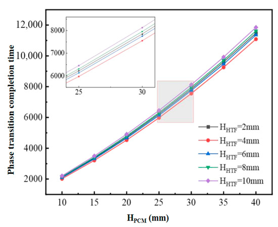
Figure 5.
Completion time of PCM phase change for different sizes of flat-plate phase-change storage units.
Figure 6 shows the changes in heat transfer power during the cooling process of phase-change units with different structural dimensions. When the flow channel gap HHTF is kept constant, although increasing HPCM increases the cooling capacity, the increase in the completion time of the phase-change cooling is larger, which results in the decreasing in the final phase-change heat transfer power, but the decreasing amplitude of the decrease is gradually reduced. Therefore, when the HHTF is constant, a larger HPCM can be chosen in order to ensure a higher density of cold storage; on the other hand, when the HPCM remains constant, the heat transfer power of the flat-plate phase-change thermal energy storage unit increases and then decreases with the increase in the HHTF. Figure 7 shows the variation in the unit cooling rate of the phase-change units with different structural dimensions, reflecting the average cooling rate per unit volume of flat-plate phase-change units with different phase-change energy storage densities formed under different combinations of HPCM and HHTF. The figure shows that the unit cooling rate of the phase-change cooling storage unit decreases with the increase in HHTF and decreases with the increase in HPCM. This is mainly because, when HPCM is kept constant, the cold storage capacity of the phase-change refrigeration unit remains unchanged, but the increase in HHTF leads to the change in the unit volume cold storage density, which is larger than the fluctuation of the change in the phase-change completion time. Meanwhile, when HHTF is kept constant, the cold storage density of the phase-change refrigeration unit is increased with the increase in HPCM, but the increase is smaller than that of the increase in the phase-change completion time. In addition, with the increase in HPCM, the decrease in the unit cooling rate of the unit gradually decreases, and the difference in the unit cooling rate caused by the change in HHTF decreases.
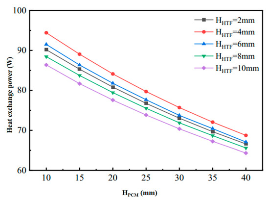
Figure 6.
Variation of heat transfer power of phase-change units with different structural dimensions in cold storage process.
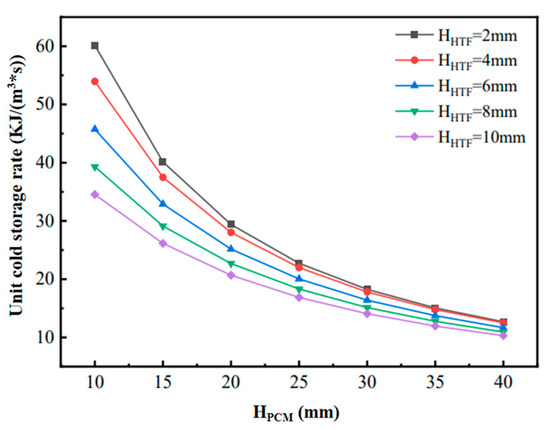
Figure 7.
Variation of unit cold storage rate for phase-change units with different structural dimensions.
The effect of the PCM layer thickness on heat transfer efficiency is an important design factor in phase-change thermal energy storage devices. A thicker PCM layer increases the thermal resistance during the heat transfer process, which slows down the storage and release of heat. However, a PCM layer that is too thin may result in heat not being stored efficiently during the phase-change process, reducing the overall energy density of the system. Therefore, the thickness of the PCM layer needs to find an optimal balance between heat transfer efficiency and thermal storage capacity. We propose optimizing the heat transfer process by adjusting the PCM layer thickness in conjunction with the appropriate heat transfer fluid flow rate and temperature. It has been shown that increasing the thickness of the PCM layer increases the resistance to heat transfer, but the proper thickness can help balance the heat transfer rate with the energy storage capacity, thus enhancing the phase-change efficiency.
3.2. Thermal Performance Analysis of the Flat-Panel Phase-Change Energy Storage Unit
The thermal performance of the flat-plate phase-change energy storage module with HHTF = 4 mm and HPCM = 30 mm was simulated and analyzed. Figure 8a,b illustrates the temporal evolution of the PCM liquid fraction during thermal cycling. During the cooling storage phase, the liquid fraction progressively declines, approaching zero, with a phase transition duration of 8331 s. In contrast, the cooling discharge phase exhibits a significantly shorter transition time of 3883 s, attributed to the enhanced thermal driving force from the higher inlet–PCM temperature gradient. As shown in Figure 8c,d, the thermal exchange intensity between the HTF and PCM diminishes continuously throughout both the solidification and melting processes.
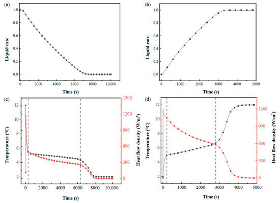
Figure 8.
Thermal behavior evolution in a flat-panel phase-change energy storage unit: (a) liquid-phase fraction of PCM the cooling storage process; (b) liquid-phase fraction of PCM during cold release process; (c) PCM temperature and heat flow density during cold storage process; (d) PCM temperature and heat flow density during cold release process.
Figure 9 reveals that the PCM at the HTF–PCM interface initiates solidification at 2500 s. Over time, the freezing front propagates progressively toward the module’s core, forming an inclined solid–liquid boundary. Notably, the solidifying process decelerates along the HTF flow direction, while centrally positioned units exhibit accelerated phase transition kinetics. Furthermore, symmetrical patterns emerge in both liquid fraction gradients and thermal profiles across the PCM-based system. This may be due to the overall distribution of the fluid in the flow channel between the phase-change cold storage plate units being relatively uniform. The cold release process shows the same variation characteristics as the cold storage process.
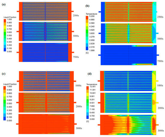
Figure 9.
Variation in the liquid-phase fraction and temperature in flat-panel phase-change energy storage unit: (a) liquid-phase ratio distribution during cold storage process; (b) temperature distribution during cold storage process; (c) liquid-phase ratio distribution during cold release process; (d) temperature distribution during cold release process.
To analyze fluid dynamics and thermal gradients, three horizontal sampling planes were established at Y = 0.34 m (upper), Y = 0.204 m (central), and Y = 0.068 m (lower), as depicted in Figure 10. Positioned at the inlet/outlet elevation, the central plane exhibited peak fluid velocities during thermal cycling phases, while identical flow rates were observed in the upper and lower planes. Temperature profiles along the X-axis displayed progressive elevation across all levels, stemming from prolonged HTF-PCM thermal interactions that decelerated phase transitions near the outlet. Furthermore, the central plane demonstrated a slower temperature ascent compared to peripheral regions. This highlights a critical trade-off: while increased flow rates enhance instantaneous heat transfer rates, they concurrently reduce total thermal exchange capacity due to abbreviated HTF residence times.
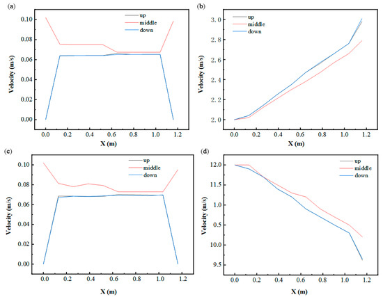
Figure 10.
Variation in fluid velocity and temperature in the X-axis direction: (a) fluid velocity at 2500 s (in cold storage process); (b) fluid temperature at 2500 s (in cold storage process); (c) fluid velocity at 1000 s (in cold release process); (d) fluid temperature at 1000 s (in cold release process).
3.3. Impact of Inlet and Outlet Locations
To evaluate the impact of inlet/outlet configurations on thermal-fluid dynamics and energy retention efficacy, multiple structural variants were engineered, as detailed in Table 4.
Table 4.
Design of different inlet and outlet positions.
As illustrated in Figure 11a,c, the U–U configuration exhibits a prolonged phase transition duration compared to the other five structural variants, while the remaining designs demonstrate nearly identical liquid fraction evolution patterns. This discrepancy likely stems from the significant impact of varying inlet/outlet configurations on fluid dynamics within transitional zones near the ports, though flow channel velocity distributions exhibit minimal variation. Figure 11b further indicates comparable thermal transfer rates across all configurations, attributable to their similar volumetric energy storage capacities and equivalent cooling storage completion times. Notably, Figure 11d reveals analogous trends between thermal power and discharge efficiency to those observed during cooling storage, albeit with markedly elevated heat transfer intensities during the discharge phase.
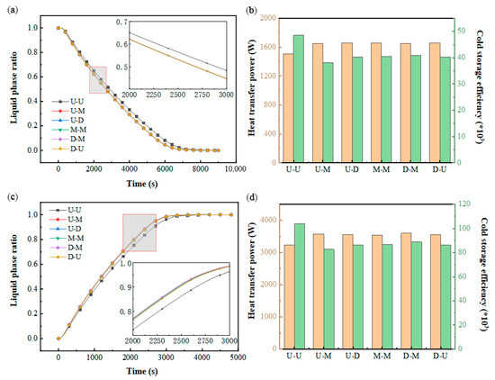
Figure 11.
Impact of the structure of the inlet and outlet: (a) variation in the liquid-phase ratio in PCM during cold storage process; (b) variation in heat transfer power and cold storage efficiency during cold storage process; (c) variation in liquid-phase ratio in PCM during cold release process; (d) variation in heat transfer power and cold release efficiency during cold release process.
Figure 12 illustrates the temporal evolution of the outlet temperature during the cooling discharge cycle. Notably, the U–U configuration exhibits elevated outlet temperatures in the secondary phase transition stage compared to the other five variants. This observation implies that port configurations exert minimal impact on the operational efficacy of multi-layered flat-plate PCM modules featuring constrained flow channels. Meanwhile, the inlet and outlet positions can be adjusted according to the requirements of the project.
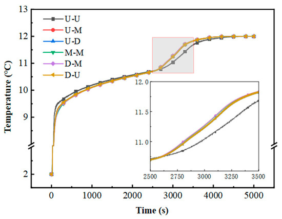
Figure 12.
Variation in outlet temperature with time.
3.4. Impact of Constant Inlet Power
We define the inlet power P0,in in terms of the inlet velocity 0.1 m/s, inlet temperature T0,in = 12 °C (cold release)/2 °C (cold storage), and initialization temperature T0 = 2 °C (cold release)/12 °C (cold storage). Four sets of coupling conditions with different inlet temperatures and inlet velocities are obtained, as shown in Table 5.
Table 5.
Inlet temperature and velocity variations at constant inlet power.
As depicted in Figure 13a, the time required for complete PCM solidification escalates with higher inlet flow rates and thermal input conditions. Under fixed inlet power settings, the thermal exchange dynamics of the PCM-based cold storage system exhibit pronounced sensitivity to variations in inlet temperature. Figure 13c shows that the PCM melting completion time increases with an increasing inlet flow rate and decreasing inlet temperature. Compared with the cold storage process, the change in operating conditions under constant power inlet conditions has less effect on the phase-change completion time because of the larger heat transfer temperature difference in the cold release process. Figure 13b,d illustrates the trends in the heat transfer power and energy utilization efficiency of the system. During the cooling storage phase, elevated inlet velocities and temperatures correlate with a reduction in thermal transfer rates. Conversely, in the cooling discharge phase, higher flow rates coupled with lower inlet temperatures similarly diminish heat exchange performance. Under steady inlet power conditions, the energy utilization efficiency remains stable, consistently operating at a high level.
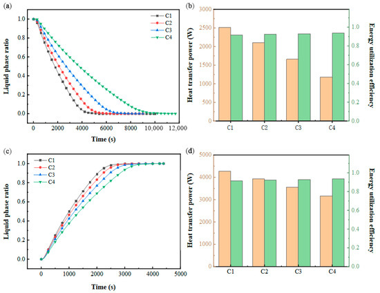
Figure 13.
Performance at constant inlet power: (a) variation in the liquid-phase ratio with time during cold storage process; (b) variation in heat transfer power and energy utilization efficiency during cold storage process; (c) variation in liquid-phase ratio with time during cold release process; (d) variation in heat transfer power and energy utilization efficiency during cold release process.
Comparing the variation in the energy efficiency ratio under different installed capacities and operating conditions, it can be seen that the energy efficiency ratio of the energy storage unit increases with the inlet temperature. Under conditions of higher device efficiency, the pressure-related energy losses of the cold storage system are minimized. Elevating the inlet temperature enhances the operational efficacy of the refrigeration module. Deploying high-performance refrigeration units in conjunction with elevated inlet temperature parameters significantly boosts the overall energy efficiency of the system. Additionally, Figure 14b highlights the profound influence of inlet temperature on both thermal transfer capabilities and energy retention dynamics within the flat-plate PCM-based module during the cooling discharge phase.
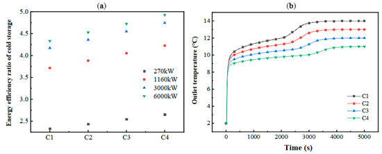
Figure 14.
Variation in (a) energy efficiency ratio and (b) outlet temperature in the energy storage unit.
3.5. Impact of Unit Stacking Form
The compositional structure of the device is investigated under the same energy storage density. The horizontal and vertical stacking structure is shown in Table 6.
Table 6.
Horizontal and vertical stacking of different phase-change energy storage units.
The comparative analysis revealed that vertically aligned two-column configurations exhibited longer phase transition durations during cooling storage and discharge cycles compared to three-column arrangements under identical vertical stacking conditions. Conversely, variations in vertical alignment significantly amplified temporal disparities in phase-change completion when horizontal column quantities remained constant. Figure 15b,d illustrates the thermal evolution of PCM during these cycles, demonstrating a direct correlation between temperature gradients and liquid fraction dynamics. During cooling storage, configurations A3/A6 displayed abbreviated steady-state solidification plateaus relative to A1/A4, yet they were aligned closely with A2/A5. Notably, the A2/A5 configurations with uniform vertical stacking exhibited dual solidification plateaus and the shortest phase transition durations. In the discharge phase, A3/A5 demonstrated compressed thermal plateaus, while A2/A6 featured dual stable melting plateaus, mirroring the cooling storage behavior.
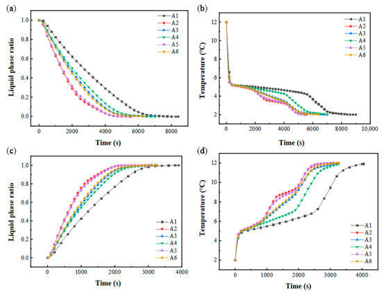
Figure 15.
Performance in different stacking forms: (a) variation in liquid-phase ratio with time during cold storage process; (b) variation in PCM average temperature with time during cold storage process; (c) variation in liquid-phase ratio with time during cold release process; (d) variation in PCM average temperature with time during cold release process.
In cold storage air-conditioning systems, the duration of energy retention plays a pivotal role in overall efficiency. The structural configuration of stacked units significantly impacts operational efficacy, as their arrangement has a profound effect on heat transfer dynamics. As shown in Figure 16, thermal transfer capacities vary markedly across different configurations, aligning closely with observed phase transition durations. The analysis of system efficiency revealed values exceeding 104, indicating that resistive energy losses remain significantly lower than thermal exchange capacities. This underscores the advantage of optimizing unit stacking to minimize energy dissipation while maximizing performance. At the same time, combined with the trend of the heat exchange power and cold storage efficiency, the operating resistance of the A1 structure was shown to be the smallest, and the operating resistance of the A5 was the largest. In the process of cold release, the cold release efficiency of different structures is larger than 30 × 103. Therefore, although different plate stacking forms cause different pressure losses in the flat-panel phase-change energy storage unit, it is a smaller value compared with the heat transfer power. Within a certain amount of stacking, the stacking form can be ignored.
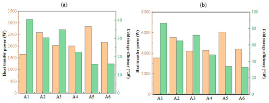
Figure 16.
Variation in heat transfer power and cold storage/release efficiency under different stacking forms: (a) during cold storage process; (b) during cold release process.
3.6. Experimental Study of Flat-Panel Phase-Change Energy Storage Device
3.6.1. Analysis of Heat Transfer Performance
As illustrated in Figure 17a, the temporal temperature profiles of the PCM-based thermal storage module’s inlet, outlet, and internal monitoring points are presented under operational conditions of a 2 °C entry temperature and a 1200 L·h−1 flow velocity. During the initial 500 s of cooling storage, no phase transition occurred, with the PCM unit at approximately 12 °C engaging in convective heat exchange with the 2 °C coolant, and the temperature of PCM decreased rapidly, which also led to a rapid temperature drop at the monitoring point. In the stable stage of cold storage (500~7000 s), the phase-change unit began to solidify gradually, and the temperature of PCM was basically constant, resulting in a slow decrease in temperature at each measuring point. At the end of the cold storage stage (7000~8000 s), the phase change was basically completed, and the temperature of the monitoring point dropped rapidly; finally, it was basically the same as the inlet temperature. In addition, the farther the monitoring point was from the inlet position of the device at the same altitude, the greater the temperature difference with the inlet fluid. At the same time, the temperature of the detection point at each height was different, and the temperature at the middle height was the lowest, followed by the bottom height and the top height. This means that the PCM at the middle height has the best heat transfer with the inlet fluid, possibly due to the uneven distribution of water velocity among the phase-change units in the device.
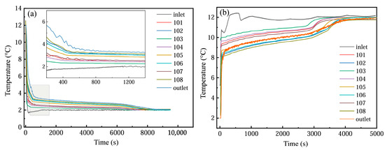
Figure 17.
Temperature changes at different monitoring points: (a) cold storage process; (b) cold release process.
As depicted in Figure 17b, the temporal variations in the inlet/outlet temperatures and internal monitoring point temperatures within the PCM-based thermal storage module are analyzed under operational parameters of 12 °C entry temperature and 1200 L·h−1 flow velocity. The cooling discharge phase exhibits temperature evolution patterns analogous to those observed during the cooling storage cycle. However, due to the enhanced thermal driving force from the elevated temperature gradient, the phase transition duration was markedly reduced compared to the storage process. In addition, in the actual cycle, the inlet temperature is not constant, but there is a fluctuation range of about 1 °C.
3.6.2. Influence of Inlet Flow on the Performance of Energy Storage
Figure 18 illustrates the temporal temperature variations at the inlet and outlet of the PCM-based thermal storage module during both cooling storage and discharge cycles under three flow conditions (800, 1000, and 1200 L·h−1). Elevated flow velocities correlate with a progressive reduction in inlet–outlet temperature differentials during phase transitions, accompanied by a corresponding decline in phase transition completion times.
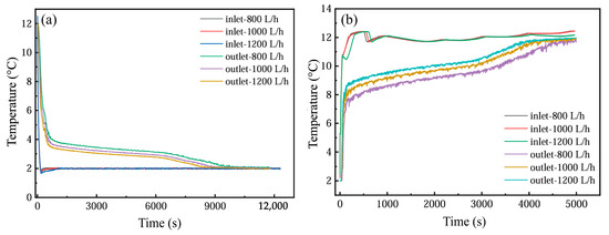
Figure 18.
Temperature changes at the outlet under different flow rates: (a) cold storage process; (b) cold release process.
Figure 19 delineates the impact of inlet flow rates on the energy retention performance of the PCM-based thermal storage system. The increased inlet flow rate significantly enhances heat transfer, especially during phase-change processes. At higher flow rates, the heat exchange between the heat transfer fluid (HTF) and the phase-change material (PCM) becomes more efficient. This is due to the increased convective heat transfer coefficient of the fluid at higher flow rates, which allows for faster heat transfer from the fluid to the PCM, contributing to a faster rate of phase change in the PCM. Specifically, higher inlet flow rates enhance the heat exchange effect between the PCM and the HTF by reducing the thickness of the thermal boundary layer, thereby shortening the melting/freezing time.
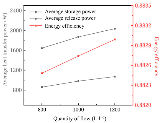
Figure 19.
Influence of inlet flow on energy storage performance.
However, flow rates that are too high may also have some negative effects. Excessively fast flow rates during the cooling process may lead to the inhomogeneity of the heat transfer, especially near the solid–liquid interface of the PCM, which may result in unstable heat exchange. Nevertheless, in the vast majority of application scenarios, the increase in the flow rate usually accelerates the phase-change process, especially during the cooling phase, where the melting rate of the PCM increases significantly, which contributes to the overall heat exchange capacity of the system.
As the inlet flow rate increases, the thermal power gain of the system significantly exceeds that of the heat release phase relative to the heat storage phase, due to the higher flow rate promoting more rapid melting and phase-change processes of the PCM. At the same time, energy utilization increases with higher flow rates, but this increase tends to be small in practice, indicating that changes in flow rate have limited energy efficiency gains under general operating conditions.
3.6.3. Influence of Inlet Temperature on Device Energy Storage Capacity
Figure 20a depicts the thermal variations at the inlet and outlet of the PCM-based system under varying inlet temperatures during the cooling storage cycle. As the inlet temperature rises, the phase transition duration becomes progressively prolonged, with a pronounced extension observed at 4 °C—a condition unfavorable for overnight cooling storage. Concurrently, higher inlet temperatures correlate with a diminishing inlet–outlet thermal gradient, signaling a decline in heat transfer capacity. Figure 20b examines the impact of inlet temperatures on outlet dynamics during the cooling discharge phase. The analysis reveals that phase transition completion times decline as inlet temperatures increase. Owing to the significant thermal gradient between the discharge inlet and PCM phase-change thresholds, the inlet temperature exerts minimal influence on outlet thermal profiles.
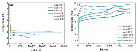
Figure 20.
(a) Inlet temperature change during cold storage; (b) inlet temperature change during cold release.
Figure 21 shows the influence of different inlet temperatures on the energy storage performance of the device. Changes in inlet temperature have a significant effect on heat transfer efficiency and phase-change processes. In the cooling energy storage process, the change in the heat transfer drive with increasing inlet temperature leads to a reduction in the thermal storage power of the system. This is because, at higher inlet temperatures, the temperature difference (thermal gradient) between the PCM and the heat transfer fluid (HTF) decreases, slowing down the phase-change process, especially during the cooled storage phase. In this case, the return of the phase-change material (PCM) from the liquid phase to the solid phase becomes slower, thus affecting the effective storage of energy.
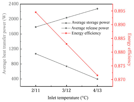
Figure 21.
Influence of inlet temperature on device energy storage performance.
On the other hand, during the cooling release process, the higher inlet temperature induces the PCM to release heat more quickly due to the larger temperature gradient, which enhances the exothermic power. As a result, the cold release power increases with the increase in the inlet temperature, and the variation in the cold storage process is larger. This suggests that the temperature gradient has a more significant effect on the heat transfer efficiency during the cool storage stage, while the cold release stage can better withstand higher inlet temperatures.
We also found that energy utilization efficiency decreased by approximately 2.5% when the inlet temperature increased from 11–13 °C. This highlights the trade-off between heat input and system efficiency, suggesting that, while exothermic efficiency increases when increasing the inlet temperature, storage efficiency suffers. Therefore, rational control of the inlet temperature range is a key factor in optimizing system heat transfer and energy efficiency.
3.7. Comparison Between Experimental Results and Numerical Simulation
Based on the numerical model, numerical simulations, and predictions of the physical model of the flat-panel thermal energy storage device based on the phase change carried out, Figure 22 shows a comparison with the experimental results. In the process of cold storage, the numerical prediction results show that the change trend for outlet temperature is basically consistent with the experimental results, but the predicted outlet temperature is first higher than the experimental value and then gradually decreases to the experimental value, and it is finally lower than the experimental value. The phase transition duration observed in the experiments was shorter than the simulated completion time. During cooling discharge, numerical predictions of outlet temperature trends aligned closely with storage phase behavior but indicated earlier phase transitions compared to the empirical results. This discrepancy may stem from the assumption of uniform thermal conductivity in simulations, whereas the experimental setups exhibited localized material inhomogeneities that impeded PCM thermal transfer efficacy, thereby reducing experimental heat transfer rates relative to computational models.
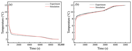
Figure 22.
(a) Comparison of outlet temperature in cold storage process; (b) comparison of outlet temperature in cold release process.
Long-term operating pressure exists during the phase transition of PCM, which is usually accompanied by a volume expansion of 5–15% during the solid–liquid phase transition; this is particularly significant for paraffin-based materials. If the vessel is completely closed and there is no expansion space, the internal pressure can rise to 0.1–0.3 MPa. The HDPE plate energy storage unit examined in this study avoids the pressure accumulation due to its flexible structural design and reserved expansion gap. The elastic modulus of the HDPE allows moderate deformation and absorbs the volumetric expansion stresses; a 4 mm fluid channel (HTF gap) is set up between the neighboring PCM plates, which provides the buffer space for the expansion of the phase change.
Overall, discrepancies between simulated and empirical outcomes remain minimal, with analogous trend consistency, providing robust theoretical and numerical foundations for optimizing the design and energy retention performance of flat-plate PCM-based thermal storage systems.
4. Conclusions
This study presents the design of a flat-panel thermal energy storage device relying on phase change. We examine the influences of the inlet and outlet location, operating parameters, and horizontal and vertical stacking structure of the flat-panel thermal energy storage device based on phase change on the comprehensive performance of the device, in order to provide an optimization reference for the structural design and operation of the device, and the operation characteristics of the device are analyzed.
- (1)
- The fluid distribution among the units in the device is uniform, and the inlet and outlet locations have little influence on the comprehensive performance.
- (2)
- The inlet temperature plays a crucial role and has a substantial influence on the overall performance of the device under constant inlet power operating conditions, so the operating temperature can be adjusted preferentially to respond to the system performance quickly.
- (3)
- The lateral stacking of phase-change units can increase the heat transfer rate of the device, and the use of units with high unit energy storage efficiency to replace units with poor efficiency can effectively enhance the overall rate of heat transfer.
- (4)
- An experimental setup for the flat-plate PCM-based thermal storage system was successfully constructed. The empirical findings indicate that elevated flow velocities enhance phase transition kinetics within the module but exert negligible effects on energy retention efficacy. While inlet temperatures significantly influence thermal storage and exchange dynamics, their impact on the cooling discharge process remains constrained.
Although this study provides detailed modelling and experimental validation of the phase-change energy storage system, there are still some limitations:
- (1)
- Differences between experimental and simulation conditions: The simulations in this study are based on the assumed conditions of uniform flow and a steady state, which are not fully valid in practice; this may lead to a discrepancy between simulation results and actual results.
- (2)
- Gap between model simplification and practical application: The complex physical processes of the phase-change energy storage system model in this study are simplified, such as the non-linear behavior of the phase-change material and the dynamics of the system’s thermodynamic processes.
- (3)
- Influence of environmental factors: A constant ambient temperature and fluid flow rate are assumed in this study. However, in real applications, the environmental and operating conditions may change, and these factors may affect the actual performance of the phase-change energy storage system.
In order to further enhance the accuracy and practical application value of this study, we present some future research directions and suggested application improvements:
- (1)
- Consideration of dynamic operating conditions: This study assumed fixed operating conditions; however, in practical applications, the operating conditions of the system (e.g., flow rate, ambient temperature, etc.) will change. Future research should consider more dynamic operating conditions to simulate the effects of different loads and environmental changes on the performance of phase-change energy storage systems.
- (2)
- Multi-physics coupled modelling: The performance of phase-change energy storage systems is not only affected by heat transfer but also involves multiple physical processes such as fluid dynamics and the phase-change properties of matter. Future research can further develop multi-physics coupled modelling to improve the accuracy of the model by considering the interactions between different physical fields.
- (3)
- Integration with real air-conditioning systems: The ultimate goal of phase-change energy storage technology is to integrate it with real devices such as air-conditioning systems. Future research should focus on methods of integrating phase-change energy storage systems with existing air-conditioning systems to optimize the matching of the energy storage and release processes to improve the overall energy efficiency of the air-conditioning system.
- (4)
- Environmental impact and life cycle analysis: In future work, research should assess the carbon footprint, energy efficiency, and economics of different phase-change energy storage systems in real-world applications in order to inform sustainable design.
Author Contributions
M.N.: conceptualization, data curation, formal analysis, and investigation. X.Y.: writing—original draft, investigation, and data curation. L.W.: methodology, validation, visualization, and experiments. M.L.: funding acquisition, project administration, resources, and supervision. Z.C.: funding acquisition, project administration, resources, and supervision. All authors have read and agreed to the published version of the manuscript.
Funding
This research received no external funding.
Data Availability Statement
The original contributions presented in this study are included in the article. Further inquiries can be directed to the corresponding author.
Acknowledgments
This work was supported by the Science and Technology Project of China Power Engineering Consulting Group Co., Ltd. “Low and medium temperature efficient phase-change heat storage technology and thermal management research” (DG2-A02-2022).
Conflicts of Interest
Author Minglong Ni, Xiaolong Yue, Mingtao Liu was employed by the company Jiangsu Power Design Institute Co., Ltd. The authors declare that this study received funding from Science and Technology Project of China Power Engineering Consulting Group Co., Ltd. The funder was not involved in the study design, collection, analysis, interpretation of data, the writing of this article or the decision to submit it for publication.
Nomenclature
| English alphabet | |||
| A | inlet cross-sectional area (m3) | t | time (s) |
| Amush | the continuous number of partially solidified regions in a phase transition | T | temperature (K) |
| cp | isobaric heat capacity (J·kg−1·K−1) | T1 | melting point (K) |
| g | gravitational acceleration (m·s−2) | Tin | inlet temperature (K) |
| H | heat content (kJ·kg−1) | Tref | reference temperature (K) |
| ΔH | phase-change latent heat (kJ·kg−1) | ΔT | HTF inlet and outlet temperature difference (K) |
| mpcm | mass of phase-change material (kg) | v | fluid velocity (m·s−1) |
| p | pressure (Pa) | V | capacity (m3) |
| Pτ | running resistance power (W) | Vin | inlet velocity (m·s−1) |
| Pin | constant inlet power (W) | W | heat transfer power (W) |
| Q | total storage energy (kJ) | ||
| Greek alphabet | |||
| β | liquid-phase ratio | θ | unit phase transition rate (kJ·m−3·s−1) |
| ε | A number less than 0.0001 | µ | dynamic viscosity (Pa·s) |
| ζ | energy efficiency ratio of cold storage | ρ | density (kg·m−3) |
| η | energy utilization efficiency | φ | unit operating efficiency |
References
- Gao, Y.; Zhang, X.; Xu, X.; Liu, L.; Zhao, Y.; Zhang, S. Application and research progress of phase change energy storage in new energy utilization. J. Mol. Liq. 2021, 343, 117554. [Google Scholar] [CrossRef]
- Ma, H.; Wang, H.; Yan, Z.; Yu, Q. Evaluating peak-regulation capability for power grid with various energy resources in Chinese urban regions via a pragmatic visualization method. Sustain. Cities Soc. 2022, 80, 103749. [Google Scholar] [CrossRef]
- She, X.; Cong, L.; Nie, B.; Leng, G.; Peng, H.; Chen, Y.; Zhang, X.; Wen, T.; Yang, H.; Luo, Y. Energy-efficient and-economic technologies for air conditioning with vapor compression refrigeration: A comprehensive review. Appl. Energy 2018, 232, 157–186. [Google Scholar] [CrossRef]
- Hirmiz, R.; Teamah, H.; Lightstone, M.; Cotton, J. Performance of heat pump integrated phase change material thermal storage for electric load shifting in building demand side management. Energy Build. 2019, 190, 103–118. [Google Scholar] [CrossRef]
- Sharma, A.; Tyagi, V.V.; Chen, C.R.; Buddhi, D. Review on thermal energy storage with phase change materials and applications. Renew. Sustain. Energy Rev. 2009, 13, 318–345. [Google Scholar] [CrossRef]
- Xie, J.; Wang, W.; Liu, J.; Pan, S. Thermal performance analysis of PCM wallboards for building application based on numerical simulation. Sol. Energy 2018, 162, 533–540. [Google Scholar] [CrossRef]
- Saffari, M.; De Gracia, A.; Fernández, C.; Cabeza, L.F. Simulation-based optimization of PCM melting temperature to improve the energy performance in buildings. Appl. Energy 2017, 202, 420–434. [Google Scholar] [CrossRef]
- Li, S.-F.; Liu, Z.-H.; Wang, X.-J. A comprehensive review on positive cold energy storage technologies and applications in air conditioning with phase change materials. Appl. Energy 2019, 255, 113667. [Google Scholar] [CrossRef]
- Abdulateef, A.M.; Mat, S.; Abdulateef, J.; Sopian, K.; Al-Abidi, A.A. Geometric and design parameters of fins employed for enhancing thermal energy storage systems: A review. Renew. Sustain. Energy Rev. 2018, 82, 1620–1635. [Google Scholar] [CrossRef]
- Zivkovic, B.; Fujii, I. An analysis of isothermal phase change of phase change material within rectangular and cylindrical containers. Sol. Energy 2001, 70, 51–61. [Google Scholar] [CrossRef]
- Liu, M.; Saman, W.; Bruno, F. Validation of a mathematical model for encapsulated phase change material flat slabs for cooling applications. Appl. Therm. Eng. 2011, 31, 2340–2347. [Google Scholar] [CrossRef]
- Ding, C.; Niu, Z.; Li, B.; Hong, D.; Zhang, Z.; Yu, M. Analytical modeling and thermal performance analysis of a flat plate latent heat storage unit. Appl. Therm. Eng. 2020, 179, 115722. [Google Scholar] [CrossRef]
- Iten, M.; Liu, S.; Shukla, A. Experimental validation of an air-PCM storage unit comparing the effective heat capacity and enthalpy methods through CFD simulations. Energy 2018, 155, 495–503. [Google Scholar] [CrossRef]
- Halawa, E.; Bruno, F.; Saman, W. Numerical analysis of a PCM thermal storage system with varying wall temperature. Energy Convers. Manag. 2005, 46, 2592–2604. [Google Scholar] [CrossRef]
- Crespo, A.; Zsembinszki, G.; Vérez, D.; Borri, E.; Fernández, C.; Cabeza, L.F.; de Gracia, A. Optimization of design variables of a phase change material storage tank and comparison of a 2D implicit vs. 2D explicit model. Energies 2021, 14, 2605. [Google Scholar] [CrossRef]
- Nie, B.; Du, Z.; Zou, B.; Li, Y.; Ding, Y. Performance enhancement of a phase-change-material based thermal energy storage device for air-conditioning applications. Energy Build. 2020, 214, 109895. [Google Scholar] [CrossRef]
- Younis, O.; Abderrahmane, A.; Hatami, M.; Mourad, A.; Kamel, G. Thermal energy storage using nano phase change materials in corrugated plates heat exchangers with different geometries. J. Energy Storage 2022, 55, 105785. [Google Scholar] [CrossRef]
- Huang, H.; Wang, Z.; Zhang, H.; Dou, B.; Huang, X.; Liang, H.; Goula, M.A. An experimental investigation on thermal stratification characteristics with PCMs in solar water tank. Sol. Energy 2019, 177, 8–21. [Google Scholar] [CrossRef]
- Ye, W.-B.; Zhu, D.-S.; Wang, N. Fluid flow and heat transfer in a latent thermal energy unit with different phase change material (PCM) cavity volume fractions. Appl. Therm. Eng. 2012, 42, 49–57. [Google Scholar] [CrossRef]
- Xie, S.; Wu, W. Effect of aspect ratio on PCM melting behavior in a square cavity. Int. Commun. Heat Mass Transf. 2023, 143, 106708. [Google Scholar] [CrossRef]
- Hari, B.; Suresh, S.; Kottala, R.K.; Praveenkumar, S. Synthesis and characterization of high thermal conductive leak resistant phase change material for solar photovoltaic panel cooling applications. J. Energy Storage 2025, 122, 116656. [Google Scholar] [CrossRef]
- Prabhu, B.; Arunkumar, T.; Subramanian, P.; Alarifi, A.; Mariappan, M. Conch shell derived bio-carbon/Paraffin as novel composite phase change material with enhanced thermal energy storage properties for photovoltaic module cooling systems. Sol. Energy Mater. Sol. Cells 2025, 281, 113306. [Google Scholar]
- Homlakorn, S.; Velmurugan, K.; Suksri, A.; Wongwuttanasatian, T. Comparative study for photovoltaic cooling using metal mesh inserted eutectic phase change material enclosure. Case Stud. Therm. Eng. 2023, 45, 103024. [Google Scholar] [CrossRef]
- Chang, S.; Zhang, L.; Li, X.; Liu, B.; Meng, Y.; Hu, H. Experimental study of novel paraffin-fatty acid eutectic mixtures for thermal management of electronic devices. J. Energy Storage 2024, 84, 110846. [Google Scholar] [CrossRef]
- Jiang, Z.; Rivero, M.E.N.; Liu, X.; She, X.; Xuan, Y.; Ding, Y. A novel composite phase change material for medium temperature thermal energy storage manufactured with a scalable continuous hot-melt extrusion method. Appl. Energy 2021, 303, 117591. [Google Scholar] [CrossRef]
- Weingrill, H.M.; Resch-Faustera, K.; Lucyshynb, T.; Zaunerc, C. High-density polyethylene as phase-change material: Long-term stability and aging. Polym. Test. 2019, 76, 433–442. [Google Scholar] [CrossRef]
- Oliveski, R.D.C.; Becker, F.; Rocha, L.A.O.; Biserni, C.; Eberhardt, G.E.S. Design of fin structures for phase change material (PCM) melting process in rectangular cavities. J. Energy Storage 2021, 35, 102337. [Google Scholar] [CrossRef]
- Bria, A.; Raillani, B.; Chaatouf, D.; Salhi, M.; Amraqui, S.; Mezrhab, A. Effect of PCM thickness on the performance of the finned PV/PCM system. Mater. Today Proc. 2023, 72, 3617–3625. [Google Scholar] [CrossRef]
- Zhang, X.; Ge, Y.; Lang, P. Experimental investigation and CFD modelling analysis of finned-tube PCM heat exchanger for space heating. Appl. Therm. Eng. 2024, 244, 122731. [Google Scholar] [CrossRef]
- Sonker, V.K.; Sharma, P.; Ram, R.; Sarkar, A. A CFD simulation analysis of the effects of PCM and nanoparticles stored in copper cylinders inside a solar still. J. Energy Storage 2025, 108, 115091. [Google Scholar] [CrossRef]
- Li, Y.; Zhang, X.; Munyalo, J.M.; Tian, Z.; Ji, J. Preparation and thermophysical properties of low temperature composite phase change material octanoic-lauric acid/expanded graphite. J. Mol. Liq. 2019, 277, 577–583. [Google Scholar] [CrossRef]


Disclaimer/Publisher’s Note: The statements, opinions and data contained in all publications are solely those of the individual author(s) and contributor(s) and not of MDPI and/or the editor(s). MDPI and/or the editor(s) disclaim responsibility for any injury to people or property resulting from any ideas, methods, instructions or products referred to in the content. |
© 2025 by the authors. Licensee MDPI, Basel, Switzerland. This article is an open access article distributed under the terms and conditions of the Creative Commons Attribution (CC BY) license (https://creativecommons.org/licenses/by/4.0/).