Abstract
Battery electric vehicles (BEVs) play a key role in reducing CO2 emissions and enabling a climate-neutral economy. However, they suffer from reduced range in cold conditions due to electric cabin heating. Electrically heated thermal energy storage (TES) systems can decouple heat generation from demand, thereby preventing a loss of range. For this purpose, a novel concept based on a directly electrically heated ceramic solid media TES is investigated, aiming to achieve high storage density while enabling both high charging and discharging powers. To assess the feasibility of the proposed TES concept in BEVs, a holistic evaluation of central aspects is conducted, including experimental characterization for material selection, experimental investigations on electrical contacting, and simulations of the electrothermal charging and thermal discharging processes under vehicle-relevant conditions. As a result of the material characterization, a promising material—a silicon carbide-based composite—was identified, which meets the electrothermal requirements under typical household charging conditions and allows reliable operation with silver-metallized electrodes. Design studies with this material show gravimetric energy densities—including thermal insulation demand—exceeding 100 Wh/kg, storage utilization of up to 90%, and fast charging within 25 min, while offering 5 kW at flexible temperature levels for cabin heating during thermal discharging. These results show that the basic prerequisites for such storage systems are met, while further development—particularly in terms of material improvements—remains necessary.
1. Introduction
The transition to a climate-neutral economy is essential for mitigating climate change. In the transport sector, battery electric vehicles (BEVs) powered by renewable energy sources offer significant potential for reducing CO2 emissions. Since the waste heat from an internal combustion engine is no longer available, the required heating power—especially for cabin heating—must be provided entirely electrically. Currently, this is mostly achieved using battery-powered PTC (Positive Temperature Coefficient) heating elements. Under cold environmental conditions, the heating demand can reach up to 5 kW, which can lead to a significant reduction in vehicle range—up to 50% in extreme cases [1,2,3]. Therefore, new approaches for providing thermal energy are crucial for the success of electromobility, particularly with regard to range, efficiency and comfort. One promising solution is the use of thermal energy storage (TES) systems, which allow heat to be stored in advance and released when needed. The basic idea is to electrically heat the TES system simultaneously with the battery, efficiently store the thermal energy, and release it at a defined temperature level via a bypass system during vehicle operation to reduce the load on the battery.
So far, several studies have investigated TES systems based on phase change materials (PCM) for heat supply in electric vehicles [4,5,6,7,8]. These systems are often limited in their discharging power due to low thermal conductivity (in the case of organic PCM) or low specific surface for heat transfer, which requires additional heat transfer structures [8,9,10]. New approaches for thermal management based on thermochemical energy storage systems (solid–gas reactions) have been proposed [11], offering an alternative means of supplying heat and cold, particularly for fuel cell vehicles. Thermochemical adsorption-based energy storage systems have also been investigated for cabin heating in BEVs [12], but they are associated with high system complexity and exhibit significantly varying discharging power over time. While these thermal storage technologies offer high energy densities or charging/discharging capabilities, their overall performance is limited. A promising alternative is provided by solid media TES systems electrically heated with a high-performance heater to achieve high operating temperatures and charging power. Due to the use of high-temperature-capable ceramic materials, they enable high systemic thermal storage densities and high discharging power, owing to high specific heat transfer surfaces and direct contact between the solid and the fluid phase.
Such a storage system with an electrically non-conductive ceramic honeycomb and resistance-based metallic heating wires, integrated into a honeycomb structure (indirect resistance heating), was investigated and experimentally tested in [13]. It was shown that the developed TES system is able to compete with today’s battery-powered PTC systems. However, such concepts lead to a significantly increased installation effort as the integration of the heating wires into a porous structure is challenging and time-consuming. Moreover, these heating wires have a limited lifetime in high-temperature applications due to oxidation, which results in an increased failure rate.
These limitations can be overcome with a novel approach: a directly heated solid media TES system, in which the ceramic storage material itself is electrically conductive and thus serves both as a heating element and a heat storage medium. In addition, direct electrical heating enables uniform charging power, leading to a more homogeneous temperature distribution, helping to avoid hotspots and minimize thermomechanical stresses.
So far, only one publication has investigated this approach for BEVs at a simplified and conceptual level [14]; however, central questions regarding material selection, system design, and overall feasibility remain open. For the proposed concept, materials based on silicon carbide (SiC) are considered due to their outstanding structural properties—such as excellent chemical, mechanical, and thermal stability and controllable electrical resistivity. Furthermore, the high thermal conductivity of SiC ceramics helps to reduce thermomechanical stresses during operation [15].
However, implementing such a directly heated solid media TES system in BEVs raises several key questions, which are addressed in this paper. A central focus lies in identifying ceramic materials with a suitable specific electrical resistance that qualifies them for use as a combined heating and storage component. Furthermore, the question arises whether design solutions exist that enable both efficient electrothermal charging and thermal discharging with a compact design. Another important aspect concerns the selection of appropriate materials for the electrode connection, which must be both electrically conductive and resistant to high temperatures.
To evaluate the potential of the proposed concept, a holistic evaluation is conducted, including experimental material characterization, experimental investigations on electrical contacting, and simulations of the electrothermal charging and thermal discharging process. Based on this, the feasibility of a directly heated ceramic TES system for application in BEVs is assessed for the first time.
2. Concept and Methodology
The proposed storage concept consists of a directly heated solid media TES unit, combined with high-temperature thermal insulation and a controllable bypass system. The insulation minimizes thermal losses and enables high effective storage densities. For this purpose, the TES is surrounded by an insulation layer with a thickness . The insulation is mechanically supported by a lightweight casing that also serves as a mounting interface for vehicle integration. The bypass system ensures that the vehicle cabin can be supplied with air at a defined temperature level (). Honeycomb structures were selected as the storage medium geometry, as they offer high specific surfaces, enabling high thermal efficiency. A schematic representation of the functional principle is shown in Figure 1.
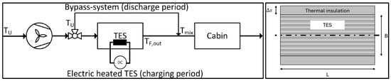
Figure 1.
Power-to-Heat concept for heat supply in electric vehicles using a directly electrically heated solid media TES (charging period) and a bypass system (discharge period) [14], and schematic cross-sectional illustration of the TES with thermal insulation of thickness .
During the discharging phase, the stored thermal energy is used to heat the vehicle cabin. To achieve this, incoming ambient air () is split by a controllable bypass system: one portion flows through the TES, while the other bypasses it. By mixing the hot air stream () with ambient air () downstream, a defined supply temperature () can be delivered to the cabin. Such a solid media thermal storage system, in which the storage material is in direct contact with the flowing heat transfer fluid, is referred to as a regenerator [16,17]. This type of system is commonly used in high-temperature applications with operating temperatures exceeding 1000 °C.
The TES is designed to be charged during stationary vehicle charging, i.e., simultaneously with the traction battery from a grid connection. Heat is generated directly within the ceramic storage inventory through electrical resistance heating. For the electrode connection, a parallel configuration is employed, in which airflow and current path run parallel to each other, with electrical contact established at the open front faces of the honeycomb structure.
To evaluate the proposed storage concept, the temperature-dependent specific electrical resistance of various SiC-based high-temperature materials was determined, as it strongly affects heating performance. As the chosen honeycomb structures can be manufactured using both conventional and additive manufacturing techniques, a broad selection of suitable materials is possible. Simulation studies were then conducted to identify design solutions enabling both efficient electrothermal charging and thermal discharging under given boundary conditions (e.g., grid voltage, maximum current, and power limits). Key performance indicators such as energy density, charging duration, and pressure drop were used for evaluation. Additionally, suitable materials for the electrode connection were experimentally examined regarding contact resistance and high-temperature stability. The simulation models used are described in detail in Section 3.
3. Modeling
3.1. Tortuosity
Detailed modeling of porous structures such as honeycombs, including the associated heat transport mechanisms and electrical current paths, would significantly increase modeling and simulation effort. To capture such design-relevant aspects, a geometric parameter—the tortuosity —is implemented. Tortuosity captures the influence of complex porous structure on transport processes and expresses the ratio of the actual transport properties (e.g., effective electrical resistivity or thermal conductivity) to the intrinsic bulk values of the solid material, thus avoiding the need for a detailed geometric representation [18,19].
For the parallel electrode configuration, the correlation for tortuosity is derived using the approach in [19] and is given by Equation (1):
Here, is the void fraction, defined as the ratio of void volume to total volume. Tortuosity, as a dimensionless parameter, is scale-independent and remains unaffected by changes in specific surface [19].
Accordingly, the effective transport properties are calculated as:
where and denote the intrinsic thermal conductivity and electrical resistivity of the solid material, respectively, and and represent the effective values used in the thermal model (Section 3.2) and the electrothermal model (Section 3.3), respectively. Figure 2 exemplarily shows the tortuosity as a function of the void fraction for a honeycomb structure with quadratic flow channels.
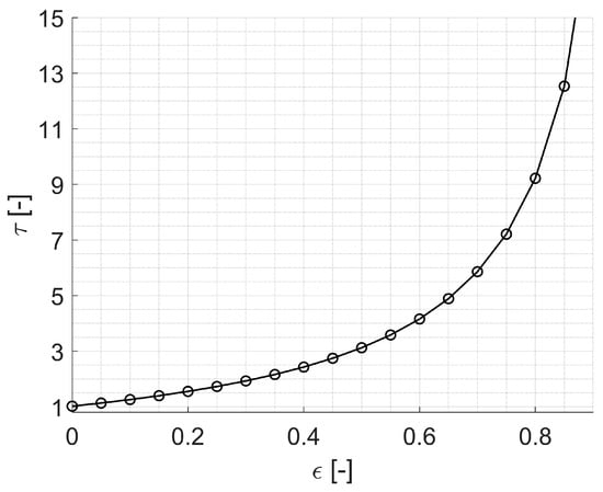
Figure 2.
Tortuosity as a function of void fraction for a honeycomb structure with quadratic flow channels.
3.2. Solid Media Thermal Energy Storage System
During the discharge period, ambient air flows through the TES system, absorbs heat from the electrically preheated solid medium, and is then mixed at the outlet via a bypass to achieve the desired temperature (see Figure 1). To model the transient behavior of sensible solid media TES systems during the discharge phase, a heterogeneous porous continuum approach is used, providing the temporal and spatial temperature distribution of the gaseous phase (F) and the solid phase (S) [20]. Due to the high thermal conductivity of the solid medium, the uniform flow distribution at the inlet, and the low heat losses through the surrounding walls, radial gradients along the flow direction can reasonably be neglected. In addition, the axial heat conduction term for the fluid can be omitted, since the thermal conductivity of the fluid phase is low compared to the convective part. As a result, the system can be described by one-dimensional heat balance equations in time and space :
Solid
Fluid
In addition to the transient heat balance equations, the following boundary conditions are defined:
Solid
Fluid
In this context, and denote the temperatures of the solid and fluid phase, respectively. The parameter represents the fluid velocity, the void fraction, and the specific heat transfer surface of the inventory and the casing wall, both related to the total storage volume (fluid and solid). The density , the specific heat capacity , and the thermal conductivity of air are calculated and temperature-averaged using a real gas model by Lemmon [21]. The total regenerator heat transfer coefficient is calculated according to Hausen, including the heat resistance inside the solid phase as well as the heat transfer coefficient of the fluid for the investigated channel-shaped geometry [22,23]. Thermal losses through the insulation are implemented by in the heat balance equations and by the solid phase boundary conditions, assuming free convection at the outer surface to the ambient. For the density , the specific heat capacity , and the thermal conductivity temperature-averaged material quantities are used. The temperature-averaged effective thermal conductivity is calculated using Equation (2). Equations (4) and (5) are discretized in space using central and backward finite differences for the solid and fluid phase, respectively. The resulting set of differential algebraic equations, including the boundary conditions, is solved in time with MATLAB (R2020a, MathWorks).
3.3. Electrical Heating
The TES is directly heated electrically, with the resulting heating power determined by Ohm’s law from current and voltage. The charging process is modeled using an electrothermal 0D model that incorporates the temperature-dependent specific electrical resistivity and is expressed in Equation (9):
Here, is the storage mass, the electrical power, the thermal losses through the insulation, the electrical voltage, the electrical resistance, the cross-sectional area of the storage perpendicular to the current flow, and the storage length. The specific electrical resistivity is accounted for using parameterized equations derived from experimental studies (see Section 4.1). The geometric influence on the effective ohmic resistance of the porous structure is captured by the tortuosity , which is integrated into the electrothermal model using Equation (3). The model assumes ideal electrode contact, defined as a full-surface, symmetrical connection without contact resistance, ensuring a homogeneous current density across the cross-section. The model equation is solved in MATLAB.
4. Experimental Material Characterization and Contact Resistance
4.1. Material Screening Based on Electrical Resistivity
A prerequisite for designing a directly heated SiC-based storage system is detailed knowledge of the temperature dependence of the specific electrical resistivity. For this reason, the electrical properties of various SiC-based materials were experimentally measured from 20 °C to 1000 °C. The investigated materials were grouped into three categories based on their composition: (1) silicon-infiltrated SiC (SiSiC) from different manufacturers, (2) SiC modified with varying amounts of electrically conductive additives, and (3) SiC-based composites with variable phase ratios. Detailed compositional data cannot be disclosed due to confidentiality agreements. For reference, the resistivity of typical metallic heating wires (e.g., FeCrAl) is included.
The specific electrical resistivity of the SiC-based specimens was determined using the four-point probe method. Bar-shaped samples with a length-to-cross-section ratio of 4–5 were used to ensure homogeneous current distribution. Electrical contacts were attached via four platinum wires fixed with a graphite-based adhesive. The experimental setup for electrical characterization, including the contacting principle, the four-point measurement configuration, and a photograph of a contacted specimen, is shown in Figure 3.
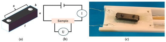
Figure 3.
Experimental setup for electrical characterization: (a) schematic of the sample contacting principle with length , cross-sectional dimensions , , and electrode spacing ; (b) schematic of the four-point measurement configuration; (c) photograph of a contacted specimen with four platinum wires fixed using a graphite-based adhesive. © Fraunhofer-Gesellschaft, used with permission.
The measurements were conducted in an argon atmosphere to prevent oxidation at high temperatures. The temperature was controlled with a laboratory tube furnace, and the electrical resistance was recorded as a function of temperature. Based on the measured resistance and the sample geometry (cross-sectional dimensions , , and electrode spacing ), the specific electrical resistivity was calculated according to Equation (10):
The results of the experimental determination of the temperature-dependent specific electrical resistivity are shown in Figure 4. For each material, the plotted value represents the average specific resistivity over the full temperature range from 20 °C to 1000 °C.
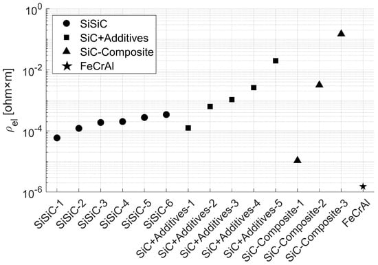
Figure 4.
Average specific electrical resistivity of SiC-based materials from 20 °C to 1000 °C.
As shown in Figure 4, the 3D-printable SiSiC variants exhibit specific electrical resistivity values of approximately to Ωm, mainly due to the relatively high electrical conductivity of the free silicon phase. Nevertheless, SiSiC resistivity remains several orders of magnitude higher than that of conventional metallic heating elements (e.g., FeCrAl). Typical free silicon contents range from 10% to 25% by volume, depending on the manufacturing process and porosity of the initial SiC structure. Higher free silicon fractions result in lower overall resistivity, so samples with lower free silicon content (e.g., SiSiC-6) show higher values.
In contrast, the materials in groups (2) and (3) exhibit a much wider resistivity range due to their compositional flexibility. Electrically doped SiC with conductive additives (group 2) shows values of between and Ωm, primarily controlled by the amount of additive, with lower concentrations yielding higher resistivity. The SiC-based composites (group 3) cover the broadest range, with average values between and Ωm, reflecting the influence of phase composition and microstructure. By adjusting the volume fraction of conductive and non-conductive components, the electrical behavior can be tailored across several orders of magnitude. Moreover, all investigated materials exhibit negative temperature coefficient (NTC) behavior, meaning that resistivity decreases with increasing temperature.
4.2. Material Selection
Before conducting the simulation studies on charging and discharging (Section 5), a suitable material must be selected based on its specific electrical resistivity. For this purpose, the standard grid voltage of 230 V is assumed, which is commonly available in residential environments across Europe. To define a relevant electrical resistance range, an exemplary current of 32 A is considered, reflecting typical limits in electric vehicle infrastructure and domestic energy supply. The corresponding storage resistance is then calculated via Ohm’s law and directly related to material properties and geometry using Equation (9), with averaged over 20 °C to 1000 °C. By introducing the dimensionless length-to-width ratio = L/B and assuming a quadratic cross-section ( = ), the required resistance constrains feasible combinations of length and cross-sectional dimensions. Figure 5 shows, for one representative of each material group, the void fraction and the corresponding length-to-width ratio needed to meet the target resistance range. The isolines represent contours of constant resistance for each material group.
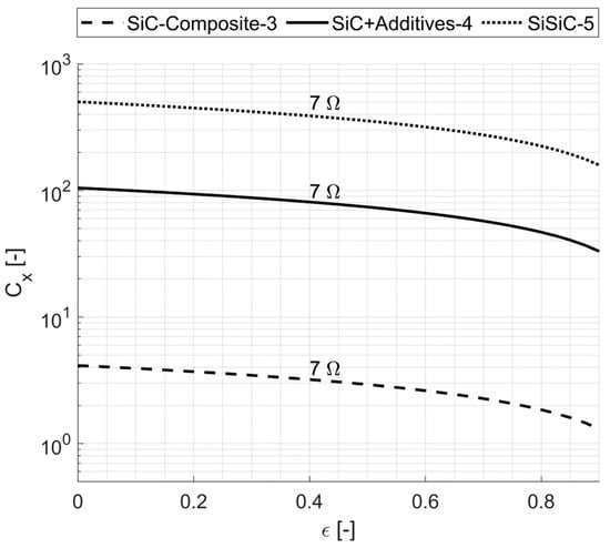
Figure 5.
Isolines of constant electrical resistance as a function of void fraction and length-to-width ratio for one representative material from each of the three SiC-based material groups.
It becomes evident that many SiC-based materials—particularly the 3D-printable SiSiC and electrically doped SiC variants—require very high length-to-width ratios to achieve sufficient electrical resistance. This inevitably results in long, slender geometries that pose significant design challenges: extended flow paths cause substantial pressure losses in the gas flow, and the increased outer surface area leads to larger volumes of thermal insulation. One potential approach to mitigate these issues is to coil or meander the elongated geometries and stack them into planar modules connected electrically in series. This transforms wire-like into plate-like arrangements, reducing insulation demand by creating a more compact geometry. However, it increases fabrication complexity and likely raises total contact resistance due to multiple serial connections. Among the evaluated materials, ‘SiC-Composite-3’, a conventionally manufacturable SiC-based composite, appears most promising, allowing designs with moderate length-to-width ratios ( < 4). Consequently, all subsequent electrothermal charging and thermal discharging calculations were carried out using this material.
4.3. Experimental Investigations on Electrical Contacting
Besides the storage material, reliable high-temperature electrical contacting is a key prerequisite for a directly heated TES system. Poor electrical contacting can lead to high contact resistance, localized overheating, or mechanical degradation. Therefore, contact materials must provide low and stable electrical resistance, even at elevated temperatures, and they must be chemically and mechanically compatible with SiC to prevent interfacial reactions such as silicide formation, which could compromise electrical performance and mechanical integrity [24].
Among potential contacting materials, only aluminum and silver avoid the formation of brittle silicides at the ceramic interface, making them prime candidates for high-temperature SiC applications [24]. Aluminum is commonly used for metallization and electrical contacting, with connection concepts based on aluminum coatings and connector straps considered state of the art for SiC heating elements. However, these concepts are generally limited to operating temperatures below 200 °C due to oxidative degradation. In contrast, silver (Ag) remains stable up to around 700 °C, making it a promising alternative for high-temperature applications.
To examine design-critical aspects such as contact resistance and high temperature stability, laboratory tests were conducted using three cylindrical ‘SiC-Composite-3’ specimens: two with silver-coated end faces and one uncoated reference (see Figure 6).
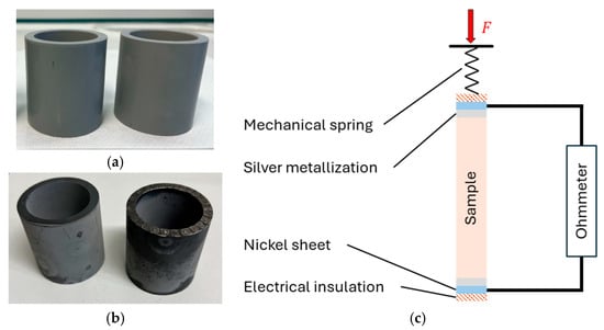
Figure 6.
Test specimens made from ‘SiC-Composite-3’: (a) after green machining; (b) after sintering with (right) and without silver metallization (left); (c) schematic illustration of the experimental setup.
This setup enables a direct comparison of metallized and non-metallized components regarding contact resistance. For this purpose, the tube is clamped at both ends between nickel sheets and electrical insulators, with a defined contact force applied via a mechanical spring. Contact resistance as a function of contact pressure is measured using a DC milliohmmeter (GW Instek, Taipei, Taiwan), which precisely records the total resistance of the setup, including the contact resistance, the intrinsic tube resistance provided by the manufacturer, and the known resistance of the supply lines. To assess the effect of metallization, measurements were performed on samples with and without silver coating under varying contact pressures at room temperature.
The results show that silver-metallized specimens achieved contact resistance values well below 2% of those of non-metallized samples, demonstrating that reliable electrical contact was achieved (see Figure 7).
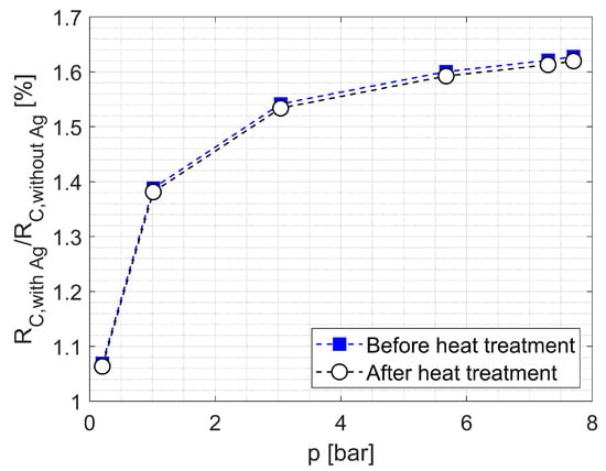
Figure 7.
Ratio of the electrical contact resistance of a silver-metallized ‘SiC-Composite-3’ sample to a non-metallized sample, based on experimental results as a function of contact pressure before and after the heat treatment (700 °C, 5 h).
The increase in the contact resistance ratio between metallized and non-metallized specimens can be explained by the fact that the metallized samples already achieve good initial contact at low pressures. In contrast, the contact quality of the non-metallized sample improves more strongly with increasing pressure—as surface asperities flatten and the real contact area grows—leading to a steeper decrease in its contact resistance compared to the metallized counterpart. At higher pressures, both specimens reach their ‘contact optimum’, and the ratio stabilizes. Complete elimination of contact resistance is not feasible; the residual value of about 2% may be attributed to microscopic surface roughness, suggesting that contact quality could be further improved during manufacturing.
To assess the high-temperature stability of the silver coating, the specimens were placed in a laboratory furnace at 700 °C for 5 h. Subsequent resistance measurements showed no detectable change compared to the initial values, indicating that the silver metallization remains thermally stable up to 700 °C. In summary, silver provides thermally stable electrical contacts with low resistance for moderate high-temperature applications up to 700 °C.
5. Simulation Results and Discussion
Design studies are carried out to identify solutions for the heat supply in BEVs that combine high effective storage density with high charging and discharging power. The approach follows a three-step methodology: (1) thermal design calculations for the discharging process (via bypass operation) with systematically varied key parameters such as void fraction, specific surface, length-to-width ratio, and maximum storage temperature (Section 5.1); (2) evaluation of electrothermal charging (Section 5.2); and (3) identification of design solutions that enable both high storage utilization during thermal discharging and efficient electrothermal charging under the given boundary conditions (e.g., grid voltage, current range). Key performance indicators—energy density, pressure drop, maximum current, and power input limitations—serve as evaluation criteria (Section 5.3).
For the simulation studies, central process specifications, thermal and electrical boundary conditions (Table 1), and material properties (Table 2) are specified. The boundary conditions and target values, including thermal storage capacity (), thermal discharge power (), constant mixing outlet temperature (), ambient temperature (), discharge duration (), and maximum permitted pressure drop (), are based on requirements for cabin heating in BEVs under cold environmental conditions [14,25]. Thermal insulation design assumes a maximum surface temperature of 60 °C () to ensure passenger safety. A grid voltage of 230 V is selected, as it is widely available in residential settings and commonly provided at standard charging stations, ensuring high accessibility. A maximum current of 32 A is defined as an evaluation criterion, reflecting typical limits in electric vehicle infrastructure and domestic energy supply.

Table 1.
Boundary conditions and target values [14,25].
Table 2.
Temperature-averaged material properties of the solid media and the thermal insulation, exemplarily shown for the range from −10 °C to 700 °C.
The material properties of the solid media and thermal insulation were averaged over temperature and are listed in Table 2. A microporous insulation material [26] was used due to its low thermal conductivity and density, making it suitable for compact insulation even at high temperatures.
5.1. Thermal Discharge
During the discharge period, the total mass flow is split into a bypass flow and a flow through the thermal storage unit in order to compensate for the temporal decrease in the fluid outlet temperature including heat losses and thus to achieve a constant mixing temperature. To identify thermally efficient design with high effective storage densities, parameter variations were carried out on geometry and storage temperature. The parameter space included a length-to-width ratio of 0.5–4, specific surfaces of 50–600 m2/m3, void fractions of 0.2–0.7, and maximum storage temperatures of 400–1000 °C. To ensure constant discharge power over the discharge period of 30 min (Table 1), the storage mass was iteratively adjusted. By the end of discharge, 100% of the mass flow passes through the TES unit. Figure 8 shows the resulting effective gravimetric and volumetric thermal energy densities, including storage utilization (defined as the ratio of usable to maximum stored thermal energy).
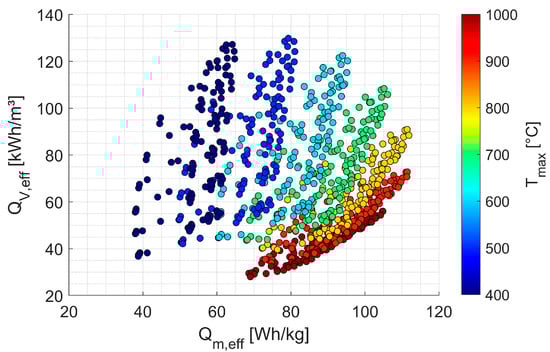
Figure 8.
Effective gravimetric and volumetric thermal energy density, including storage utilization during the discharge period of the ‘SiC-Composite-3’, as a function of maximum storage temperature.
The results reveal a wide range of possible energy densities, arising from variations in storage dimensions (), void fraction (), specific surface (), and maximum storage temperature (). Maximum gravimetric and volumetric energy densities occur at specific storage temperatures due to opposing effects: higher temperatures increase the energy density of the solid storage medium and reduce the required storage mass and volume, but simultaneously demand thicker thermal insulation to maintain the maximum permitted outer surface temperature of 60 °C. A maximum gravimetric energy density of about 110 Wh/kg is reached at 800 °C, while the maximum volumetric energy density (about 130 kWh/m3) occurs at 500 °C.
The influence of storage dimensions, void fraction, and specific surface on thermal utilization is shown in Figure 9.
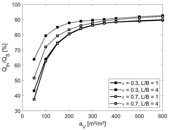
Figure 9.
Storage utilization as a function of specific surface (), void fraction () and length-to-width ratio (), evaluated at an exemplary maximum storage temperature of 700 °C.
It can be seen that higher specific surfaces significantly enhance storage utilization. Further moderate improvements are also achieved by increasing the length-to-width ratio ( = L/B) and by decreasing the void fraction, as this leads to higher total heat transfer coefficients due to increased flow velocities. In summary, a specific surface of at least 200 m2/m3 and small void fractions are required to reach storage utilization of up to 90%, and thus high effective storage densities.
Based on the solutions shown in Figure 8, the highest effective gravimetric energy densities for the selected material occur at storage temperatures of about 800–900 °C, while the maximum volumetric energy density occurs around 500 °C. As a compromise, a maximum storage temperature of 700 °C is chosen, allowing gravimetric energy densities close to their maximum while keeping volumetric energy density only moderately below its peak. Accordingly, a target temperature of 700 °C at the end of the charging process is used for the subsequent electrothermal charging design calculations.
5.2. Electrothermal Charging
Using Equation (9), along with the voltage specified in Table 1, the geometric dimensions of the cuboid honeycomb structure from the thermal calculations, and the material properties of ‘SiC-Composite-3’ (Table 2), the charging duration (), average current, and corresponding average electrical power during heating up to a storage temperature of 700 °C are calculated.
Figure 10 (left) shows the variation in average electrical power as a function of the storage dimensions and the void fraction . According to Equation (9), both parameters are directly linked to the effective electrical resistance of the structure and thus to the resulting electrical power. The wide range of average electrical power arises from different geometric dimensions of the designs: longer and more slender geometries and/or larger void fractions increase the electrical resistance of the structure, which, for a given voltage, reduce current and consequently electrical power. However, in addition to the storage dimensions and void fraction, the thermal utilization coefficient strongly depends on the specific surface. A low thermal utilization coefficient requires a larger storage mass to discharge the same amount of thermal energy, increasing the charging duration because more mass must be heated to the target temperature. Conversely, higher specific surfaces improve thermal utilization and thus shorten the charging duration (Figure 10, right).
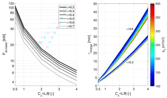
Figure 10.
Average electrical power as a function of storage dimensions and void fraction ε (left), and the resulting charging durations (right), shown for ‘SiC-Composite-3’.
The following section combines the charging and discharging results to identify design solutions that are efficient in both modes while meeting key performance criteria and specified target values.
5.3. Selection of a Design Concept at 700 °C
To evaluate the potential of the proposed concept, design solutions must be identified that enable both efficient electrothermal charging and thermal discharging. Evaluation criteria include gravimetric and volumetric energy density, pressure drop, maximum current/power limits, and charging duration. Starting from the solution space at a storage temperature of 700 °C (Figure 11, left), applying the target criteria—a maximum pressure drop of 15 mbar and maximum current levels up to 32 A (~7.4 kW, see Table 1)—progressively reduces the solution space from left to right.
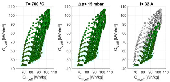
Figure 11.
Reduction in the solution space at 700 °C and 230 V under the applied target criteria—solutions that do not meet the target criteria are shown in gray.
The remaining region, representing the highest achievable gravimetric and volumetric energy densities along with the corresponding void fractions, storage dimensions, charging durations, and specific surfaces, is shown in Figure 12.
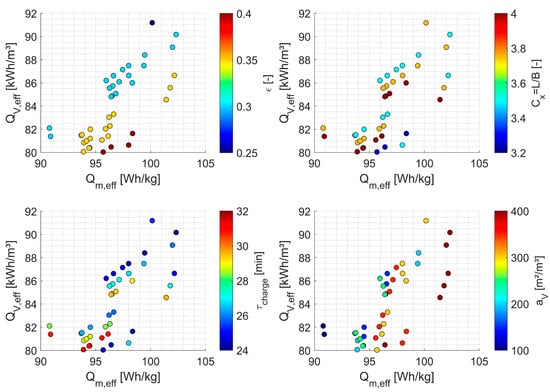
Figure 12.
Achievable gravimetric and volumetric energy densities at 700 °C and 230 V under the applied target criteria.
The results in Figure 12 indicate that elongated storage designs with a length-to-width ratio greater than 3.2 are necessary to comply with the maximum current and power limits. Configurations with low void fractions and high length-to-width ratios, however, produce unacceptably high pressure drops. Remaining designs require a greater volume of thermal insulation due to their larger outer surface area, which in turn reduces the achievable energy density.
Figure 13 shows, for one exemplary solution, the time-dependent mass flow through the TES and the temperature of the fluid exiting the storage. The selected concept variant has a length of 0.42 m, a width of 0.12 m, a void fraction of 30%, and a specific surface of 400 m2/m3.
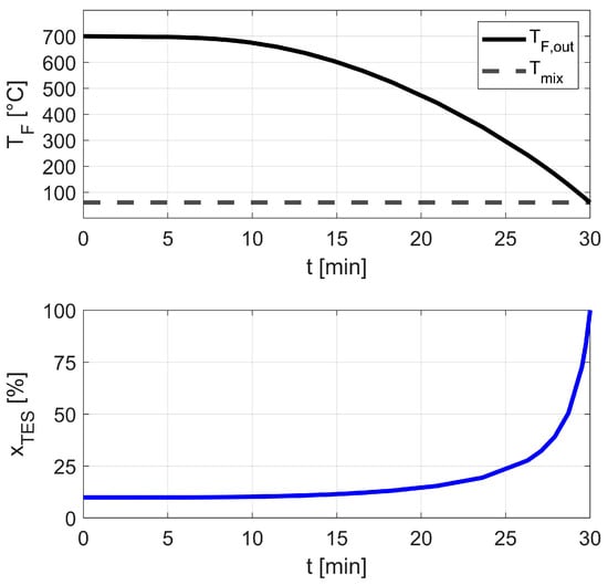
Figure 13.
Time-dependent mass flow through the storage system, relative to the total mass flow, and fluid outlet temperature.
As the TES outlet temperature decreases over time, a larger fraction of the total mass flow must be directed through the TES to maintain the target mixing outlet temperature. For the characteristics shown, the TES exhibits a maximum pressure drop of 13.1 mbar and achieves a thermal utilization of 88.9%, resulting in effective gravimetric and volumetric energy densities of 102 Wh/kg and 90 kWh/m3, respectively. The corresponding charging time is about 24 min at an electrical input power of 7 kW. A thermal discharge power of 5 kW is achieved, with the bypass system offering excellent scalability: lower discharge power requirements allow proportionally longer discharge durations. For the selected design, a TES mass of only 18 kg is required, with the thermal insulation (thickness of 55 mm) adding another 6 kg. During a 12 h standby period with a TES surface temperature of 60 °C and an ambient temperature of –10 °C, heat losses amount to roughly 26% of the stored energy. This corresponds to a conservative worst-case scenario, as in practice the TES can be charged shortly before departure, leading to lower standby losses.
Overall, these holistic results indicate the high potential of an electrically directly heated solid media TES system with a bypass and demonstrate its feasibility for application in BEVs. For larger storage systems (e.g., in buses), where insulation mass is small relative to total system mass, even higher effective energy densities can be achieved, as the storage medium alone provides about 140 Wh/kg. Compared to previously investigated concepts—such as electrically non-conductive ceramic honeycombs with embedded metallic resistance wires (indirect resistance heating) or PCM-based TES systems (e.g., Al–Si alloy) [4,13]—the present approach yields lower energy densities, mainly due to the relatively low specific heat capacity of the selected material (‘SiC-Composite-3’).
Future advances in material development—toward higher specific heat capacities and higher resistivity—offer considerable potential for improvement. Particularly promising are materials with comparable electrical properties that also exhibit PTC behavior. Combined with the growing availability of 3D-printing techniques, such materials could enable controlled redistribution of current: as resistance increases with temperature, current is forced through alternative paths. By tailoring the hole pattern of the structure, this effect can be harnessed to increase overall resistance. Another approach for geometric optimization is the use of TPMS (Triply Periodic Minimal Surfaces) structures, which could significantly improve thermal performance due to their high surface-to-volume ratios, enabling more compact designs [27]. In addition to the current concept, where airflow and current path are parallel, perpendicular arrangements—where airflow and current path are arranged orthogonally—could represent an alternative optimization strategy.
Future work will focus on setting up a test rig of the complete system at the target scale to provide an experimental proof of concept and generate data for validating the developed models. The experiments will also include cyclic operation to assess the long-term stability of the material and provide insights into overall system reliability.
6. Conclusions
To improve the driving range of BEVs in cold seasons, this study introduces a novel thermal management concept based on a directly electrically heated sensible solid media TES system with high-temperature insulation and a controllable bypass system. To assess the feasibility of this concept, key questions were addressed regarding material selection for both the storage medium and electrode contacts, as well as the overall storage design. Based on exemplary specifications for cabin heating, the proposed system enables high discharging powers (constant 5 kW for 30 min), achieves high thermal utilization of up to 90%, and shows gravimetric and volumetric energy densities—including thermal insulation demand—exceeding 100 Wh/kg and 90 kWh/m3, respectively. Reliable operation of the selected SiC-composite material up to 700 °C with a silver metallization for electrode connections, as well as fast charging from a standard grid connection (230 V, ≤32 A) in about 25 min, is feasible, with the battery charging time only marginally increased when the TES is charged in parallel.
Although alternative thermal storage technologies, such as PCM-based or solid media-based TES systems with indirect resistance heating, can currently achieve higher storage densities, the proposed concept offers distinct advantages. Unlike PCM-based systems, no additional effort is required for heat transfer structures due to the direct contact between storage and heat transfer medium. Compared to concepts with indirect resistance heating, eliminating metallic heating wires enhances durability at high temperatures by avoiding oxidation issues and simultaneously reduces assembly complexity. In addition, direct electrical heating allows for homogeneous heating, helping to avoid hotspots and minimize thermally induced stresses.
In comparison with state-of-the-art lithium-ion batteries, which currently power PTC heaters and provide effective energy densities of about 100–180 Wh/kg [7], this novel concept of a directly heated solid media TES system shows competitive first results and demonstrates that the basic prerequisites for such storage systems in BEVs are met. However, further advances in material development—toward higher specific heat capacities, higher specific electrical resistances, and additive manufacturability—are needed to fully unlock its potential. Additional optimization could be achieved with materials exhibiting PTC behavior, enabling the effective electrical resistance to be tuned via structural design.
Future work will focus on building a test rig of the complete system at the target scale to provide experimental proof of concept and to validate the developed models under realistic cyclic conditions.
Author Contributions
Conceptualization, T.O.; methodology, T.O. and V.D.; software, T.O.; writing—original draft preparation, T.O.; writing—review and editing, V.D.; visualization, T.O.; supervision, V.D. All authors have read and agreed to the published version of the manuscript.
Funding
This research received no external funding.
Data Availability Statement
The original contributions presented in this study are included in the article. Further inquiries can be directed to the corresponding author.
Conflicts of Interest
The authors declare no conflicts of interest.
Abbreviations
The following abbreviations are used in this manuscript:
| BEVs | Battery Electric Vehicles |
| FeCrAl | Iron–Chromium–Aluminum |
| NTC | Negative Temperature Coefficient |
| PCM | Phase Change Material |
| PTC | Positive Temperature Coefficient |
| SiC | Silicon Carbide |
| SiSiC | Silicon-infiltrated Silicon Carbide |
| TES | Thermal Energy Storage |
| TPMS | Triply Periodic Minimal Surfaces |
References
- Henning, M.; Smyth, A.; Thomas, A.R. An Analysis of the Association Between Changes in Ambient Temperature, Fuel Economy, and Vehicle Range for Battery Electric and Fuel Cell Electric Buses; Cleveland State University: Cleveland, OH, USA, 2019. [Google Scholar]
- Kuper, C.; Hoh, M.; Houchin-Miller, G.; Fuhr, J. Thermal Management of Hybrid Vehicle Battery Systems; EVS24: Stavanger, Norway, 2009. [Google Scholar]
- Knote, T. E-Bus-Standard: “Ansätze zur Standardisierung und Zielkosten für Elektrobusse”; Fraunhofer-Institut für Verkehrs- und Infrastruktursysteme (IVI): Dresden, Germany, 2017. [Google Scholar]
- Luo, C.; Xie, P.; Chen, G.; Mao, L.; Liu, L.; Jin, L.; Cheng, Z.; Xu, J.; Qiao, G. Prototype design and experimental study of a metal alloy-based thermal energy storage system for heat supply in electric vehicles. J. Energy Storage 2022, 51, 104393. [Google Scholar] [CrossRef]
- Wang, M.; Wolfe, E.; Craig, T.; LaClair, T.J.; Gao, Z.; Abdelaziz, O. Design and Testing of a Thermal Storage System for Electric Vehicle Cabin Heating. In Proceedings of the SAE World Congress, Detroit, MI, USA, 12–14 April 2016. [Google Scholar]
- Uğurlu, A.; Gökçöl, C. A Review on Thermal Energy Storage Systems with Phase Change Materials in Vehicles. Electron. J. Vocat. Coll. 2012, 2, 1–14. [Google Scholar]
- Kraft, W.; Stahl, V.; Vetter, P. Thermal Storage Using Metallic Phase Change Materials for Bus Heating—State of the Art of Electric Buses and Requirements for the Storage System. Energies 2020, 13, 3023. [Google Scholar] [CrossRef]
- Xie, P.; Jin, L.; Qiao, G.; Lin, C.; Barreneche, C.; Ding, Y. Thermal energy storage for electric vehicles at low temperatures: Concepts, systems, devices and materials. Renew. Sustain. Energy Rev. 2022, 160, 112263. [Google Scholar] [CrossRef]
- Diaconu, B.; Cruceru, M.; Anghelescu, L.; Racoceanu, C.; Popescu, C.; Ionescu, M.; Tudorache, A. Latent Heat Storage Systems for Thermal Management of Electric Vehicle Batteries: Thermal Performance Enhancement and Modulation of the Phase Transition Process Dynamics: A Literature Review. Energies 2023, 16, 2745. [Google Scholar] [CrossRef]
- Dolla, D.A.; Fetene, M.G. Investigations of phase change materials in battery thermal management systems for electric vehicles: A review. Mater. Res. Express 2024, 11, 012002. [Google Scholar] [CrossRef]
- Dieterich, M.; Bürger, I.; Linder, M. Open and closed metal hydride system for high thermal power applications: Preheating vehicle components. Int. J. Hydrogen Energy 2017, 42, 11469–11481. [Google Scholar] [CrossRef]
- Wilks, M.; Wang, C.; Ling-Chin, J.; Wang, X.; Bao, H. Thermochemical energy storage for cabin heating in battery powered electric vehicles. Energy Convers. Manag. 2023, 291, 117325. [Google Scholar] [CrossRef]
- Dreißigacker, V.; Hofer, L. High-Performance Solid Medium Thermal Energy Storage System for Heat Supply in Battery Electric Vehicles: Proof of Concept and Experimental Testing. Appl. Sci. 2022, 12, 10943. [Google Scholar] [CrossRef]
- Belik, S.; Dreißigacker, V.; Kölbig, M.; Kraft, W. Thermal Energy Storage Systems: Power-to-Heat Concepts in Solid Media Storage for High Storage Densities. J. Traffic Transp. Eng. 2017, 5, 285–294. [Google Scholar] [CrossRef][Green Version]
- Anwar, M.S.; Bukhari, S.Z.A.; Ha, J.-H.; Lee, J.; Song, I.-H.; Kim, Y.-W. Controlling the electrical resistivity of porous silicon carbide ceramics and their applications: A review. Int. J. Appl. Ceram. Technol. 2022, 19, 1814–1840. [Google Scholar] [CrossRef]
- Turner, R.H. High-Temperature Thermal Energy Storage: Including a Discussion of TES Integrated into Power Plants; Franklin Institute Press: Philadelphia, PA, USA, 1977. [Google Scholar]
- Dincer, I.; Rosen, M.A. Thermal Energy Storage: Systems and Applications; John Wiley & Sons: Chichester, UK, 2021. [Google Scholar]
- Ghanbarian, B.; Hunt, A.G.; Ewing, R.P.; Sahimi, M. Tortuosity in Porous Media: A Critical Review. Soil Sci. Soc. Am. J. 2013, 77, 1461–1477. [Google Scholar] [CrossRef]
- Ott, T.; Dreißigacker, V. Electrical Tortuosities of Porous Structures Based on Triply Periodic Minimal Surfaces and Honeycombs for Power-to-Heat Systems. Energies 2024, 17, 5781. [Google Scholar] [CrossRef]
- Ismail, K.A.R.; Stuginsky, R., Jr. A parametric study on possible fixed bed models for PCM and sensible heat storage. Appl. Therm. Eng. 1999, 19, 757–788. [Google Scholar] [CrossRef]
- Lemmon, E.W.; Jacobsen, R.T.; Penoncello, S.G.; Friend, D.G. Thermodynamic Properties of Air and Mixtures of Nitrogen, Argon, and Oxygen From 60 to 2000 K at Pressures to 2000 MPa. J. Phys. Chem. Ref. Data 2000, 29, 331–385. [Google Scholar] [CrossRef]
- Hausen, H. Wärmeübertragung im Gegenstrom, Gleichstrom und Kreuzstrom; Springer: Berlin/Heidelberg, Germany, 1976. [Google Scholar]
- Schmidt, F.W.; Willmott, A.J. Thermal Energy Storage and Regeneration; Hemisphere Publishing Corporation/McGraw-Hill Book Company: New York, NY, USA, 1981. [Google Scholar]
- Hattali, M.L.; Valette, S.; Ropital, F.; Stremsdoerfer, G.; Mesrati, N.; Tréheux, D. Study of SiC–nickel alloy bonding for high temperature applications. J. Eur. Ceram. Soc. 2009, 29, 813–819. [Google Scholar] [CrossRef]
- Kraft, W.; Jilg, V.; Klein Altstedde, M.; Lanz, T.; Vetter, P.; Schwarz, D. Thermal High Performance Storages for Use in Vehicle Applications. In Energy and Thermal Management, Air-Conditioning, and Waste Heat Utilization; Junior, C., Dingel, O., Eds.; Springer: Cham, Switzerland, 2018. [Google Scholar]
- SILCAPOR: Microporous Insulating Board. Available online: http://www.silca-online.de/en/thermal-insulation/insulation-boards/silcapor.html (accessed on 2 September 2025).
- Liu, J.; Cheng, D.; Oo, K.; Pan, W.; McCrimmon, T.-L.; Bai, S. Optimization of Triply Periodic Minimal Surface Heat Exchanger to Achieve Compactness, High Efficiency, and Low-Pressure Drop. Energies 2024, 17, 5141. [Google Scholar] [CrossRef]
Disclaimer/Publisher’s Note: The statements, opinions and data contained in all publications are solely those of the individual author(s) and contributor(s) and not of MDPI and/or the editor(s). MDPI and/or the editor(s) disclaim responsibility for any injury to people or property resulting from any ideas, methods, instructions or products referred to in the content. |
© 2025 by the authors. Licensee MDPI, Basel, Switzerland. This article is an open access article distributed under the terms and conditions of the Creative Commons Attribution (CC BY) license (https://creativecommons.org/licenses/by/4.0/).