Abstract
Due to post-cementing hydraulic fracturing and other operational stresses, inadequate mechanical properties or suboptimal design of the cement sheath can lead to tensile failure and microcrack development, compromising both hydrocarbon recovery and well integrity. In this study, three field-deployed cement slurry systems were compared on the basis of their basic mechanical properties such as compressive and tensile strength. Laboratory-scale physical simulations of hydraulic fracturing during shale oil production were conducted, using dynamic permeability as a quantitative indicator of integrity loss. The experimental results show that evaluating only basic mechanical properties is insufficient for cement slurry system design. A more comprehensive mechanical assessment is re-quired. Incorporation of an expansive agent into the cement slurry system can alleviate the damage caused by the microannulus to the interfacial sealing performance of the cement sheath, while adding a toughening agent can alleviate the damage caused by tensile cracks to the sealing performance of the cement sheath matrix. Through this research, a microexpansive and toughened cement slurry system, modified with both expansive and toughening agents, was optimized. The expansive agent and toughening agent can significantly enhance the shear strength, the flexural strength, and the interfacial hydraulic isolation strength of cement stone. Moreover, the expansion agents mitigate the detrimental effects of microannulus generation on the interfacial sealing, while the toughening agents alleviate the damage caused by tensile cracking to the bulk sealing performance of the cement sheath matrix. This system has been successfully implemented in over 100 wells in the GL block of Daqing Oilfield. Field application results show that the proportion of high-quality well sections in the horizontal section reached 88.63%, indicating the system’s high performance in enhancing zonal isolation and cementing quality.
1. Introduction
The petroleum industry is facing a situation where conventional resources are increasingly scarce, which means that drilling depths will be greater, and working conditions will be more challenging. The extraction of deep unconventional oil and gas re-sources requires dealing with complex conditions such as high temperatures, high pressures, and strong alternating loads, as well as high temperature differences and stresses brought about by hydraulic fracturing, staged fracturing, and large-scale production. Therefore, ensuring the long-term integrity of the cement sheath throughout its lifecycle becomes even more important [1,2,3]. With the continuous advancement of exploration and development, an increasing number of shale oil reservoirs characterized by ultra-low permeability and nanoscale pore throats are being exploited. Conventional recovery methods are largely ineffective in extracting hydrocarbons from these tight formations. As a critical stimulation technique, hydraulic fracturing enhances reservoir permeability by injecting high-pressure fluid into geological formations to create artificial fracture networks and conductive pathways, thereby facilitating hydrocarbon migration through the rock matrix. The cement sheath, serving as a primary barrier in well integrity engineering, performs essential functions including zonal isolation of hydrocarbon- and water-bearing strata, mechanical support for casing strings, and extension of wellbore service life. However, during hydraulic fracturing operations, cement sheath integrity may be compromised due to inadequate mechanical properties of the cementitious material or suboptimal design. These shortcomings hinder the cement sheath’s ability to accommodate cyclic stress variations within the casing system, potentially leading to tensile failure of the cement matrix, development of micro-annulus, and loss of hydraulic isolation. Such integrity failures negatively impact hydrocarbon recovery efficiency and operational safety and may result in sustained casing pressure (SCP) and annular pressure buildup. To meet the performance requirements under complex downhole conditions, the evaluation and optimization of cement sheath integrity primarily rely on theoretical modeling and laboratory experiments, with particular emphasis on laboratory-scale assessment.
Computational models have progressed from assuming homogeneous formation to accounting for heterogeneous formation and from analyzing single-factor temperature [4,5,6] or pressure [7] effects to incorporating coupled multi-physics interactions [8,9,10,11,12,13]. Lullo, Singh et al. investigated cement sheath failure modes under hydraulic fracturing conditions using stress-based analytical models. Their research highlighted that cement ductility, rather than compressive strength, is more critical for maintaining long-term zonal isolation and mechanical integrity of cement sheath [14,15,16,17]. Fan et al. developed finite element models to simulate interfacial crack propagation at casing-cement interfaces, demonstrating that increasing the cement’s elastic modulus and interfacial bond strength effectively reduces crack propagation lengths [18]. Xu et al. established a finite element model for the formation of the plastic zone in the cement sheath during the high-temperature cycling process. They proposed a cement sheath damage variable to define the elastic-plastic transition process of the wellbore interface, quantified the interface debonding and micro-wellbore size caused by thermal stress cycling, and clarified the influence of key parameters such as steam injection temperature, cycling times, and the mechanical properties of the cement sheath on the change in interface integrity [19]. In laboratory experiments, Su et al. studied the mechanical behavior characteristics of hollow cylindrical cement stone specimens under uniaxial, triaxial, and multiaxial compression [20]. Zhou et al. characterized cement matrix damage mechanisms during fracturing stages through triaxial compression and a cyclic load-unloading test [21]. Wu et al., through simulated zonal isolation experiments, identified tensile cracking and micro-annulus generation induced by plastic deformation as the primary failure modes [22]. The hydraulic fracturing process of shale oil and gas wells subjects the cement sheath to high internal pressure and repeated cyclic loading, resulting in more complex stress states in the cement sheath compared to conventional development scenarios. Current evaluation methods relying solely on theoretical calculations or single-parameter testing are insufficient to meet field application requirements. To date, no comprehensive and effective integrated evaluation methodology has been established to ensure cement sheath integrity during shale oil development and to support safe and efficient operations.
On the basis of previous studies, this paper proposes an evaluation method for optimizing cement slurry systems to ensure in situ cement sheath integrity. The research approach is shown in Figure 1. This optimization evaluation method optimizes and screens the on-site cement slurry system from three aspects: the mechanical properties of cement stone (compressive strength, tensile strength, flexural strength, shear strength, and triaxial strength), the mechanical properties of the cement sheath interface (bonding strength and hydraulic sealing strength), and the sealing performance of the cement sheath. It can effectively optimize and evaluate the on-site ap-plied cement slurry system, thereby improving the cementing quality of shale oil wells.
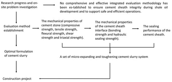
Figure 1.
Research flowchart.
2. Comprehensive Evaluation Method for Cement Slurry Systems
2.1. Development of Evaluation Method
Based on the previous research, this study proposes a comprehensive evaluation method for modified cement slurry systems under hydraulic fracturing conditions (Figure 2). The evaluation framework consists of three main parts: (1) cement stone mechanical property testing (compressive, tensile, flexural, shear, and triaxial strengths), (2) cement sheath interfacial mechanical property testing (interfacial mechanical bonding strength and hydraulic isolation strength), and (3) seal integrity testing of the cement sheath under fracturing conditions. The experimental devices are detailed in Table 1.
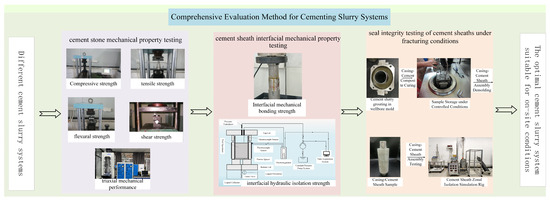
Figure 2.
Comprehensive evaluation method for cement slurry systems.

Table 1.
Experimental devices used in the research.
2.2. Basic Mechanical Testing of Oil Well Cement
Cement specimens were prepared in accordance with API/ISO standards. The cement slurry was formulated following API specifications and cured at 115 °C and 20.7 MPa for 7 days. After cooling and demolding, the mechanical properties were evaluated using a fully automatic electronic servo hydraulic testing machine. Specific test items are detailed in Table 2. Four parallel specimens were prepared for each test parameter, and any outliers were excluded before calculating the average values for data analysis.

Table 2.
Basic mechanical properties testing of cement stone.
2.3. Mechanical Integrity Testing of Cement-Casing Bonding Interface
The mechanical integrity of the cement-casing interface was evaluated by testing both mechanical bonding strength and hydraulic sealing strength. Both tests utilize the same sample configurations, consisting of a cement stone-simulated casing composite to simulate the bonding interface. The simulated casing has an inner diameter of 46 mm, a wall thickness of 2 mm, and a height of 78 mm. The cured cement stone specimen has a height of 65 mm and a diameter of 46 mm. The prepared cement slurry is poured into a molding fixture and cured in a high-pressure high-temperature (HPHT) autoclave at 20.7 MPa and 115 °C for 7 days. The cured specimen is illustrated in Figure 3.
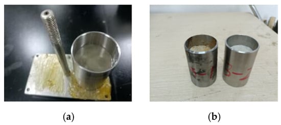
Figure 3.
Specimen preparation for bonding interface mechanical integrity testing. (a) Pouring cement slurry into curing molds, (b) cured test specimens.
(1) The mechanical bonding strength of the cement-casing interface was evaluated using the traditional squeeze-off method, as shown in Figure 4. The mechanical bonding strength is calculated according to Equation (1).
where, F is the peak adhesion rupture force (N), and S is the contact area at the first interface between cement sheath and casing (mm2).
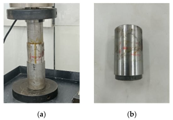
Figure 4.
Evaluation of interface bonding strength in cement stone. (a) Failure interface during loading process, (b)typical interface failure after loading.
(2) The hydraulic isolation strength of the cement stone interface was evaluated using a laboratory-developed testing system (Figure 5). Pressure was applied to the upper end of the specimen via a pressure control device, using water mixed with a tracer dye as the pressurizing medium. The pressure at which stabilization occurs during pressurization was defined as the hydraulic sealing strength of the interface (Figure 6).
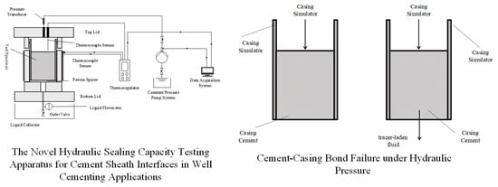
Figure 5.
Cement stone interface sealing performance evaluation system.
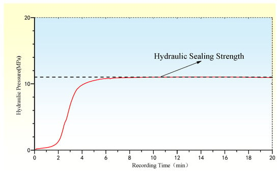
Figure 6.
Typical data analysis of hydraulic sealing strength for cement stone interface.
2.4. Evaluation of Cement Sheath Sealing Integrity Under Simulated Downhole Conditions
The laboratory-scale evaluation of cement sheath sealing performance under simulated downhole conditions involves two primary testing methods: ultimate sealing performance testing and cyclic loading integrity evaluation. The dimensions of the cylindrical test device used in these experiments are listed in Table 3. The experimental workflow includes curing cement sheath-casing assembled specimens, followed by mechanical evaluation under controlled stress regimes. This approach systematically investigates the sealing capacity of cement sheaths, as illustrated in Figure 7, by characterizing both their static sealing limits and dynamic sealing behaviors under repeated load cycles. The method aligns with industry-standard practices for evaluating cement sheath integrity in wellbore systems, with a focus on critical parameters such as annular pressure resistance and fatigue performance under cyclic loading.

Table 3.
Dimensions of laboratory-scale simulated wellbore for experimental testing.
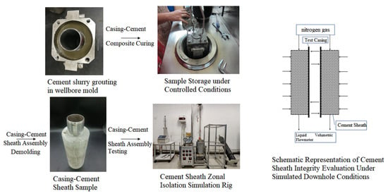
Figure 7.
Experimental workflow for cement sheath sealing integrity evaluation in wellbore condition.
The cement slurry formulation was cured using a composite mold in a high-temperature and high-pressure (HTHP) autoclave at 115 °C and 21 MPa for 7 days. After demolding, the casing-cement sheath composite specimens were installed in an HTHP cement sheath integrity evaluation device to simulate extreme loading c and fracturing conditions. The test principle (Figure 6) involves applying external annulus pressure and internal casing pressure using separate pressure control systems. Nitrogen gas was injected from the upper end of the specimen, and any gas flow at the lower outlet was monitored via a flow monitor. When the cement sheath integrity fails, the monitor will detect gas flow. To evaluate cement sheath damage permeability following damage, matrix permeability was neglected, damaged permeability was calculated using Darcy’s law (Equation (2)), and the Percell method was applied to correct the permeability by Kirkner (Equation (3)), referencing Chinese industry standards DZ/T 0217-2020 “Reserve Estimation Specifications for Petroleum and Natural Gas” [23] (defining reservoirs with air permeability < 1 mD as tight reservoirs) and SY/T 6285-2011 “Methods for Evaluation of Oil and Gas Reservoirs” [24] (classifying K < 1 mD as ultra-low permeability reservoirs). As hydrocarbon migration becomes infeasible below this threshold, it is adopted as the critical standard for cement sheath sealing. Thus, a cement sheath damage permeability < 1 mD ensures that the cement sheath remains an effective barrier during shale oil well operations.
where
is the gas permeability characterization of the damaged cement sheath, mD;
is the atmospheric pressure, MPa;
is the gas flow rate under atmospheric pressure (gas channeling flow rate monitored via flow detection instrumentation), cm3/s;
is the gas dynamic viscosity, ;
is the cement sheath length, cm;
is the cement sheath cross-sectional geometry, cm2;
, are the gas pressure loads on the top/bottom interfaces of the cement sheath, MPa.
where
is the gas permeability characterization of the damaged cement sheath by revised mD;
is the total porosity;
is the average measured pressure, MPa;
is a constant.
(1) In the cement sheath sealing performance ultimate loading experiment, parameters based on the on-site casing parameters (Q125 × 139.7 × 10.54, internal pressure resistance of 113.8 MPa) were used to set a simulated wellhead pressure of 90 MPa, corresponding to a laboratory internal pressure of 92 MPa. The experimental data are shown in Figure 8. During the ultimate loading process, the damage permeability did not increase linearly with the increase in pressure. A sudden change will be observed during the development of the damage permeability, and the pressure at this point is defined as the permeability mutation pressure. The highest measured permeability and its corresponding pressure were recorded as the peak permeability and peak permeability pressure, respectively.
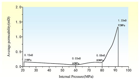
Figure 8.
Typical data analysis of cement sheath permeability under ultimate loading conditions.
Based on the development characteristics of damage permeability, it is known that a higher permeability mutation pressure and peak permeability pressure, as well as a lower peak permeability, indicate better integrity. These parameters were normalized to enable scoring: the normalized pressure = measured pressure/92, and the normalized permeability = 1 − (permeability/1). The sealing performance of the cement sheath under ultimate loading is scored according to the normalization results, as shown in Table 4. If the peak permeability exceeds 1 mD, the test item is scored negatively. A total score of 60 indicates excellent ultimate sealing capacity, assuming the peak permeability remains below 1 mD.

Table 4.
Cement sheath sealing integrity evaluation under extreme loading conditions.
(2) In the cyclic loading experiment of the cement sheath sealing performance, the cyclic loading conditions were determined according to the field operation parameters: internal pressure of 77 MPa (equivalent to a wellhead pressure of 70 MPa), confining pressure of 11 MPa, and 45 loading cycles. During the loading process, if the damage permeability of the cement sheath remained below 1 mD, sealing integrity was considered to be maintained. The test data of the cement sheath sealing performance under cyclic loading are shown in Figure 9. The experiment was divided into three stages: ① initial sealing test, ② cyclic loading test, and ③ post-cyclic sealing test. Since a single permeability measurement cannot fully represent sealing performance, a weighted permeability index was proposed to assess overall performance under cyclic loading conditions. The permeability weighting factors were as follows: initial permeability weighting factor = 0.1 (pre-cyclic loading phase), cyclic permeability weighting factor = 0.5 (during cyclic loading conditions), and post-cyclic permeability weighting factor = 0.4 (post-loading evaluation phase). The weighted permeability is computed using the following equation:
where
is the initial peak permeability of the cement sheath, mD;
is the peak permeability of the cement sheath under cyclic loading conditions, mD;
is the peak permeability following the cyclic loading test, mD;
is the weighted permeability in cement sheath integrity testing, mD.
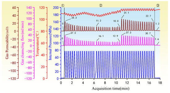
Figure 9.
Typical data analysis of cement sheath systems under simulated fracturing conditions.
3. Case Study
In the shale oil exploitation process within the DB region of China, the implementation of multi-stage hydraulic fracturing imposes strict mechanical and sealing performance requirements on cementing materials. Specifically, the cement stone must exhibit a combination of high-strength and low-elastic modulus to accommodate fracturing-induced stress cycles, while the cement sheath must ensure long-term sealing integrity after multi-stage fracturing. Therefore, a comparative evaluation was conducted on three existing cement slurry systems (Table 5), which are widely used in field operations in this region. The raw materials, including Dalian G-grade oil well cement, quartz sand, expansive agent, toughening agent, and mixing water, were all provided by Daqing Drilling Company.

Table 5.
The experiment involves cement slurry systems.
3.1. Basic Mechanical Analysis of Cement Stone
The compressive, tensile, flexural, and shear strengths of cured cement stone specimens using the three cement slurry systems are illustrated in Figure 10. For Formulation 1, the cement stone exhibits a compressive strength of 30.5 MPa and a tensile strength of 2.8 MPa; Formulation 2 shows a compressive strength of 29.1 MPa and a tensile strength of 2.8 MPa; and Formulation 3 demonstrates a compressive strength of 29.5 MPa and a tensile strength of 2.9 MPa. The compressive and tensile strengths of the three cement slurry systems are comparable. The shear strength of Formulation 1 is 14.1 MPa, while Formulation 2 achieves 25.1 MPa (a 78.0% increase compared to Formulation 1), and Formulation 3 reaches 29 MPa (a 16% increase compared to Formulation 2). For flexural strength, Formulation 1 is 2.7 MPa, Formulation 2 is 3.3 MPa (a 22.2% improvement over Formulation 1), and Formulation 3 is 4.1 MPa (a 24.2% enhancement over Formulation 2). The incorporation of expansive agents and toughening agents in cement slurry systems significantly enhances the shear and flexural strengths.
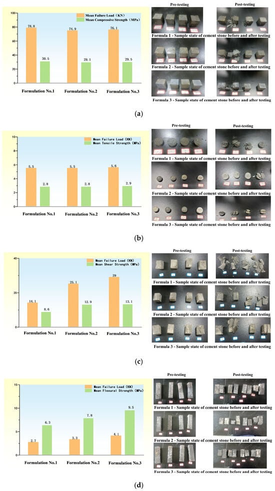
Figure 10.
Basic mechanical properties testing of set cement. (a) Test results of compressive strength of cement stone, (b) test results of tensile strength of cement stone, (c) test results of shear strength of cement stone, (d) test results of flexural strength of cement stone.
3.2. Triaxial Mechanical Behavior Analysis of Cement Stone
Triaxial tests were conducted to evaluate the elastic modulus and Poisson’s ratio of cement stone samples under varying confining pressures (10 MPa, 15 MPa, 20 MPa, and 25 MPa) at a controlled temperature of 115 °C. The results reveal that the elastic modulus decreases with increasing confining pressure for all three formulations. The elastic modulus of the cement stone of Formulation No.1 decreased from 6682.1 MPa to 5394.4 MPa, that of Formulation No.2 decreased from 5975.7 MPa to 4815.0 MPa, and that of Formulation No.3 decreased from 3344.0 MPa to 2528.4 MPa. Notably, Formulation 3—with both expansive and toughening agents—exhibited the lowest elastic modulus across all conditions, indicating enhanced capacity for elastic deformation and better adaptability to dynamic downhole environments. The detailed test data are shown in Table 6.

Table 6.
Test results of triaxial mechanical parameters for oil well cement stone.
3.3. Interface Mechanical Performance Analysis of Cement Sheath
The mechanical bonding strength between the cement stone and casing was tested for all three formulations, with results shown in Table 7. The mechanical bonding strength at the cement stone interface of Formulation 1 is 2.87 MPa, that of Formulation 2 is 3.09 MPa, and that of Formulation 3 is 2.92 MPa. These values are all approximately 3 MPa, indicating minimal influence from the addition of expansive or toughening agents on mechanical interfacial bonding strength. This suggests that such additives do not significantly alter the adhesion between cement surface particles and the casing wall.

Table 7.
Mechanical bonding strength test data of cement matrix.
Hydraulic sealing strength, a critical parameter for maintaining zonal isolation under pressure differentials, was also evaluated (Table 8). The hydraulic sealing strength at the cement stone interface of Formulation 1 is 19.99 MPa, that of Formulation 2 is 20.63 MPa, and that of Formulation 3 is 34.58 MPa. While the expansive agent had limited effect, the inclusion of a toughening agent in Formulation 3 resulted in a more than 70% increase in hydraulic sealing strength compared to the other two. This enhancement is attributed to the toughening agent’s ability to reduce interfacial pore diameter and increase capillary resistance, thereby improving the sealing efficiency of the cement sheath interface.

Table 8.
Experimental evaluation data of cement sheath hydraulic sealing strength.
3.4. Evaluation of Cement Sheath Sealing Performance Under Simulated Operational Conditions
3.4.1. Cement Sheath Sealing Performance Under Ultimate Load Conditions
An indoor experimental scheme was designed according to the field operations. The test parameters simulating the ultimate internal casing pressure loads are shown in Table 9, and the test data of cement sheaths of different systems are presented in Figure 11. For Formulation 1, in the early stage, the internal pressure of the casing increased from 21 MPa to 60 MPa, and the permeability of the cement sheath decreased from 0.15 mD to 0.03 mD, indicating that the cement sheath was compacted during the test. When the internal pressure was between 60 MPa and 80 MPa, the permeability of the cement sheath gradually increased from 0.03 mD to 0.08 mD, suggesting slight damage to the cement sheath. The internal pressure of 80 MPa was the damage inflection point. When the internal pressure increased from 80 MPa to 92 MPa, the permeability of the cement sheath rapidly increased from 0.08 mD to 1.33 mD, and the sealing performance of the cement sheath was severely damaged.

Table 9.
Seal integrity evaluation of cement sheath under laboratory ultimate loading conditions.
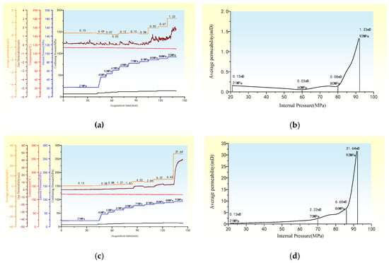

Figure 11.
Test data analysis of cement sheath integrity under ultimate loading conditions in wellbore conditions. (a) Formulation 1 cement sheath ultimate loading conditions raw test data, (b) permeability of Formulation 1 cement sheath under ultimate loading conditions, (c) Formulation 2 cement sheath ultimate loading conditions raw test data, (d) permeability of Formulation 2 cement sheath under ultimate loading conditions, (e) Formulation 3 cement sheath ultimate loading conditions raw test data, (f) permeability of Formulation 3 cement sheath under ultimate loading conditions.
For Formulation 2, a similar trend was observed, but with a delayed damage inflection point at 86 MPa. When the internal pressure was 92 MPa, the permeability reached a peak value of 31.64 mD. For Formulation 3, a lower damage inflection-point pressure was 70 MPa. When the internal pressure was 92 MPa, the peak permeability was limited to 0.22 mD. The increase in the permeability of the cement sheath was not significant, and the sealing performance was damaged to a certain extent.
After the ultimate loading test, the cement sheath specimen was removed and broken for observation. As shown in Figure 12a, the specimen prepared with Formulation 1 exhibited extensive dye infiltration primarily along longitudinal cracks that penetrated through the entire cement sheath. Minimal dye accumulation was observed at the casing–cement sheath interface, indicating that the primary failure mode of the cement sheath was mainly longitudinal penetrating tensile cracks. The cement sheath specimen of Formulation 2 is shown in Figure 12b. The distribution of the dye was similar to that of the cement sheath specimen of Formulation 1, mainly distributed in the cracks of the cement sheath and penetrating the whole cement sheath. The failure mode of the cement sheath was also dominated by longitudinal penetrating tensile cracks. In contrast, the cement sheath specimen of Formulation 3, shown in Figure 12c, exhibited no penetrating cracks. The cement sheath specimen could only be fractured manually by knocking, rather than failing under internal casing pressure. This indicates that the cement sheath still had a certain structural integrity during testing. Dye tracing revealed only minor staining at the casing–cement sheath interface, with no evidence of longitudinal or matrix-scale penetration, suggesting that the interface sealing was still maintained. According to the evaluation method described in Section 2.4, the parameters including permeability change inflection pressure, peak-permeability pressure, and peak permeability during the cement sheath testing process were normalized. Based on these normalized results, a sealing performance score was assigned to each formulation under the ultimate loading condition, as detailed in Table 10. As known from Section 2.4, negative scores would appear when the peak permeability exceeded 1 mD. The prerequisite for the score to reach 60 points was that the peak permeability remain below 1 mD. The sealing integrity score of the cement sheath could not reach 100 points but could only continuously approach 100 points. It was set that under the experimental internal pressure of 21–92 MPa ultimate loading, the cement formulations with scores exceeding 60 points all had excellent ultimate load-bearing capacity. As can be seen from Table 10, only Formulation 3 had excellent ultimate load-bearing capacity.
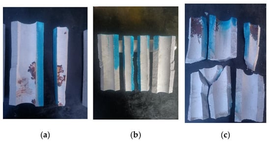
Figure 12.
Post-test specimen of cement sheath under ultimate loading conditions. (a) Formulation No. 1, (b) Formulation No. 2, (c) Formulation No. 3.

Table 10.
Normalized experimental data of cement sheath sealing integrity under ultimate loading condition.
3.4.2. Cement Sheath Sealing Integrity Under Cyclic Loading Conditions
To simulate downhole fracturing conditions, an indoor experimental scheme was designed based on field operations. The test conditions for evaluating cement sheath integrity under cyclic loading are shown in Table 11. The damage test data for various cement formulations are presented in Figure 13. Stage ① initial sealing test: Prior to cyclic loading, each casing–cement sheath assembly underwent a baseline sealing test. No gas-channeling flow was detected in any of the specimens, indicating that all the cement sheaths had good initial sealing performance. Stage ② cyclic loading process: During the first loading cycle, all specimens reached their peak gas-channeling flow rates. For Formulation 1, the gas-channeling peak flow rate was 37.3 mL/min; for Formulation 2, it was 10.5 mL/min; and for Formulation 3, it was 0.8 mL/min. The corresponding damage permeabilities were 24.3 mD, 7.9 mD, and 0.6 mD, respectively. During the subsequent loading process, the cement sheath specimen of Formulation 1 suffered a second damage at the 30th cycle, and the corresponding permeability sharply increased to 31.1 mD. The sealing damage of Formulation 2 and Formulation 3 was basically stable, with the damage permeabilities stabilizing at 4.6 mD and 0.3 mD, respectively. Stage ③ post-cyclic loading test: A secondary sealing evaluation was conducted under the same conditions as the initial sealing test. For Formulation 1, the measured gas-channeling flow rate was 1.6 mL/min, with a corresponding permeability of 1.2 mD. For Formulation 2, the measured gas-channeling flow rate was 0.8 mL/min, with a corresponding permeability of 0.7 mD. For Formulation 3, the measured gas-channeling flow rate was 0.5 mL/min, with a corresponding permeability of 0.3 mD. A detailed data summary and calculated weighted permeabilities are provided in Table 12. As can be seen from the table, the weighted permeability of the cement sheath of Formulation 1 was 16.1 mD, that of Formulation 2 was 4.2 mD, and that of Formulation 3 was 0.4 mD.

Table 11.
Laboratory test conditions for cement sheath sealing integrity evaluation under simulated hydraulic fracturing.
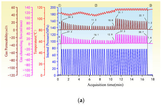
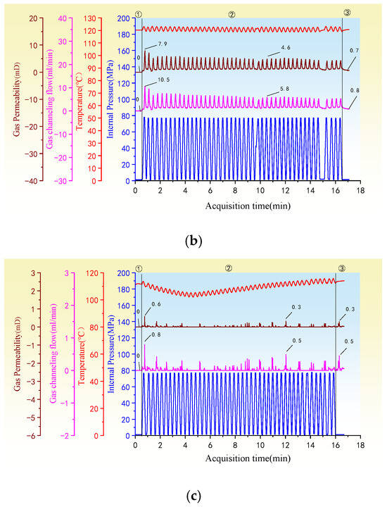
Figure 13.
Damage evaluation data of cement sheath systems under simulated fracturing conditions. (a) Formulation No. 1, (b) Formulation No. 2, (c) Formulation No. 3.

Table 12.
Permeability analysis of cement sheath.
Following cyclic loading, internal and external pressures were maintained while dye was injected into the upper end-face of the cement sheath under pressure. After 0.5 h of injection, the specimens were retrieved and fractured for observation. As shown in Figure 14a–c, the cement sheath of Formulation 1 exhibited interface debonding and matrix cracking. The cement sheath s of Formulation 2 showed cracking within the matrix. The cement sheath of Formulation 3 had only a small amount of dye at the casing–cement sheath interface, with no substantial penetration into the matrix or interface, indicating effective sealing integrity.

Figure 14.
Structural characteristics of cement sheath specimens post-fracturing. (a) Formulation No. 1, (b) Formulation No. 2, (c) Formulation No. 3.
Comparative analysis of weighted permeability and damage mechanisms under multistage fracturing conditions reveals that expansion agents help to mitigate the degradation of zonal isolation performance at cement sheath–casing interfaces caused by microannulus. Toughening agents effectively counteract the deterioration of bulk zonal isolation properties induced by tensile crack propagation. WU, Li et al. also proposed a similar idea for cement slurry modification in 2023 [22,25]. Among all tested systems, Formulation 3 demonstrates superior sealing integrity under simulated downhole operational stresses.
3.5. Field Implementation Design
Based on the findings from laboratory experiments, the incorporation of toughening agents and expansive agents into the cement slurry system significantly enhances the shear strength, tensile strength, and deformability of the set cement sheath. These additives markedly improve the sealing capacity at the cement sheath interface, enabling the cement sheath to withstand higher ultimate loads under simulated downhole operational conditions. Notably, the sealing integrity of the cement sheath was preserved even under cyclic loading. The optimized cement slurry system (Formulation 3), selected through comprehensive laboratory evaluation, has been successfully implemented in the GL block shale oil wells. This system has been applied in 121 shale oil wells, achieving a high-quality cementing interval proportion of 88.63% in horizontal sections, thereby significantly improving the overall cementing quality of production casings in the GL block.
4. Conclusions
(1) This study presents a comprehensive evaluation method for modified cement slurry systems under fracturing conditions. The cement slurry system was tested and evaluated from three aspects: ① the mechanical properties of cement stone (compressive strength, tensile strength, flexural strength, shear strength, and triaxial strength); ② mechanical properties of the cement sheath interface (bonding strength and hydraulic sealing strength); and ③ the sealing performance of the cement sheath. This multi-dimensional evaluation framework can effectively optimize and evaluate the cement slurry system applied in the field, thereby improving the cementing quality of shale oil wells.
(2) While the addition of expansive and toughening agents had minimal effects on the compressive strength, tensile strength, and interfacial bonding strength of cement matrix, they significantly enhanced other key mechanical properties. Specifically, the addition of expansive agents increased shear strength by 78.0% and flexural strength by 22.2%. The inclusion of toughening agents led to a 16.0% increase in shear strength, a 24.2% increase in flexural strength, and an improvement of over 70% in interfacial hydraulic isolation strength.
(3) Under simulated field conditions, 45 cycles of loading were conducted to com-pare the integrity of the cement sheath seal. A set of micro-expanding and toughening cement slurry system was selected based on the results. The expanding agent mitigated the adverse effects of the micro-ring on the interface seal, while the reinforcing agent reduced the damage to the overall sealing performance of the cement casing matrix caused by tensile cracking. This cement slurry system was successfully implemented in over 100 wells in the GL block of Daqing Oilfield. The on-site application results showed that the proportion of high-quality horizontal sections reached 88.63%. Further research on the long-term sealing performance of this cement slurry system will be conducted, and we will continue to monitor the on-site application of this cement sheath.
Author Contributions
Methodology, X.Z.; Validation, X.L.; Formal analysis, J.L.; Investigation, X.Y.; Resources, X.Y. and T.J.; Data curation, W.S. and T.J.; Writing—original draft, X.Z. and W.S.; Writing—review & editing, J.L. and X.W. All authors have read and agreed to the published version of the manuscript.
Funding
This research was funded by the National Natural Science Foundation of China, grant number 52274010 and and the Science and Technology Cooperation Project of the CNPC-SWPU Innovation Alliance, grant number 2020CX040000. And The APC was funded by Petroleum Engineering School, Southwest Petroleum University.
Data Availability Statement
The original contributions presented in this study are included in the article. Further inquiries can be directed to the corresponding author(s).
Conflicts of Interest
Authors Xiaoqing Zheng, Xiutian Yang, Tao Jiang and Xin Liu were employed by the company CNPC Daqing Drilling Engineering Company Limited. The remaining authors declare that the research was conducted in the absence of any commercial or financial relationships that could be construed as a potential conflict of interest.
Nomenclature
| Professional Term | abbreviation |
| sustained casing pressure | SCP |
| American Petroleum Institute | API |
| International Organization for Standardization | ISO |
| high-pressure high-temperature | HPHT |
References
- Dash, S.K.; Chakraborty, S.; Elangovan, D. A brief review of hydrogen production methods and their challenges. Energies 2023, 16, 1141. [Google Scholar] [CrossRef]
- Gajdzik, B.; Wolniak, R.; Nagaj, R.; Grebski, W.W.; Romanyshyn, T. Barriers to renewable energy source (RES) installations as determinants of energy consumption in EU countries. Energies 2023, 16, 7364. [Google Scholar] [CrossRef]
- Wu, X.; Li, Z.; Hou, Z.; Liu, J.; Huang, S.; Su, D.; Li, J.; Cao, C.; Wu, L.; Song, W. Analytical perspectives on cement sheath integrity: A comprehensive review of theoretical research. ACS Omega 2024, 9, 17741–17759. [Google Scholar] [CrossRef]
- Oyarhossein, M.; Dusseault, M.B. Wellbore Stress Changes and Microannulus Development Because of Cement Shrinkage. In Proceedings of the 49th Rock Mechanics/Geomechanics Symposium, San Francisco, CA, USA, 28 June–1 July 2015. [Google Scholar]
- Guo, S.; Bu, Y.; Yan, X. Cement Sheath Integrity under Two Different Formation Conditions in Steam Stimulation Well. In Proceedings of the International Ocean and Polar Engineering Conference, Busan, Republic of Korea, 21–26 June 2015. [Google Scholar]
- Albawi, A.; De Andrade, J.; Torsæter, M.; Opedal, N.; Stroisz, A.; Vrålstad, T. Experimental Set-Up for Testing Cement Sheath Integrity in Arctic Wells. In Proceedings of the OTC Arctic Technology Conference, Houston, TX, USA, 10–12 February 2014. [Google Scholar]
- Taleghani, A.; Wang, W. Cement Sheath Integrity During Hydraulic Fracturing; An Integrated Modeling Approach. In Proceedings of the SPE Hydraulic Fracturing Technology Conference, The Woodlands, TX, USA, 4–6 February 2014. [Google Scholar]
- Tian, Z.; Shi, L.; Qiao, L. Research of and countermeasure for wellbore integrity of shale gas horizontal well. Nat. Gas Ind. 2015, 35, 70–77. [Google Scholar]
- Xi, Y.; Li, J.; Tao, Q.; Guo, B.; Liu, G. Experimental and numerical investigations of accumulated plastic deformation in cement sheath during multistage fracturing in shale gas wells. J. Pet. Sci. Eng. 2020, 187, 106790. [Google Scholar] [CrossRef]
- Liu, K.; Gao, D.; Zeng, J.; Wang, Z. Study on Cement Sheath Integrity in Horizontal Wells During Hydraulic Fracturing Process. In Proceedings of the 52nd U.S. Rock Mechanics/Geomechanics Symposium, Seattle, WA, USA, 17–20 June 2018. [Google Scholar]
- Lu, Y.H.; Yang, S.; Jin, Y.; Chen, M.; Yang, Y.K.; Yi, Z.C.; Li, K.C. Experiments and Finite Element Simulation on Cement Sheath Failure in HPHT Well Fracturing. In Proceedings of the 50th U.S. Rock Mechanics/Geomechanics Symposium, Houston, TX, USA, 26–29 June 2016. [Google Scholar]
- Yu, G.; Xu, J.; Liu, W.; Liu, H.; Hou, X. A modified model of cement sheath stress distribution with a fixed far-field displacement boundary condition. Chem. Technol. Fuels Oils 2023, 59, 362–374. [Google Scholar] [CrossRef]
- Di Lullo, G.; Rae, P. Cements for Long Term Isolation—Design Optimization by Computer Modelling and Prediction. In Proceedings of the IADC/SPE Asia/Pacific Drilling Technology, Kuala Lumpur, Malaysia, 11–13 September 2000. [Google Scholar]
- Ravi, K.; Bosma, M.; Gastebled, O. Improve the Economics of Oil and Gas Wells by Reducing the Risk of Cement Failure. In Proceedings of the IACD/SPE Drilling Conference 2002, Dallas, TX, USA, 26–28 February 2002. [Google Scholar]
- Li, X.R.; Gu, C.W.; Ding, Z.C.; Feng, Y.C. THM coupled analysis of cement sheath integrity considering well loading history. Pet. Sci. 2023, 20, 447–459. [Google Scholar] [CrossRef]
- Lian, W.; Li, J.; Xu, D.; Lu, Z.; Ren, K.; Wang, X.; Chen, S. Sealing failure mechanism and control method for cement sheath in HPHT gas wells. Energy Rep. 2023, 9, 3593–3603. [Google Scholar] [CrossRef]
- Singh, P.; Sinha, M.P.; Lal, K.; Malhotra, S.K.; Kumar, P. Stress Modelling and Design of Elastic Cement System to Withstand Well-Bore Pressure During Hydro-Fracturing and Casing Integrity Testing. In Proceedings of the Society of Petroleum Engineers, Mumbai, India, 4–6 April 2017. [Google Scholar]
- Fan, M.; Li, J.; Liu, G. Study on the sealing integrity of cement sheath during volume fracturing of shale gas of horizontal well. Clust. Comput. 2019, 22 (Suppl. 2), 5009–5016. [Google Scholar] [CrossRef]
- Han, X.; Feng, F.; Zhang, J. Study on the whole life cycle integrity of cement interface in heavy oil thermal recovery well under circulating high temperature condition. Energy 2023, 278, 127873. [Google Scholar] [CrossRef]
- Su, D.; Li, J.; Huang, S.; Li, Z.; Wu, X. Novel Method for Characterizing the Mechanical Properties of the Cement Sheath Based on Hollow-Cylinder Specimen and Multiaxial Load Tests. SPE J. 2023, 28, 950–964. [Google Scholar] [CrossRef]
- Zhou, S.; Liu, R.; Zeng, H.; Zeng, Y.; Zhang, L.; Zhang, J.; Li, X. Mechanical characteristics of well cement under cyclic loading and its influence on the integrity of shale gas wellbores. Fuel 2019, 250, 132–143. [Google Scholar] [CrossRef]
- Wu, X.; Liu, J.; Li, Z.; Song, W.; Liu, Y.; Shi, Q.; Chen, R. Failure analysis of cement sheath mechanical integrity based on the statistical damage variable. Acs Omega 2023, 8, 2128–2142. [Google Scholar] [CrossRef]
- DZ/T 0217-2020; Reserve Estimation Specifications for Petroleum and Natural Gas. Ministry of Natural Resources of the People’s Republic of China: Beijing, China, 2020.
- SY/T 6285-2011; Methods for Evaluation of Oil and Gas Reservoirs. Industry Standard—Petroleum: Beijing, China, 2020.
- Li, J.; Liu, J.; Li, Z.; Liu, Y.; Yu, C.; Song, W.; Wu, X.; Yang, F.; Su, D. Failure analysis and countermeasures for cement sheath interface sealing integrity in shale gas wells. SPE J. 2023, 28, 2830–2844. [Google Scholar] [CrossRef]
Disclaimer/Publisher’s Note: The statements, opinions and data contained in all publications are solely those of the individual author(s) and contributor(s) and not of MDPI and/or the editor(s). MDPI and/or the editor(s) disclaim responsibility for any injury to people or property resulting from any ideas, methods, instructions or products referred to in the content. |
© 2025 by the authors. Licensee MDPI, Basel, Switzerland. This article is an open access article distributed under the terms and conditions of the Creative Commons Attribution (CC BY) license (https://creativecommons.org/licenses/by/4.0/).