1. Introduction
Geothermal energy is increasingly recognized as a key renewable energy resource with the potential to make significant contributions to global decarbonization efforts. As of 2021, global geothermal electricity generation has reached an installed capacity of 15.96 gigawatts-electric (GWe), with an average annual growth rate of 3.5% [
1]. While these advancements are notable, the growth trajectory of geothermal energy remains modest compared to other renewable energy technologies, suggesting that innovative strategies are needed to accelerate its adoption. Enhanced Geothermal Systems (EGS), which aim to expand geothermal resource utilization by engineering reservoirs in low-permeability rocks, represent a promising avenue for such advancements.
Geothermal energy comes from Earth’s heat, including primordial and radioactive sources produced by the long-term decay of isotopes such as
40K,
232Th,
235U, and
238U, the primary contributors to terrestrial heat flow over geologic timescales [
2]. Heat is transported from the inner core to the geothermal reservoirs through conduction, convection, and advection, allowing for the drilling of wells to harvest heat for electricity generation, as well as heating and cooling systems (see
Figure 1a). EGS generates electricity through a process analogous to the Rankine cycle, as illustrated in
Figure 1. In this thermodynamic system, isentropic compression (+W
in) by a pump pressurizes the cold working fluid, which is then injected into subsurface fractures. The fluid absorbs heat from the hot dry rock (HDR) reservoir through heat addition (+Q
H), followed by isentropic expansion (−W) in the turbine to produce mechanical work. The heated fluid brought to the surface will either vaporize directly or transfer heat to a secondary working fluid in binary systems, producing vapor that drives a turbine-generator set [
3]. Finally, the fluid undergoes isobaric heat rejection (−Q
L) in the condenser before the cycle repeats. Unlike conventional geothermal systems that rely on naturally permeable reservoirs, EGS utilizes engineered fracture networks to extract heat from low-permeability hot rock formations via circulation of a working fluid. The creation and maintenance of a stable fracture network is therefore critical to ensuring sustained heat extraction and long-term energy production from the Earth’s crust. A critical limitation in geothermal systems is the low to ultra-low permeability between injection and production wells, which severely restricts heat recovery. Nevertheless, a significant portion of geothermal heat can be extracted from HDR by enhancing conductivity of the fracture network between injection and production wells. This limitation can be addressed by developing enhanced or engineered geothermal systems, which are artificially created reservoirs designed to improve connectivity between the wellbore and the low-permeability geothermal formations. Within this context, the development and deployment of high-performance, thermo-chemically enhanced proppant materials specifically tailored for EGS applications could play a transformative role in improving long-term reservoir performance and fracture conductivity.
In the oil and gas industry, proppants have revolutionized hydraulic fracturing by maintaining fracture conductivity under considerable pressure and temperature conditions [
4]. However, their direct transfer to EGS applications requires careful evaluation due to the significantly different operational environments, including elevated temperatures and complex geochemical interactions in geothermal reservoirs. The thermal and chemical stability of proppants has been enhanced through innovative coating technologies, such as resin-based, polymer-based, and nanomaterial-enhanced coatings, which improve critical performance metrics like crush resistance, thermal stability, and wettability [
5,
6,
7,
8]. These enhancements can reduce the impact of common challenges such as proppant crushing, embedment, fracture conductivity loss, and flowback issues. Proppants play a central role in maintaining fracture conductivity across subsurface energy domains, ranging from shale gas and CO
2 fracturing to hydrate-bearing sediments and EGS reservoirs. Ref. [
9] showed that kaolinite proppant behavior in CO
2-rich fluids is strongly influenced by particle size, roughness, and the opposing effects of temperature and pressure on sedimentation, with CO
2 thickener adsorption and fluid microstructure playing key roles. Similarly, ref. [
10] demonstrated that fracture conductivity in hydrate-bearing sediments increases with proppant size, concentration, and hydrate saturation, but declines under higher closure pressure—directly impacting gas recovery potential.
While conventional hydrocarbon reservoirs typically operate within a temperature range of 60–120 °C (±2 °C) [
11], with unconventional reservoirs going just above 120 °C, as shown in
Table 1, geothermal systems typically exceed these thresholds. According to [
12], geothermal power generation typically requires a minimum reservoir temperature of approximately 100 °C, with moderate-temperature systems operating between 230–300 °C, and ultra-high-temperature systems exceeding 300 °C. Given the elevated thermal conditions in EGS reservoirs, there is a critical need for proppants with high thermo-chemical resistance to ensure long-term mechanical integrity and chemical stability under those subsurface environments.
Table 1 presents a comparative overview of subsurface conditions across representative unconventional oil and gas reservoirs, namely the Lower Eagle Ford Group and the Permian Basin, and two EGS sites: Utah FORGE and the Blue Mountain geothermal field. These environments differ markedly in terms of thermal, mechanical, and geochemical regimes, all of which critically influence proppant performance and long-term stability.
EGS reservoirs such as Utah FORGE and Blue Mountain are characterized by elevated formation temperatures exceeding 175 °C, significantly surpassing the operational tolerance of many conventional proppants. In particular, sand, resin-coated sands (RCS), and polymeric proppants, commonly used in oil and gas stimulation, are prone to thermal degradation under such conditions, manifesting as resin softening, fines release, and eventual structural collapse [
5,
11].
While the effective closure stresses in EGS may be comparable to those in unconventional oil and gas formations, the mechanical toughness of the host rocks, including granite, quartzite, diorite, and other crystalline lithologies, results in increased abrasive wear and potential crushing of proppants during closure. EGS environments typically expose proppants to geothermal brines with low pH and elevated salinity, conditions that significantly enhance silica leaching and destabilization, especially for sand-based proppants [
13]. Thus, in geothermal applications, it is not only mechanical stress but also temperature, fluid, and proppant chemistry that become dominant controls on long-term proppant stability.
Table 1.
Comparison of subsurface conditions across oil and gas versus EGS reservoirs, highlighting parameters critical to proppant stability (temperature, minimum horizontal stress (MHS), and lithology).
Table 1.
Comparison of subsurface conditions across oil and gas versus EGS reservoirs, highlighting parameters critical to proppant stability (temperature, minimum horizontal stress (MHS), and lithology).
| Reservoir | Permeability [mD] | Temp. [°C] | MHS [psi/ft.] | Reservoir Rock Type | References |
|---|
| Lower Eagle Ford Group | 0.001 | 125–165 | 0.35–0.85 | Carbonate-rich lithofacies | [14,15,16] |
| Permian Basin | 0.01–1000 | 27–102 | 0.5–0.79 | Dolomitized
marine carbonate | [17,18,19,20] |
| Utah FORGE | 0.021 | 175–219 | 0.61–0.74 | Granitoid and metamorphic | [21,22,23] |
| Blue Mountain geothermal field | Fault-controlled | 177–204 | N/A 1 | Metasedimentary and granitic-intrusive | [24] |
Additionally, fault-controlled flow regimes, such as those at Blue Mountain, introduce complex fracture geometries where proppants are susceptible to transport inefficiencies, stranding, or displacement, further complicating the maintenance of fracture conductivity. While surface modification techniques have improved proppant transport by reducing density and enhancing sphericity and hydrophobicity [
5], the stability of these coatings under coupled thermal, hydraulic, and chemical environments requires further investigation. These challenges necessitate the use of proppants with enhanced mechanical resilience, chemical inertness, and high thermal tolerance.
Thermal cycling is a critical factor in EGS environments, driven by repeated injection-production cycles and operational shut-ins. Unlike the relatively stable thermal regimes in conventional oil and gas reservoirs, EGS environments are characterized by abrupt and repeated temperature fluctuations that can significantly influence material performance. These cycles induce micro-cracking [
25], thermal fatigue, and interface delamination, especially in composite proppants (e.g., resin- or polymer-coated materials) where mismatches in thermal expansion coefficients between the core and coating exacerbate degradation. Over time, with the inclusion of the coupled thermo-hydro-mechanical-chemical (THMC) processes inherent in geothermal environments, such degradation compromises proppant integrity, potentially leading to loss of conductivity and reduced stimulation effectiveness.
Figure 2 expands on the fracture network shown in
Figure 1 by illustrating the coupled THMC processes that influence proppant stability within EGS environments. It highlights how thermal cycling, driven by alternating injection and production stages in geothermal operations, influences proppant behavior within the stimulated fracture system. Temperature plays a critical role in governing proppant–fluid–rock interactions, driving thermal stress, accelerating chemical reaction rates, and altering the physical and potentially mechanical properties of both the proppant materials and the surrounding geological formation.
2. Literature Review
The performance and stability of proppants under THMC conditions have been studied over the years, with significant insights gained regarding their behaviour under elevated temperature and pressure.
Ref. [
26] conducted one of the earliest investigations into the conductivity of various proppants, including sand, RCS, intermediate-strength bauxite ceramic, intermediate-strength lightweight ceramic, and high-strength bauxite ceramic, at 135 °C and 55.2 MPa over 14 days. The study revealed a drastic reduction in conductivity, with a correction factor as severe as 0.3 under extreme conditions (for sand), emphasizing the singular effect of temperature on proppant performance. Ref. [
27] assessed the stability of high and intermediate-strength proppants under temperatures ranging from 40 to 150 °C and confining pressures of 3–50 MPa over 36 days. Their findings indicated a significant permeability reduction (~50%) within the first four days, driven by chemical-mechanical interactions between the rock, fluid, and proppant. They also highlighted the pronounced impact of higher temperatures (150 °C) on permeability loss in long-term experiments.
Ref. [
28] explored sintered bauxite proppants’ chemical and thermal stability under EGS conditions with temperatures of 200–230 °C over five weeks. The study documented dissolution textures on corundum mineral faces and the deposition of amorphous silicates, aluminosilicates, and aluminum oxides/hydroxides, revealing significant geochemical alteration under such conditions. Ref. [
29] investigated the influence of self-propping, time, and closure stress on the conductivity of a 30/60 sintered bauxite proppant at ambient temperature and at 90–95 °C under a confining pressure of 13.8 MPa (2000 psi) for 1–7 days. Their results showed that although temperature effects and granite fines generation influence fracture conductivity, proppants maintained adequate performance for geothermal energy production over time. Ref. [
30] examined the geochemical interactions of bauxite-based proppants at 25 °C and 150 °C for 12–80 days under 2-bar conditions in NaCl and CaCl
2 brines. They observed that the resin coating had no significant effect on chemical stability, and high aluminum concentrations in brines indicated limited proppant stability at reservoir conditions. Ref. [
31] conducted long-term tests at 300 °F (149 °C) and 450 °F (232 °C) for 180 days. They observed that diagenetic chemical reactions at high temperatures led to geochemical scaling, permeability loss, and proppant-strength deterioration. However, coating proppants with hydrophobic styrene-maleic anhydride (SMA) materials significantly reduced the effects of these reactions, mitigating fracture diagenesis. Ref. [
32] evaluated the thermal impact on fracture conductivity evolution in granite samples using mono-layered 40/70 mesh ceramic proppants at temperatures ranging from 25 to 500 °C under 5–55 MPa confining pressures. The study found that proppant embedding depth increased with higher thermal treatment levels, which alleviated proppant crushing but exacerbated embedment. Ref. [
33] investigated the effect of a 30 MPa confining pressure and 60–90 °C temperatures on the conductivity of a proppant pack. Their findings demonstrated that proppants significantly improved hydraulic characteristics in rough fractures compared to unpropped fractures. Ref. [
34] examined the performance of resin-coated proppants under temperatures ranging from 20 to 150 °C and pressures of 5–30 MPa. The study observed that at 120 °C, the resin layer melted, causing the proppants to adhere to one another and compress flow channels, leading to reduced permeability. Ref. [
35] investigated sintered bauxite ceramic proppants at 130 °C under normal closure stresses of up to 60 MPa for 60 h. The study provided direct evidence of proppant dissolution, crushing, and embedment through stress-cycle plastic deformation measurements, hydraulic conductivity analysis, and post-test SEM imaging. Effluent chemical analysis confirmed significant geochemical interactions under these conditions.
While most of the reviewed studies have investigated the performance of proppants under coupled THMC conditions, the specific geochemical interactions between proppants and geothermal fluids remain insufficiently resolved. This study isolates thermo-chemical processes under static conditions without applied stress, to evaluate chemical reactivity independent of mechanical factors. While EGS conditions include closure stress, decoupling allows a clearer understanding of resin degradation and precipitation mechanisms. Moreover, few investigations have employed multi-scale analytical techniques to isolate and quantify chemical degradation mechanisms independent of mechanical effects, an essential step toward understanding failure pathways and advancing the development of chemically inert proppant materials for geothermal applications.
This study addresses this gap by systematically evaluating the geochemical stability and surface reactivity of commercially available proppants (coated and uncoated) under controlled geothermal conditions. The experiments focus exclusively on fluid–proppant chemical interactions over 25 days at 130 °C, incorporating thermal cycling to simulate EGS operations. The 25-day duration was chosen to capture early to intermediate stages of proppant–fluid interactions. A temperature of 130 °C was selected to evaluate proppant reactivity at the lower threshold of EGS-relevant conditions and to align with previous studies that documented notable proppant degradation and geochemical alteration within this temperature range [
21,
22,
28]. It represents a critical threshold where resin softening and ion exchange reactions begin to manifest, enabling targeted evaluation of chemical stability without the confounding effects of extreme thermal or mechanical stress. In addition, site-specific geothermal working fluids (which were later diluted as explained in the Methodology) were sourced from the Utah FORGE project to ensure that experimental conditions accurately reflected in-situ geochemical environments. Scanning Electron Microscopy-energy-dispersive X-ray spectroscopy (SEM-EDS), X-ray diffraction (XRD), and micro-computed tomography (micro-CT) techniques are used to evaluate chemical degradation processes.
This research aims to decouple chemical degradation processes from mechanical effects and to provide a clearer understanding of proppant reactivity, coating behavior, and long-term compatibility with low-temperature geothermal fluids. This article is a revised and expanded version of a paper entitled “Geochemical Interactions of Proppants with Utah FORGE Fluids: Insights from Moderate-Temperature Experiments”, which was presented at the 59th U.S. Rock Mechanics/Geomechanics Symposium (ARMA), Santa Fe, NM, USA, 8–11 June 2025 [
36].
3. Methodology
While the batch reactors were initially charged with site-specific geothermal fluids sourced from the Utah FORGE Harpoon storage tank, several vessels, particularly those containing uncrushed proppants, experienced cap failures within the first 24 h of exposure at 180 °C, likely due to pressure build-up and thermal expansion. This resulted in partial fluid loss through evaporation. To prevent further vessel damage and ensure safe experimental conditions, the tests were paused. The compromised caps were replaced with high-temperature-rated (200 °C) alternatives, and approximately 75% deionized (DI) water was added to each vessel to restore the original fluid volume.
Consequently, the working fluids in the affected reactors became a mixture of diluted FORGE geothermal fluid and deionized (DI) water. This unintended adjustment effectively created an intermediate fluid composition that bridges the two end-member systems commonly reported in previous proppant stability studies. On one end of the spectrum, several studies have used DI water exclusively as the working fluid to assess baseline proppant reactivity under simplified geochemical conditions [
26,
28,
29,
31,
35]. On the other end, researchers have tested proppants in synthetic brines formulated from DI water and specific chemical additives (e.g., NaCl, CaCl
2, NaOH, KCl, or silica) to simulate particular subsurface chemistries [
26,
28,
30,
34]. Given this context, the diluted FORGE fluid employed in this study provides a valuable intermediate case, capturing aspects of both natural reservoir water composition and controlled laboratory formulations, thereby enhancing the relevance of the results for both field and laboratory-scale geothermal applications.
Following these modifications, the remainder of the experiment was conducted at a revised temperature of 130 °C. All subsequent analyses and interpretations presented in this study reflect the impact of this altered fluid composition and adjusted temperature regime. The experimental framework, illustrated in
Figure 3, was designed to evaluate the thermo-hydro-chemical (THC) interactions between selected proppant materials (1 ultra-low density ceramic (ULD), 1 coated proppant and 2 sand proppants), both in their as-received granular (uncrushed) and mechanically milled forms (using Spex Ball Mill from SPEX Industries, Inc., Metuchen, NJ, USA) and working fluids under simulated low-temperature EGS conditions.
The investigation was conducted in three sequential stages:
Stage 1 (Pre-exposure Characterization): Baseline characterization of the proppant materials was conducted to evaluate their initial morphological, mineralogical, and elemental properties prior to fluid exposure. As shown in
Figure 3, both uncrushed and powdered proppant samples were analyzed to investigate the influence of particle size and surface area on subsequent reactivity. Uncrushed proppants were examined using SEM-EDS and micro-CT, while powdered samples were analyzed via XRD to determine mineralogical composition.
Stage 2 (Static THC Exposure Tests): Proppant–fluid static exposure experiments were conducted to simulate geochemical interactions under low-temperature geothermal conditions. In Step (i), proppant materials were mixed with working fluids and sealed in PYREX round media storage bottles equipped with high-temperature caps. In Step (ii), the bottles were placed in water-filled nest containers at ambient conditions. In Step (iii), the sealed systems were exposed to static batch reactions at 130 °C for 25 days to simulate subsurface fluid–solid interactions. Step (iv) introduced thermal cycling to replicate the injection–production fluctuations characteristic of EGS. Each 24-h cycle consisted of heating to 130 °C followed by cooling to approximately room temperature, sustained for 25 days.
Stage 3 (Post-exposure Characterization): Following the 25-day THC exposure, post-reaction analyses were conducted on the solid phases to evaluate geochemical alterations. The same suite of characterization techniques used in Stage 1 was applied.
3.1. Stage 1 and 3—X-Ray Diffraction
The mineralogical composition of powdered proppants was characterized via XRD before and after static exposure. Analyses were conducted using a Bruker D8 Advance X-ray Diffractometer equipped with a Lynxeye detector. Scans were performed over a 2
θ range of 3–80°, with a step size of 0.002° and a dwell time of 0.10 s per step. Diffraction patterns were processed and analyzed using Bruker’s AXS Diffrac.EVA software Ver 5.2.0.5 (2-25-2020) for semi-quantitative mineral phase evaluation. To quantify and identify peak changes and the emergence of new peaks, Equation (1) and a condition given in Equation (2) were used, respectively.
where,
is the intensity change at each angle
,
is the peak intensity after reaction, and
is the peak intensity before interactions.
where,
is a baseline noise threshold and
is the minimum required intensity to qualify as a new peak (commonly > counts above noise peaks).
3.2. Stage 1 and 3—Scanning Electron Microscopy-Energy-Eispersive X-Ray Spectroscopy
SEM was performed to evaluate surface and subsurface morphological features of both sand and coated proppants. Prior to imaging, samples were coated with a thin layer of iridium to enhance conductivity and minimize charging effects during high-resolution imaging. For the ultra-low-density (ULD) resin-coated proppant, analyses were conducted on both the outer resin layer and the inner core, while for sand proppants, only the external surfaces were examined. Imaging was carried out using a ThermoFisher FEI Scios2 Dual Beam Scanning Electron Microscope in both secondary electron (SE) and backscattered electron (BSE) modes to capture topographical and compositional contrast, respectively. Elemental analyses were performed using a Bruker EDS X-ray microanalysis system integrated with the SEM. EDS was used to conduct both area scans and point analyses. These analyses enabled the identification of bulk compositional trends as well as localized geochemical alterations on selected regions of interest (ROIs), providing insight into proppant degradation, elemental leaching, and surface modification following exposure to diluted geothermal fluids. For each proppant type, elemental mapping was performed across at least three rectangular regions that covered the most representative surface areas. The elemental data from these regions were then averaged to enable a reliable comparison of surface composition before and after reaction.
3.3. Stage 1 and 3—Micro-CT Analysis
Micro-computed tomography (micro-CT) was employed in this study to non-destructively evaluate the internal structural evolution of proppant materials before and after exposure to geothermal fluids under thermal cycling. While traditional assessments of proppants focus on mechanical properties such as crush resistance or sphericity, the internal pore network and how it evolves due to fluid–solid interactions play a critical role in long-term proppant stability. In EGS, where proppants are exposed to prolonged chemical reactivity under high temperatures, internal pore dissolution can weaken the grain structure, increasing the likelihood of crushing and fines generation. Conversely, pore-filling precipitation may clog internal voids, alter grain density, especially for coated proppants affects mainly the proppant coating structure, potentially affecting the pack’s permeability. These microstructural changes can directly influence fracture conductivity and long-term reservoir performance. Therefore, micro-CT provides a high-resolution, three-dimensional means of quantifying both intra- and intergranular porosity, enabling detection of subtle internal degradation pathways that are not apparent from surface observations alone. Micro-CT imaging was performed using a ZEISS Versa 410 X-ray microscope. The scanning parameters are summarized in
Table 2. Samples were placed in 3 cm tall plastic straws, with the top and bottom openings secured with clay, and mounted on an aluminum holder for scanning. The 1601 projections were acquired for a full 360° rotation. These projections were reconstructed using XRM Reconstructor software (Ver 16.1.13038) to generate 2D images.
The CT images were processed and analyzed using Dragonfly 3D visualization and analysis software (version 2022.2) by Object Research Systems. The images were imported as TIFF files and denoised with a gaussian filter with a kernel size of 5 and a standard deviation of 2.0. A cuboidal subvolume with a pixel size of 2.67 µm (H = 1.45 mm, W = 1.97 mm, and D = 2.047 mm) was extracted from the centre of each image stack to perform the segmentation and constituent data analysis. In all scans, regions of air and solid materials were clearly differentiated based on grayscale contrast, with void spaces and solid phases having different colour shades.
3.4. Stage 2—Batch Reactor Experiments
In Stage 2, as received and powdered proppants were subjected to static batch reactions. The experiments incorporated daily thermal cycling to emulate subsurface temperature fluctuations associated with cyclic injection–production operations typical of EGS. This setup was designed to simulate the coupled THC processes that govern in situ proppant performance. Although mechanical stresses were not applied in this study, the experimental framework was designed to capture the dominant chemical interactions, including resin degradation, dissolution–precipitation processes, and elemental leaching at the proppant–fluid interface. The proppant materials tested include,
White Sand (20/40 mesh) and Brown Sand (40/70 mesh): Representative of standard silica-based proppants widely used in hydraulic fracturing due to their cost-effectiveness and abundant availability.
RCS (20/40 mesh): Selected for its enhanced resistance to pronounced degradation compared to sand proppants.
ULD Ceramic Proppant (40/70 mesh): This ultra-low-density ceramic proppant was engineered primarily to enhance production rates and estimated ultimate recovery (EUR) in slickwater fracturing operations. Its design incorporates significant intragranular porosity, yielding an apparent density of approximately 2.0 g/cm3, substantially lower than that of conventional quartz sand (~2.65 g/cm3) and standard low-density ceramic proppants. This reduced density improves proppant transport and suspension in low-viscosity carrier fluids. It is important to note that, although ceramic-based, this material is intentionally not a fully sintered ceramic, distinguishing it from conventional low, intermediate, and high-strength ceramic proppants commonly used in oil and gas applications.
The working geothermal fluid was sourced from the Harpoon storage tank, which contains fluids to be injected into the Utah FORGE 16A(78)-32 injection well. The fluid’s initial composition (before adding DI), including major cations, anions, and trace elements, is detailed in
Table 3. This site-specific fluid was chosen to accurately represent the in-situ geochemical environment of the Utah FORGE reservoir, thereby ensuring that laboratory conditions closely mimic the reactive interactions between proppants and reservoir fluids under low-temperature geothermal settings.
Following static exposure, all reacted proppant samples were thoroughly rinsed with deionized water to remove residual fluid and loosely bound surface precipitates, then oven-dried at 40 °C for 24 h. The dried samples were subsequently subjected to a comprehensive suite of post-reaction characterization techniques as part of Stage 3, aimed at evaluating morphological, mineralogical, and elemental changes resulting from thermo-hydro-chemical interactions.
4. Results
4.1. Visual Changes in Fluid Appearance and Observable Proppant Surface Changes
Following a 25-day static interaction at 130 °C between the tested uncrushed proppants and the working fluid, notable physical and chemical changes were observed in both the solid and liquid phases. After the reaction, fluids were separated from the proppant materials using syringes fitted with 0.2 μm PTFE membrane filters and collected in transparent containers to facilitate qualitative visual assessment of fluid clarity and color changes. Pre- and post-reaction photographs were taken to document variations in fluid appearance.
Figure 4a shows the visual differences in fluid clarity after exposure to the various proppant types. Fluids recovered from interactions with uncoated sand proppants (white and brown) appeared slightly cloudy, suggesting moderate particulate suspension. In contrast, fluids in contact with resin-coated proppants (RCS and ULD ceramic) displayed more pronounced discoloration, developing a distinct brown hue, likely due to resin breakdown or leaching of reaction byproducts.
Figure 4b presents comparative pre- and post-exposure images of proppant granules, revealing key morphological transformations:
ULD ceramic proppants showed a noticeable shift from a bright yellow to a light brown coloration post-exposure. Isolated grain agglomerations were observed, likely due to thermally activated softening or partial reconstitution of the coating material.
RCS proppants exhibited the most significant changes, with color darkening from light brown to dark brown. Extensive resin redistribution and apparent thermal activation were noted, leading to localized grain clustering. A white residue, possibly indicative of precipitated reaction products, was identified on the clustered particles.
White and brown sand proppants exhibited no significant morphological degradation or color change following exposure, with only minor surface lightening observed during visual inspection.
4.2. X-Ray Diffraction Analysis
Pre- and post-reaction XRD assessment focused on identifying the emergence of new diffraction peaks, shifts in peak positions, and changes in relative peak intensities, all indicative of possible phase transformations, dissolution–precipitation dynamics, or structural modifications of the proppant powder material. While these metrics provide useful insight into mineralogical evolution, it is recognized that reaction-induced products may include amorphous or poorly crystalline phases, which cannot be reliably detected by XRD, particularly when present in quantities below the ~2 wt.% detection limit.
Given the limitations, no specific mineral phases were assigned to newly observed peaks in order to avoid speculative interpretations. Instead, proppant reactivity was qualitatively assessed based on observable peak modifications, including the appearance of new reflections, peak intensity fluctuations, and lattice shifts, which collectively signal geochemical or structural changes resulting from the static interaction with diluted geothermal fluids.
Figure 5 and
Figure 6 present the XRD diffractograms of coated and sand-based proppant powders before and after the experiment.
Figure 5a presents the XRD diffractograms for the ULD ceramic proppant, which is primarily composed of mullite along with broad amorphous peaks likely associated with binders, resins, dispersants, and foaming agents. Notable reductions in peak intensities were observed at 12.2°, 16.4°, and 21.6° 2
θ, corresponding to known epoxy resin signatures, as indicated by the comparison between pre- and post-reaction spectra (ULD before vs. ULD after). Additional major declines were noted at 26.3° and 35.2° 2
θ (refer to ∆ peak), suggesting both resin degradation and possible breakdown of binder components. The difference in peak intensity was also quantified and is represented by the purple graph (∆ Peak) in
Figure 5a, highlighting regions of structural and chemical transformation. To isolate newly formed peaks, the following threshold condition was applied: “If Intensity
before < 1 and Intensity
after > 50, then classify as a ‘New Peak’.” Following exposure, new major peaks (New peak) emerged at 29.0°, 31.7°, and 45.4° 2
θ, indicating the formation of secondary mineral phases likely due to geochemical reactions between the ceramic matrix and geothermal fluid.
Collectively, the disappearance of primary peaks and emergence of new reflections confirms significant thermo-chemical reactivity of the ULD ceramic proppant under simulated low-temperature EGS conditions.
Figure 5b presents XRD data for the RCS proppant, which was mainly quartz. Compared to ULD ceramic, the RCS proppant exhibited more subtle changes in diffractograms. While a minor reduction in peak intensities occurred between 26° and 80° 2
θ, only a few low-intensity new peaks appeared, most notably at 31.7° 2
θ. A more stringent threshold, “If Intensity
before < 1 and Intensity
after > 350, then classify as ‘New Peak’,” was applied to coated and natural sand-based proppants to eliminate noise and isolate relevant diffraction signals.
Figure 6a,b show the diffractograms for white and brown sand proppants, respectively. Both materials exhibited the emergence of new major peaks at 31.7° and 45.0° 2
θ, consistent with the secondary phase development observed in the RCS proppants.
The newly observed crystalline phases likely correspond to the precipitation of secondary salts, aluminosilicates, or metal silicates, driven by ongoing dissolution–precipitation processes and ion exchange reactions with the geothermal fluid. The RCS and white sand proppants both predominantly composed of quartz, exhibited comparable reactivity, as evidenced by similar peak shifts and the emergence of new reflections at consistent 2θ positions. In contrast, the brown sand proppant, which initially contained calcium aluminum silicate phases, exhibited fewer new diffraction peaks, indicating reduced formation of secondary crystalline phases for powdered liquid-solid interactions.
Although peak attenuation was less pronounced in the sand proppants compared to the ULD ceramic material, the presence of new reflections and complementary elemental data points to active surface-level geochemical interactions, particularly via precipitation of fluid-borne species onto the proppant surfaces.
4.3. SEM-EDS Analysis
Figure 7 presents representative SEM images of proppant materials before and after static fluid exposure: (a) ULD ceramic proppant, (b) resin-coated sand (RCS), (c) white sand, and (d) brown sand. Prior to exposure, the ULD ceramic proppant exhibited a smooth, dark surface characteristic of a continuous resin coating. Post-exposure, notable surface degradation was observed, including whitening and the development of localized surface disruptions. Regions of clustering indicated by arrows revealed elevated concentrations of silicon and aluminum in EDS scans (elements associated with the ceramic core), suggesting rupture of the coating and exposure of the underlying structure. The RCS proppant (
Figure 7b) initially displayed a uniform resin coating, which, after exposure, showed evidence of delamination and scaling. Scale-like textures and small surface voids were apparent, accompanied by whitening and particle clustering. SEM-EDS analysis of the agglomerated regions (shown by arrows) indicated enrichment in carbon, chlorine, and calcium, consistent with resin softening, migration, and ion precipitation from the geothermal fluid. In the white sand proppant (
Figure 7c), only minor morphological changes were visible. However, bright surface deposit features emerged after fluid exposure, possibly indicating incipient surface precipitation. The brown sand proppant (
Figure 7d) displayed more visible alteration than the white sand. SEM images revealed the formation of surface deposits or secondary mineral phases, particularly along grain boundaries, along with similar white features as seen in the white sand. These are interpreted as precipitation products resulting from dissolution–precipitation processes at the solid–fluid interface.
SEM observations collectively highlight distinct chemical and morphological responses among the tested proppants. The coated proppants (ULD and RCS) exhibited significant surface degradation, further evidenced in
Figure 8. In the ULD proppant (
Figure 8a), white, extrusion-like deposits were observed on the surface. SEM-EDS point analysis of these features revealed a composition primarily of oxygen (61.55%), calcium (20.29%), and carbon (16.67%), along with minor elemental constituents, suggesting precipitation of fluid-derived species and resin degradation.
Figure 8b shows the RCS proppant after exposure, with an exposed quartz-rich substrate and an unevenly redistributed coating layer, indicative of thermal softening and partial resin delamination.
Although the uncoated sand proppants appeared morphologically stable, they may have experienced chemical alterations that are not readily detectable by SEM imaging alone. Despite their intact appearance, these materials may exhibit higher chemical reactivity than visually suggested. In contrast, while the coated proppants showed clear physical degradation, they may offer greater resistance to fluid-induced chemical alteration due to the protective function of their resin or ceramic coatings. To further investigate internal compositional characteristics,
Figure 9a,b present SEM images of mechanically fractured, unreacted ULD ceramic and RCS proppants, respectively. These images were obtained to examine the baseline elemental distribution between the outer coating layers and the internal core structures prior to fluid exposure. Internal EDS analysis was conducted only for the ULD ceramic, as the RCS proppant’s surface alterations closely resembled those of uncoated sand, suggesting that similar geochemical interactions likely occurred within the core, making additional internal characterization unnecessary. Two key factors influencing proppant integrity were identified from the SEM analysis of fractured proppants:
Fine Particle Generation: In conventional hydraulic fracturing, once fluid injection ceases, the reservoir transitions to closure stress conditions normally dominated by the minimum horizontal principal stress (Sh
min). Under such metamorphic or igneous formation-induced stress, proppant crushing may occur, resulting in the formation of fines, which can significantly impair fracture conductivity and clog pore throats within the formation. As shown in
Figure 9a, the ULD ceramic proppant exhibits less fine generation, indicating strong resistance to internal fragmentation. In contrast, the RCS proppant,
Figure 9b, displays substantial fine particle generation highlighted by the white circle, suggesting reduced mechanical robustness and a greater susceptibility to degradation under confinement.
Coating Thickness: The ULD proppant is characterized by a thicker resin coating compared to the thinner coating observed on the RCS proppant. In the context of geothermal environments, where high temperatures and chemically aggressive fluids can degrade coating integrity, a thicker coating may offer enhanced chemical shielding, thereby extending proppant durability. This increased barrier may also help preserve proppant geometry, reduce the rate of elemental leaching, and ultimately contribute to maintaining fracture conductivity over time.
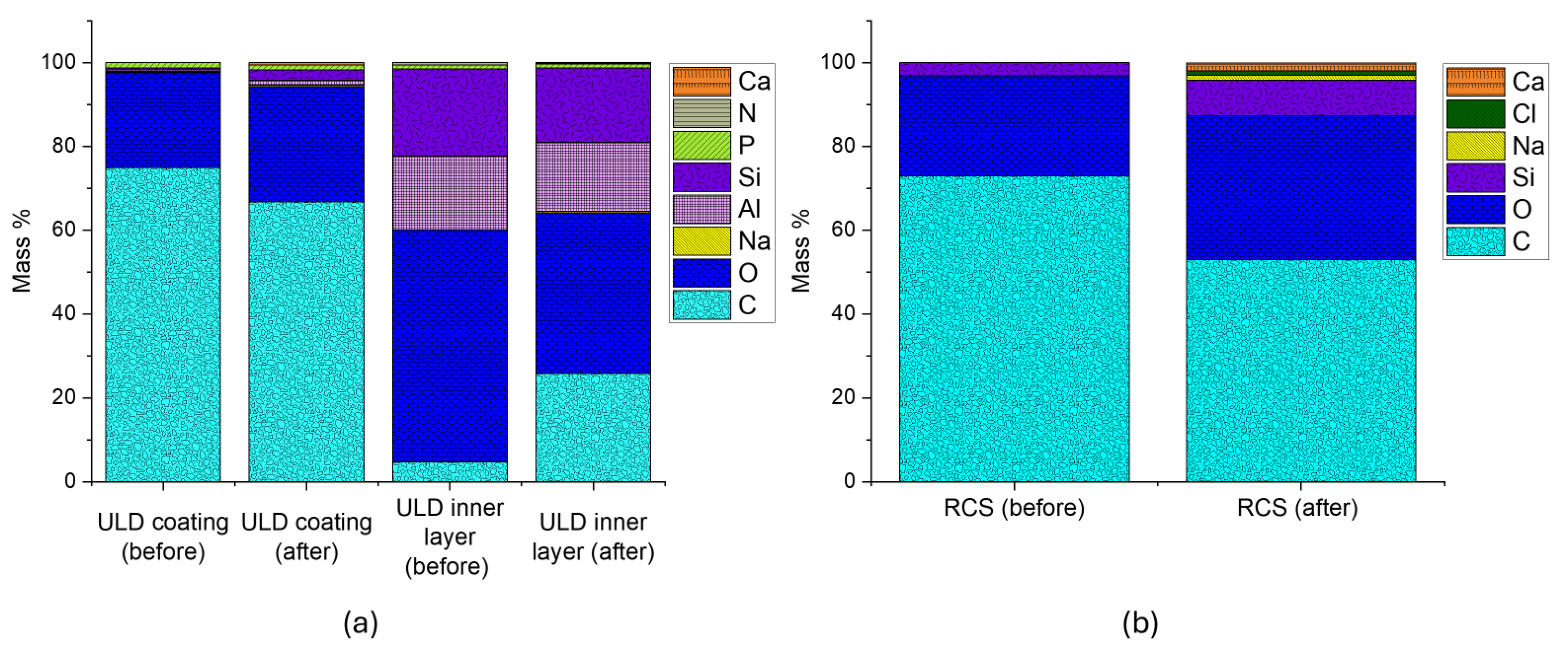
Figure 10a,b presents EDS data for the ULD ceramic proppant and RCS proppant, respectively. For the ULD ceramic proppant, the pre-reaction resin coating was primarily composed of Carbon (C) (74.97%) and Oxygen (O) (22.69%), with trace amounts of Sodium (Na) (0.14%), Aluminum (Al) (0.49%), Silica (Si) (0.51%), and Phosphorus (P) (1.21%). Post-exposure analysis revealed a decrease in C content to 66.80%, indicating thermal and chemical degradation of the organic resin. Concurrently, Calcium (Ca) emerged in the elemental profile, and concentrations of Na (0.29%), Al (1.22%), Si (2.54%), and P (1.15%) increased, suggesting partial erosion of the coating and exposure of the underlying ceramic matrix.
Analysis of the inner core of the ULD proppant revealed it was originally dominated by Si (20.86%), Al (17.54%), and O (55.45%). Following liquid-solid interactions, both Si (17.75%) and Al (16.56%) decreased, while C increased, implying resin softening and diffusion into the internal structure. This carbon infiltration may reduce intraparticle porosity, potentially compromising the initial structural integrity of the proppant. The appearance of additional elements in the post-reaction spectrum further supports chemical exchange between the degraded coating and fluid components.
In
Figure 10b, the RCS proppant exhibited a substantial decrease in surface C concentration, dropping from 72.98% to 53.05% following diluted geothermal fluid exposure. This decline indicates significant resin degradation, consistent with SEM observations. Simultaneously, a 171% increase in Si content was observed, indicating the exposure of the silica-based core material as the resin layer deteriorated. Post-reaction spectra also revealed the emergence of new elemental species, including Na, chlorine (Cl), and Ca elements commonly associated with precipitation reactions driven by ion exchange between the resin matrix and ionic constituents of the Utah FORGE geothermal fluid (
Table 3). Compared to the ULD proppant, the RCS proppant displayed a higher overall concentration of secondary species.
Figure 11a,b presents EDS results for white and brown sand proppants, respectively, extending the elemental analysis to uncoated materials.
Although SEM imaging (
Figure 7) showed minimal morphological degradation in both sand proppants, EDS analysis revealed the presence of new elemental species on their surfaces post-exposure, indicating active surface-level geochemical interactions. The surface contribution of newly formed phases was estimated at 0.5% for ULD ceramic, 4.1% for RCS, 7.1% for white sand, and 15.2% for brown sand, highlighting increasing reactivity from coated to uncoated proppants.
Notably, both proppants exhibited reductions in Si content, 10% for white sand and 27.53% for brown sand. In addition, magnesium (Mg), Na, and Cl, major constituents of the Utah FORGE geothermal fluid, were detected on the proppant surfaces post-reaction. These findings point to ion exchange processes and secondary mineral precipitation occurring at the solid–fluid interface.
4.4. Micro-CT Analysis
To evaluate microstructural evolution, high-resolution micro-CT imaging was used to quantify both intra- and intergranular porosity in proppant samples before and after the THC static experiment. Changes in intragranular porosity were interpreted as indicators of internal reactivity:
Variations in intergranular (interparticle) porosity reflect morphological changes influenced by particle sphericity, roundness, and potential coating deformation, often resulting from precipitation-deposition reactions. An increase in intergranular porosity for coated proppants may indicate resin redistribution or particle agglomeration, leading to reduced packing efficiency. Conversely, if no fluid–solid interactions occur, intergranular porosity should remain largely unchanged.
Image segmentation was performed using the Otsu thresholding algorithm.
Figure 12a,b shows the segmentation of proppant and air space, respectively, using the Otsu method. Closed pores within the proppants (intragranular pores) were isolated by removing the external air space from the region of interest through the “process island, remove by largest” process, as determined by the 6-connected method (
Figure 12c). The segmented intragranular pores were then subtracted from the air space (
Figure 12b) to isolate the external air space (
Figure 12d).
Figure 12e displays the segmented constituents in proppant samples. This multistep segmentation approach was applied to all samples to separate pores and proppants. Quantification was conducted only on the isolated internal pores and the external air space, both before and after the exposure to working fluids, to determine the compositional changes in the proppants.
To quantitatively assess microstructural changes, intragranular porosity was calculated for each proppant type.
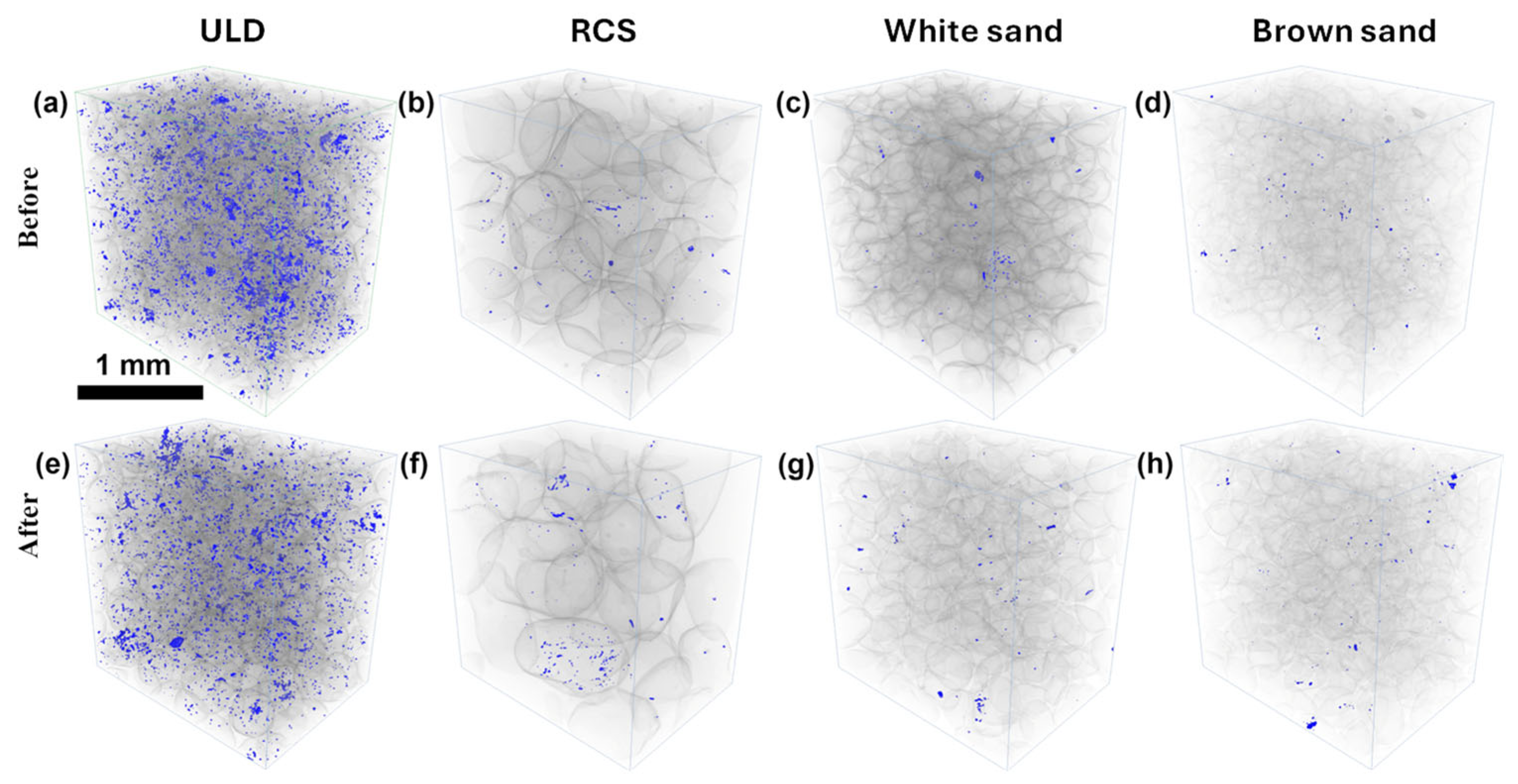
Figure 13 presents pore space segmentation, illustrating the distinction between solid proppant grains while highlighting internal proppant void spaces for all tested materials.
The corresponding porosity values, measured before and after fluid exposure, are reported in
Table 4, as determined by multi-ROI analysis, providing insight into changes in proppant packing structure, grain morphology, and resin redistribution effects.
The ULD ceramic proppant exhibited the most notable reduction in both intra- and intergranular porosity, with a 30.4% decrease in intra pore volume and a 4.8% decrease in inter pore space. This pattern suggests dominant pore-filling deposition processes, likely due to resin redistribution and secondary mineral precipitation, consistent with observations from SEM-EDS.
In contrast, the RCS proppant exhibited a substantial increase in intergranular porosity (+17.2%) while maintaining constant intragranular porosity, indicating notable resin softening and redistribution that led to grain agglomeration and reduced packing efficiency. These changes are clearly illustrated in
Figure 14, which highlights alterations in packing structure driven by resin migration. This interpretation is further supported by SEM observations (
Figure 7b) showing evidence of coating degradation and localized particle clustering.
White and brown sand proppants showed minimal changes in intragranular porosity, as expected for monolithic quartz grains. However, increases in intergranular porosity (+7.6% and +4.2%, respectively) suggest that surface-level chemical interactions are involved. White and brown sand proppants showed negligible variation in intragranular porosity, with values remaining close to 0.01% throughout. While the brown sand exhibited a 66.7% relative increase in intra-porosity, the absolute change (from 0.003% to 0.005%) is extremely small, thus not necessarily indicative of meaningful internal structural alteration.
5. Discussion
A notable limitation of this study was the failure of some reactor caps during the initial 24 h at 180 °C, which resulted in fluid loss. This was remedied by resealing the vessels and replenishing them with a 75% DI water and 25% FORGE fluid mixture, leading to a dilution of the original geothermal brine composition. Consequently, the experimental temperature was lowered and maintained at 130 °C. Although this deviated from the original design, the revised regime remains representative of low- to moderate-temperature Enhanced Geothermal System (EGS) conditions. While the reaction kinetics at 130 °C are slower, the fundamental degradation pathways such as surface precipitation, ion exchange, and internal pore modification are still expected to occur and were clearly identified in SEM–EDS, XRD, and micro-CT analyses. However, extrapolation to in-situ reservoir behavior must consider that dissolution–precipitation reactions scale nonlinearly with both temperature and ionic strength. The dilution likely reduced brine reactivity, moderating precipitation rates and possibly slowing certain mineral transformation processes. As a result, the chemical interpretations, particularly regarding ion exchange and secondary mineral growth, should be considered semi-quantitative. To improve accuracy in future studies, we recommend the use of pressure-rated reactors capable of maintaining high temperature and undiluted brine conditions to better simulate reservoir-scale behavior.
The findings of this study demonstrate that chemical degradation is a critical mechanism influencing proppant stability, particularly during prolonged exposure to geothermal fluids subjected to repeated thermal cycling. Unlike previous studies that primarily assessed mechanical behavior, such as proppant crushing, embedment, or conductivity loss under closure stress, this work isolates static thermo-hydro-chemical (THC) effects, thereby providing a more precise evaluation of fluid–proppant chemical compatibility.
Significant internal and surface changes were observed in the ultra-low-density (ULD) ceramic proppant, including a 30.4% reduction in intragranular porosity and extensive transformations in XRD peak profiles. These changes are consistent with the resin and binder degradation reported in prior studies [
30,
34], where elevated temperatures (above 120 °C) triggered resin melting, blistering, and proppant adhesion. The emergence of new crystalline peaks in ULD and quartz-based sand proppants further supports the occurrence of mineral precipitation and silica transformation, corroborating earlier observations of dissolution–precipitation cycles and high-temperature diagenetic reactions in geothermal systems [
28,
31].
The RCS proppant exhibited limited internal porosity change, yet pronounced intergranular porosity increase (+17.2%) due to resin softening and redistribution. SEM-EDS revealed carbon-, chlorine-, and calcium-enriched regions within agglomerated grains, suggesting resin melting and ion precipitation. These findings are consistent with resin layer liquefaction effects at >120 °C, as reported by [
34], where coating degradation led to grain clustering and potential flow restriction. Such resin reflow and precipitation-driven agglomeration may compromise proppant pack uniformity, potentially reducing fracture conductivity over time, particularly under low-viscosity fluid conditions typical of EGS reservoirs.
In contrast, the uncoated white and brown sand proppants, composed primarily of quartz, exhibited minimal morphological change via SEM, in line with previous findings suggesting quartz-based proppants are chemically stable under geothermal conditions [
38]. However, micro-CT analysis revealed increased intergranular porosity in both (7.6% for white sand and 4.2% for brown sand), and EDS spectra identified surface deposition of Na, Mg, and Cl. This suggests localized reactivity, particularly at grain edges and microfractures, even in otherwise inert silica-rich proppants. Surface-phase contributions followed the order: 0.5% (ULD), 4.1% (RCS), 7.1% (white sand), and 15.2% (brown sand), indicating that proppant reactivity increases from coated to uncoated materials. These trends align with [
13], which documented enhanced silica leaching and instability in sand-based proppants under geothermal conditions.
In this study, we investigated several degradation pathways, chemical, morphological, and mineralogical, that can ultimately compromise proppant integrity under geothermal conditions. To meaningfully compare materials and assess their relative tolerance to low-temperature EGS environments, it is essential to limit comparisons to materials with similar structural and compositional properties, as comparing coated and uncoated proppants would be inappropriate due to their fundamentally different degradation mechanisms. We encourage future studies to adopt a structured approach, such as multi-criteria decision analysis (MCDA), using methods like the Analytic Hierarchy Process (AHP), to guide proppant selection based on both degradation indicators and cost. For illustrative purposes, we compared two coated proppants; ULD Ceramic and resin-coated sand (RCS) across six criteria: fine generation (from SEM,
Figure 9), intragranular porosity change (
Table 4), surface precipitation area (
Figure 10), carbon content loss (from SEM–EDS), number of new XRD peaks (
Figure 5), and market price. Assuming cost ranges of
$350–
$400 per ton for ULD Ceramic and
$50–
$200 per ton for RCS, the AHP pairwise matrix to emphasize the dominant importance of minimizing fines and structural degradation while accounting for price as a practical constraint was estimated. The resulting criterion weights were: fine generation (0.520), intragranular porosity change (0.190), surface precipitation area (0.080), carbon content loss (0.060), XRD peak changes (0.050), and price (0.100). After normalization using experimental data and assumed pricing, ULD Ceramic achieved a composite AHP score of 0.880, compared to 0.410 for RCS. This example illustrates how future studies can incorporate cost, degradation metrics, and performance priorities into a unified framework, which can be further expanded to include mechanical performance under fully coupled THMC conditions.
This study advances the understanding of proppant degradation mechanisms in geothermal systems by isolating chemical effects from mechanical loading. The findings indicate that chemical degradation alone, manifested through coating redistribution, ion exchange, internal pore modification, and secondary mineral precipitation, has the potential to significantly compromise proppant integrity. These microstructural changes may directly impact long-term fracture conductivity and the overall sustainability of EGS reservoirs. To translate these laboratory-scale observations to field-scale performance, future work should incorporate flow-through and mechanical crushing tests. Such experiments are essential for quantifying how mineral precipitation and surface alteration influence proppant strength, pack permeability, and hydraulic conductivity under realistic subsurface conditions. Additionally, proppant behavior should be assessed under fully coupled THMC stresses. For example, the application of confining stress may expose further degradation mechanisms, such as enhanced fines generation in sand proppants, which can severely reduce fracture conductivity through pore throat blockage and increase geochemical reactivity due to expanded reactive surface area. Future research should therefore prioritize dynamic flow-through experiments under controlled stress conditions to better simulate the complex, high-temperature environment of geothermal reservoirs and comprehensively evaluate proppant durability. Additionally, future studies should incorporate quantitative fluid analyses such as Inductively Coupled Plasma Mass Spectrometry (ICP-MS) or Inductively Coupled Plasma Optical Emission Spectroscopy (ICP-OES) to more accurately constrain precipitation and dissolution processes, support the development of chemical reaction equations, and enable more robust geochemical modeling and interpretation of fluid–solid interaction pathways.
6. Conclusions
This study systematically evaluated the geochemical reactivity of four commercially available proppants, ultra-low-density (ULD) ceramic, resin-coated sand (RCS), white sand, and brown sand with diluted Utah FORGE working fluids under controlled Enhanced Geothermal System (EGS) conditions at 130 °C with thermal cycling over a 25-day period. Using a multi-modal analytical approach (XRD, SEM-EDS, and micro-CT), the research decoupled chemical degradation from mechanical effects to isolate fluid–proppant interactions that occur in low-temperature geothermal environments.
The results demonstrated that proppant degradation is governed not only by temperature and pressure, as shown in prior studies, but also by fluid chemistry and material-specific composition. The ULD ceramic proppant exhibited significant internal pore filling (−30.4%) and secondary mineral precipitation. RCS proppants showed substantial surface-level resin redistribution, leading to a 17.2% increase in intergranular porosity and exhibited a substantial decrease in surface C concentration, dropping from 72.98% to 53.05%. Uncoated sand proppants, despite minimal visual morphological change, exhibited measurable increases in porosity and surface precipitation, highlighting their interactions with geothermal fluids.
These findings reinforce the importance of fluid–proppant chemical compatibility in the long-term viability of EGS systems. The study also revealed that coating thickness, elemental composition, and proppant morphology collectively influence degradation mechanisms, such as resin leaching, grain clustering, and ion exchange reactions.
By decoupling chemical and mechanical degradation and introducing a comprehensive fluid–proppant framework, this work advances the mechanistic understanding of proppant behavior in chemically evolving geothermal reservoirs. These insights support the need for continued development of high-temperature-stable proppants and coatings, and for integrating realistic reservoir fluid pathways, including evolved rock–fluid interactions, into future testing protocols.


