Abstract
Swirl spray combustion has attracted significant attention due to its common usage in gas turbines. However, the high pressure in many practical applications remains a major obstacle to the deep understanding of flame stability and pollutant formation. To address this concern, this study investigated a swirl spray flame fueled with n-decane at elevated pressure. Planar laser-induced fluorescence (PLIF) of OH and polycyclic aromatic hydrocarbons (PAHs) were used simultaneously, enabling the distinction of the locations of OH, PAHs, and mixtures of them, providing detailed information on flame structure and evolution of PAHs. The effects of swirl number and ambient pressure on reaction zone characteristics and PAHs’ formation were studied, with the swirl number ranging from 0.30 to 1.18 and the pressure ranging from 1 to 3 bar. The data suggest that the swirl number changes the flame structure from V-shaped to crown-shaped, as observed at both atmospheric and elevated pressures. Additionally, varying swirl numbers lead to the initiation of flame divergence at distinct pressure levels. Moreover, PAHs of different molecular sizes exhibit significant overlap, with larger PAHs able to further extend downstream. The relative concentration of PAH increased with pressure, and the promoting effect of pressure on producing larger PAHs was significant.
1. Introduction
Modern combustors, such as aero-engines and gas turbines, are required to achieve higher combustion efficiency, lower pollution emissions, and a wider operating range (turn down ratio) and operate under high temperature and pressure conditions to increase thermodynamic efficiency. Swirl is a common feature of many practical combustors, which can enhance flame stabilization and minimize pollutant formation by inducing a recirculation region to improve the evaporation rate and fuel-oxidizer mixing.
Swirl flames have been extensively studied, often employing optical diagnostics that enable in situ and non-intrusive measurements. The structure of swirling flames is known to be influenced by various factors including inlet fuel/air temperature [1,2], fuel–air equivalence ratio [3,4], burner geometry [5,6], and combustor pressure [7,8]. Boxx et al. [9] performed 3 kHz particle image velocimetry (PIV) and OH planar laser-induced fluorescence (PLIF) measurements of flame dynamics in a lean, partially premixed swirl-stabilized CH4 flame at elevated pressure up to 5 bar. A similar study has also been conducted by Chterev and Boxx [10] for H2-enriched C2H4 lean swirl-stabilized flames at 5 bar to study heat release distribution, combustion instability, and flow dynamics. Subsequently, W. Agostinelli et al. [11] used large eddy simulations (LES) to further analyze the combustion dynamics of the flame described in [10]. Their results showed that both H2 addition and elevated pressure modified the flame shape, as flame height was reduced and became more compact. In addition, pressure altered the characteristic time scales of the turbulent reactive flow due to the increase in Reynolds and Damköhler numbers, along with a decrease in laminar flame speed, thermal flame thickness, and chemical time scale.
While the aforementioned studies mainly focus on gas-phase combustion, the phenomena present in aero-engines where swirl-stabilized spray combustion is prevalent are not fully captured [12]. Cavaliere et al. [13] compared flame structures and relative blow-off behaviors of swirling premixed and non-premixed methane and heptane swirl spray flames using OH* chemiluminescence and OH-PLIF. The results indicated that the structure of spray flame differed from that of methane flames and a reduced probability of local extinction was noticed. The combustion characteristics of swirl spray flames with various liquid fuels such as rapeseed methyl esters, Jet A-1, palm biodiesel/methyl esters (PME), acetone-butanol-ethanol (ABE), and glycerol were examined by Chong and Kumar et al. [14,15,16,17]. However, their work was conducted under atmospheric pressure conditions, which significantly differ from the actual operating environments of aero-engines that typically run under pressurized conditions. Extra effort is required to fulfill experimental measurement under high-pressure conditions. Recently, Slabaugh et al. [18] conducted experiments on a piloted, partially premixed, liquid-fueled swirl burner at 1 MPa. They performed 100 kHz PIV measurements to analyze the influence of combustion instability on the interaction between the flow and combustion. A novel procedure for separating OH/fuel-PLIF signal in Jet-A swirl spray flame up to 5 bar was proposed by Chterev et al. [19], which was helpful for quantifying statistics about the relative locations of fuel, OH, and a mixture of fuel and OH. To enhance combustion efficiency and reduce pollutants, Malbois and Legros et al. [20,21,22] proceeded with a series of experiments utilizing various laser diagnostics and LES within the HERON (high-pressure facility for aero-engines combustion) combustion facility fed with liquid kerosene. The distribution of droplets, flame structure, and OH/kerosene/NO PLIF were studied under pressure conditions ranging from 0.4 to 1.8 MPa. The results showed that most NO-PLIF signals distributed in the inner recirculation zone (IRZ), and the mole fraction of NO decreased with elevated pressure. Nevertheless, studies on swirl-stabilized spray flames remain limited owing to system complexities. In addition, considering the pivotal role of swirl intensity in flame dynamics, comprehensive understanding of flame behavior under varied swirl conditions is indispensable.
Furthermore, most studies of spray swirl-stabilized flames only focus on flame structures under high-pressure conditions. Given climate change and stringent emission regulations, a greater demand for understanding the soot formation mechanisms was posed, especially for systems containing hydrocarbons [23,24], e-fuels [25,26,27], and their blends [28,29,30,31]. It has been widely accepted that polycyclic aromatic hydrocarbons (PAHs) formed from the incomplete combustion of hydrocarbons are the precursors of soot particles. Therefore, studies on PAHs’ formation and the conversion from PAHs to soot are valuable for comprehending the mechanism of soot formation. Bouvier et al. [32] revealed the distinct regions related to the inception, growth, and oxidation of soot in swirl stratified premixed C2H4/air flames using PIV, OH-PLIF, PAH-PLIF, and laser-induced incandescence (LII). Wang and Jain et al. [33,34] observed that within the piloted liquid-spray flames, smaller PAHs were enveloped by the flame fronts and transformed into larger PAHs and nascent soot as flame height increased. The LIF intensity of PAHs with different molecular sizes was compared to evaluate the effect of pressure, equivalent ratio, and iso-octane addition on the evolution of PAHs in a laminar jet flame at a pressure of 1–5 bar [35]. However, studies on the formation and evolution of PAHs in a high-pressure swirl spray flame remain insufficient, especially regarding the evolution pathway of PAHs with different sizes. In addition, the interference of PAH fluorescence on OH-PLIF signal can not be ignored under high pressure conditions.
To address the above issue, n-decane (n-C10H22), a well-known surrogate component of jet fuels [36,37,38], was employed in a laboratory-scale high-pressure spray swirl-stabilized burner in this study. OH-PLIF and PAH-PLIF were employed simultaneously to visualize reaction zone and PAHs’ development. The effect of swirl number and pressure on flame structure and PAHs’ formation was investigated to provide insights for an in-depth understanding of soot formation in multiphase turbulent flames at elevated pressure.
2. Experimental Apparatus and Diagnostic Methods
2.1. Experimental Apparatus
A laboratory-scale spray swirl-stabilized burner integrated into a high-pressure vessel was designed for the experiments, and the schematic of the combustor is depicted in Figure 1. The cylindrical combustion chamber, designed with an inner diameter of 200 mm and a total height of 400 mm, is capable of operating at pressures up to 2 MPa. The chamber is equipped with four quartz windows for flame observation and optical measurements. Within the chamber, a cylindrical quartz glass with a diameter of 170 mm and a height of 200 mm is placed, and nitrogen is introduced into the small holes around the glass to prevent contamination from soot and water condensation. The pressure of the chamber is monitored by a pressure sensor (Keller, 33X) with an accuracy of ±0.01% and controlled by a combination of a manual pressure valve and a digital PID controller.
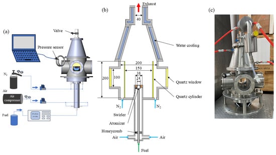
Figure 1.
Schematic of the high-pressure spray swirl-stabilized combustor (a), the main parameters of the combustor (b), and the real picture of the combustor (c).
The fuel is supplied by a constant flow pump (Beijing Xiangyue Huanyu,) with an accuracy of ±0.5%, regulating the fuel mass flow rate into the pressure atomizer (Danfoss, 80°, hollow). The flows of air and nitrogen (N2) are controlled by mass flow controllers (Alicat), each with an accuracy of ±0.1%. An axial swirler with eight vans is mounted at the exit of the burner, and the structure of the burner is carefully designed to allow for the replacement of the swirlers with different swirl numbers (SN). These swirlers share identical hub diameter (19 mm), tip diameter (38 mm), and vane thickness (2 mm) but feature different vane angles corresponding to different SN as listed in Table 1.

Table 1.
The investigated Swirl Flame conditions.
2.2. Flame Conditions
N-decane was used as the fuel and mixed with dry and clean air supplied by an air compressor. The swirl intensity can be classified by swirl number into 3 parts: weak swirl (SN ≤ 0.4), medium swirl (0.4 < SN ≤ 0.6), and high swirl (SN > 0.6) [39,40]. Five swirlers with vane angles of 20°, 30°, 43°, 50°, and 55° were used to study the influence of swirl intensity on flame structure and PAH formation, and the geometry of the swirlers is shown in Figure 2.
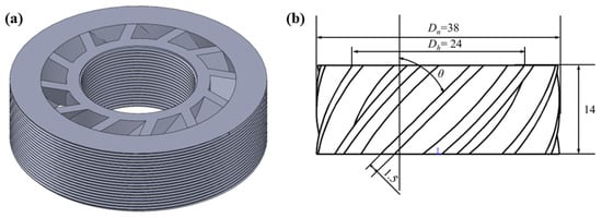
Figure 2.
(a) A 3D diagram of the swirler; (b) the geometric dimension of the swirler.
The corresponding SN is estimated based on the following equation [41,42]:
where Dh and Dn are the hub and tip diameters (mm) of the swirler geometry, and θ is the swirler vane angle. The operating condition is summarized in Table 1, and the SN of the experiments which covered the swirl intensity range from weak to strong was similar to that in the Refs. [5,13,43]. Moreover, S2, S3, and S5 were selected to further investigate the effect of pressure on the swirl spray flame. The experiments were conducted at pressures ranging from 1 to 3 bar, with pressure increments of 0.5 bar.
2.3. Laser Diagnosis
The optical measurements were performed 7 mm above the burner exit to avoid interference from laser scattering caused by liquid droplets. OH/PAH PLIF is used to measure flame structures and PAHs’ formation, and a schematic of the PLIF setup is shown in Figure 3. A frequency-doubled Nd:YAG laser (Continuum, Powerlite DLS 8010) with a laser wavelength of 532 nm, a frequency of 10 Hz, and energy of 600 mJ was used to pump a dye laser (Continuum, Vista FX-1). The output of the dye laser, with Rhodamine 590 dissolved in ethanol, was frequency-doubled to produce pulses at 283.35 nm, corresponding to the Q1(8) transition in the A2∑←X2∏ (1-0) band of the OH molecule. The same laser was utilized to excite PAH species. The uniformly distributed laser was shaped into a laser sheet (height = 5 mm, width = 500 µm) by a combination of a cylindrical lens (focus length = −30 mm) and a spherical lens (focus length = 500 mm). The pulse energy was 6 mJ, thus the laser fluence was estimated to be 0.02 J/cm2, with the fluorescence operated within the linear regime. Such low laser fluence could reduce the interference of soot [44,45].
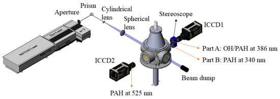
Figure 3.
Schematic of the experimental setup for OH-PLIF and PAH-PLIF measurements.
Because PAHs may also fluoresce in the ranges of 280–650 nm [46], interference from PAHs’ fluorescence in the OH collection system is inevitable, with a more pronounced impact at elevated pressures. Therefore, the OH and smaller PAH were simultaneously acquired using an emICCD (Princeton Instruments, PIMAX4) equipped with a UV lens (105 mm, ƒ/4.5 Nikon) and a stereoscope (Lavision, VZ-image) placed perpendicular to the laser sheet to collect the PLIF signals. The fluorescence of OH was captured in the range of 305–315 nm using a 310 nm narrow-band filter with FWHM of 10 nm (Alluxa) and a 305 nm long-pass filter (Andover, 305FG01-50). A 340 nm narrow-band filter with FWHM of 26 nm (Edmund) was used to collect the signals originating from two and three aromatic rings (A2 and A3) [47].
Since the fluorescence wavelengths of the PAHs are correlated with the molecular sizes of PAHs, the detection wavelength bands were determined based on [47,48]. Part A mounted a 386 nm narrow-band filter with FWHM of 27 nm (Edmund) to capture pyrene (A4) fluorescence. Part B of the stereoscope mounted a 340 nm narrow-band filter with FWHM of 26 nm (Edmund) to capture fluorescence of A2 and A3 both imaged by ICCD1 (emICCD, Princeton Instruments, PIMAX4). The ICCD2 (Princeton Instruments, PIMAX4) was equipped with a 525 nm narrow-band filter with FWHM of 25 nm (Edmund) to obtain the PLIF signals of acenaphthylene (A2R5) fluorescence. Details of cameras and filters are shown in Table 2.

Table 2.
Filters for simultaneous imaging.
The in-plane spatial resolutions for emICCD and ICCD were 0.22 × 0.22 mm2 and 0.10 × 0.10 mm2, respectively. The emICCD and ICCD were triggered by a digital Delay/Pulse Generator (Stanford Research Systems, DG535), and the gate widths of both emICCD and ICCD were set as 50 ns.
2.4. Image Processing
For each swirl spray flame, 200 simultaneous OH/PAH PLIF images were recorded, followed by 200 PAHs-PLIF images. Each set of simultaneously obtained images was corrected for the vertical variation in laser sheet intensity and aligned by a calibration image via pixel calibration. Subsequently, background subtraction was employed to remove the extraneous noise, and then a Gaussian filter was used to further improve the signal-to-noise ratio (SNR). The thresholds of images were determined using Otsu’s method [49] and then the images were binarized to find the contour of OH/PAH. The calculated thickness of the OH layer was based on these contours. The image size presented in this study is 200 × 507 pixels (approximately 100 × 50 mm).
3. Results and Discussion
3.1. Flame Structures
The time-averaged (200 shots) and instantaneous OH-PLIF with different SN are illustrated in Figure 4, combined with the simultaneously obtained PAH-PLIF (A2 and A3) contours, providing insights into the structures and the main reaction zone of swirl spray flames. The presented PAH-LIF profiles here serve to illustrate the interference of PAH on OH-PLIF spatially, and the intensity within the white contour was attributed to the combination of OH-PLIF and fluorescence of A2 and A3. The formation of PAH will be discussed in Section 3.3.

Figure 4.
Time-averaged (left) and instantaneous (right) images of OH-PLIF signal combined with PAH contour under different SN at 1 bar, (a–e) refers to the SN varied from 0.30 to 1.18. The contour of simultaneous fluorescence of A2 and A3 is depicted by white lines, and HAB denotes height above the burner.
In general, the flame shape changed from being thin and elongated to wider and shorter. Specifically, the flame structures were V-shaped with OH primarily distributed in the periphery of the spray jet, and an almost complete absence of OH signals inside the IRZ was observed except for S4 and S5. For S1–S3, the absence of OH signals in the IRZ indicates that the fuel droplets were essentially consumed in the flame branches, and the roll-up at the outside of the shear layer (SL) is easily discernible from instantaneous OH-PLIF images.
The flame opened with the increase in SN, consequently altering the flame structures. OH fluorescence was observed to appear within the IRZ as the value of SN exceeded 0.99 (i.e., S4). For S4 and S5, the shapes of the flame featured one or two upward bulges of the OH layer inside the “V” shape, ultimately transforming the flame shape into a crown-shaped configuration. This phenomenon might be due to the more intense evaporation and mixing process, the widening of the spray angle, and the higher concentration of large droplets near the core of the swirling with the increase in SN as indicated by [40,43].
The medium and strong SN were selected to study the influence of pressure on flame structure, as illustrated in Figure 5. It is evident that the OH region shortened for all three SN as the pressure increased from 1 to 3 bar, attributed to faster three-body recombination reactions depleting the OH concentration at higher pressure [7]. As the pressure increased, the OH distribution exhibited more frequent breaks and closures compared to atmospheric pressure. Although the time evolution is not depicted here, consecutive images revealed the potential for the closing of the breaks (i.e., reignition) and the development of new local extinctions. Furthermore, the increase in pressure altered OH structures and thinned the OH layer in three cases. As pressure increased, the area with higher OH signals gradually moved upstream, indicating that the primary reaction zone was closer to the nozzle, suggesting that increased pressure promoted a higher reaction rate. In the case of V-shaped flames (S2 and S3), an observation is that each OH layer separated into two branches, as indicated by the red circle in Figure 5c. Simultaneously obtained PAH-PLIF distributions demonstrated the increased formation of PAH located inside the OH layers. A similar feature can be seen in S5, where the outer branch also diverged under higher pressure (red circle in Figure 5m), and this bifurcation feature will be discussed in detail in Section 3.2.
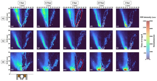
Figure 5.
Time-averaged (left) and instantaneous (right) images of OH-PLIF under different pressures and SN. Labels (a–e) correspond to case S2 with the pressures ranging from 1 to 3 bar, (f–j) and (k–o) show cases S3 and S5, respectively, under the same pressure range. The contour of PAH-PLIF (A2 and A3) is depicted with white lines.
3.2. Effect of Swirl Number and Pressure on OH Distribution
Figure 6 depicts the radical distribution of time-averaged OH-PLIF intensity at different pressures and HABs, normalized based on the maximum signal intensity at each pressure. The bimodal and symmetrical distributions of OH intensities along radical distance are easily observed. The slight asymmetry distribution of OH intensity at higher pressure was likely due to the laser sheet energy attenuation. The spikes of OH signal encircled by the green dashed line in Figure 6 were a result of the interference from droplets’ Raman-scattering, as the spotted intense signals in Figure 5.
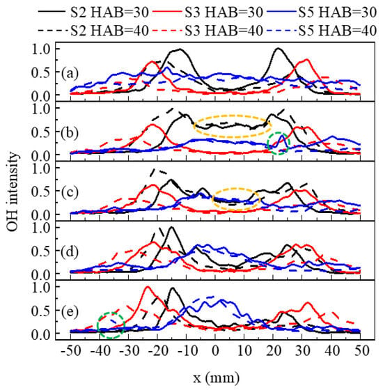
Figure 6.
The normalized time-averaged OH intensity at different HABs under pressures of (a) 1 bar, (b) 1.5 bar, (c) 2 bar, (d) 2.5 bar and (e) 3 bar.
In the case of S2 and S3 (V-shaped flames), the OH was mainly distributed in the periphery of the spray jet near the nozzle, and four peaks emerged with increasing pressure corresponding to the bifurcation structure. However, in the case of S2, the OH signal appeared in the IRZ at 1.5 bar and 2 bar, as encircled by the yellow dashed line in Figure 6, corresponding to the time-averaged part of Figure 5b and differing from the instantaneous one. Upon a detailed observation of images for S2 at 1.5 bar, the distinct distribution of time-averaged OH signals was attributed to the flame instability. Furthermore, the comparable OH intensity for S2 at HAB = 30 mm and HAB = 40 mm revealed that with a smaller SN, the reaction zone extended downstream owing to the poorer mixing quality of droplets and air. The lower mixing quality impacted the evaporation rate of the droplets [50,51], resulting in a higher OH signal intensity observed at a greater HAB in most cases with smaller SN as shown in Figure 4 and Figure 5. Additionally, the flame angles remained unchanged with increasing pressure, since the radical positions of the maximum OH intensity at different pressures were almost the same.
At 1 bar, the variation in the radical distribution of OH of S5 was smaller than S2 and S3, and the maximum OH intensity of S5 was the lowest. With the increase in SN, the increased centrifugal force on droplets promoted disturbance on the liquid sheet or ligament, causing the droplets to distribute more uniformly radially at an earlier stage, increasing the evaporation rate. Moreover, with the increase in pressure, the OH distribution of S5 became more compact, primarily within the IRZ. This is explained as being due to the movement of the droplets towards the IRZ with elevated pressure [52].
A double structure of the OH layer under higher pressure can be observed in Figure 5. The proportion of the bifurcated structure is shown in Figure 7, calculated by selecting the bifurcation feature of 100 instantaneous images to quantify the effect of pressure on the flame structure. The locations of newly generated OH branches are compared to those under lower pressures using the image process described in Section 2.4. It has been found that the newly generated branches were located in the inner region of the OH layer.
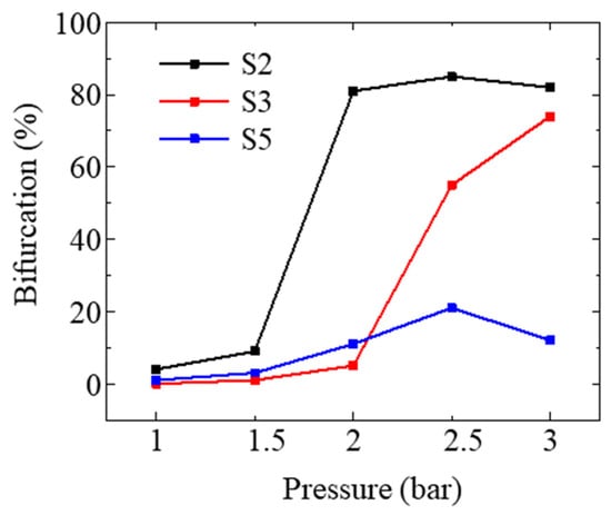
Figure 7.
The proportion of bifurcated structure in 100 instantaneous images under different pressures.
For medium SN, the OH layer exhibited a bifurcated structure at 1.5 bar, and this structure became more pronounced with increasing pressure, whereas the branch structures occurred at higher pressure with the increase in SN. The reduced proportion of bifurcation in S2 and S5 at 3 bar was probably due to the attenuation of the laser sheet and local extinction caused by flame instability. This combustion phenomenon resembled that of the spray structure under high pressure as described in [52]. One possible explanation for this phenomenon is that the negative correlation between pressure and the atomization cone angle led to poorer mixing quality, and the droplet distribution transitioned from hollow cone to solid cone as pressure increased [53]. However, the elevated pressure also resulted in smaller droplets [54], which were more prone to moving with the airflow. Consequently, unburned droplets, caused by poor mixing quality, were carried by the airflow to the IRZ and burned in this region. Additionally, higher SN with a more uniform radial distribution of droplets could alleviate the negative impact of increased pressure on mixing quality. Therefore, the bifurcation feature occurred at higher pressures as SN increased.
In premixed flames, the lifetime of the OH signal is too long to indicate the thickness of the reaction zone, whereas, in diffusion flames, OH radicals could quickly disappear on either side of the reaction zone [55], providing the ability to analyze the variation of reaction thickness with pressure. Probability density functions (PDFs) of the OH layer were computed for 100 instantaneous images and plotted in Figure 8 for the three SN under different pressures. To obtain the thickness of the OH layer, the edge of the OH region was identified using the same method as described in Section 2.4, then the longest line across the OH region at a certain HAB was defined as the OH layer thickness. It is evident that the OH layer is much thinner at higher HAB since droplets were gradually consumed as the flame developed downstream. The OH layer thickness decreased as pressure increased, which demonstrated a similar trend to the spray flame described in [56].
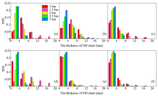
Figure 8.
PDF of the thicknesses of OH layer at different pressures, (a,d) is S2, (b,e) is S3, (c,f) is S5. The upper row is at HAB = 30 mm, and lower row is HAB = 40 mm.
3.3. Laser-Induced PAH Fluorescence
Figure 9 shows the time-averaged OH-PLIF and PAH-PLIF images for S1–S5, where the PAH-PLIF were acquired simultaneously using different central wavelength filters, and OH-PLIF was obtained from the same flame. As described previously, there is a positive correlation between the emitted wavelength and the size of PAH molecules, thus the PAH-LIF signal represents various PAH molecules with differing molecular sizes. The PAH-PLIF signals were observed upstream of the flame, and the distribution areas of these PAH signals exhibited significant overlap. By analyzing the contours of PAHs at different wavelengths, it is found that PAHs at larger wavelengths extended further downstream. Similar to OH, the PAHs displayed a V-shaped distribution in S1–S3 but were mainly situated on the outer side of the OH branches. This observation illustrates that PAHs formed along the fresh fuel/air stream [32]. However, with an increase in SN, the upstream PAHs extended radically towards the axis, which might be attributed to the increasing fuel concentration in the IRZ. In the cases of S1–S3, the PLIF of A2R5 showed no detectable fluorescence. As the increasing SN altered the structure of OH-PLIF, the distribution of PAHs also changed, with a sudden intensification in PAH-PLIF signals.
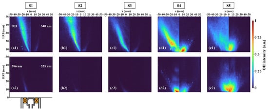
Figure 9.
Time-averaged images of OH-PLIF and PAH-PLIF with different SN at 1 bar, and (a–e) correspond to the cases S1–S5. (a1–e1) show OH-PLIF (left) and PAH-PLIF at 340 nm (right). (a2–e2) show PAH-PLIF at 386 nm (left) and PAH-PLIF at 525 nm (right).
The effect of pressure on PAH formation is depicted in Figure 10, and each molecular PLIF intensity is normalized by the maximum intensity among these cases. At elevated pressure, the area of PAH distribution still had considerable overlap, and the distribution area of each PAH increased with pressure. The increase in pressure did not change the V-shape feature of PAH in S2 and S3, but it promoted the PAH formation along the outer side of SL downstream and inside the IRZ near the nozzle. This enhanced effect of pressure was more significant on the formation of A2R5 compared to the other two PAHs. While for S5, the rising pressure changed the PAH generation region, the PAH branch along the SL gradually disappeared and occurred at the axis. This might be attributed to the poor mixing quality and more droplets moving to the IRZ.
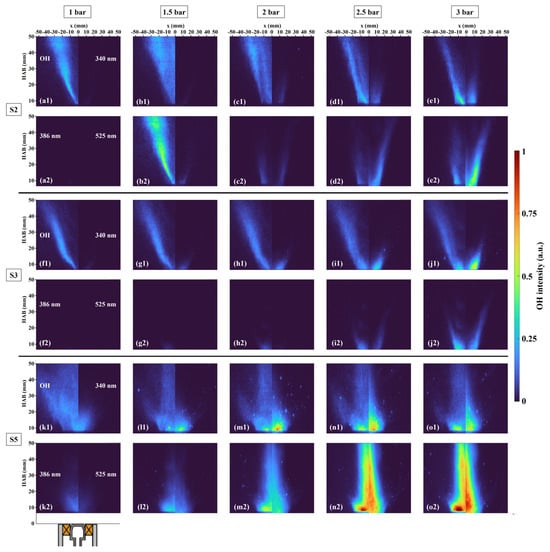
Figure 10.
Time-averaged images of OH-PLIF and PAH-PLIF at 1.0–3.0 bar. Labels (a–e) correspond to case S2 with the pressures ranging from 1 to 3 bar: (a1–e1) show OH-PLIF (left) and PAH-PLIF at 340 nm (right), while (a2–e2) display PAH-PLIF at 386 nm (left) and PAH-PLIF at 525 nm (right). Labels (f1–j1,f2–j2) and (k1–o1,k2–o2) represent cases S3 and S5, respectively, under the same pressure range and configuration.
The LIF intensity is influenced by various factors in addition to component concentration, such as laser energy, laser sheet size, temperature, and pressure. In this experiment, the LIF intensity was dependent on temperature, pressure, and component concentration. According to the simulation results from [57], changes in ambient pressure had no significant impact on temperature distribution. Besides, the negative correlation between pressure and LIF intensity implies that if the LIF intensity increases with pressure, the concentration of the component must increase strongly with pressure. Additionally, there is no evidence proving the quenching for a large PAH’s LIF is weaker than that of a smaller PAH’s LIF [35]. Hence, it is feasible to compare the LIF intensity of PAHs at different wavelengths.
As depicted in Figure 10, it is evident that the pressure enhanced the formation of three molecular sizes of PAHs. To further quantify the effect of pressure on PAHs with different molecular sizes, the ratios of maximum intensity of PAH-PLIF at a certain wavelength divided by that at another wavelength are calculated, as shown in Figure 11. The promoting effect of pressure on PAH-PLIF intensity at both 386/340 (A4/A2 and A3) and 525/340 (A2R5/A2 and A3) in S2 was more significant as pressure increased from 1.5 bar to 2.5 bar, but the growth rates of these two larger PAHs slowed down when the pressure reached 3 bar. The growth rates of PAHs at 340 nm and 386 nm were similar in S3, resulting in two inflection points on the curve, but overall, the growth rate of PAH at 386 nm was still greater than that of at 340 nm. For PAH at 525 nm, in both cases S3 and S5, there was no apparent increase in the ratio of 525/386, but when the pressure increased from 2 bar to 3 bar, the growth rate of A2R5 significantly accelerated. Moreover, the ratios of 386/340 and 525/340 increased by a maximum of 1.3 and 35.68 in S2, respectively. In S3, they were 0.37 and 4.78, and in S5, they were 0.92 and 2.46. This indicated that pressure had different degrees of promotion on PAHs with different molecular sizes, and the contribution of pressure to the PAH-PLIF intensity was more notable at longer wavelengths [35].
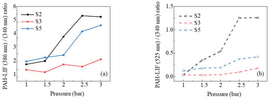
Figure 11.
Ratios of maximum PAH-LIF signals for case S2, S3, and S5 as a function of pressure. (a) 386 nm/340 nm, (b) 525 nm/340 nm.
4. Conclusions
The flame structures and evolution of PAHs with different molecular sizes were investigated in the swirl spray flames at elevated pressures with different swirl numbers, employing simultaneous OH-PLIF and PAH-PLIF measurements to eliminate PAH-induced interference in OH detection. The major findings in this study are as follows:
The influence of swirl number, ranging from weak to strong swirl, was systematically investigated. The flames exhibited two different structures, V-shaped and crown-shaped. In V-shaped flames, the distribution of PAHs was located on the outer side of the OH branches, while in crown-shaped flames, PAHs were more radically distributed and moved towards the axis. In both V-shaped and crown-shaped flames, the PAHs at different wavelengths overlapped significantly, but the PAH of different molecular sizes extended further downstream.
The pressure effect on the flame structure with different swirl numbers was different. Cases of S2, S3, and S5 were selected to study the pressure effects on the flame structure and PAHs’ formation characteristics. In V-shaped and crown-shaped flames, an increase in pressure led to a slight increase in the flame angle and a decrease in the thickness of the reaction layer. The OH layer exhibited a bifurcation structure with increasing pressure, and the newly generated OH branch was located in the inner region of the original OH layer.
Pressure enhanced PAH formation with stronger effects for PAHs with large molecular sizes. With increasing pressure, PAHs gradually extended downstream, and the upstream PAHs stretched towards the axis. In all three cases, PAH concentrations at three wavelengths increased with pressure, with larger PAHs exhibiting stronger pressure-enhanced phenomena.
Future work will focus on conducting experiments at higher pressures to enable a more comprehensive investigation of swirl spray flames, including spray characteristics, temperature distribution, and soot formation at elevated pressures. These studies aim to provide deeper insights into the fundamental mechanism of swirl-stabilized flame under high pressure conditions.
Author Contributions
Investigation, W.W. (Wenyu Wang), R.Z. and S.L.; Data curation, W.W. (Wenyu Wang); Writing—original draft, W.W. (Wenyu Wang); Writing—review & editing, W.W. (Wenyu Wang), R.Z., S.L., Y.H., W.W. (Wubin Weng), S.W., W.L.R. and Z.W.; Supervision, Y.H., W.W. (Wubin Weng) and Z.W.; Project administration, Z.W.; Funding acquisition, Z.W. All authors have read and agreed to the published version of the manuscript.
Funding
This work was supported by the National Key R&D Program of China (2023YFE0114400), the Fundamental Research Funds for the Central Universities (2022ZFJH04), and the ZJU-KAUST Joint Laboratory for Clean Combustion of E-fuels (JLACCE).
Data Availability Statement
The original contributions presented in the study are included in the article, further inquiries can be directed to the corresponding author.
Conflicts of Interest
The authors declare no conflict of interest.
Nomenclature
| ABE | Acetone-butanol-ethanol |
| HAB | Height above the burner |
| IRZ | Inner recirculation zone |
| LES | Large eddy simulations |
| LII | Laser-induced incandescence |
| PAHs | Polycyclic aromatic hydrocarbons |
| PDFs | Probability density functions |
| PIV | Particle image velocimetry |
| PLIF | Planar laser-induced fluorescence |
| PME | Palm biodiesel/methyl esters |
| PVC | Processing vortex core |
| SL | Shear layer |
| SNR | Signal to noise ratio |
| Dh | Hub diameter of the swirler (mm) |
| Dn | Tip diameter of the swirler (mm) |
| SN | Swirl number |
| θ | Swirler vane angle |
References
- Philo, J.J.; Shahin, T.T.; McDonald, C.T.; Gejji, R.M.; Lucht, R.P.; Slabaugh, C.D. Effect of fuel temperature on the structure of a high-pressure liquid-fueled swirl flame. Fuel 2023, 354, 129142. [Google Scholar] [CrossRef]
- Xin, S.; Wang, W.; He, Y.; Zhu, Y.; Wang, Z. Effect of low fuel temperature on combustion deterioration of kerosene swirling spray flames using OH-PLIF. Fuel 2024, 358, 130098. [Google Scholar] [CrossRef]
- Oberleithner, K.; Stöhr, M.; Im, S.H.; Arndt, C.M.; Steinberg, A.M. Formation and flame-induced suppression of the precessing vortex core in a swirl combustor: Experiments and linear stability analysis. Combust. Flame 2015, 162, 3100–3114. [Google Scholar] [CrossRef]
- Grader, M.; Eberle, C.; Gerlinger, P.; Aigner, M. LES of a Pressurized, Sooting Aero-Engine Model Combustor at Different Equivalence Ratios with a Sectional Approach for PAHs and Soot. In Turbo Expo: Power for Land, Sea, and Air; American Society of Mechanical Engineers: New York, NY, USA, 2018. [Google Scholar]
- Guiberti, T.F.; Zimmer, L.; Durox, D.; Schuller, T. Experimental Analysis of V- to M-Shape Transition of Premixed CH4/H2/Air Swirling Flames. In Turbo Expo: Power for Land, Sea, and Air; American Society of Mechanical Engineers: New York, NY, USA, 2013. [Google Scholar]
- Chterev, I.; Foley, C.W.; Foti, D.; Kostka, S.; Caswell, A.W.; Jiang, N.; Lynch, A.; Noble, D.R.; Menon, S.; Seitzman, J.M.; et al. Flame and Flow Topologies in an Annular Swirling Flow. Combust. Sci. Technol. 2014, 186, 1041–1074. [Google Scholar] [CrossRef]
- Strakey, P.; Woodruff, S.; Williams, T.; Schefer, R. OH-PLIF measurements of high-pressure, hydrogen augmented premixed flames in the simval combustor. In Proceedings of the 45th AIAA Aerospace Sciences Meeting and Exhibit, Reno, NV, USA, 8–11 January 2007; American Institute of Aeronautics and Astronautics: Washington, DC, USA, 2007; p. 980. [Google Scholar]
- Stopper, U.; Meier, W.; Sadanandan, R.; Stöhr, M.; Aigner, M.; Bulat, G. Experimental study of industrial gas turbine flames including quantification of pressure influence on flow field, fuel/air premixing and flame shape. Combust. Flame 2013, 160, 2103–2118. [Google Scholar] [CrossRef]
- Boxx, I.; Slabaugh, C.; Kutne, P.; Lucht, R.P.; Meier, W. 3kHz PIV/OH-PLIF measurements in a gas turbine combustor at elevated pressure. Proc. Combust. Inst. 2015, 35, 3793–3802. [Google Scholar] [CrossRef]
- Chterev, I.; Boxx, I. Effect of hydrogen enrichment on the dynamics of a lean technically premixed elevated pressure flame. Combust. Flame 2021, 225, 149–159. [Google Scholar] [CrossRef]
- Agostinelli, P.W.; Laera, D.; Chterev, I.; Boxx, I.; Gicquel, L.; Poinsot, T. Large eddy simulations of mean pressure and H2 addition effects on the stabilization and dynamics of a partially-premixed swirled-stabilized methane flame. Combust. Flame 2023, 249, 112592. [Google Scholar] [CrossRef]
- Rault, T.M.; Vishwanath, R.B.; Gülder, Ö.L. Influence of m-xylene addition to Jet A-1 on spray structure, flow field and soot production in turbulent swirl-stabilized spray flames in a model combustor. Combust. Flame 2020, 219, 258–267. [Google Scholar] [CrossRef]
- Cavaliere, D.E.; Kariuki, J.; Mastorakos, E. A Comparison of the Blow-Off Behaviour of Swirl-Stabilized Premixed, Non-Premixed and Spray Flames. Flow Turbul. Combust. 2013, 91, 347–372. [Google Scholar] [CrossRef]
- Chong, C.T.; Hochgreb, S. Spray flame structure of rapeseed biodiesel and Jet-A1 fuel. Fuel 2014, 115, 551–558. [Google Scholar] [CrossRef]
- Chong, C.T.; Chiong, M.-C.; Ng, J.-H.; Tran, M.-V.; Valera-Medina, A.; Józsa, V.; Tian, B. Dual-Fuel Operation of Biodiesel and Natural Gas in a Model Gas Turbine Combustor. Energy Fuels 2020, 34, 3788–3796. [Google Scholar] [CrossRef]
- Xie, T.; Chong, C.T.; Wang, S.; Seljak, T.; Ng, J.-H.; Tran, M.-V.; Karmakar, S.; Tian, B. Flow field, flame structure and emissions quantifications of oxygenated glycerol in a swirl flame combustor. Fuel 2022, 321, 124052. [Google Scholar] [CrossRef]
- Kumar, M.; Karmakar, S.; Chong, C.T. Investigation on combustion characteristics of acetone-butanol-ethanol/Jet A-1 mixture in a Swirl-stabilized combustor for its potential application in gas turbine engines. Fuel 2023, 340, 127610. [Google Scholar] [CrossRef]
- Philo, J.J.; Frederick, M.D.; Slabaugh, C.D. 100 kHz PIV in a liquid-fueled gas turbine swirl combustor at 1 MPa. Proc. Combust. Inst. 2021, 38, 1571–1578. [Google Scholar] [CrossRef]
- Chterev, I.; Rock, N.; Ek, H.; Emerson, B.; Seitzman, J.; Jiang, N.; Roy, S.; Lee, T.; Gord, J.; Lieuwen, T. Simultaneous imaging of fuel, OH, and three component velocity fields in high pressure, liquid fueled, swirl stabilized flames at 5 kHz. Combust. Flame 2017, 186, 150–165. [Google Scholar] [CrossRef]
- Malbois, P.; Salaün, E.; Rossow, B.; Cabot, G.; Bouheraoua, L.; Richard, S.; Renou, B.; Grisch, F. Quantitative measurements of fuel distribution and flame structure in a lean-premixed aero-engine injection system by kerosene/OH-PLIF measurements under high-pressure conditions. Proc. Combust. Inst. 2019, 37, 5215–5222. [Google Scholar] [CrossRef]
- Salaün, E.; Frindt, F.; Cabot, G.; Renou, B.; Richard, S.; Cazalens, M.; Malbois, P.; Grisch, F. Experimental Investigation on NO Pollutant Formation in High-Pressure Swirl-Stabilized Kerosene/Air Flames Using NO-, OH- and Kerosene-PLIF and PIV Laser Diagnostics. In Turbo Expo: Power for Land, Sea, and Air; American Society of Mechanical Engineers: New York, NY, USA, 2020. [Google Scholar]
- Legros, S.; Brunet, C.; Domingo-Alvarez, P.; Malbois, P.; Salaun, E.; Godard, G.; Caceres, M.; Barviau, B.; Cabot, G.; Renou, B.; et al. Combustion for aircraft propulsion: Progress in advanced laser-based diagnostics on high-pressure kerosene/air flames produced with low-NOx fuel injection systems. Combust. Flame 2021, 224, 273–294. [Google Scholar] [CrossRef]
- Lyu, Z.; Yan, T.; Qian, Y.; Cen, L.; Jin, Z.; Zhou, D.; Lu, X. Experimental and numerical investigation on soot formation characteristics in n-decane diffusion flames at elevated pressures. Proc. Combust. Inst. 2024, 40, 105628. [Google Scholar] [CrossRef]
- Wang, L.-Y.; Bauer, C.K.; Gülder, Ö.L. Soot and flow field in turbulent swirl-stabilized spray flames of Jet A-1 in a model combustor. Proc. Combust. Inst. 2019, 37, 5437–5444. [Google Scholar] [CrossRef]
- Al Sadi, K.; Nadimi, E.; Wu, D. Catalytic Ammonia Combustion: Legacy Catalytic Burner Designs and Catalyst Requirements for In Situ Hydrogen Production. Energies 2025, 18, 3505. [Google Scholar] [CrossRef]
- Shi, J.; Yang, P.; Ren, X.; Yang, X.; Yan, H.; Tan, Y.; Lei, Z. Study on the Mechanism of Soot Inhibition in Methanol-Ethylene Mixed Combustion under High-Pressure Conditions. Fuel 2025, 391, 134697. [Google Scholar] [CrossRef]
- Chen, C.; Liu, D. Review of effects of zero-carbon fuel ammonia addition on soot formation in combustion. Renew. Sustain. Energy Rev. 2023, 185, 113640. [Google Scholar] [CrossRef]
- Zeng, W.; Liu, J.; Liu, Y.; Chen, B.; Liu, A. The Effect of Hydrogen Addition on the Combustion Characteristics of RP-3 Kerosene/Air Premixed Flames. Energies 2017, 10, 1107. [Google Scholar] [CrossRef]
- Hui, X.; Zhang, C.; Xia, M.; Sung, C.-J. Effects of hydrogen addition on combustion characteristics of n-decane/air mixtures. Combust. Flame 2014, 161, 2252–2262. [Google Scholar] [CrossRef]
- Yan, Z.; Zhu, T.; Xue, X.; Liu, H.; Li, Q.; Huang, Z. Effects of NH3 and H2 addition on morphology, nanostructure and oxidation of soot in n-decane diffusion flames. Fuel Process. Technol. 2024, 253, 108003. [Google Scholar] [CrossRef]
- Li, R.; Yang, D.; Liu, F.; Hu, Q.; Liu, Q.; Yue, H.; Meng, Y.; Mei, Y. Study on in-cylinder soot formation process of F-T diesel/methanol dual-fuel diesel engine. Fuel 2025, 390, 134745. [Google Scholar] [CrossRef]
- Bouvier, M.; Cabot, G.; Yon, J.; Grisch, F. On the use of PIV, LII, PAH-PLIF and OH-PLIF for the study of soot formation and flame structure in a swirl stratified premixed ethylene/air flame. Proc. Combust. Inst. 2021, 38, 1851–1858. [Google Scholar] [CrossRef]
- Jain, A.; Wang, Y.; Schweizer, C.; Kulatilaka, W.D. Investigation of Flow-Flame Interactions in Kerosene Piloted Liquid-Spray Flames Using Simultaneous OH and PAH PLIF. In Proceedings of the AIAA Scitech 2020 Forum, Orlando, FL, USA, 6–10 January 2020; AIAA SciTech Forum. American Institute of Aeronautics and Astronautics: Washington, DC, USA, 2020. [Google Scholar]
- Wang, Y.; Jain, A.; Schweizer, C.; Kulatilaka, W.D. OH, PAH, and sooting imaging in piloted liquid-spray flames of diesel and diesel surrogate. Combust. Flame 2021, 231, 111479. [Google Scholar] [CrossRef]
- Liang, S.; Li, Z.; Gao, J.; Ma, X.; Xu, H.; Shuai, S. PAHs and soot formation in laminar partially premixed co-flow flames fuelled by PRFs at elevated pressures. Combust. Flame 2019, 206, 363–378. [Google Scholar] [CrossRef]
- Wan, K.; Huang, Y.; Gao, Z.; He, Y.; Jiang, C. Large-Eddy Simulation of a Swirling Aviation Kerosene Spray Flame Using 3-Component Surrogate Fuels. In Proceedings of the 32nd Congress of the International Council of the Aeronautical Sciences, Shanghai, China, 6–10 September 2021. [Google Scholar]
- Yi, R.; Chen, X.; Chen, C.P. Surrogate for Emulating Physicochemical and Kinetics Characteristics of RP-3 Aviation Fuel. Energy Fuels 2019, 33, 2872–2879. [Google Scholar] [CrossRef]
- Liu, J.; Hu, E.; Yin, G.; Huang, Z.; Zeng, W. An experimental and kinetic modeling study on the low-temperature oxidation, ignition delay time, and laminar flame speed of a surrogate fuel for RP-3 kerosene. Combust. Flame 2022, 237, 111821. [Google Scholar] [CrossRef]
- Balakrishnan, P.; Srinivasan, K. Influence of swirl number on jet noise reduction using flat vane swirlers. Aerosp. Sci. Technol. 2018, 73, 256–268. [Google Scholar] [CrossRef]
- Sharma, S.; Ghate, K.; Sundararajan, T.; Sahu, S. Effects of air swirler geometry on air and spray droplet interactions in a spray chamber. Adv. Mech. Eng. 2019, 11, 1687814019850978. [Google Scholar] [CrossRef]
- Gupta, A.K.; Lilley, D.G.; Syred, N. Swirl Flows; Tunbridge Wells: Kent, UK, 1984. [Google Scholar]
- Huang, Y.; Yang, V. Dynamics and stability of lean-premixed swirl-stabilized combustion. Prog. Energy Combust. Sci. 2009, 35, 293–364. [Google Scholar] [CrossRef]
- Bren˜a de la Rosa, A.; Wang, G.; Bachalo, W.D. The Effect of Swirl on the Velocity and Turbulence Fields of a Liquid Spray. J. Eng. Gas Turbines Power 1992, 114, 72–81. [Google Scholar] [CrossRef]
- Mulla, I.A.; Renou, B. Simultaneous imaging of soot volume fraction, PAH, and OH in a turbulent n-heptane spray flame. Combust. Flame 2019, 209, 452–466. [Google Scholar] [CrossRef]
- Liao, Y.-H.; Hermanson, J.C. OH-PLIF Imaging of the Reaction Zone in Swirled, Strongly-Pulsed Jet Diffusion Flames with a Low Reynolds Number. Combust. Sci. Technol. 2018, 190, 615–631. [Google Scholar] [CrossRef]
- Beretta, F.; D’Alessio, A.; D’Orsi, A.; Minutolo, P.U.V. and Visible Laser Excited Fluorescence from Rich Premixed and Diffusion Flames. Combust. Sci. Technol. 1992, 85, 455–470. [Google Scholar] [CrossRef]
- Liu, P.; He, Z.; Hou, G.-L.; Guan, B.; Lin, H.; Huang, Z. The Diagnostics of Laser-Induced Fluorescence (LIF) Spectra of PAHs in Flame with TD-DFT: Special Focus on Five-Membered Ring. J. Phys. Chem. A 2015, 119, 13009–13017. [Google Scholar] [CrossRef] [PubMed]
- Gao, Z.; Ren, F.; Cheng, X.; Wang, L.; Zhu, L.; Huang, Z. The effects of 1-methylnaphthalene addition to n-dodecane on the formation of soot and polycyclic aromatic hydrocarbons in laminar coflow diffusion flames. Fuel 2022, 329, 125378. [Google Scholar] [CrossRef]
- Otsu, N. A Threshold Selection Method from Gray-Level Histograms. IEEE Trans. Syst. Man Cybern. 1979, 9, 62–66. [Google Scholar] [CrossRef]
- Pakhomov, M.A.; Terekhov, V.I. Numerical modeling of turbulent flow structure and heat transfer in a droplet-laden swirling flow in a pipe with a sudden expansion. Numer. Heat Transf. Part A Appl. 2017, 71, 721–736. [Google Scholar] [CrossRef]
- Pakhomov, M.; Terekhov, V. The effect of droplets thermophysical properties on turbulent heat transfer in a swirling separated mist flow. Int. J. Therm. Sci. 2020, 149, 106180. [Google Scholar] [CrossRef]
- Shin, D.; Satija, A.; Lucht, R.P. Spray characteristics of standard and alternative aviation fuels at high ambient pressure conditions. Exp. Therm. Fluid Sci. 2022, 130, 110511. [Google Scholar] [CrossRef]
- Jasuja, A.K.; Lefebvre, A.H. Influence of Ambient Air Pressure on Pressure-Swirl Atomizer Spray Characteristics. In Turbo Expo: Power for Land, Sea, and Air; American Society of Mechanical Engineers: New York, NY, USA, 2001. [Google Scholar]
- Chigier, N.A. The Atomization and Burning of Liquid Fuel Sprays. In Energy and Combustion Science; Chigier, N.A., Ed.; Pergamon: New York, NY, USA, 1979; pp. 183–200. [Google Scholar]
- Cessou, A.; Stepowski, D. Planar Laser Induced Fluorescence Measurement of [ OH] in the Stabilization Stage of a Spray Jet Flame. Combust. Sci. Technol. 1996, 118, 361–381. [Google Scholar] [CrossRef]
- Allen, M.G.; McManus, K.R.; Sonnenfroh, D.M.; Paul, P.H. Planar laser-induced-fluorescence imaging measurements of OH and hydrocarbon fuel fragments in high-pressure spray-flame combustion. Appl. Opt. 1995, 34, 6287–6300. [Google Scholar] [CrossRef] [PubMed]
- Dekterev, A.A.; Lobasov, A.S.; Dekterev, A.A. Numerical simulation of unsteady combustion at elevated pressure and initial temperature of the mixture for the model combustion chamber. J. Phys. Conf. Ser. 2020, 1677, 012036. [Google Scholar] [CrossRef]
Disclaimer/Publisher’s Note: The statements, opinions and data contained in all publications are solely those of the individual author(s) and contributor(s) and not of MDPI and/or the editor(s). MDPI and/or the editor(s) disclaim responsibility for any injury to people or property resulting from any ideas, methods, instructions or products referred to in the content. |
© 2025 by the authors. Licensee MDPI, Basel, Switzerland. This article is an open access article distributed under the terms and conditions of the Creative Commons Attribution (CC BY) license (https://creativecommons.org/licenses/by/4.0/).