Abstract
Underground hydrogen storage (UHS) in geological formations offers a promising solution for large-scale energy buffering, but its long-term safety and mechanical stability remain concerns, particularly in fractured rock environments. This study develops a fully coupled thermo-mechanical model to investigate the cyclic response of a dual-cavern hydrogen storage system with polymer-based sealing layers. The model incorporates non-isothermal gas behavior, rock heterogeneity via a Weibull distribution, and fracture networks represented through stochastic geometry. Two operational scenarios, single-cavern and dual-cavern cycling, are simulated to evaluate stress evolution, displacement, and inter-cavity interaction under repeated pressurization. Results reveal that simultaneous operation of adjacent caverns amplifies tensile and compressive stress concentrations, especially in inter-cavity rock bridges (i.e., the intact rock zones separating adjacent caverns) and fracture-dense zones. Polymer sealing layers remain under compressive stress but exhibit increased residual deformation under cyclic loading. Contour analyses further show that fracture orientation and spatial distribution significantly influence stress redistribution and deformation localization. The findings highlight the importance of considering thermo-mechanical coupling and rock fracture mechanics in the design and operation of multicavity UHS systems. This modeling framework provides a robust tool for evaluating storage performance and informing safe deployment in complex geological environments.
1. Introduction
With the accelerating transition toward low-carbon energy systems, hydrogen has emerged as a critical energy vector due to its high energy density and ability to serve as both a fuel and an energy carrier [1]. However, large-scale implementation of hydrogen technologies hinges on the availability of reliable, safe, and cost-effective storage solutions [2]. Among various storage strategies, subsurface compressed hydrogen storage in geological formations offers a promising approach to accommodate seasonal demand fluctuations and buffer intermittent renewable power [3]. Compared with surface tanks, underground storage provides greater volumetric efficiency, enhanced safety, and potentially lower long-term costs [4]. While salt caverns have been successfully used for natural gas and are now being considered for hydrogen [5,6], their geological rarity and geographical limitations have prompted interest in alternative host media, such as hard rock caverns excavated in crystalline or sedimentary formations [7].
Hydrogen storage in engineered rock caverns presents a fundamentally different set of technical challenges compared to traditional salt caverns. The foremost difficulty lies in ensuring mechanical integrity under cyclic loading conditions [8]. Unlike halite, which deforms plastically and self-heals under pressure [9], hard rock formations are mechanically brittle and exhibit minimal capacity for stress redistribution [10]. This makes them far more susceptible to localized overstress, progressive damage accumulation, and instability during repetitive injection and withdrawal cycles. These mechanical challenges are particularly severe when gas pressure and temperature fluctuate simultaneously [11].
A second critical issue is geological discontinuity and heterogeneity [12]. Hard rock masses are seldom uniform: they are characterized by spatial variability in elastic properties and the presence of natural fractures [13]. These heterogeneities serve as mechanical weak zones that distort stress fields, concentrate strain, and potentially propagate damage during cyclic pressurization [14]. Moreover, they complicate the prediction of deformation patterns and the assessment of long-term stability [15]. While some numerical models incorporate homogeneous or simplified rock domains [16], such simplifications fail to capture the stress amplification, directional fracture interaction, and rock–liner decoupling effects that arise in actual fractured formations [17,18]. As such, the coupled impact of fracture distribution and mechanical heterogeneity remains a major uncertainty in current design practices [19].
Third, ensuring gas-tightness in a brittle, fractured environment presents yet another unresolved challenge [20]. Since natural rock cannot be relied upon to contain high-pressure hydrogen, engineered barriers, typically comprising a concrete liner and a sealing layer, are essential [21]. In particular, fiber-reinforced polymers (FRP) have gained attention for their chemical resistance and formability, but their performance under high-pressure hydrogen exposure is not fully understood [22]. FRP materials are semi-permeable and susceptible to hydrogen diffusion, especially under elevated temperatures and prolonged cyclic loading [23]. Over time, this may lead to leakage accumulation or microstructural fatigue, jeopardizing storage safety [24]. Most existing models assume perfect sealing, which does not reflect the physics of hydrogen permeation through polymers under stress. Therefore, the long-term thermo-mechanical and sealing behavior of FRP layers remains poorly constrained, especially when operating in conjunction with a heterogeneous rock mass and fractured boundary conditions.
Furthermore, as the scale of underground hydrogen storage expands, multi-cavern configurations are increasingly favored to meet growing energy demands and operational flexibility [25]. However, this introduces a new layer of complexity in the form of inter-cavern mechanical interactions [26]. When two or more storage chambers are operated in parallel, their pressure fields, deformation zones, and thermal gradients begin to overlap within the shared rock mass, giving rise to coupled stress evolution that is fundamentally different from isolated cavern behavior [27]. This interaction can lead to stress amplification in the interstitial rock bridge, exacerbate displacement fields, or induce asymmetric loading on the liner and sealing structures [28].
The consequences are particularly pronounced in fractured and heterogeneous rock media [29], where mechanical disturbances propagate in non-intuitive ways. Localized stress concentrations around fractures can shift dynamically as pressurization progresses in both chambers, increasing the likelihood of fracture slip or reactivation [30]. These processes not only affect mechanical stability but may also compromise gas containment, especially if sealing layers experience amplified cyclic loading from both sides [31]. The situation is further complicated by thermo-mechanical coupling: temperature fluctuations during gas injection and withdrawal introduce transient expansion and contraction in both the rock and structural components [32]. These thermal effects delay stress dissipation and may lead to residual deformation in critical zones [33]. Despite their practical significance, most existing studies focus on single-cavern systems or assume idealized geological conditions [34]. As a result, the multi-physics coupling mechanisms that govern dual-cavern performance remain poorly understood. This creates a critical knowledge gap in the safe and efficient design of next-generation hydrogen storage infrastructure.
To address these unresolved challenges, this study proposes a fully coupled thermo-mechanical modeling framework for subsurface hydrogen storage in a dual-cavern system embedded within fractured, heterogeneous rock formations. The model captures the transient evolution of pressure, temperature, stress, and displacement during cyclic hydrogen injection and withdrawal under non-isothermal boundary conditions. Geological heterogeneity is incorporated through a stochastic Weibull distribution of Young’s modulus [35], while explicit fracture networks are embedded to reflect discontinuities in the rock mass [35]. The polymer-based FRP sealing layer is modeled as a semi-permeable membrane, with hydrogen permeation governed by a Darcy-like transport law modified for gas-phase diffusion through polymers [36]. Compared with previous studies that lacked attention to the crack conditions of rocks [17,20], including our own prior work focusing solely on the thermodynamic behavior of single-cavern systems with different sealing materials [20], the present study introduces several critical advancements. These include the (1) explicit modeling of fracture networks based on stochastic geometry, (2) incorporation of spatial heterogeneity in rock stiffness using a three-parameter Weibull distribution, and (3) simulation of mechanical coupling between adjacent storage caverns operating synchronously. Unlike previous simplified or isolated configurations, this integrated thermo-mechanical framework provides a more comprehensive and realistic evaluation of stress redistribution, deformation localization, and long-term containment risks in fractured and heterogeneous rock environments.
Two operational scenarios are considered: a single-cavern baseline case and a dual-cavern scenario with synchronized pressurization, enabling the systematic investigation of inter-cavity mechanical interaction, stress redistribution, and fracture reactivation risks. This work aims to quantify the influence of dual-cavern operation on local stress amplification and identify critical zones of mechanical vulnerability arising from geological heterogeneity. The findings offer mechanistic insights into the complex interaction among gas dynamics, rock deformation, and fracture behavior, providing a foundation for the design and safety assessment of future large-scale underground hydrogen storage systems in fractured hard rock environments.
The structure of this study is as follows: Section 2 presents the governing equations and thermodynamic model for hydrogen injection and withdrawal cycles. Section 3 describes the numerical implementation, material characterization, and validation strategy. Section 4 discusses the simulation results under both single- and dual-cavern operating conditions, focusing on stress evolution, deformation behavior, and fracture responses. Finally, Section 5 summarizes the main conclusions and implications for the engineering of subsurface hydrogen storage.
2. Thermodynamic Modeling of Hydrogen Injection and Withdrawal Cycles in Underground Storage Caverns
To capture the dynamic thermodynamic response of hydrogen during the pressurization and withdrawal phases in underground storage caverns, this study employs a semi-analytical framework built upon classical conservation principles and the ideal gas law. The approach is inspired by Kushnir et al. [37], who established coupled mass and energy balance equations for sealed gas enclosures. Although this model assumes uniform pressure and temperature distributions within the cavern, it offers adequate accuracy for engineering-scale simulations, particularly for large underground hydrogen storage projects.
2.1. Mass and Energy Balances
The temporal evolution of hydrogen density is governed by a mass conservation equation that accounts for both injection and production flows, as well as minor leakage effects. Similarly, the internal energy and temperature changes are described by an energy balance, reflecting mechanical work (compression and expansion) and heat transfer interactions with the enclosing rock [38]. The coupled governing equations can be generally expressed as:
where V is the volume of the cavern, ρ is the gas density inside the cavern, and (Fi + Fe) mie denotes the total mass flow rate. Fi and Fe represent injection and extraction flow rates, respectively, and mie is the individual gas mass flow rate. cv is the specific heat capacity at constant volume, Tc is the temperature of hydrogen inside the cavern, Rc is the specific gas constant for hydrogen, Z is the compressibility factor, h is the specific enthalpy, u is the specific internal energy, and Q is the heat transfer rate between the gas and the surrounding rock.
The dynamic operation cycle is illustrated in Figure 1. Here, the mass flow ratio between discharge and charge is set at 2, and ml denotes gas leakage through the chamber wall. The operation is divided into four stages with the durations t1 = 8 h, t2 = 12 h, t3 = 16 h, and t4 = 24 h [39].
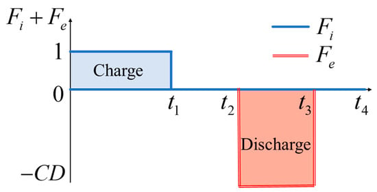
Figure 1.
Function image of Fi and Fe within one cycle (adapted from [20]).
2.2. Gas State and Thermodynamic Properties
The thermodynamic behavior of hydrogen in the chamber is approximated using the ideal gas law, where the compressibility factor (Z) introduces pressure–temperature dependence for engineering accuracy:
where Ti represents the temperature during gas injection; Z0, cv0, and cp0 are the reference values of the compressibility factor, specific heat at constant volume, and specific heat at constant pressure, respectively [25]; and ZT is the partial derivative of Z with respect to temperature [10]. ρ0 and T0 are the reference density and temperature, respectively, used for empirical correlation.
2.3. Heat Transfer Mechanisms
During each operational stage, heat transfer occurs between the stored gas and the surrounding geologic media, combining both convection and conduction. The net heat exchange through the chamber boundary is evaluated as:
where hc is the heat transfer coefficient, Ac is the internal surface area, Tt is the temperature of the surrounding rock, and Tc is the instantaneous gas temperature inside the chamber [40].
2.4. Gas Leakage Modeling
Distinct from traditional steel-lined caverns, the investigated system incorporates a fiber-reinforced polymer (FRP) sealing layer, which retains low permeability while still permitting limited hydrogen diffusion under elevated pressure. Steel linings are treated as effectively impermeable, while FRP allows negligible leakage. The permeability coefficient of FRP is defined as 1 × 10⁻¹⁹ m2 [20]. The leakage flux is modeled using a simplified form of Darcy’s law applicable to gas transport through thin polymer membranes. Unlike the classical differential form of Darcy’s law, this formulation uses an effective permeability coefficient (λ), which is determined experimentally and implicitly incorporates the effects of gas viscosity, membrane porosity, and microstructure. The gas flow rate is calculated under the assumption of a constant pressure gradient across the membrane thickness (hm), and the cross-sectional area is absorbed into the formulation. Therefore, viscosity does not appear explicitly, but its influence is embedded in λ. This approach is widely used for semi-permeable polymer layers under steady-state or quasi-steady gas diffusion conditions [36]:
where ρs is the gas density at 273.15 K and 1 atm, λ and hm represent the permeability coefficient and thickness of the FRP sealing material, and Ps is the gas pressure outside the polymer sealing layer. Ps is assumed to be constant at atmospheric pressure and is not coupled to pore pressure in the surrounding rock. Due to the much lower permeability of FRP relative to the surrounding rock, leakage is minimal and does not notably impact the external pore pressure, assumed to remain atmospheric. While modeled via Darcy’s law for simplicity, FRP materials are subject to hydrogen-induced effects such as diffusion-driven swelling, embrittlement, and microstructural fatigue, particularly under cyclic thermal conditions [41,42]. Recent advances have also addressed gas transport in fractured reservoirs using numerical models that incorporate non-Darcy flow behavior and multiphase gas components [43]. These approaches have shown the importance of accounting for complex flow dynamics in heterogeneous porous media. Although our model simplifies leakage through the FRP layer as quasi-steady single-phase flow, the underlying physical assumptions are conceptually aligned with these broader flow mechanisms in fractured systems.
2.5. Rock Mass Thermo-Mechanical Response
The strain in the surrounding non-isothermal rock εij and force equilibrium are described by [20,44]:
where G is the shear modulus and G = E/2 (1 + v), and E and v are the Young’s modulus of the rock and the Poisson’s ratio, respectively. αT is the volume expansion coefficient, and ΔT = T − T0 is the relative temperature compared to the initial temperature T0. ui is the displacement in the i direction, and fi is the unit volume force in the i direction.
3. Establishment and Verification of Hydrogen Storage Model
To investigate the mechanical and thermal responses of underground hydrogen storage systems under realistic geological conditions, a numerical model incorporating dual storage chambers and randomly distributed rock fractures was developed using COMSOL Multiphysics (version 6.2). The model accounts for non-isothermal conditions and cyclic pressurization, reflecting the transient behavior of hydrogen injection and withdrawal processes.
To reduce computational cost while maintaining accuracy, local mesh refinement is applied within a 20 m radius around each cavern, based on the findings of Sun et al. [45], who reported that the influence zone of tunnel deformation typically does not exceed this range. As shown in Figure 2, the computational domain measures 50 m × 50 m, within which two circular chambers are embedded. Chamber 1 has a diameter of 5 m, while Chamber 2 has a diameter of 4 m. Each chamber is surrounded by a multilayer structure comprising an inner sealing layer, a lining layer, and the natural surrounding rock. The sealing layer, constructed using fiber-reinforced polymer (FRP), is primarily responsible for preventing hydrogen leakage and partially transmitting internal stress. The lining layer offers structural support and directly interfaces with the host rock, which is assumed to contain randomly distributed fractures. These fractures are generated according to a stochastic distribution to reflect the heterogeneity and discontinuity inherent in deep geological formations.
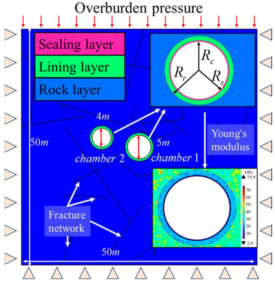
Figure 2.
Schematic of the dual-cavern hydrogen storage model with boundary conditions, fractures, and material layers. The black straight lines in the model together form the fracture network. (Adapted from [20]).
The material heterogeneity of the surrounding rock and concrete is modeled using a three-parameter Weibull distribution for Young’s modulus, which captures the variability of mechanical properties caused by microstructural inconsistencies and the presence of fractures. Previous studies have confirmed the feasibility of the Weibull distribution [46,47]. The elastic modulus E follows a three-parameter Weibull distribution, and its probability density function and distribution function are expressed as follows:
where βw is the shape parameter, αw is the scale parameter, and μw is the position parameter. This paper takes 2.41, 1.073, and 0.296, respectively [20]. The spatial variation in Young’s modulus is illustrated in Figure 2, where it can be seen that lower-stiffness regions are concentrated near fracture clusters and material interfaces.
The model incorporates overburden pressure applied at the top boundary to simulate geological loading conditions. Roller constraints are applied to the lateral and bottom boundaries to suppress rigid body motion, ensuring numerical stability. Heat transfer and mechanical deformation are simultaneously solved under cyclic hydrogen charging and discharging, allowing for the investigation of thermo-mechanical coupling effects. Two operating scenarios are considered: in the first, only Chamber 1 is used for hydrogen storage; in the second, both chambers are operated simultaneously. The fracture network is considered static throughout the simulation to reduce computational complexity and isolate mechanical responses. While this approach captures stress amplification near fractures, it does not simulate fracture propagation or slip. This comparative approach enables the assessment of inter-chamber interaction, pressure interference, and fracture reactivation risks under dual-chamber operation.
The governing equations were discretized using the finite element method (FEM) within COMSOL Multiphysics (version 6.2). The computational domain was meshed using a free triangular mesh, with local refinement applied within a 20 m radius around each storage chamber to capture stress concentration and thermal gradients. The final mesh contained approximately 122,000 elements. A mesh sensitivity analysis was performed by refining the mesh and comparing results; variations in displacement and stress were found to be within 2%, confirming mesh convergence.
A time-dependent simulation was conducted using the generalized-α solver to ensure stability under cyclic thermo-mechanical loading [47]. The thermal and structural physics were fully coupled and solved simultaneously. Initial conditions assumed geostatic equilibrium and uniform temperature corresponding to the geological baseline. Boundary conditions included roller constraints on the lateral and bottom boundaries and a uniform overburden pressure on the top boundary. Simulations were run on a workstation equipped with an Intel Core i9-14900KF CPU and 64 GB RAM, providing sufficient computational power for the fully coupled model.
To ensure the reliability and accuracy of the proposed numerical model for underground hydrogen storage, a series of validation simulations were conducted. The model was benchmarked against previous thermos–fluid–solid coupling studies, most notably the work of Chen and Wang [46], who established a compressed air energy storage (CAES) model based on the coupled solution of gas flow, heat transfer, and structural mechanics. In their study, time-dependent pressure and temperature fields were obtained by solving governing equations and subsequently applied as boundary loads on the cavern wall to evaluate mechanical responses during cyclic gas injection and withdrawal.
In the present study, similar operational conditions were adopted to facilitate comparison. The hydrogen (or air) injection and release were modeled as transient processes with an injection rate of 100 kg/s and a release rate of 200 kg/s, followed by a dwell period to allow the system to stabilize. The simulation accounted for non-isothermal conditions and mechanical deformation and used the thermodynamic and physical parameters listed in Table 1 and Table 2. These include specific heats, gas constants, and critical states for air and hydrogen, as well as thermal and mechanical properties of the solid materials (steel, FRP, concrete, and rock). The compressed air energy storage parameters use a steel lining, a lining layer, and the surrounding rock, with air as the gas. The compressed hydrogen energy storage parameters use an FRP sealing, a lining layer, and the surrounding rock, with hydrogen gas as the gas.

Table 1.
The parameters of air and hydrogen used in numerical simulation models.

Table 2.
Other parameters used in numerical simulation models.
Figure 3 presents the comparison of simulation results from this study with those from Sun’s [47], Kim’s [48], and Chen’s models [46]. The comparisons are made in terms of three critical variables at the cavern wall: stress, temperature, and displacement, plotted over a 24 h cycle. The results show excellent agreement across all variables. The stress evolution exhibits a steady increase during gas injection, a plateau during pressurization, and a sharp decrease during gas release, closely matching the reference data. Temperature exhibits a characteristic “rise–drop–drop–rise” pattern, reflecting the thermal dynamics of gas compression and expansion. Displacement, governed by thermo-mechanical coupling, also shows consistent behavior with prior studies, including elastic expansion during charging and contraction during discharging.
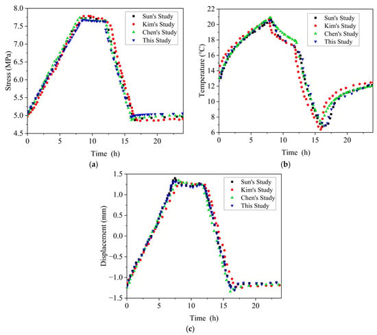
Figure 3.
Comparison of simulated stress (a), temperature (b), and displacement (c) at the cavern wall between this study and previous models [46,47,48].
To quantitatively assess the model accuracy, we compared our simulation results with reference datasets from previous studies. The mean absolute errors (MAEs) for the stress, temperature, and displacement profiles were calculated to be 1.16 MPa, 3.82 °C, and 0.36 mm, respectively. These low error values indicate that the simulation framework achieves a high level of agreement with observations, thereby validating its reliability for predicting coupled thermo-mechanical responses.
Although the accuracy of the proposed simulation framework has been established through comparisons with established air-based compressed gas energy storage models, it remains necessary to assess its applicability to hydrogen-specific conditions. To this end, additional validation was performed using experimental data from Li et al. [49], who studied the thermal behavior of hydrogen during high-speed filling processes.
The referenced experiment involved a high-pressure hydrogen cylinder with a length of 1.748 m and an internal diameter of 0.167 m, featuring a dual-layer wall composed of a 5 mm polymer liner and a 15 mm steel shell. Hydrogen was injected at a rate of 14 g/s, with the initial temperature maintained at 20 °C. A convective heat transfer coefficient of 8 W/(m2·K) was used to characterize the thermal exchange between the gas and the vessel wall. Using these experimental conditions, a transient simulation was carried out to reproduce the hydrogen filling process.
As shown in Figure 4, the predicted temperature variation from this study is compared with experimental results and the numerical findings of Hu et al. [3], who previously validated a similar model. The results show that the simulated temperature curve in this study aligns well with both the experimental measurements and Hu et al.’s model, particularly during the initial rapid rise in temperature and the gradual approach to thermal equilibrium. This strong correlation reinforces the accuracy of the thermal parameters used for hydrogen in the model and confirms its reliability for simulating rapid pressurization events in hydrogen storage systems. The rapid initial temperature rise is primarily due to adiabatic compression, while the gradual plateau reflects the dominance of convective heat transfer to the tank wall.
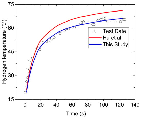
Figure 4.
Comparison of hydrogen temperature evolution during rapid filling: experimental data and simulation results [3].
4. Results and Discussion
To gain a comprehensive understanding of the thermo-mechanical behavior of the underground hydrogen storage system, numerical simulations were conducted under two operational scenarios: (1) only Chamber 1 is active during the charging and discharging cycles, and (2) both Chamber 1 and Chamber 2 are operated simultaneously. This section presents a detailed analysis of the simulation results, focusing on the spatial and temporal variations of mechanical stress and displacement in key structural components. Specifically, the first principal stress, third principal stress, and total displacement are examined using both time-history plots and contour distributions. The results are used to compare the local responses of the sealing layer, lining layer, and surrounding rock under different working conditions, and to assess the mechanical interaction between adjacent chambers. The influence of dual-chamber operation on stress redistribution, deformation characteristics, and potential risk zones is discussed in detail.
4.1. Evolution of First Principal Stress
Figure 5 illustrates the time evolution of the first principal stress in key structural components—namely, the sealing layer, lining layer, and surrounding rock—under two operating conditions: (a) single-chamber operation, where only Chamber 1 is pressurized, and (b) dual-chamber operation, where both chambers are activated simultaneously.
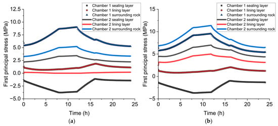
Figure 5.
Time-history plots of the first principal stress in the sealing layer, lining layer, and surrounding rock under (a) single-chamber operation and (b) dual-chamber operation.
During the single-chamber operation, Chamber 1 experiences a typical tensile response in the surrounding rock as gas injection progresses. The tensile stress in the rock increases steadily, reaching a peak of approximately 8.9 MPa at around 12 h. This reflects the radial expansion of the chamber cavity and associated rock deformation. The lining layer exhibits a more moderate tensile response, peaking at 1.8 MPa, indicating its buffering role in dissipating internal pressure. In contrast, the sealing layer remains under compression throughout the cycle, with a minimum stress of approximately −4.0 MPa, helping to ensure containment and sealing integrity under pressure loading.
Although Chamber 2 is inactive in this scenario, its structural components show a measurable passive response. The sealing layer and surrounding rock of Chamber 2 undergo slight tensile stress peaks of approximately 3.4 MPa and 5.2 MPa, respectively. This indicates that the stress field generated by Chamber 1 propagates through the surrounding rock mass, inducing mechanical coupling effects that extend beyond the immediate cavity.
Under dual-chamber operation, both chambers are pressurized and depressurized in a synchronized manner. Compared to the single-chamber case, the tensile stress in the surrounding rock of Chamber 1 increases significantly, reaching a peak of 11.36 MPa. The stress in the lining layer also rises slightly, while the sealing layer maintains compressive behavior with a minimum stress similar to the single-chamber case. Notably, the stress field in Chamber 2 mirrors that of Chamber 1, with its surrounding rock reaching a tensile peak of 9.4 MPa. The near-symmetric response between the two chambers confirms strong mechanical interaction during concurrent operation.
These results demonstrate that dual-chamber operation amplifies the overall tensile stress, especially in the surrounding rock, while maintaining stable compressive conditions in the sealing layers. The increased stress magnitude and overlapping influence zones highlight the necessity of considering chamber spacing, synchronous load control, and rock mass coupling effects when designing multi-cavern hydrogen storage systems to prevent local overstress or fatigue-induced damage.
4.2. Evolution of Third Principal Stress
Figure 6 illustrates the time history of the third principal stress—representing the maximum compressive stress—within the sealing layer, lining layer, and surrounding rock of both chambers, under single- and dual-chamber operation. This parameter is crucial for evaluating confinement capacity, risk of compressive failure, and long-term mechanical stability of underground hydrogen storage systems.
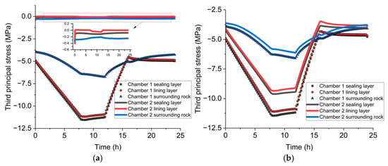
Figure 6.
Time-history plots of the third principal stress in the sealing layer, lining layer, and surrounding rock under (a) single-chamber operation and (b) dual-chamber operation. Negative σ3 values indicate compressive stress.
Under single-chamber operation, Chamber 1 exhibits a typical compressive response in all structural layers. The sealing layer shows the most significant reduction in stress, reaching a minimum of approximately −11.5 MPa at the peak injection phase (10–12 h), due to the combined effect of internal pressure and rock constraint. The lining layer follows closely with a minimum stress of −11.1 MPa, while the surrounding rock registers a peak compressive stress of approximately −6.7 MPa, indicating a more moderated stress response. After the onset of discharge, the compressive stress gradually recovers across all layers, suggesting an elastic unloading process. Although Chamber 2 remains inactive, its structural components still show weak passive responses. The compressive stress in its sealing and lining layers remains within ±0.4 MPa, reflecting low-level mechanical coupling through the surrounding formation.
In the dual-chamber operation case, both chambers undergo synchronized pressurization and depressurization. The compressive stress distribution becomes more uniform and symmetric across the system. In Chamber 1, the sealing and lining layers reach peak compressive stresses of −11.4 MPa and −11.0 MPa, respectively, comparable to the single-chamber case. In Chamber 2, these layers exhibit slightly lower peak compressive stresses of −9.5 MPa and −9.3 MPa, indicating full mechanical participation, though with marginally reduced confinement due to spatial offset or local heterogeneity. The surrounding rock reaches compressive values of −6.5 MPa in Chamber 1 and −6.1 MPa in Chamber 2, consistent with the expected stress transfer between the two cavities. Compared to the single-chamber case, the dual-chamber scenario results in a more balanced compressive stress field and a more synchronized unloading process across all structural layers. The gradual stress recovery observed in both chambers during discharge suggests that mutual confinement and thermal inertia slow down stress release, which may help stabilize structural behavior but could also contribute to time-dependent deformation such as creep.
Overall, the results highlight that while dual-chamber operation does not significantly increase peak compressive stress, it enhances inter-cavity mechanical interaction, leading to more homogeneous stress states. This finding reinforces the need to consider multi-chamber coupling effects in the long-term mechanical design of underground hydrogen storage systems.
4.3. Displacement Response
Figure 7 presents the temporal evolution of radial displacement in the sealing layer, lining layer, and surrounding rock for both chambers under two operational conditions. Displacement reflects the combined effects of internal pressure, structural stiffness, and thermo-mechanical coupling, and is a direct indicator of cavity deformation and stability.
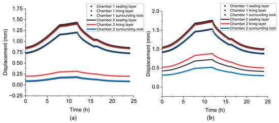
Figure 7.
Time-history plots of displacement in the sealing layer, lining layer, and surrounding rock under (a) single-chamber operation and (b) dual-chamber operation.
Under the single-chamber operation scenario, Chamber 1 exhibits a progressive increase in radial displacement during the gas injection phase. The maximum displacement is observed at approximately 12 h, coinciding with the peak internal pressure. The sealing layer shows the largest deformation, reaching approximately 1.43 mm, followed by the lining layer at approximately 1.40 mm, and the surrounding rock at approximately 1.21 mm. This gradation reflects the varying stiffness of each layer, with softer materials deforming more under equivalent load. During the discharge phase, the displacements gradually decrease, demonstrating an elastic recovery trend, although minor residual deformation remains. In contrast, Chamber 2, although inactive in this scenario, experiences minimal passive displacement. The lining layer undergoes peak displacements of less than 0.3 mm, and the sealing layer and the surrounding rock deform by less than 0.2 mm.
Under dual-chamber operation, both chambers undergo coordinated pressurization, resulting in significantly higher and more symmetric deformation across all components. In Chamber 1, the sealing layer reaches a peak displacement of approximately 1.75 mm, with the lining and surrounding rock layers following at 1.73 mm and 1.52 mm, respectively. A similar displacement pattern is observed in Chamber 2, with only slightly lower peak values due to possible localized stiffness differences or geometric effects.
Compared to the single-chamber case, the displacement responses in both chambers are markedly enhanced during dual operation. Notably, the residual displacement after discharge is also higher, indicating possible accumulated plastic deformation or thermal lag effects in the materials. The dual-chamber operation amplifies total deformation but maintains structural coherence across the system. While all components remain within safe deformation limits, the increased displacement highlights the need for careful material selection, particularly for sealing layers, and monitoring strategies for long-term operational reliability.
4.4. Contour Analysis of First Principal Stress
To complement the time-history data, Figure 8 presents the spatial distribution of the first principal stress (σ1) at key time intervals (0 h, 8 h, 12 h, 16 h, and 24 h) under two operational modes: (a) single-chamber operation and (b) dual-chamber operation. These contours provide valuable insight into the localization and propagation of tensile stresses during hydrogen injection and withdrawal.
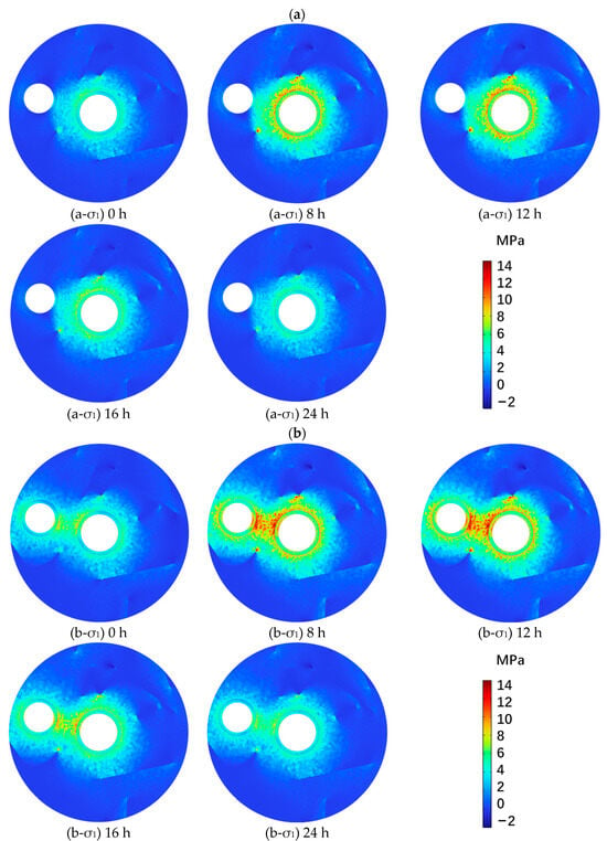
Figure 8.
Contour distribution of first principal stress (σ1) at different times under (a) single-chamber operation and (b) dual-chamber operation.
Under single-chamber operation, tensile stress is primarily concentrated around Chamber 1, with a circular pattern that intensifies as pressure builds. At 0 h, the system is in equilibrium with negligible tensile stress. By 8 h, as the injection proceeds, a distinct tensile ring forms around Chamber 1’s boundary. This ring becomes more pronounced at 12 h, when the internal pressure peaks. The highest tensile stress, exceeding 10 MPa, is localized near the liner–rock interface and propagates radially outward into the fractured rock zone. As pressure is released during the discharge phase (16 h to 24 h), the stress field gradually dissipates and returns to near-initial levels, confirming the elastic nature of the deformation.
Under dual-chamber operation, both chambers exhibit intense and overlapping tensile stress fields during the pressurization phase. At 8 h and 12 h, stress contours from Chamber 1 and Chamber 2 merge, forming a high-stress corridor between the two cavities. This interaction zone shows significantly elevated σ1 values, reaching up to 14 MPa, indicating mechanical superposition and stress amplification due to inter-cavity coupling. The stress concentration is not only stronger but also more spatially extensive than in the single-chamber case. At 16 h and 24 h, the stress field contracts, but residual tension persists in the inter-chamber region, potentially increasing the risk of fracture reactivation or propagation.
These findings confirm that dual-cavern operation significantly alters the stress field topology, with higher tensile magnitudes and broader affected zones. Such inter-cavity effects underscore the need for cautious spacing and stress-management strategies in multi-chamber hydrogen storage systems, especially when deployed in fractured or jointed rock masses.
4.5. Contour Analysis of Third Principal Stress
To further understand the compressive behavior in the hydrogen storage system, Figure 9 presents the spatial distribution of the third principal stress (σ3) at five representative time points (0 h, 8 h, 12 h, 16 h, and 24 h) under two operating modes: (a) single-chamber operation and (b) dual-chamber operation. In these plots, negative σ3 values indicate compressive stress, with red areas denoting regions under the most intense compression.
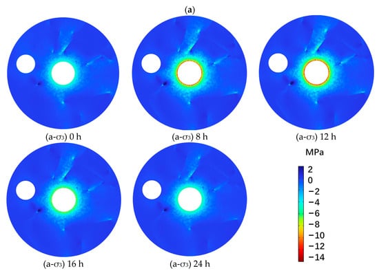
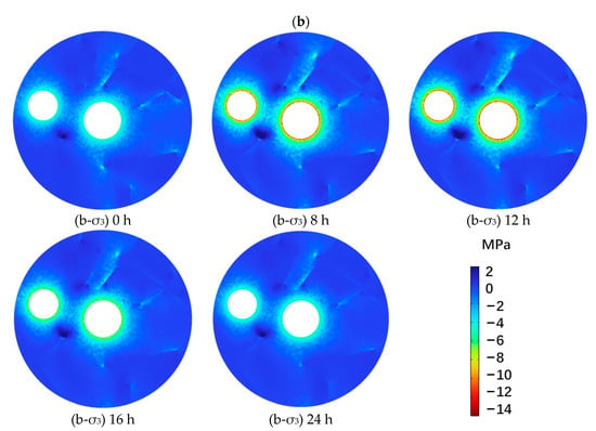
Figure 9.
Contour distribution of third principal stress (σ3) at different times under (a) single-chamber operation and (b) dual-chamber operation.
Under single-chamber operation, compressive stress is primarily localized around Chamber 1, especially at the interface between the lining layer and the surrounding rock. At 0 h, the stress field is uniform and low. As hydrogen injection begins, a sharp compressive ring appears by 8 h and becomes more pronounced at 12 h, with localized peak compression exceeding −12 MPa. Notably, several stress “hot spots” emerge near pre-existing fracture tips, where compression is intensified by stress concentration mechanisms. After the start of the discharge phase (16 h and 24 h), the compressive zones gradually weaken, yet some residual stress remains around fractures, indicating partial inelastic retention in fractured zones.
In the case of dual-chamber operation, the compressive stress fields around both chambers expand rapidly and interact. At 8 h and 12 h, overlapping high-stress regions form between the two chambers, with compression levels reaching up to −14 MPa in the inter-cavity rock bridge. This area also coincides with fracture clusters, suggesting a high potential for fracture activation or shear closure depending on fracture orientation. At 16 h and 24 h, although the peak stress values diminish, compressive stress remains concentrated around fracture intersections and cavity peripheries, reflecting continued rock mass deformation and slower stress relaxation due to inter-cavity confinement.
Importantly, the spatial distribution of σ3 indicates that fractures significantly alter the stress field, acting either as stress relievers or intensifiers depending on their location and geometry. Fractures oriented normal to the stress path tend to accumulate compression and may become sites of closure or dilation, whereas oblique fractures may exhibit shear-enhanced stress zones, especially in the dual-chamber configuration.
4.6. Contour Analysis of Displacement Field
Figure 10 presents the spatial distribution of total displacement under two operational modes: (a) single-chamber operation and (b) dual-chamber operation. The contours illustrate the cumulative deformation of the rock domain due to gas pressurization and reveal how fracture structures modulate the displacement field.
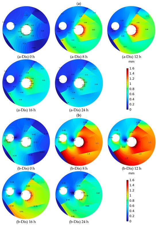
Figure 10.
Contour distribution of total displacement at different times under (a) single-chamber operation and (b) dual-chamber operation.
In the single-chamber case, displacement concentrates around Chamber 1 during the injection phase. At 0 h, the initial deformation is minimal. By 8 h and especially at 12 h, radial displacement increases sharply, peaking around the chamber boundary with maximum values approaching 1.1 mm. The surrounding rock experiences a gradient deformation that extends outward in an elliptical pattern, modulated by fracture distribution. Some fractures deflect the displacement field, causing localized distortions and contour discontinuities. After pressure release (16–24 h), deformation begins to recede, though residual displacement persists, particularly near fracture clusters, suggesting partial inelastic behavior.
Under dual-chamber operation, the displacement field becomes markedly more complex and intense. The highest deformation, exceeding 1.6 mm, occurs at the inner boundaries of both chambers during peak injection (12 h). A broad interaction zone forms between the two cavities, where displacement fields overlap. This superimposed deformation results in asymmetric distortion, especially where fracture networks are aligned between the chambers. The contours in the inter-cavity region show significant curvature and abrupt gradient changes, indicating strong mechanical interference and stress redistribution due to both pressurization and geological heterogeneity.
Fractures play a prominent role in shaping the displacement field in both cases. Areas with high fracture density exhibit enhanced deformation, likely due to reduced stiffness and preferential strain concentration. In the dual-chamber setup, fractures located between the chambers not only accommodate displacement but also act as potential slip planes or deformation amplifiers, which may compromise system integrity under repeated cycling.
5. Conclusions
This study developed a coupled thermo-mechanical model to investigate the transient response of a dual-cavern underground hydrogen storage system under cyclic pressurization conditions. The model integrates non-isothermal gas behavior, mechanical deformation, fracture heterogeneity, and gas permeation effects in multilayered rock–liner–seal systems. Based on numerical simulations conducted under two operating scenarios: single-cavern operation and simultaneous dual-cavern operation. The following key conclusions can be drawn:
- (1)
- The proposed thermodynamic and mechanical coupling model accurately captures hydrogen behavior during cyclic injection and withdrawal. Validation against existing compressed air models and hydrogen-filling experiments confirmed the reliability of the simulation framework in predicting pressure, temperature, stress, and displacement evolutions under non-isothermal conditions.
- (2)
- Dual-chamber operation leads to amplified mechanical responses compared to single-chamber scenarios. The first principal stress, third principal stress, and total displacement are all elevated under synchronized chamber pressurization, especially in the inter-cavity region. This highlights the necessity of accounting for inter-cavern mechanical interaction in multi-cavity storage system design.
- (3)
- Fractures significantly influence the distribution of stress and displacement fields. Stress concentrations were observed around fracture tips and interfaces, which could become potential initiation points for tensile cracking or shear reactivation. Fractures between chambers also acted as deformation amplifiers under dual loading conditions.
- (4)
- While the sealing layer maintains compressive integrity during operation, increased stress and residual displacement under dual-chamber cycling suggest long-term fatigue risk. Design strategies should include optimization of chamber spacing, sealing material selection, and fracture-informed risk assessment to ensure structural stability and gas containment.
Overall, the findings of this study demonstrate the critical role of thermo-mechanical coupling, fracture distribution, and multi-cavern interaction in determining the safety and performance of underground hydrogen storage systems. The validated numerical framework provides a reliable basis for evaluating storage stability under realistic operational conditions. These insights can inform the engineering design and operational strategy of future large-scale hydrogen storage facilities, particularly in complex geological environments. Future work may further incorporate gas diffusion into fractures, long-term fatigue effects, and three-dimensional configurations to enhance model fidelity and applicability. At the same time, we will incorporate fracture evolution criteria, such as slip thresholds or stress-intensity-based propagation rules, to better simulate long-term fracture activation and containment integrity under cyclic pressurization in the future.
Author Contributions
Conceptualization, C.H. and X.L.; methodology, C.H. and B.J.; software, C.H. and L.H.; validation, L.H. and K.Z.; writing—original draft preparation, C.H., B.J. and X.L.; writing—review and editing, B.J., L.H. and K.Z.; funding acquisition, X.L. and K.Z. All authors have read and agreed to the published version of the manuscript.
Funding
This research was funded by the Science and Technology Project of Xuzhou (KC23427) and the Basic Research Program of 423 Jiangsu (BM2022009). This work was led and completed by the research team of compressed air energy storage at Yunlong Lake Laboratory of Deep Underground Science and Engineering.
Data Availability Statement
The original contributions presented in this study are included in the article. Further inquiries can be directed to the corresponding author(s).
Conflicts of Interest
The authors declare no conflicts of interest.
References
- Yue, M.; Lambert, H.; Pahon, E.; Roche, R.; Jemei, S.; Hissel, D. Hydrogen Energy Systems: A Critical Review of Technologies, Applications, Trends and Challenges. Renew. Sustain. Energy Rev. 2021, 146, 111180. [Google Scholar] [CrossRef]
- Ma, N.; Zhao, W.; Wang, W.; Li, X.; Zhou, H. Large Scale of Green Hydrogen Storage: Opportunities and Challenges. Int. J. Hydrogen Energy 2024, 50, 379–396. [Google Scholar] [CrossRef]
- Hu, B.; Yu, L.; Mi, X.; Xu, F.; Li, S.; Li, W.; Wei, C.; Zhang, T. Comparative Analysis of Thermodynamic and Mechanical Responses between Underground Hydrogen Storage and Compressed Air Energy Storage in Lined Rock Caverns. Int. J. Min. Sci. Technol. 2024, 34, 531–543. [Google Scholar] [CrossRef]
- Tarkowski, R.; Uliasz-Misiak, B. Towards Underground Hydrogen Storage: A Review of Barriers. Renew. Sustain. Energy Rev. 2022, 162, 112451. [Google Scholar] [CrossRef]
- Małachowska, A.; Łukasik, N.; Mioduska, J.; Gębicki, J. Hydrogen Storage in Geological Formations—The Potential of Salt Caverns. Energies 2022, 15, 5038. [Google Scholar] [CrossRef]
- Wang, X.; Ma, H.; Liang, W.; Zeng, Z.; Li, H.; Fang, J.; Liang, R. Feasibility Study of Hydrogen Storage in Multi-Interlayered Salt Caverns. Int. J. Hydrogen Energy 2025, 147, 149900. [Google Scholar] [CrossRef]
- Rathnayaka, R.I.A.; Ranjith, P.G. Hydrogen Storage in Unlined Rock Caverns: An Insight on Opportunities and Challenges. Int. J. Hydrogen Energy 2024, 72, 1023–1037. [Google Scholar] [CrossRef]
- Ahad, M.T.; Bhuiyan, M.M.H.; Sakib, A.N.; Becerril Corral, A.; Siddique, Z. An Overview of Challenges for the Future of Hydrogen. Materials 2023, 16, 6680. [Google Scholar] [CrossRef] [PubMed]
- Picard, D.; Dimanov, A.; Raphanel, J.L. Plastic Behavior of Halite Single-Crystals at Different Temperatures and Strain Rates: New Insights from In-Situ Experiments and Full Field Measures. Mater. Sci. Eng. A 2018, 732, 284–297. [Google Scholar] [CrossRef]
- Hu, B.; Mi, X.; Yu, L.; Li, S.; Li, W.; Wei, C. Effects of Cushion Gas Pressure and Operating Parameters on the Capacity of Hydrogen Storage in Lined Rock Caverns (LRC). Renew. Energy 2024, 235, 121317. [Google Scholar] [CrossRef]
- Li, H.; Cao, X.; Liu, Y.; Shao, Y.; Nan, Z.; Teng, L.; Peng, W.; Bian, J. Safety of Hydrogen Storage and Transportation: An Overview on Mechanisms, Techniques, and Challenges. Energy Rep. 2022, 8, 6258–6269. [Google Scholar] [CrossRef]
- Bo, Z.; Hörning, S.; Underschultz, J.R.; Garnett, A.; Hurter, S. Effects of Geological Heterogeneity on Gas Mixing during Underground Hydrogen Storage (UHS) in Braided-Fluvial Reservoirs. Fuel 2024, 357, 129949. [Google Scholar] [CrossRef]
- Seshagiri Rao, K. Characterization, Modelling and Engineering of Rocks and Rockmasses. Indian Geotech. J. 2020, 50, 1–95. [Google Scholar] [CrossRef]
- Brantut, N.; Petit, L. Micromechanics of Rock Damage and Its Recovery in Cyclic Loading Conditions. Geophys. J. Int. 2023, 233, 145–161. [Google Scholar] [CrossRef]
- Wang, H.; Zhang, B.; Yu, X.; Xu, N.; Ye, J. Long-Term Stability and Deformation Behaviour of Anhydrite Mine-out for Crude Oil Storage. Rock Mech. Rock Eng. 2020, 53, 1719–1735. [Google Scholar] [CrossRef]
- Zhan, J.; Pang, Y.; Chen, J.; Cao, C.; Song, S.; Zhou, X. A Progressive Framework for Delineating Homogeneous Domains in Complicated Fractured Rock Masses: A Case Study from the Xulong Dam Site, China. Rock Mech. Rock Eng. 2020, 53, 1623–1646. [Google Scholar] [CrossRef]
- Patanwar, Y.K.; Kim, H.-M.; Deb, D.; Gujjala, Y.K. Underground Storage of Hydrogen in Lined Rock Caverns: An Overview of Key Components and Hydrogen Embrittlement Challenges. Int. J. Hydrogen Energy 2024, 50, 116–133. [Google Scholar] [CrossRef]
- Zhao, C.; Lei, Q.; Zhang, Z. Impact of Fracture Networks on the Structural Deformation of Lined Rock Caverns under High Internal Gas Pressure. Undergr. Space 2025, 21, 252–269. [Google Scholar] [CrossRef]
- Sun, R.; Wang, J. Effects of In Situ Stress and Multiborehole Cluster on Hydraulic Fracturing of Shale Gas Reservoir from Multiscale Perspective. J. Energy Eng. 2024, 150, 04024002. [Google Scholar] [CrossRef]
- Hu, C.; Li, X.; Hu, L.; Jia, B.; He, L.; Zhang, K.; Ji, Y.; Zhao, P. Thermodynamic Analysis of Hydrogen Storage in Lined Rock Cavern with Different Sealing Layer Materials and Thicknesses. Processes 2025, 13, 1665. [Google Scholar] [CrossRef]
- Qiu, K.; Li, S.; Wang, Z.; Wan, Z.; Zhao, S. Research on Influence Patterns of Fault Activation on Lining Structures in Lined Rock Caverns for Underground Hydrogen Energy Storage. Int. J. Hydrogen Energy 2024, 58, 605–620. [Google Scholar] [CrossRef]
- Li, P.; Kang, H.; Zhu, Q.; Wu, Y.; Zhang, J.; Fan, L.; Wang, Z. Numerical and Experimental Investigations of Concrete Lined Compressed Air Energy Storage System. J. Clean. Prod. 2023, 390, 136153. [Google Scholar] [CrossRef]
- Fan, Y.; Wang, X.; Liu, Y.; Liu, Z.; Xi, G.; Shangguan, L. Study on the Effect of Salt Solution on Durability of Basalt-Fiber-Reinforced Polymer Joints in High-Temperature Environment. Polymers 2022, 14, 2250. [Google Scholar] [CrossRef] [PubMed]
- Nirmal, U.; Teo, J.J.; Chin, C.W.; Yousif, B.F. Review on Erosion Wear Subjected to Different Coating Materials on Leading Edge Protection for Cooling Towers and Wind Turbines. J. Bio-Tribo-Corros. 2025, 11, 20. [Google Scholar] [CrossRef]
- Li, F.; Li, F.; Sun, R.; Zheng, J.; Li, X.; Shen, L.; Sun, Q.; Liu, Y.; Ji, Y.; Duan, Y. A Study on the Transient Response of Compressed Air Energy Storage in the Interaction between Gas Storage Chambers and Horseshoe-Shaped Tunnels in an Abandoned Coal Mine. Energies 2024, 17, 953. [Google Scholar] [CrossRef]
- Wang, M.; Shi, A.-C.; Li, H.-B.; Yan, H.-C.; Fan, G.; Zhou, J.-W. Mechanism Analysis of Surrounding Rock Mass Failure Induced by the Multi-Cavern Effect in a Large-Scale Underground Powerhouse. Appl. Sci. 2023, 13, 4376. [Google Scholar] [CrossRef]
- Ji, W.; Wang, S.; Wan, J.; Cheng, S.; He, J.; Shi, S. Stability Analysis of Surrounding Rock of Multi-Cavern for Compressed Air Energy Storage. Adv. Geo-Energy Res. 2024, 13, 169–175. [Google Scholar] [CrossRef]
- Ramesh Kumar, K.; Honorio, H.; Chandra, D.; Lesueur, M.; Hajibeygi, H. Comprehensive Review of Geomechanics of Underground Hydrogen Storage in Depleted Reservoirs and Salt Caverns. J. Energy Storage 2023, 73, 108912. [Google Scholar] [CrossRef]
- Ramesh Kumar, K.; Makhmutov, A.; Spiers, C.J.; Hajibeygi, H. Geomechanical Simulation of Energy Storage in Salt Formations. Sci. Rep. 2021, 11, 19640. [Google Scholar] [CrossRef] [PubMed]
- Zhang, J.; Fan, Y.; Liu, W.; Liu, H.; Xu, B. In Situ Stress Evolution and Fault-Slip Tendency Assessment of an Underground Gas Storage Reservoir in the Turpan Basin (China): In Situ Stress Measurements and Coupled Simulations. Rock Mech. Rock Eng. 2023, 56, 8019–8039. [Google Scholar] [CrossRef]
- Zhang, G.; Zhu, S.; Zeng, D.; Jia, Y.; Mi, L.; Yang, X.; Zhang, J. Sealing Capacity Evaluation of Underground Gas Storage under Intricate Geological Conditions. Energy Geosci. 2024, 5, 100292. [Google Scholar] [CrossRef]
- Li, W.; Zhu, C.; Han, J.; Yang, C. Thermodynamic Response of Gas Injection-and-Withdrawal Process in Salt Cavern for Underground Gas Storage. Appl. Therm. Eng. 2019, 163, 114380. [Google Scholar] [CrossRef]
- Vilarrasa, V.; Rutqvist, J. Thermal Effects on Geologic Carbon Storage. Earth-Sci. Rev. 2017, 165, 245–256. [Google Scholar] [CrossRef]
- Bazdar, E.; Sameti, M.; Nasiri, F.; Haghighat, F. Compressed Air Energy Storage in Integrated Energy Systems: A Review. Renew. Sustain. Energy Rev. 2022, 167, 112701. [Google Scholar] [CrossRef]
- Zhou, S.; Xia, C.; Zhou, Y. Long-Term Stability of a Lined Rock Cavern for Compressed Air Energy Storage: Thermo-Mechanical Damage Modeling. Eur. J. Environ. Civ. Eng. 2020, 24, 2070–2093. [Google Scholar] [CrossRef]
- George, S.C.; Thomas, S. Transport Phenomena through Polymeric Systems. Prog. Polym. Sci. 2001, 26, 985–1017. [Google Scholar] [CrossRef]
- Kushnir, R.; Dayan, A.; Ullmann, A. Temperature and Pressure Variations within Compressed Air Energy Storage Caverns. Int. J. Heat Mass Transf. 2012, 55, 5616–5630. [Google Scholar] [CrossRef]
- Wu, D.; Wang, J.G.; Hu, B.; Yang, S.-Q. A Coupled Thermo-Hydro-Mechanical Model for Evaluating Air Leakage from an Unlined Compressed Air Energy Storage Cavern. Renew. Energy 2020, 146, 907–920. [Google Scholar] [CrossRef]
- Li, H.; Ding, R.; Su, W.; Lin, X.; Guan, S.; Ye, Q.; Zheng, Z.; Wang, J. A Comprehensive Performance Comparison between Compressed Air Energy Storage and Compressed Carbon Dioxide Energy Storage. Energy Convers. Manag. 2024, 319, 118972. [Google Scholar] [CrossRef]
- Xu, Y.; Zhou, S.; Xia, C.; Zhao, H.; Xue, X. Three-Dimensional Thermo-Mechanical Analysis of Abandoned Mine Drifts for Underground Compressed Air Energy Storage: A Comparative Study of Two Construction and Plugging Schemes. J. Energy Storage 2021, 39, 102696. [Google Scholar] [CrossRef]
- Fan, X.; Li, C.; Wang, M.; Liu, Y.; Feng, Y.; Liu, Y.; Zhong, X.; Xu, G.; Zhang, Y.; Zheng, Y.; et al. Effects of Adding Different Proportions of H2 to the Simulated Hydrogen-Rich Blast Furnace. Chem. Eng. Technol. 2022, 45, 2284–2291. [Google Scholar] [CrossRef]
- Looney, C.P.; Hagan, Z.M.; Connolly, M.J.; Bradley, P.E.; Slifka, A.J.; Amaro, R.L. Modelling the Test Methods Used to Determine Material Compatibility for Hydrogen Pressure Vessel Service. Int. J. Fatigue 2020, 132, 105339. [Google Scholar] [CrossRef] [PubMed]
- Souza Debossam, J.G.; de Souza, G.; Amaral Souto, H.P.; Pires, A.P. Numerical Simulation of Single-Phase Two-Component Non-Darcy Flow in Naturally Fractured Reservoirs for Enhanced Gas Recovery and Carbon Dioxide Storage. Braz. J. Chem. Eng. 2024, 41, 197–219. [Google Scholar] [CrossRef]
- Yang, J.; Wang, J.G.; Liang, W.; Li, P.; Sun, R. Optimal Selection of Working Fluid for Enhanced Geothermal Systems: A Comparative Analysis of Supercritical Carbon Dioxide and Water under Various Reservoir and Extraction Conditions. Appl. Therm. Eng. 2024, 246, 122947. [Google Scholar] [CrossRef]
- Sun, R.; Wang, J.; Zhang, K.; Li, F.; Ding, X.; Guo, Q. Stress Redistribution in a Multilayer Chamber for Compressed Air Energy Storage in Abandoned Coalmine: Elastic Analytical Insights and Material Choice. Energy Sci. Eng. 2023, 11, 4198–4223. [Google Scholar] [CrossRef]
- Chen, X.; Wang, J.G. Stability Analysis for Compressed Air Energy Storage Cavern with Initial Excavation Damage Zone in an Abandoned Mining Tunnel. J. Energy Storage 2022, 45, 103725. [Google Scholar] [CrossRef]
- Sun, R.; Wang, J.; Zhou, Y.; Shang, X.; Leung, C. Stability Analysis of Compressed Air Energy Storage Cavern Transformed from Horseshoe Shape Roadway in an Abandoned Coal Mine. Deep Undergr. Sci. Eng. 2025. [Google Scholar] [CrossRef]
- Kim, H.-M.; Rutqvist, J.; Ryu, D.-W.; Choi, B.-H.; Sunwoo, C.; Song, W.-K. Exploring the Concept of Compressed Air Energy Storage (CAES) in Lined Rock Caverns at Shallow Depth: A Modeling Study of Air Tightness and Energy Balance. Appl. Energy 2012, 92, 653–667. [Google Scholar] [CrossRef]
- Li, M.; Yang, Q.; Zhang, C.; Huang, S.; Zhang, M.; Zhang, G.; Zhao, L.; Jiang, S. Experimental and Numerical Study of the Temperature Evolution in Hydrogen Cylinder under Fast-Refueling Process. Int. J. Heat Mass Transfer 2023, 211, 124220. [Google Scholar] [CrossRef]
Disclaimer/Publisher’s Note: The statements, opinions and data contained in all publications are solely those of the individual author(s) and contributor(s) and not of MDPI and/or the editor(s). MDPI and/or the editor(s) disclaim responsibility for any injury to people or property resulting from any ideas, methods, instructions or products referred to in the content. |
© 2025 by the authors. Licensee MDPI, Basel, Switzerland. This article is an open access article distributed under the terms and conditions of the Creative Commons Attribution (CC BY) license (https://creativecommons.org/licenses/by/4.0/).