
Computational and Experimental Investigation of Additively Manufactured Lattice Heat Sinks for Liquid-Cooling Railway Power Electronics †


Abstract
1. Introduction
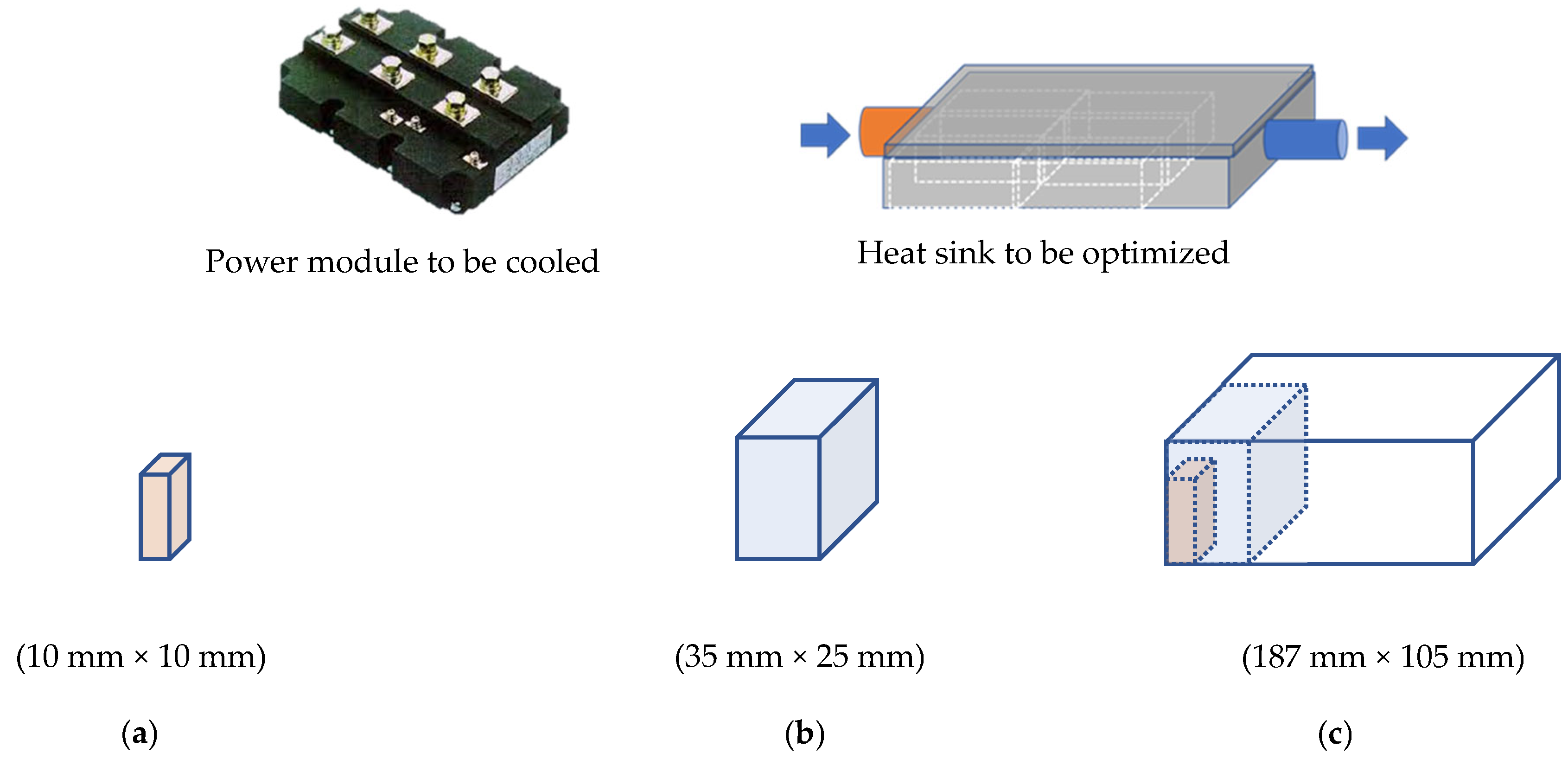
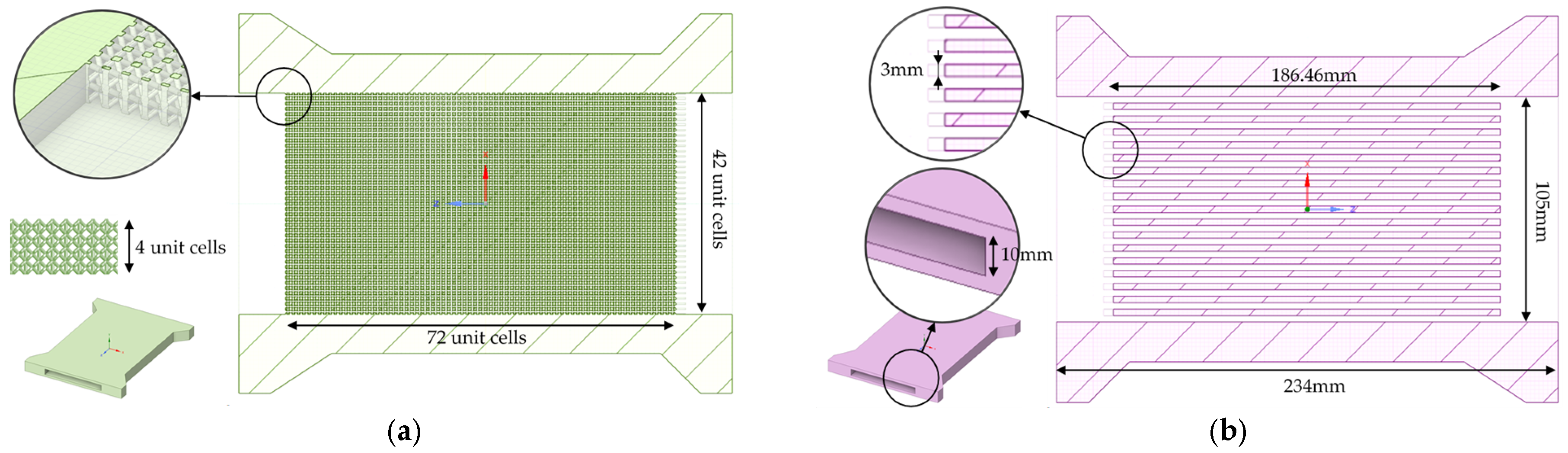
- Evaluating Lattice Topologies: Initial investigations focused on the thermal and hydraulic performance of various LS topologies using a simplified elementary structure (ES) heat sink (Figure 1a) to identify the most efficient topology for further analysis.
- Detailed Computer Fluid Dynamics (CFD) and Experimental Studies: The selected topology, a BCCz LS, is subjected to extensive CFD simulations and experimental validation. The investigations involve testing a reduced structure (RS) heat sink (Figure 1b) under varying flow rates and inlet temperatures. Comparative performance analyses with conventional straight-fin heat sinks are conducted based on metrics such as thermal resistance, pressure drop, and temperature distribution. Geometrical modification effects on performance were evaluated.
- Full Scale Demonstrator (FSD): The final phase involved designing and manufacturing a FSD heat sink (Figure 1c) using the optimized lattice configurations identified earlier. Its performance is benchmarked against conventional straight-fin demonstrator on a real power module.
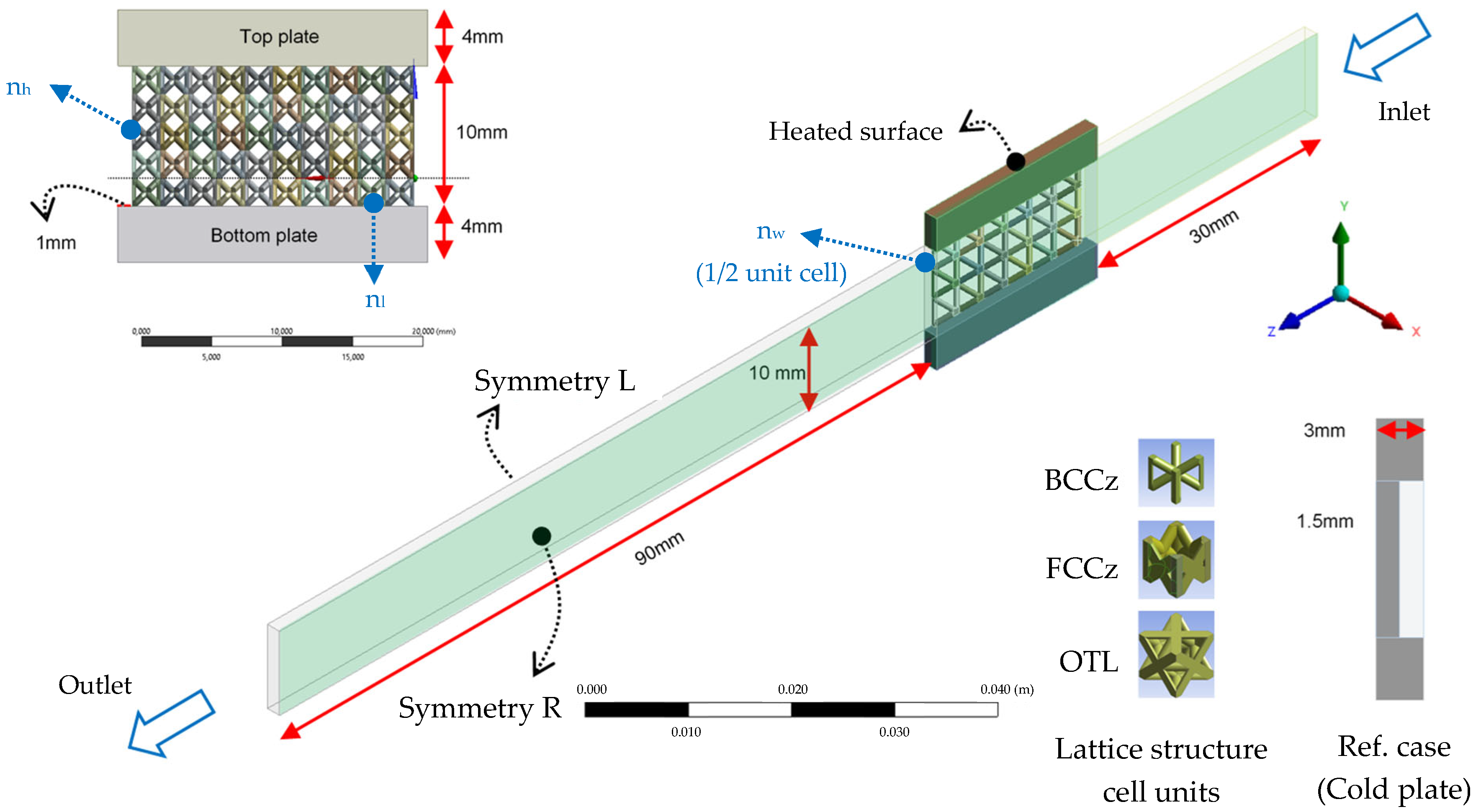
2. Initial Investigation of the Lattice Structure Topologies
3. Experimental and Computational Study on BCCz LS-Based Reduced Structure
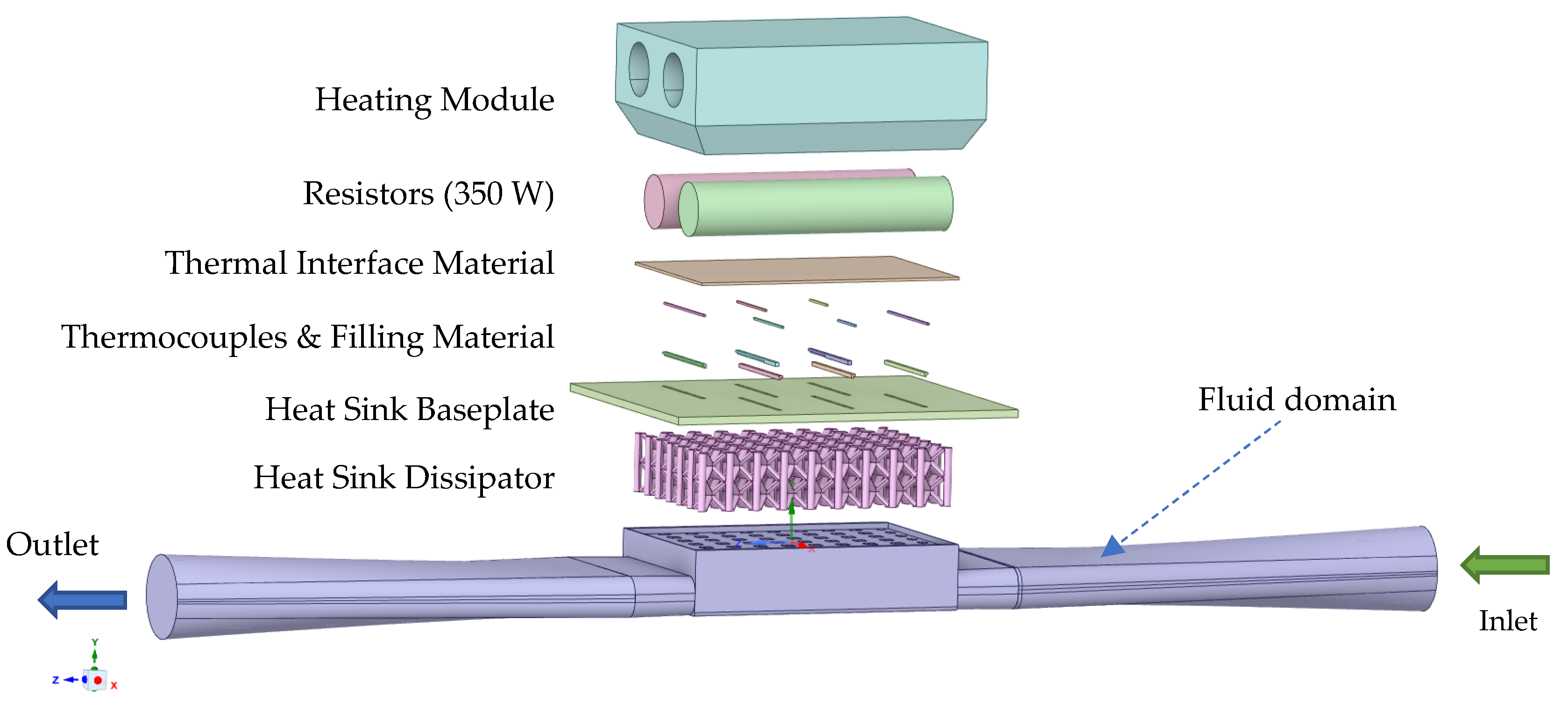
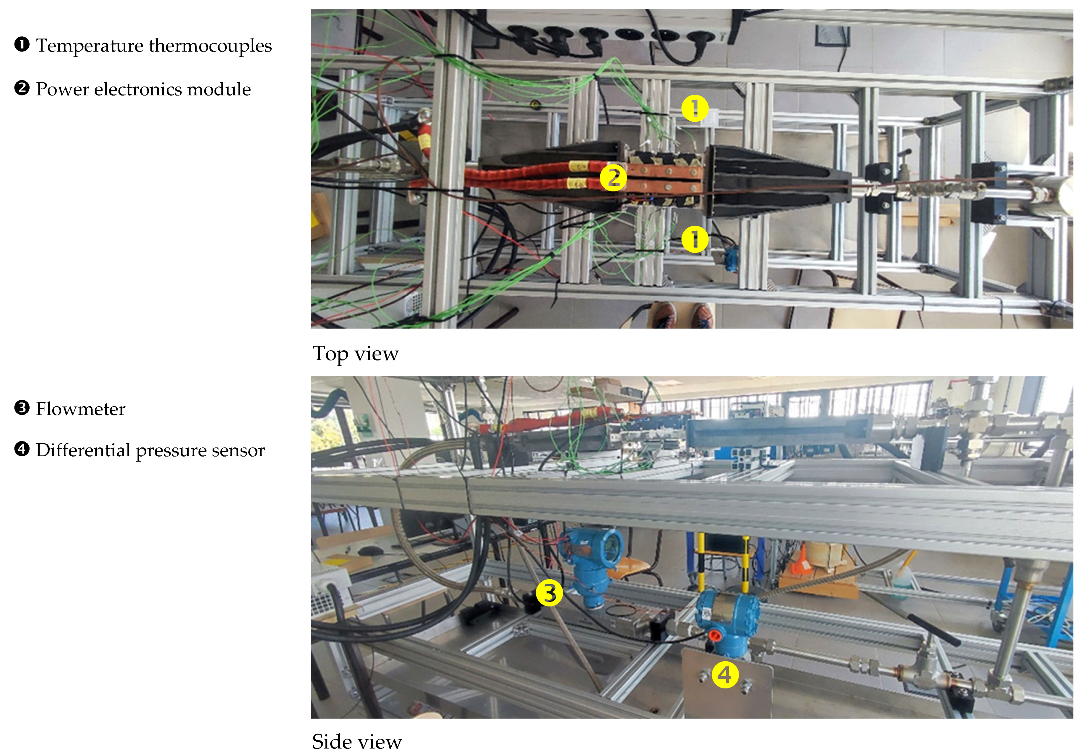
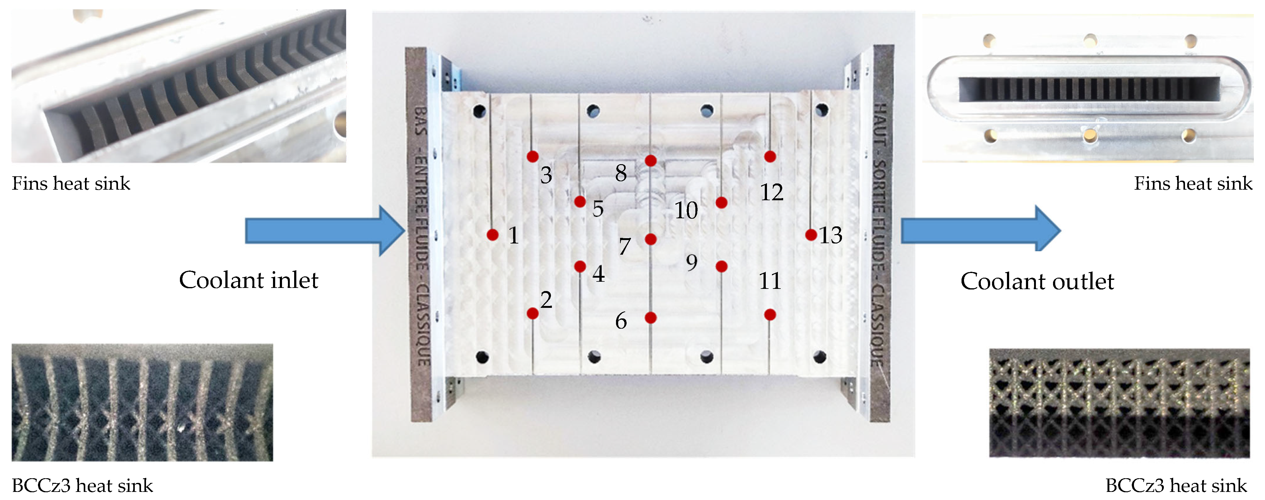
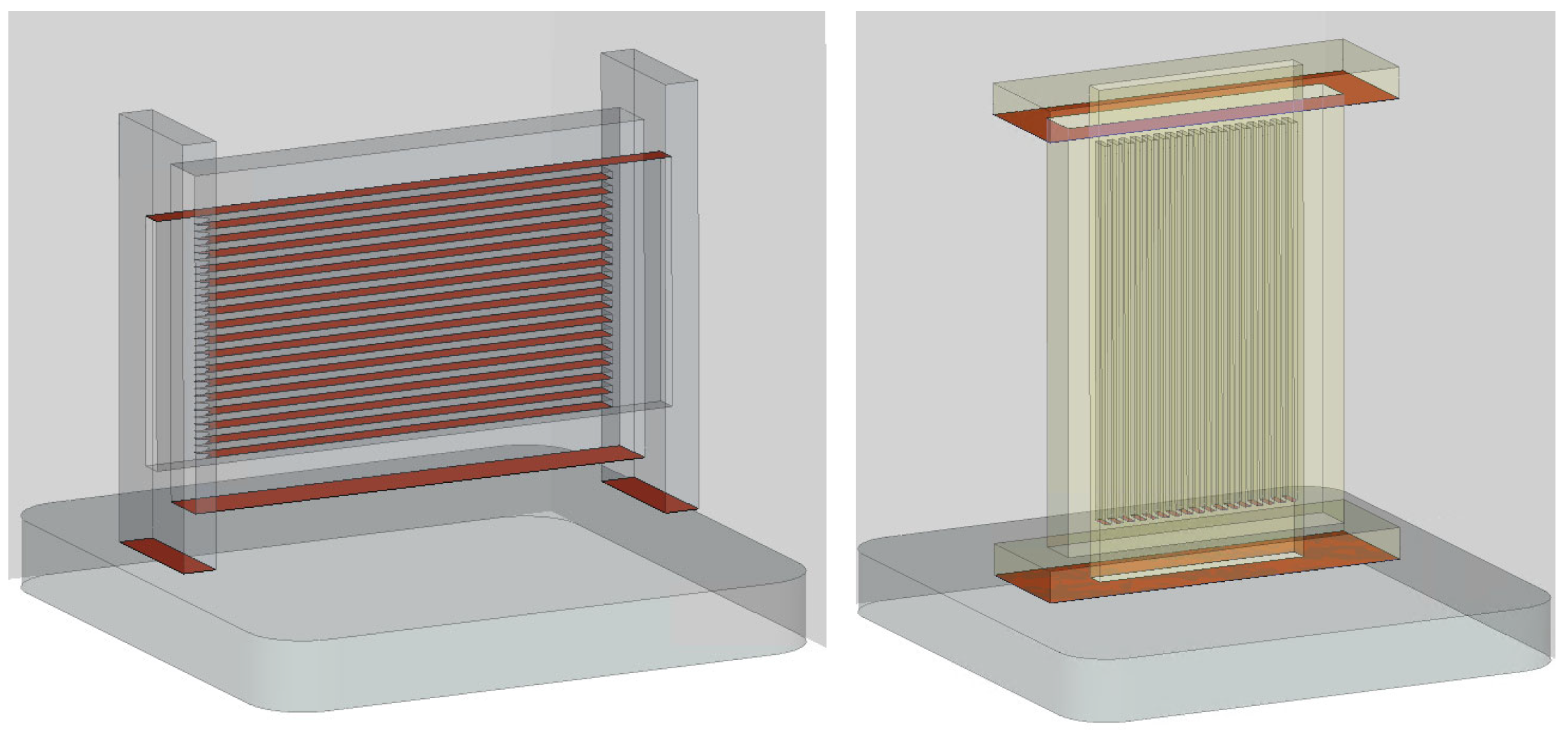
3.1. Reduced Structure Test Bench Design
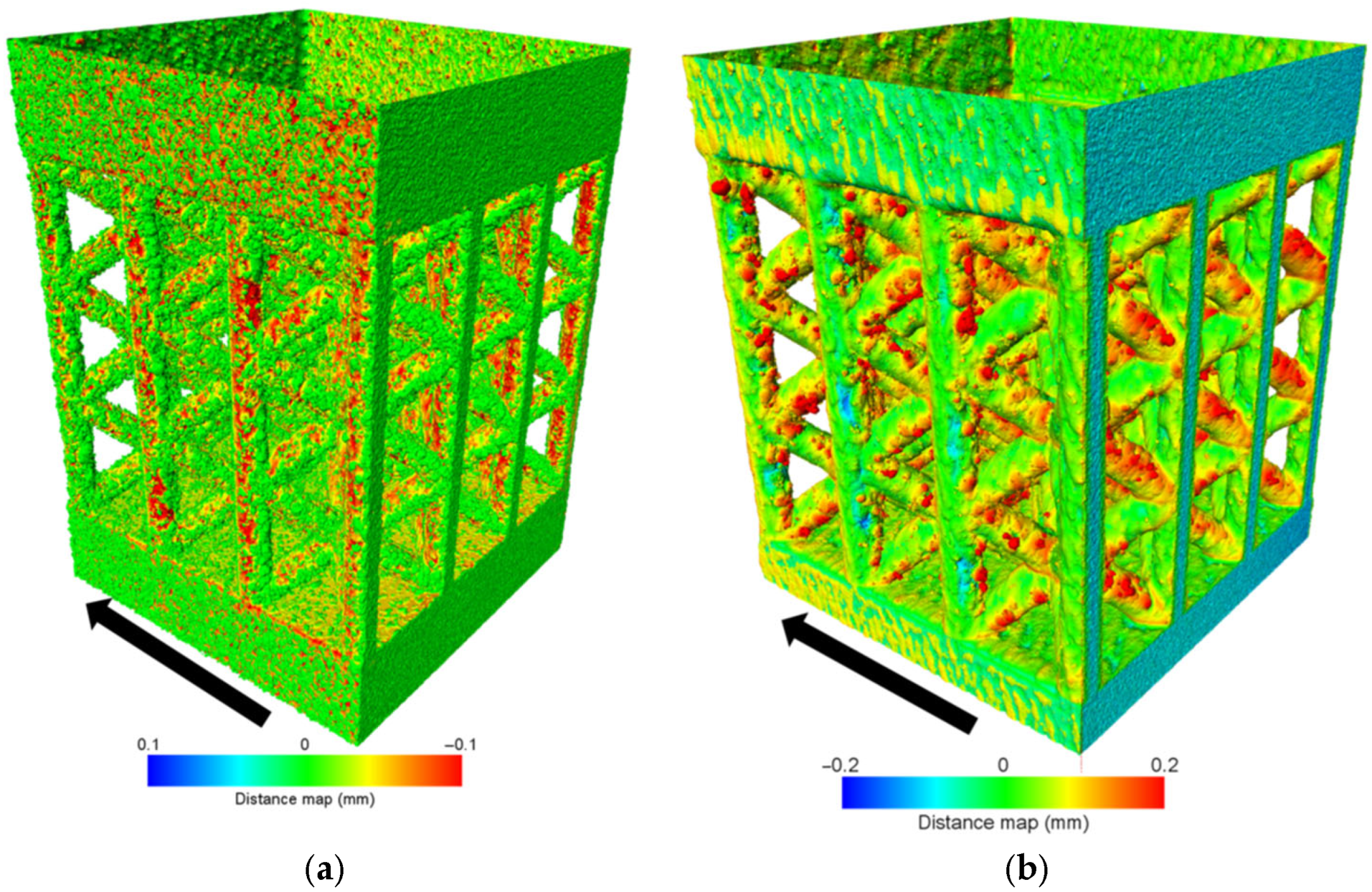
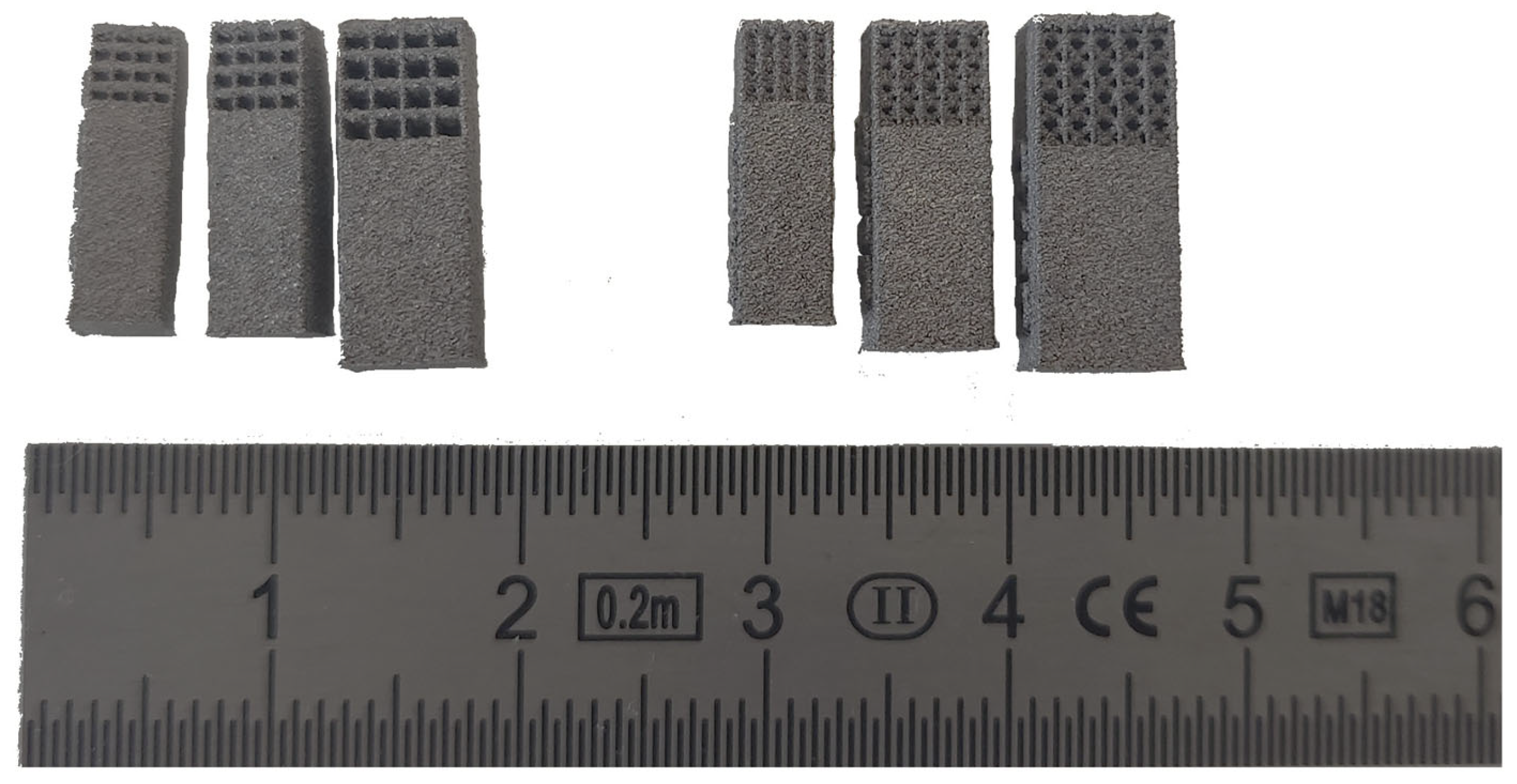
3.2. Reduced Structure Additive Manufacturing
3.2.1. Alloy and Additive Manufacturing Technology
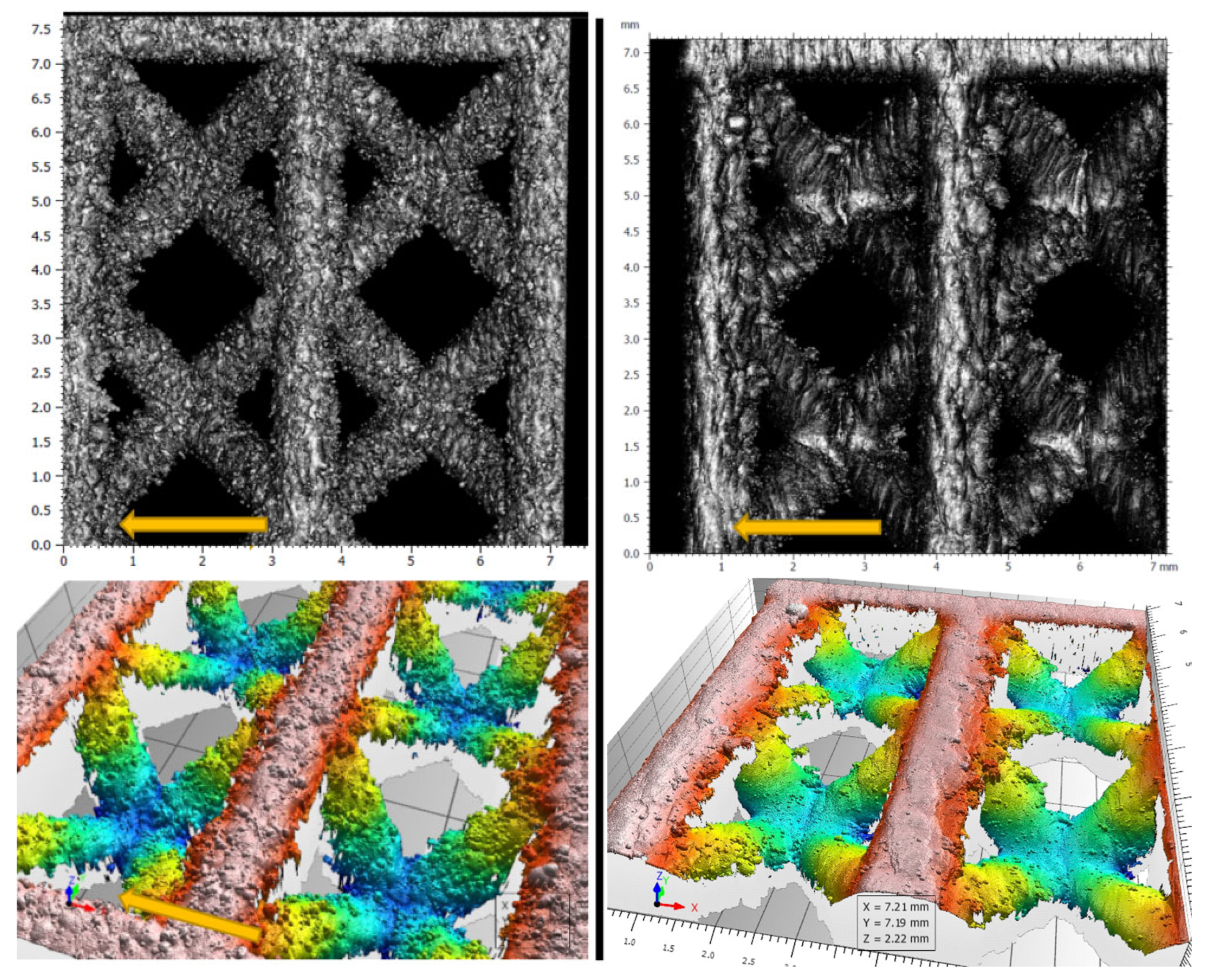
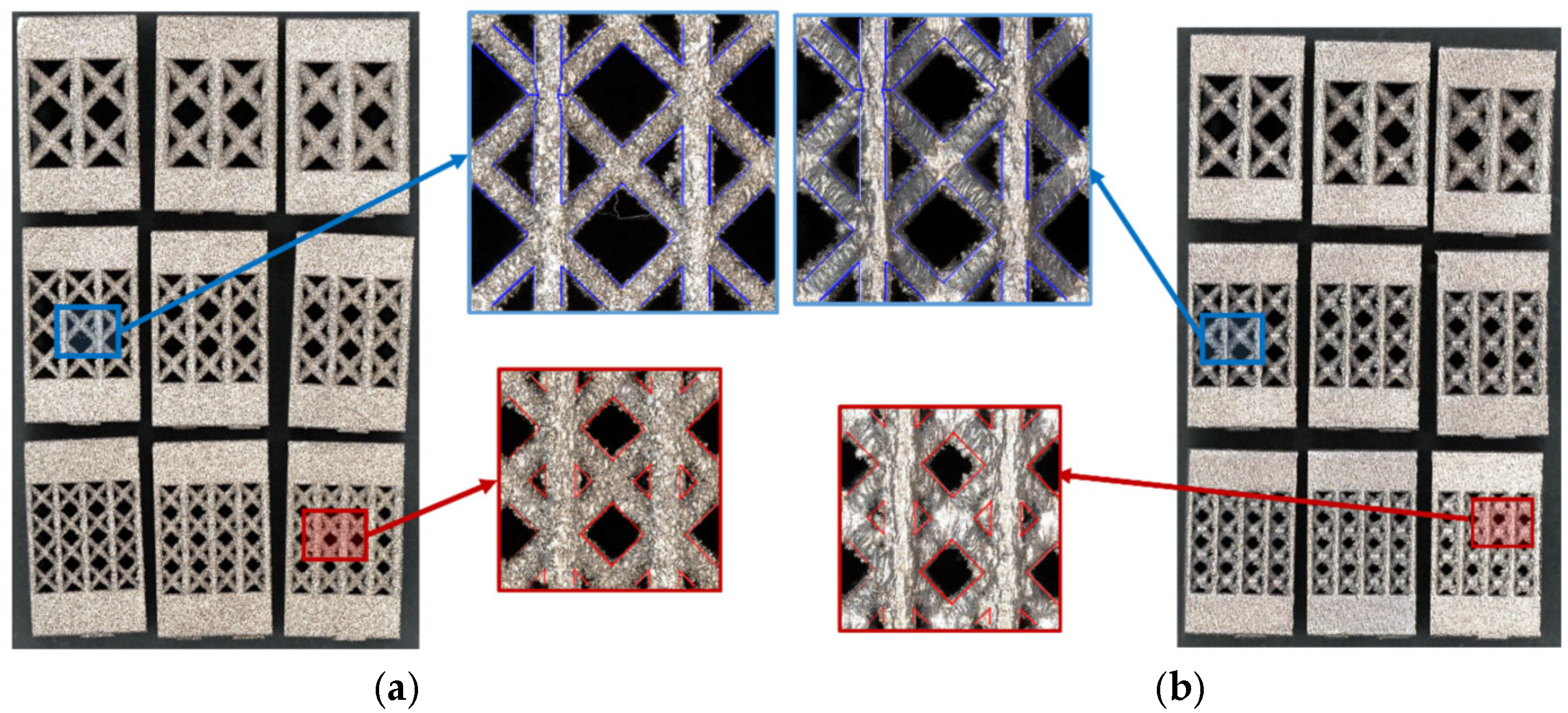
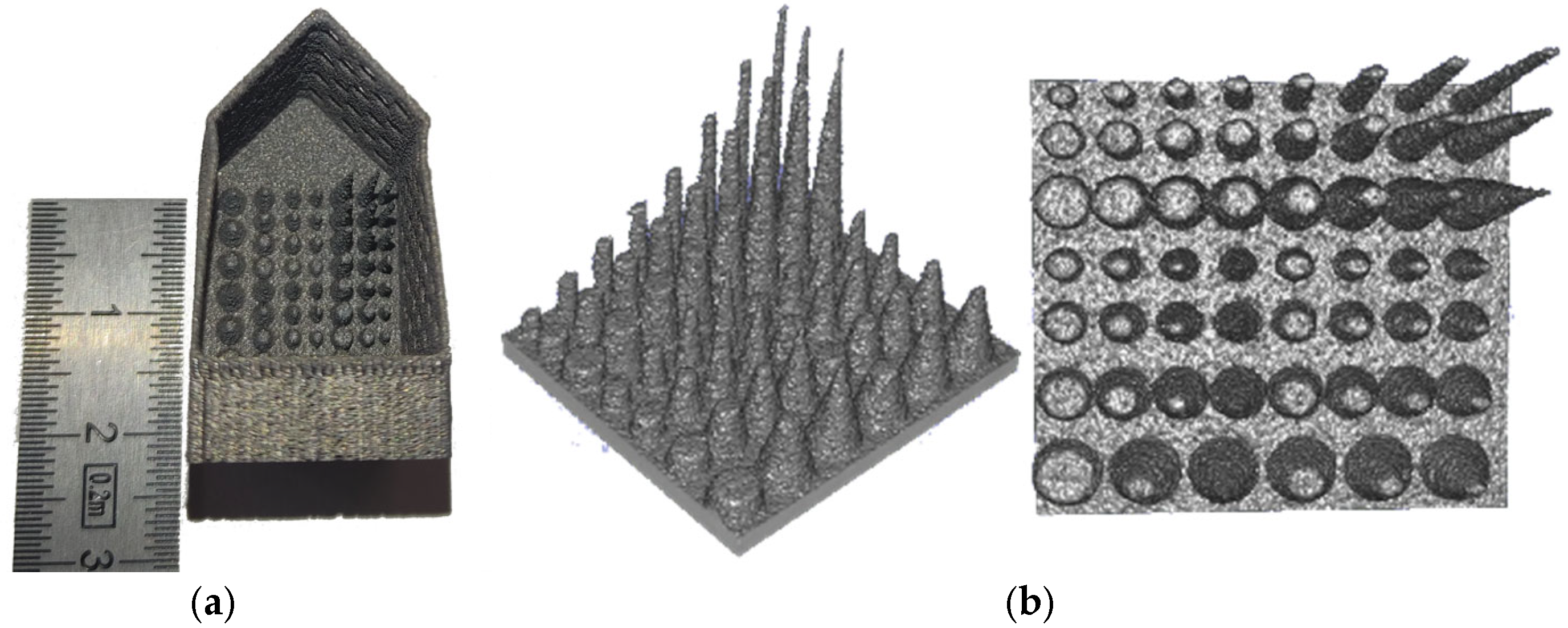
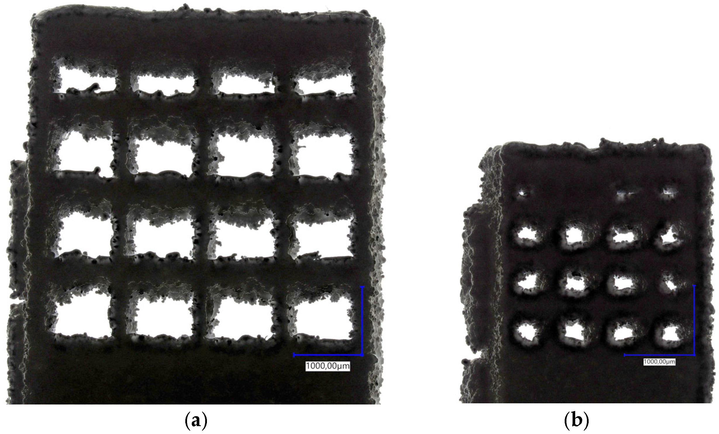
3.2.2. Feasibility Study
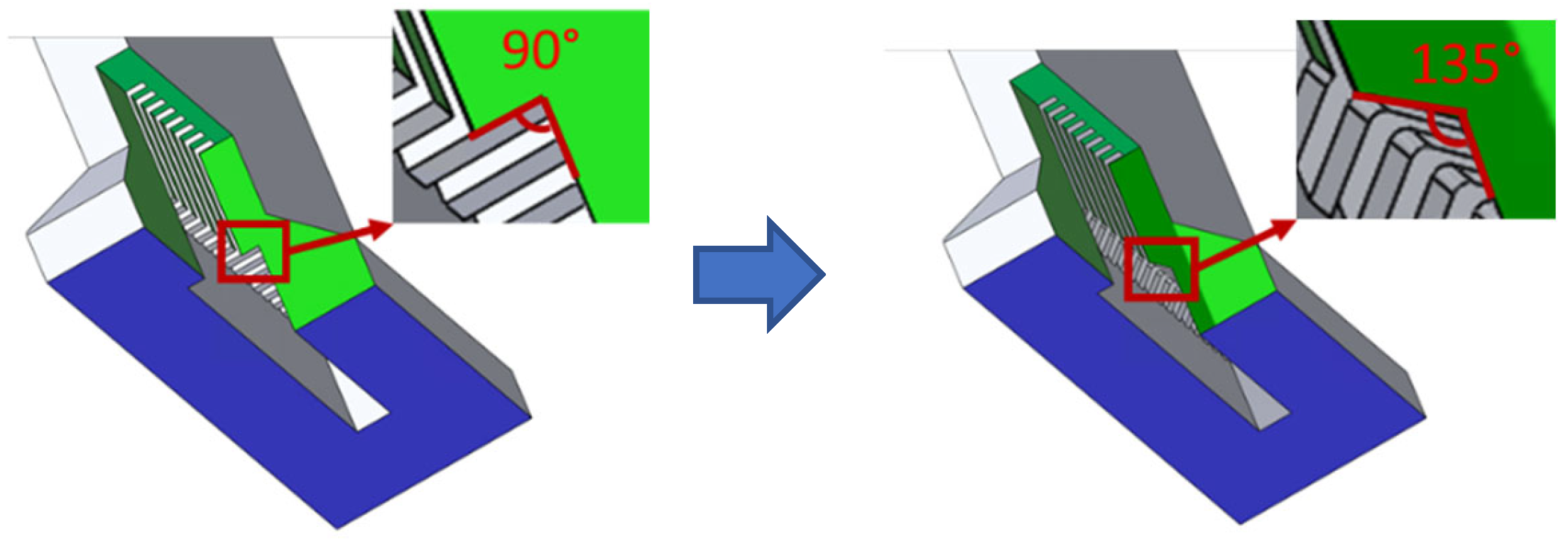
3.2.3. Further Design Limits Explorations
3.2.4. Corrosion Behavior
3.3. Computational Configuration
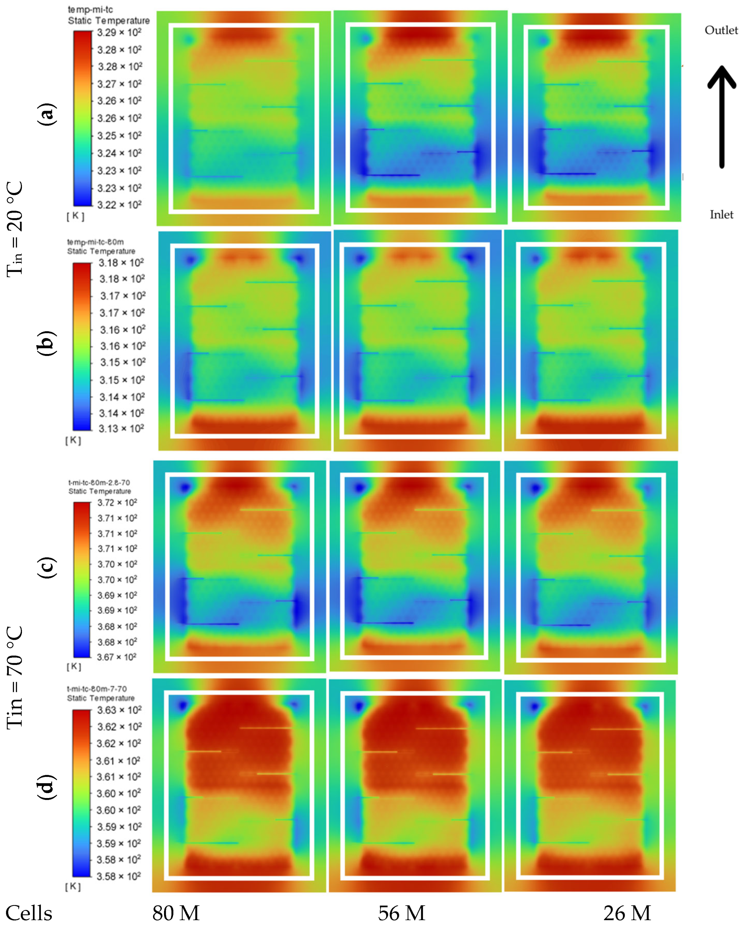
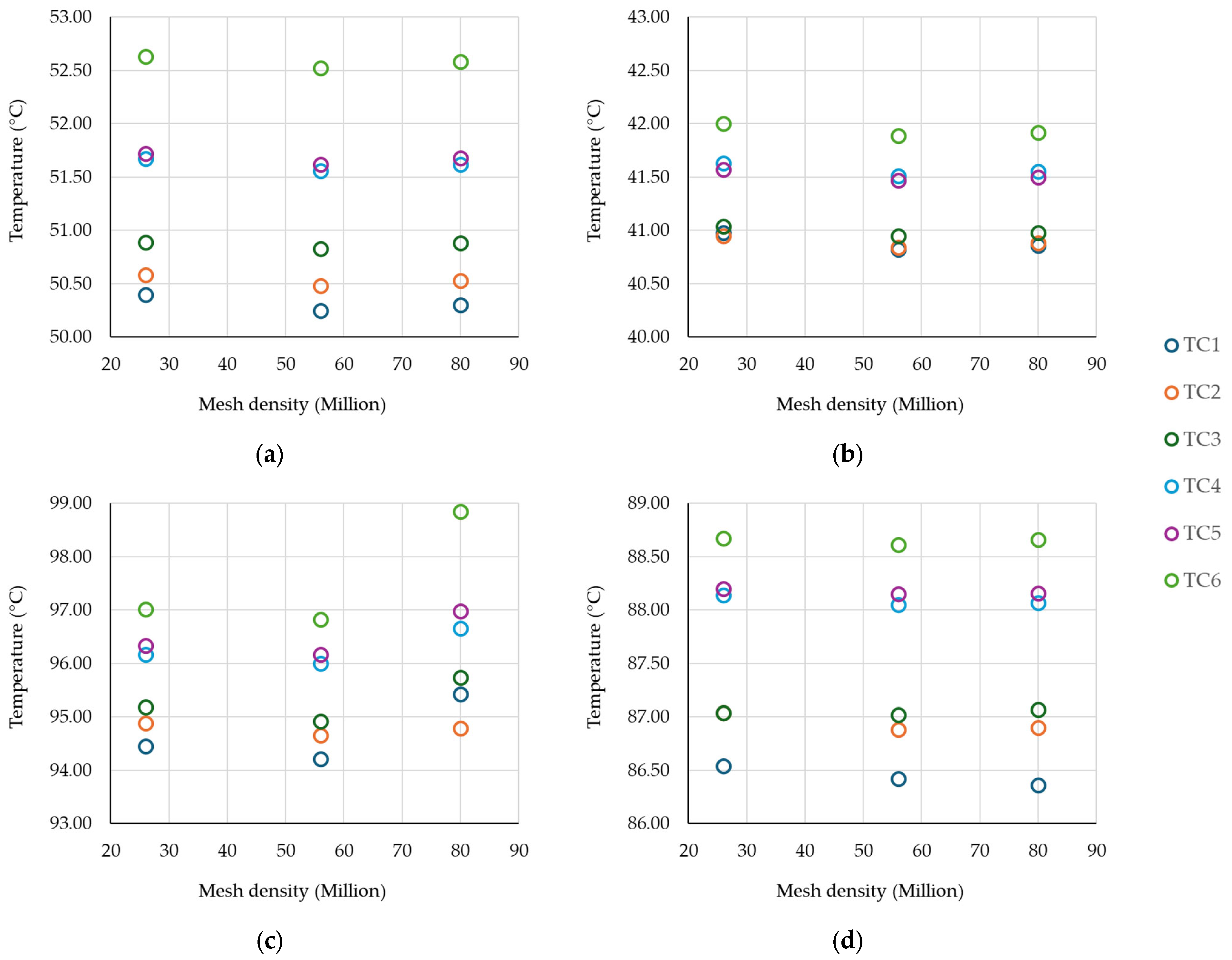
3.4. Reduced Structure—Results and Discussion
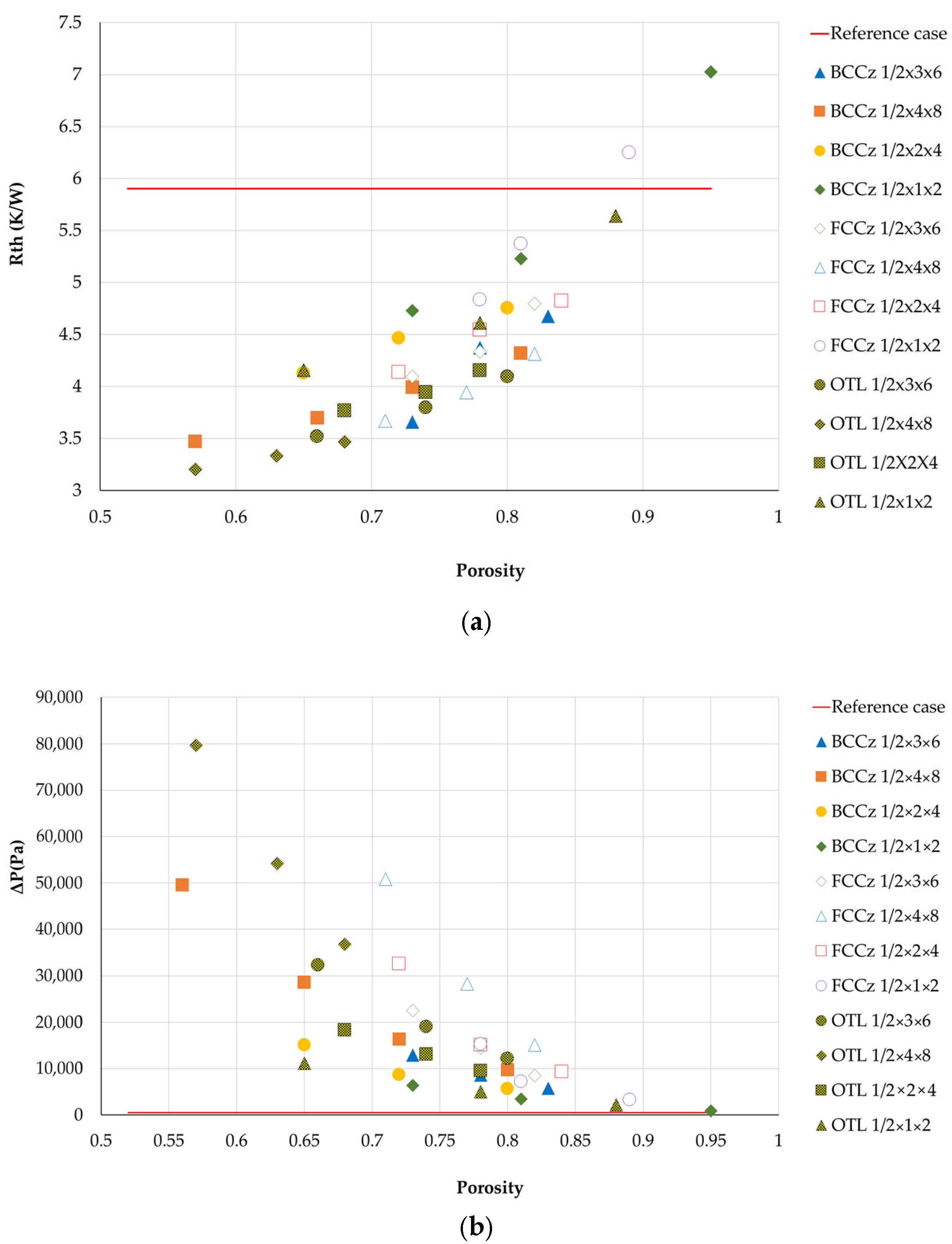
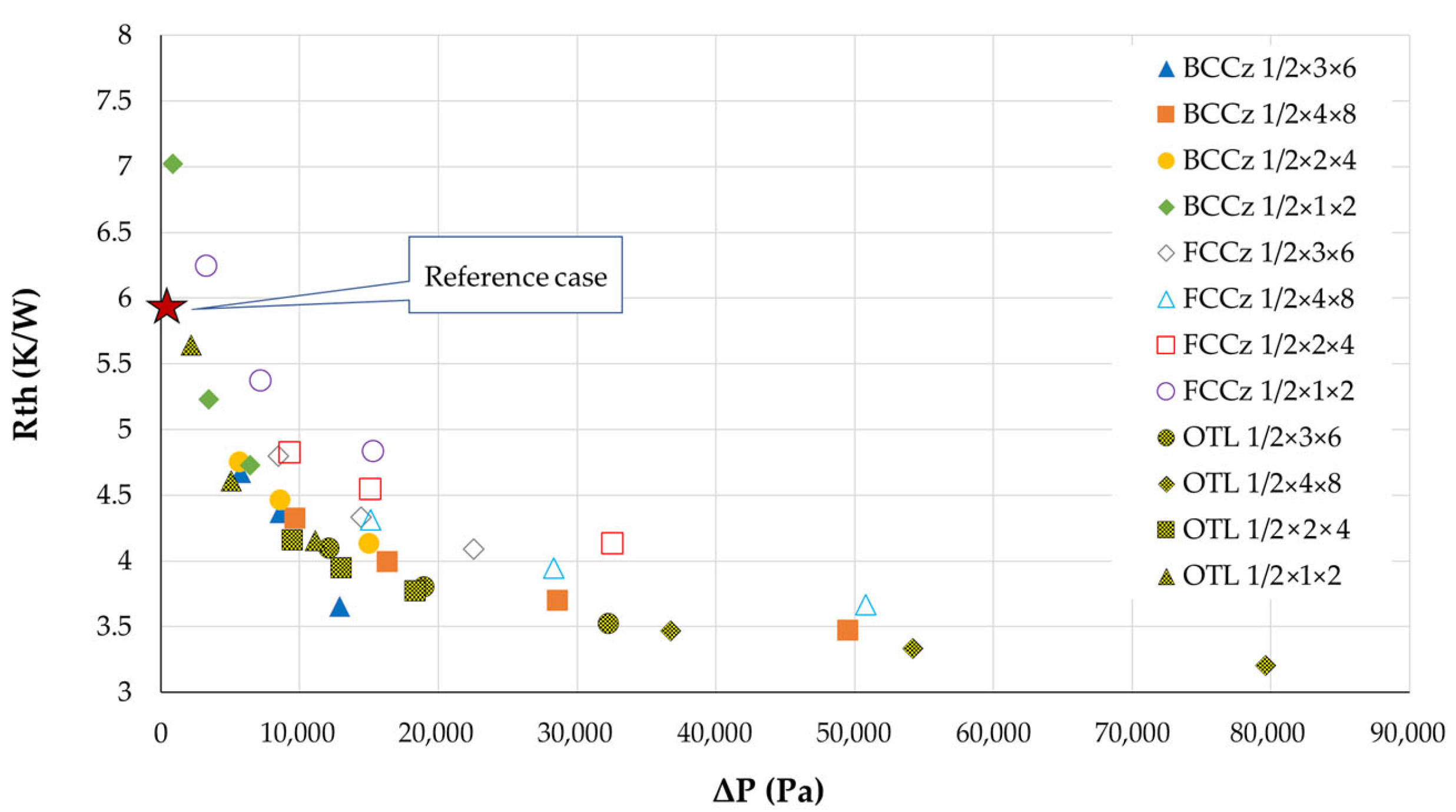
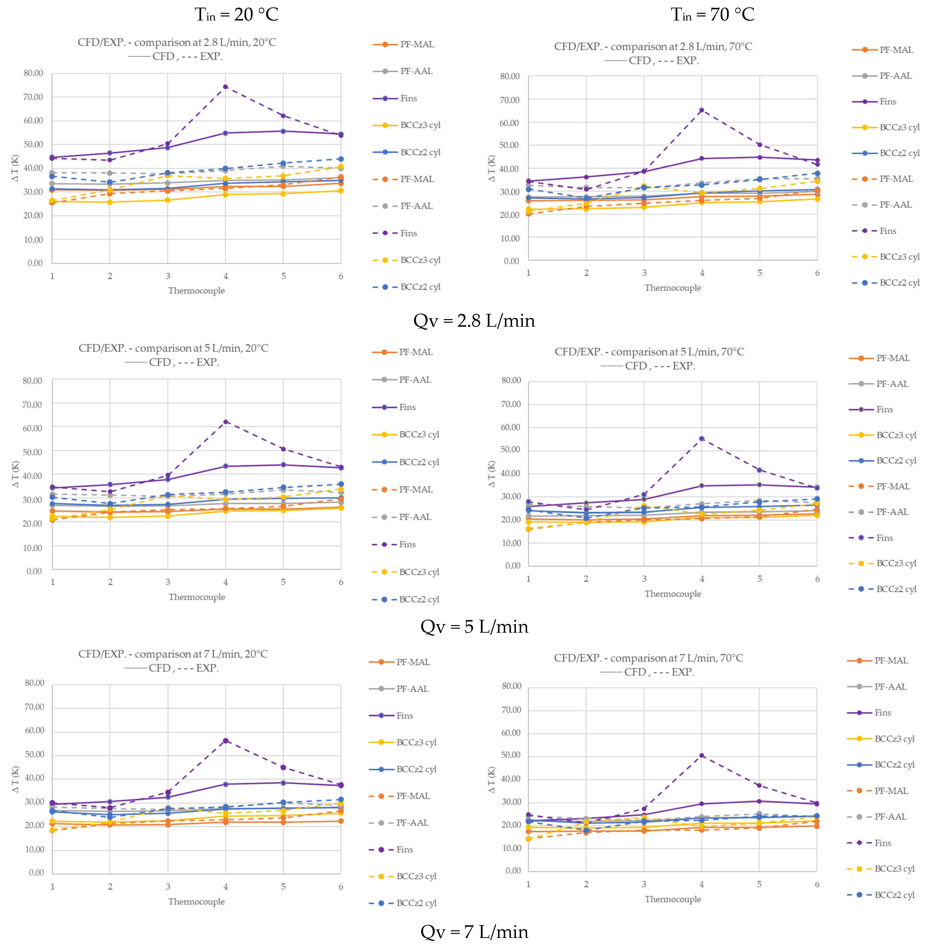
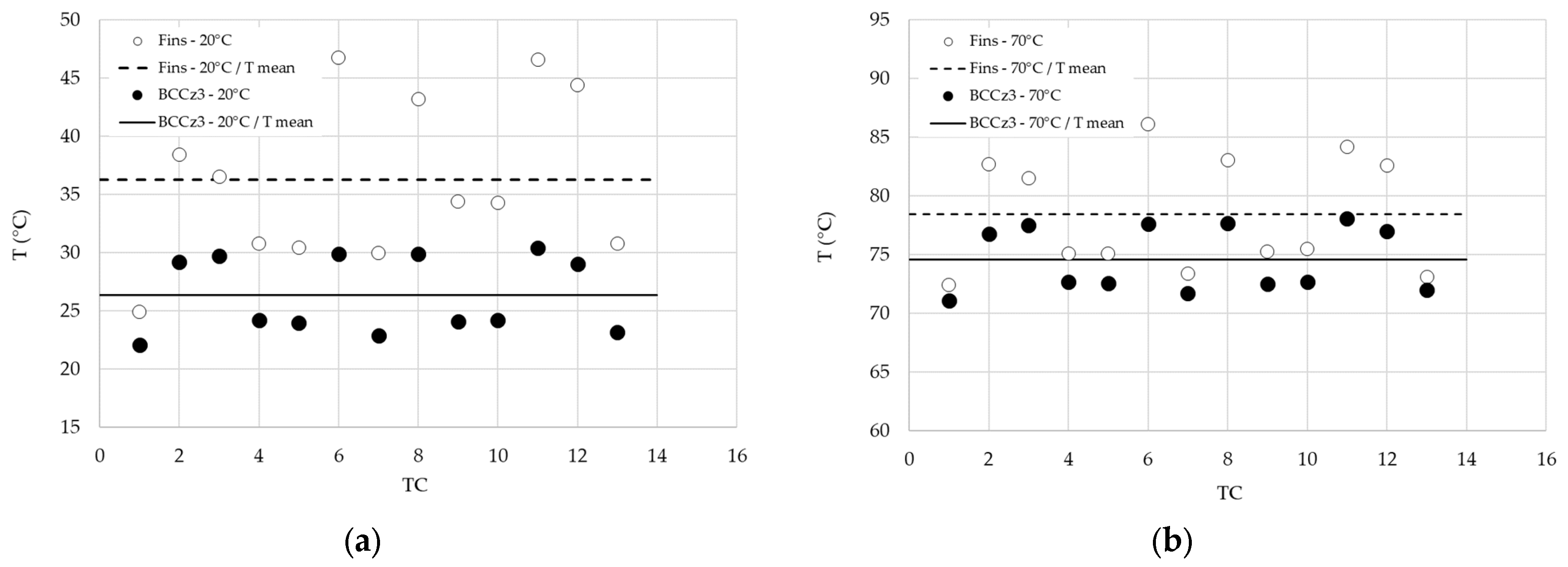
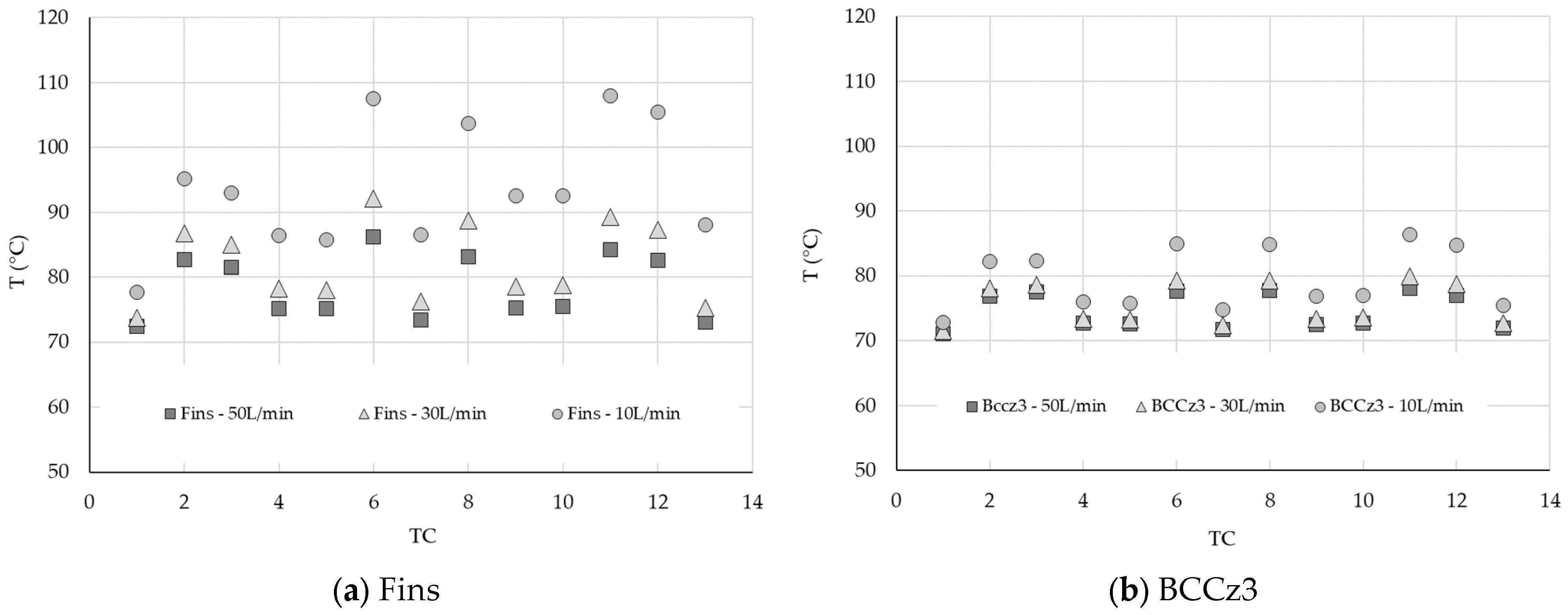
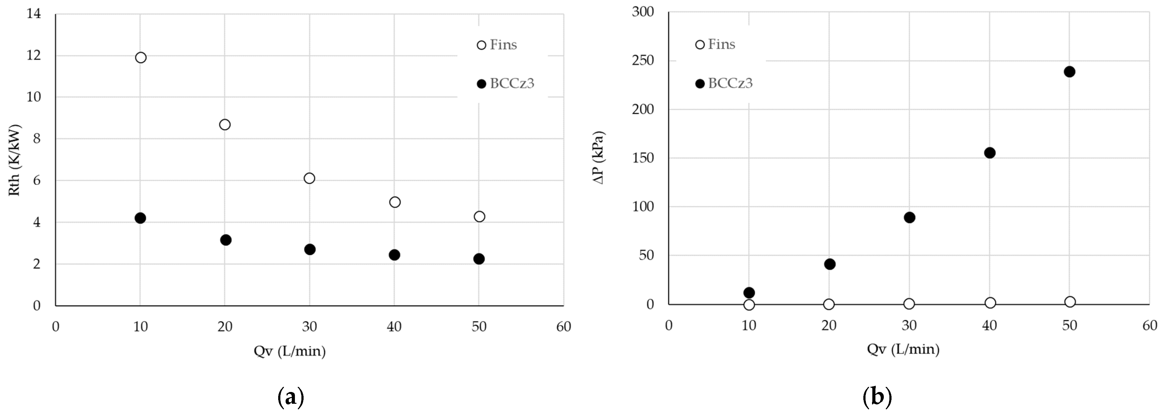
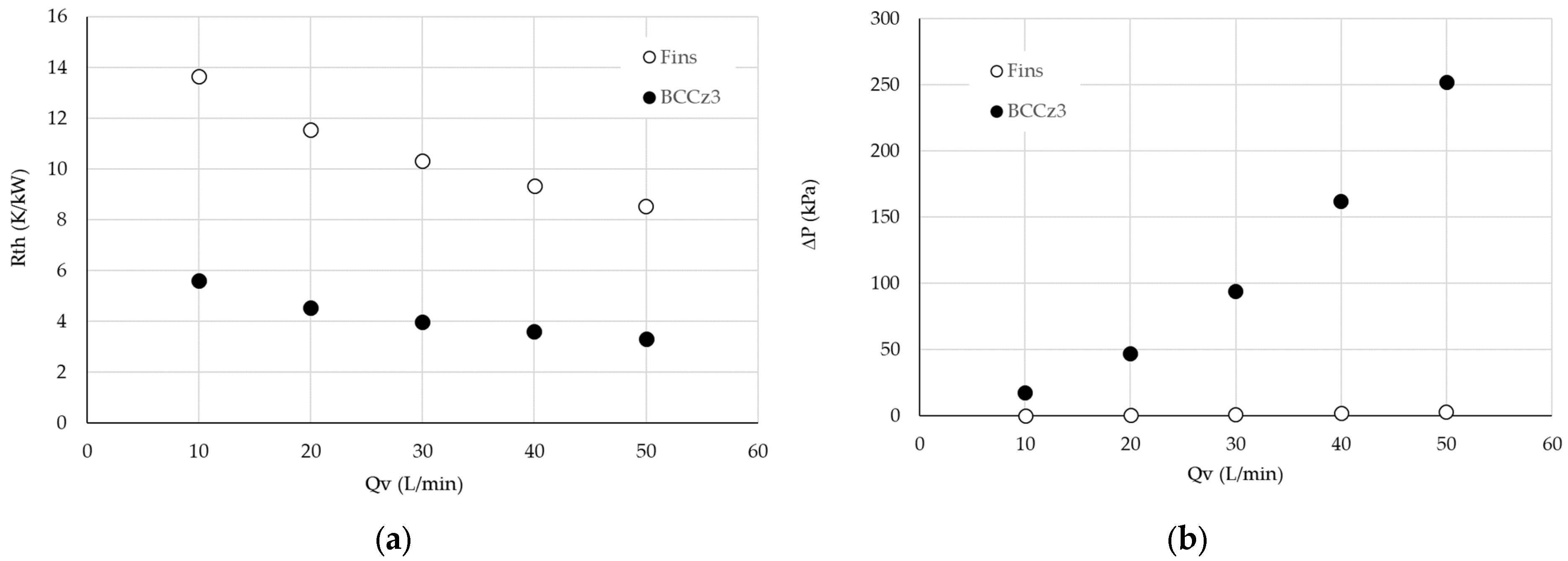
3.4.1. Comparison of Conventional Heat Sink and LS Heat Sinks
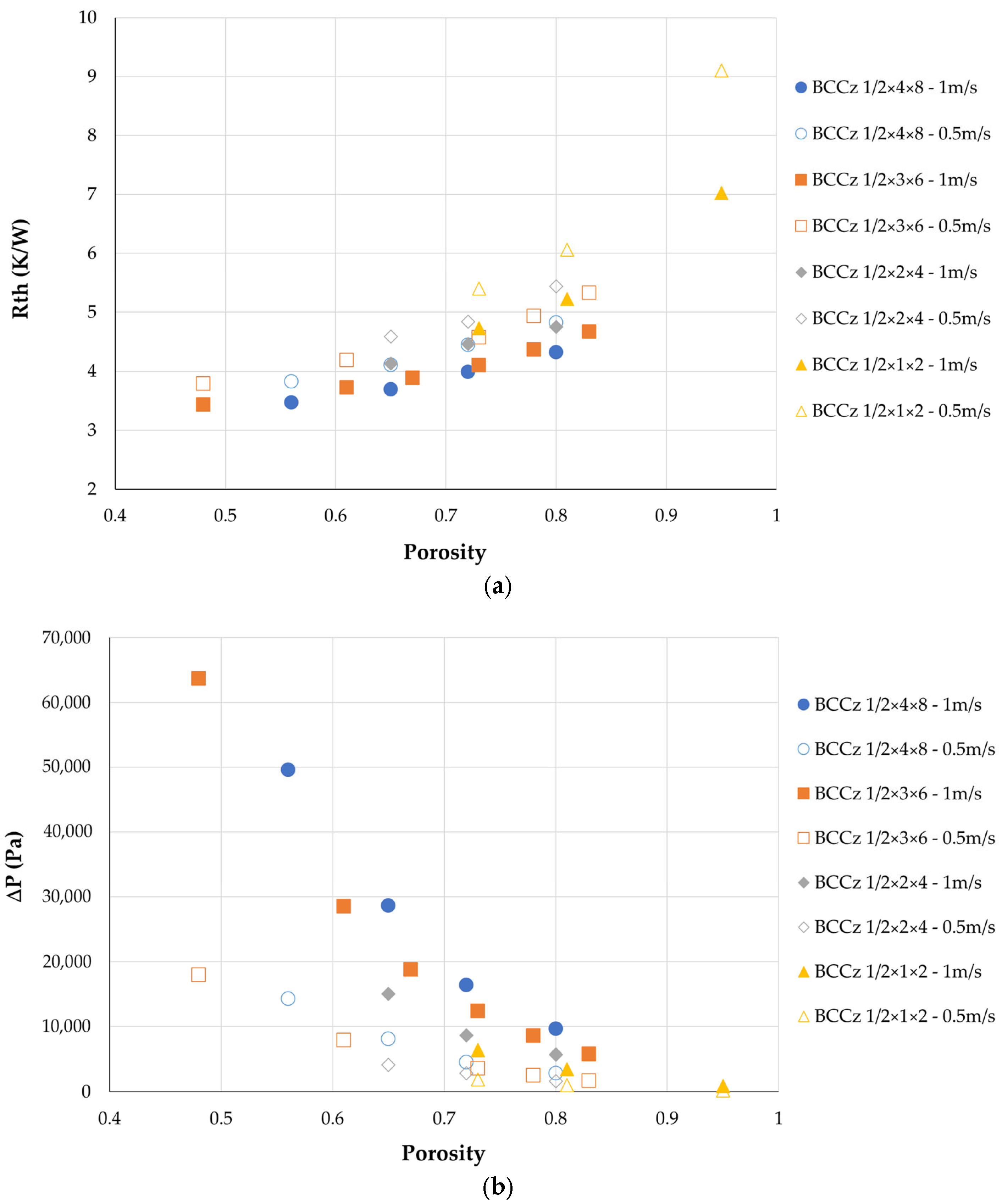
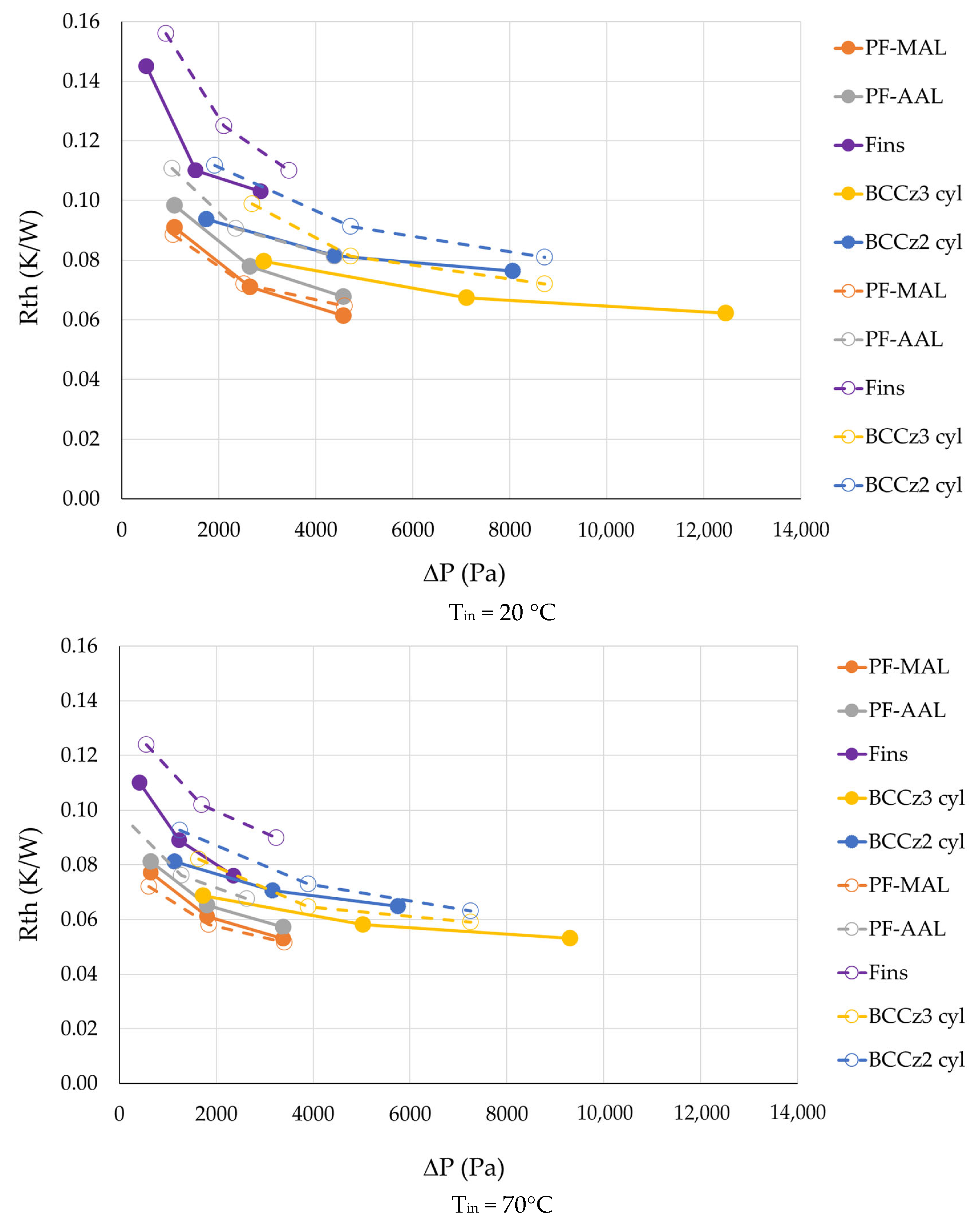
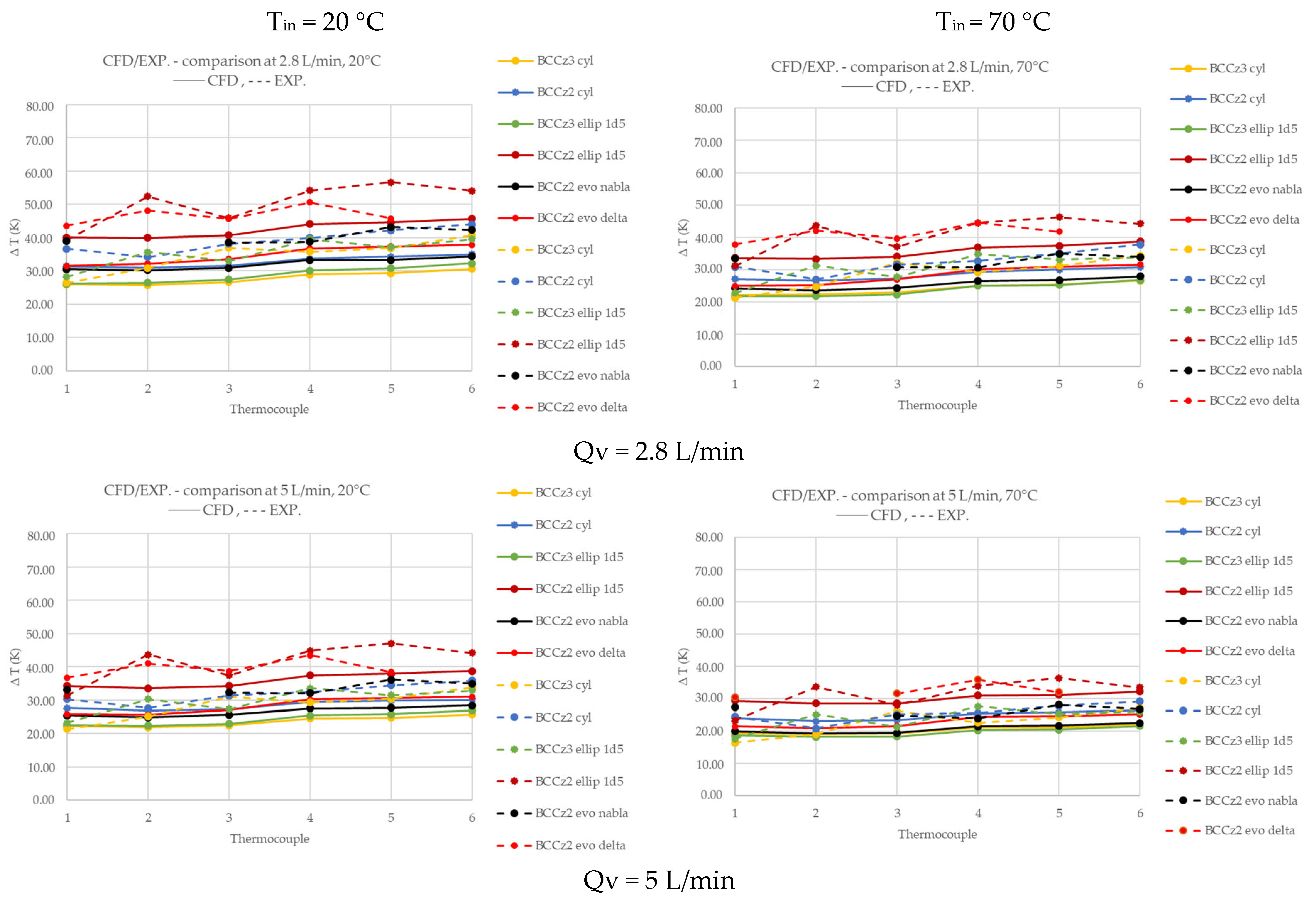
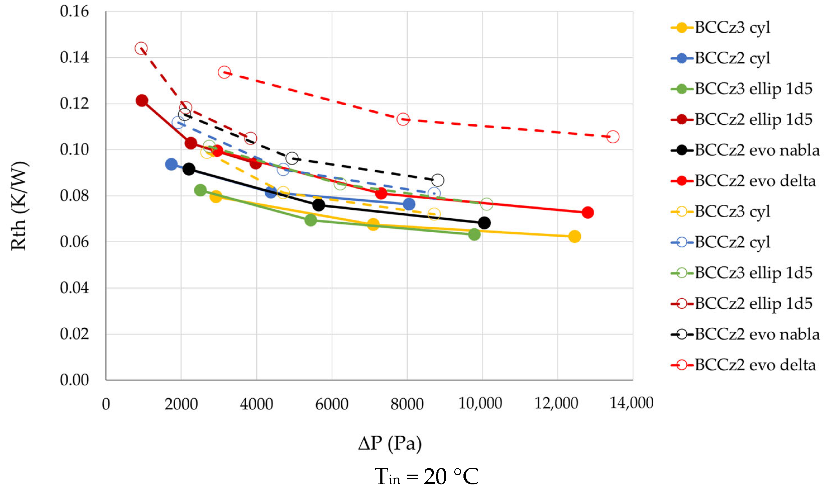
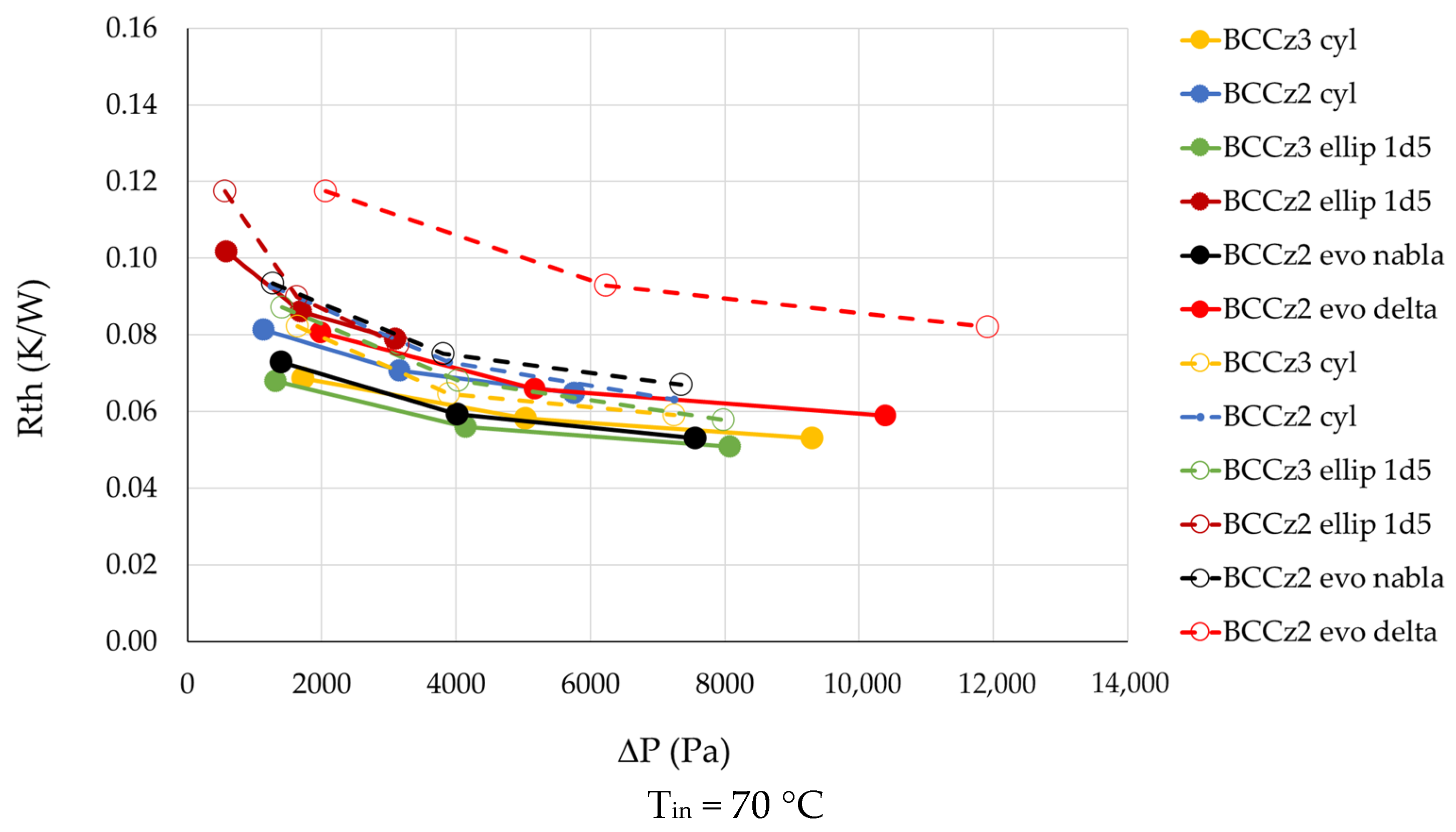
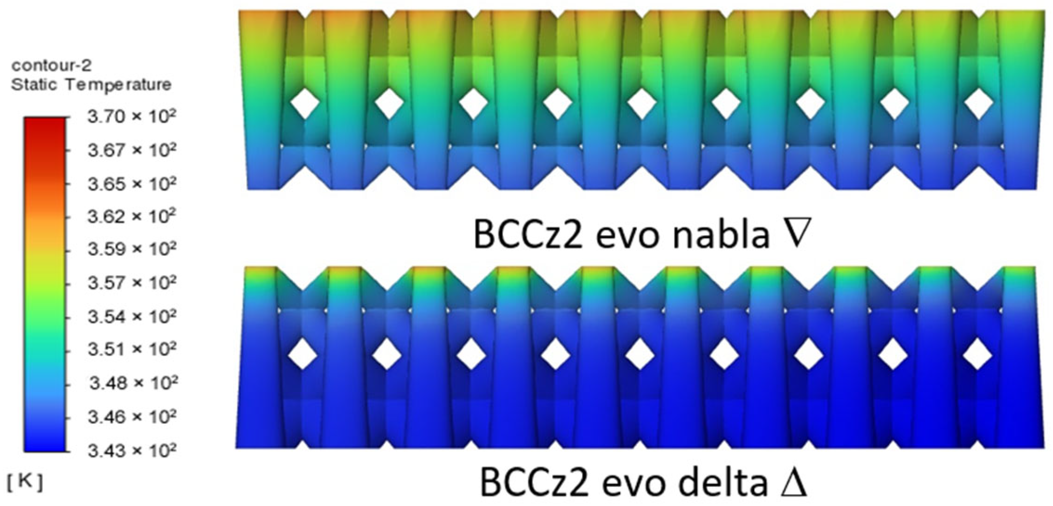
3.4.2. Comparison Between LS Heat Sinks
3.5. Conclusion on the Elementary Structure Heat Sink Study
4. Experimental and Computational Study on Full Scale Demonstrator
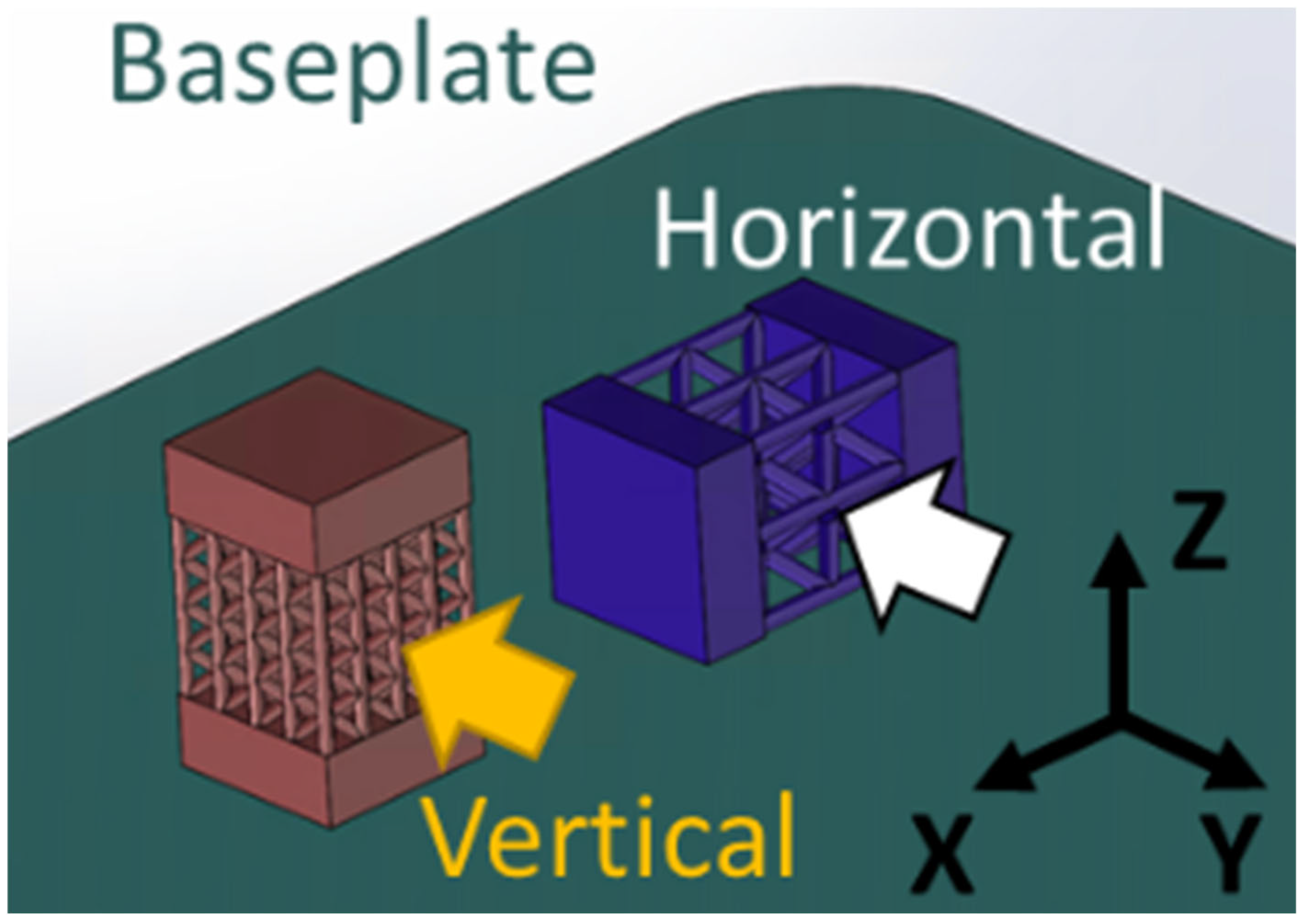
4.1. Demonstrators’ Design and Description
4.2. Full Scale Demonstrator Test Bench Design
4.3. Full Scale Demonstrator Additive Manufacturing
4.4. Full Scale Demonstrator—Results and Discussion
- Improved thermal performance: The implementation of a LS represents a significant step forward in improving the thermal performance of the heat sink, especially compared to traditional straight-fin heat sinks. The LS allows for more efficient heat dissipation.
- Optimization of hydraulic performance: although thermal performance is experiencing substantial improvement, optimizing the hydraulic performance of such LSs is a crucial challenge that requires careful consideration.
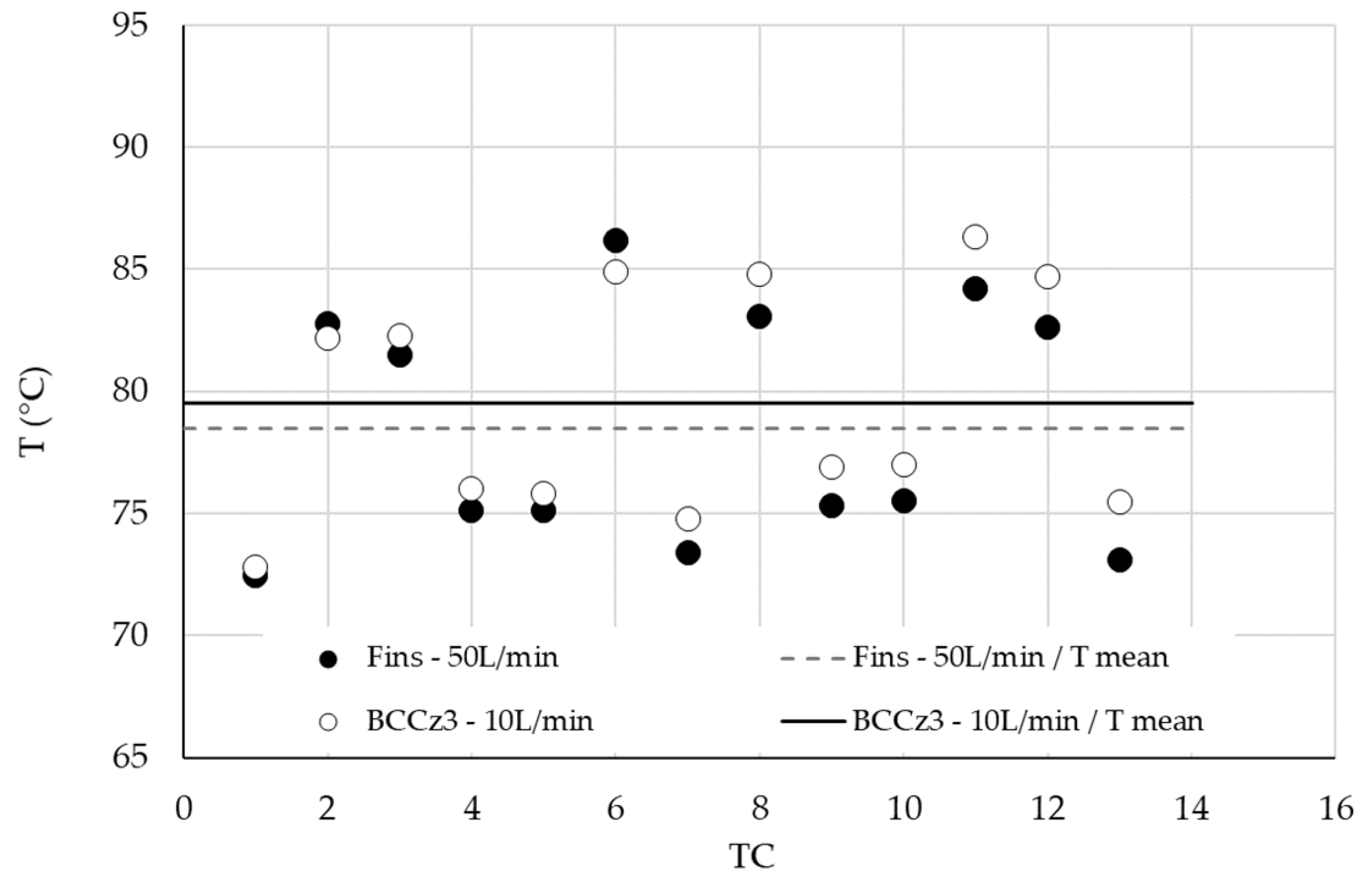
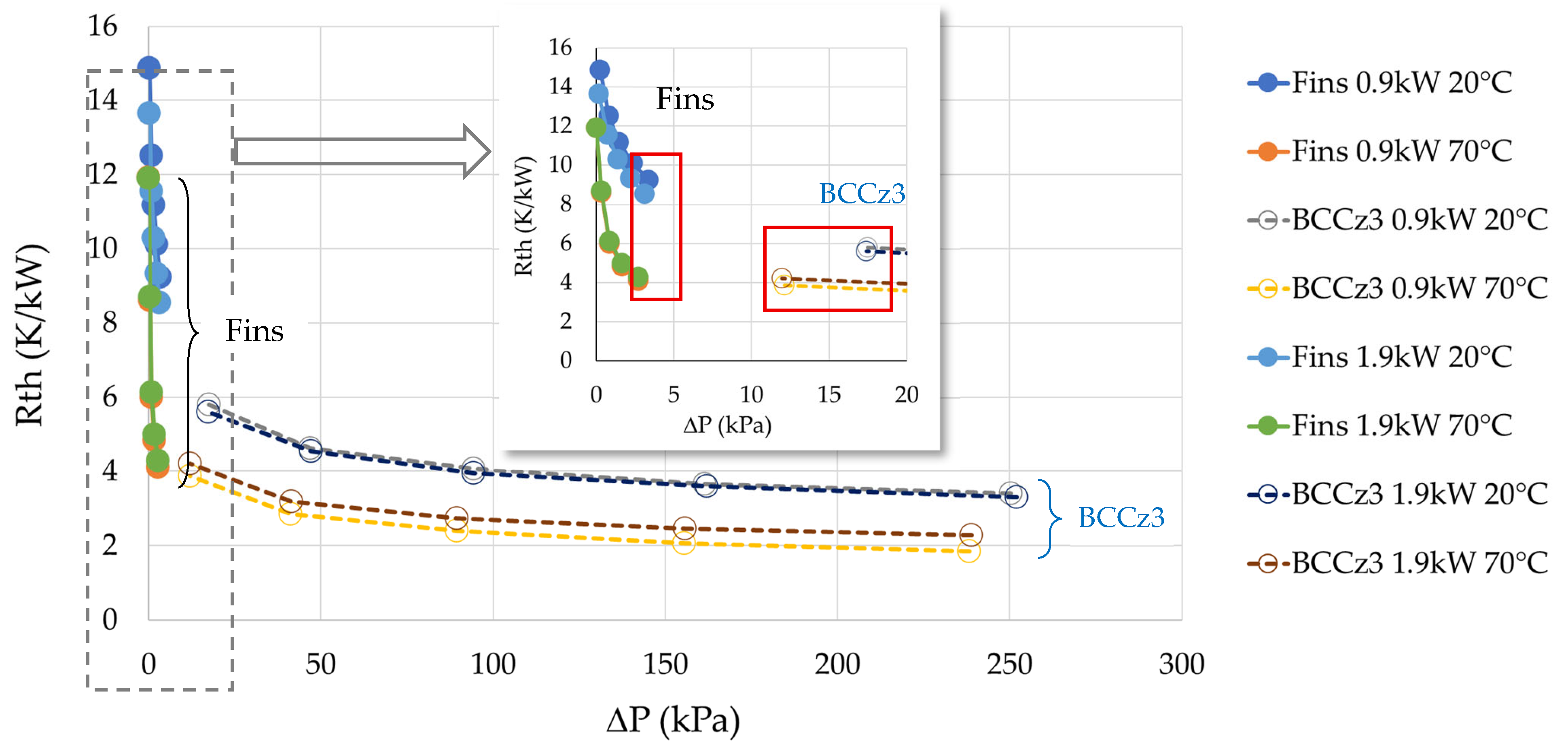
- Impact on flow rate: A notable observation is that by reducing the flow rate in the BCCz configuration, it is possible to maintain comparable thermal performance while keeping the pressure drop at an acceptable level, resulting in a greater operating flexibility. Figure 35 compares the baseplate temperature distribution for the Fins configuration at 50 L/min with that of the BCCz configuration at 10 L/min. The performance of these two cases can be reviewed in Figure 36, focusing on the framed data points.
5. Final Conclusions
6. Suggestions for Further Research
Author Contributions
Funding
Data Availability Statement
Acknowledgments
Conflicts of Interest
Nomenclature
| Pout (Pa) | Coolant outlet pressure |
| ΔP (Pa) | Pressure drop |
| Qv (L/min) | Inlet volume flow rate |
| Rth (K/W) | Equivalent thermal resistance |
| Tref (K) | Reference temperature |
| Tin (K) | Coolant inlet temperature |
| Tbaseplate (K) | Average temperature on the heat sink baseplate |
| ΔT (K) | Local temperature difference between the baseplate and Tin |
| TTC (K) | Local temperature of the baseplate measured by thermocouples |
| Vin (m/s) | Coolant inlet velocity |
| Φ (W) | Heating power |
| Abbreviations | |
| AM | Additive manufacturing |
| BCC | Body centered cubic |
| BCCz | Body centered cubic with additional strut in z direction |
| BD | Build direction |
| CFD | Computational fluid dynamics |
| ES | Elementary Structure |
| FCC | Face centered cubic |
| FCCz | Face centered cubic with additional strut in z direction |
| FSD | Full scale demonstrator |
| HM | Heating module |
| LPBF | Laser powder bed fusion |
| LS | Lattice structure |
| LSs | Lattice structures |
| OTL | Octet-truss lattice |
| RS | Reduced structure |
| TC | Thermocouple |
| TIM | Thermal interface material |
References
- Mohebbi, R.; Mohebbi, M. Advanced Thermal Management in Railway Systems. In Railway Transport and Engineering—A Comprehensive Guide; IntechOpen: London, UK, 2024. [Google Scholar] [CrossRef]
- Umezawa, K. Power Electronic Devices for Railway Vehicles. Power Electron. Technol. Fuji Electr. Rev. 2012, 58, 175–181. [Google Scholar]
- Afonso, J.L.; Cardoso, L.A.L.; Pedrosa, D.; Sousa, T.J.C.; MacHado, L.; Tanta, M.; Monteiro, V. A Review on Power Electronics Technologies for Electric Mobility. Energies 2020, 13, 6343. [Google Scholar] [CrossRef]
- Gregory, T. Optimizing the Thermal Performance of Power Electronics (Technical Article). Available online: https://eepower.com/technical-articles/optimizing-the-thermal-performance-of-power-electronics/ (accessed on 18 April 2025).
- Liu, Y. Thermal Management, Design, and Cooling for Power Electronics. In Power Electronic Packaging; Springer: New York, NY, USA, 2012. [Google Scholar]
- Masaru, K.; Yoshitaka, N.; Kentaro, M.; Yousuke, Y.; Takahiro, Y. Development of Liquid Cooling System with Integrated Traction Converters and Auxiliary Power Supplies for 200-Km/h Commuter Trains. Hitachi Rev. 2017, 66, 161–166. [Google Scholar]
- Abramushkina, E.; Zhaksylyk, A.; Geury, T.; El Baghdadi, M.; Hegazy, O. A Thorough Review of Cooling Concepts and Thermal Management Techniques for Automotive Wbg Inverters: Topology, Technology and Integration Level. Energies 2021, 14, 4981. [Google Scholar] [CrossRef]
- Tseng, P.H.; Tsai, K.T.; Chen, A.L.; Wang, C.C. Performance of Novel Liquid-Cooled Porous Heat Sink via 3-D Laser Additive Manufacturing. Int. J. Heat Mass Transf. 2019, 137, 558–564. [Google Scholar] [CrossRef]
- Schulz-Harder, J. Review on Highly Integrated Solutions for Power Electronic Devices. In Proceedings of the 5th International Conference on Integrated Power Electronics Systems, Nuremberg, Germany, 11–13 March 2008; VDE: Nuremberg, Germany, 2008; pp. 1–7. [Google Scholar]
- Qian, C.; Gheitaghy, A.M.; Fan, J.; Tang, H.; Sun, B.; Ye, H.; Zhang, G. Thermal Management on IGBT Power Electronic Devices and Modules. IEEE Access 2018, 6, 12868–12884. [Google Scholar] [CrossRef]
- Kang, S.S. Advanced Cooling for Power Electronics. In Proceedings of the 2012 7th International Conference on Integrated Power Electron1ics Systems (CIPS), Nuremberg, Germany, 6–8 March 2012; IEEE: Piscataway, NJ, USA, 2012. [Google Scholar]
- Ma, X.; Basem, A.; Singh, P.K.; Dara, R.N.; Almadhor, A.; Hajri, A.K.; Ghandour, R.; Abdullaeva, B.; Ali, H.E.; Babiker, S.G. Efficient Cooling Capability in Microchannel Heat Sink Reinforced with Y-Shaped Fins: Based on Artificial Neural Network, Genetic Algorithm, Pareto Front, and Numerical Simulation. Case Stud. Therm. Eng. 2025, 68, 105936. [Google Scholar] [CrossRef]
- Ismail, M. Experimental and Numerical Analysis of Heat Sink Using Various Patterns of Cylindrical Pin-Fins. Int. J. Thermofluids 2024, 23, 100737. [Google Scholar] [CrossRef]
- Wong, M.; Tsopanos, S.; Sutcliffe, C.J.; Owen, I. Selective Laser Melting of Heat Transfer Devices. Rapid. Prototyp J. 2007, 13, 291–297. [Google Scholar] [CrossRef]
- Kaur, I.; Singh, P. State-of-the-Art in Heat Exchanger Additive Manufacturing. Int. J. Heat Mass Transf. 2021, 178, 121600. [Google Scholar] [CrossRef]
- Careri, F.; Khan, R.H.U.; Todd, C.; Attallah, M.M. Additive Manufacturing of Heat Exchangers in Aerospace Applications: A Review. Appl. Therm. Eng. 2023, 235, 121387. [Google Scholar] [CrossRef]
- Mora, S.; Pugno, N.M.; Misseroni, D. 3D Printed Architected Lattice Structures by Material Jetting. Mater. Today 2022, 59, 107–132. [Google Scholar] [CrossRef]
- Anwajler, B. Potential of 3D Printing for Heat Exchanger Heat Transfer Optimization-Sustainability Perspective. Inventions 2024, 9, 60. [Google Scholar] [CrossRef]
- Pilagatti, A.N.; Piscopo, G.; Atzeni, E.; Iuliano, L.; Salmi, A. Design of Additive Manufactured Passive Heat Sinks for Electronics. J. Manuf. Process 2021, 64, 878–888. [Google Scholar] [CrossRef]
- Shamvedi, D.; McCarthy, O.J.; O’Donoghue, E.; Danilenkoff, C.; O’Leary, P.; Raghavendra, R. 3D Metal Printed Heat Sinks with Longitudinally Varying Lattice Structure Sizes Using Direct Metal Laser Sintering. Virtual Phys. Prototyp. 2018, 13, 301–310. [Google Scholar] [CrossRef]
- Khan, S.A.; Rahman, M.A.; Khraisheh, M.; Hassan, I.G. Advances in 3D Printed Periodic Lattice Structures for Energy Research: Energy Storage, Transport and Conversion Applications. Mater. Des. 2024, 239, 112773. [Google Scholar] [CrossRef]
- Seharing, A.; Azman, A.H.; Abdullah, S. A Review on Integration of Lightweight Gradient Lattice Structures in Additive Manufacturing Parts. Adv. Mech. Eng. 2020, 12, 1687814020916951. [Google Scholar] [CrossRef]
- Yun, S.; Kwon, J.; Lee, D.C.; Shin, H.H.; Kim, Y. Heat Transfer and Stress Characteristics of Additive Manufactured FCCZ Lattice Channel Using Thermal Fluid-Structure Interaction Model. Int. J. Heat Mass Transf. 2020, 149, 119187. [Google Scholar] [CrossRef]
- Dixit, T.; Nithiarasu, P.; Kumar, S. Numerical Evaluation of Additively Manufactured Lattice Architectures for Heat Sink Applications. Int. J. Therm. Sci. 2021, 159, 106607. [Google Scholar] [CrossRef]
- Wang, J.; Qian, C.; Qiu, X.; Yu, B.; Yan, L.; Shi, J.; Chen, J. Numerical and Experimental Investigation of Additive Manufactured Heat Exchanger Using Triply Periodic Minimal Surfaces (TPMS). Therm. Sci. Eng. Prog. 2024, 55, 103007. [Google Scholar] [CrossRef]
- Stimpson, C.K.; Snyder, J.C.; Thole, K.A.; Mongillo, D. Roughness Effects on Flow and Heat Transfer for Additively Manufactured Channels. J. Turbomach. 2016, 138, 051008. [Google Scholar] [CrossRef]
- Maconachie, T.; Leary, M.; Lozanovski, B.; Zhang, X.; Qian, M.; Faruque, O.; Brandt, M. SLM Lattice Structures: Properties, Performance, Applications and Challenges. Mater. Des. 2019, 183, 108137. [Google Scholar] [CrossRef]
- Batikh, A.; Fradin, J.P.; Moreno, A.C. The Impact of Additively Fabricated Lattice Geometry on Liquid-Cooling Heat Sink Performance for Railway Applications. In Proceedings of the 2023 29th International Workshop on Thermal Investigations of ICs and Systems, THERMINIC 2023, Budapest, Hungary, 27–29 September 2023. [Google Scholar]
- Wong, K.K.; Ho, J.Y.; Leong, K.C.; Wong, T.N. Fabrication of Heat Sinks by Selective Laser Melting for Convective Heat Transfer Applications. Virtual Phys. Prototyp. 2016, 11, 159–165. [Google Scholar] [CrossRef]
- Sarap, M.; Kallaste, A.; Ghahfarokhi, P.S.; Tiismus, H.; Vaimann, T. Utilization of Additive Manufacturing in the Thermal Design of Electrical Machines: A Review. Machines 2022, 10, 251. [Google Scholar] [CrossRef]
- Wang, X.; Zhang, D.; Li, A.; Yi, D.; Li, T. A Review on Traditional Processes and Laser Powder Bed Fusion of Aluminum Alloy Microstructures, Mechanical Properties, Costs, and Applications. Materials 2024, 17, 2553. [Google Scholar] [CrossRef] [PubMed]
- Smith, M.; Kim, S.; Lambert, A.; Walde, M.; Lindahl, J.; Mungale, K.; Bougher, T.; Hassen, A.A.; Kunc, V. Maximizing the Performance of a 3D Printed Heat Sink by Accounting for Anisotropic Thermal Conductivity During Filament Deposition. In Proceedings of the 2019 18th IEEE Intersociety Conference on Thermal and Thermomechanical Phenomena in Electronic Systems (ITherm), Las Vegas, NV, USA, 28–31 May 2019; pp. 626–632. [Google Scholar]
- Alauzet, L.; Fradin, J.-P.; Dezalay, A.; Castelan, A.; Tounsi, P.; Regnier, S.; Louis, A.; Anne, C.; Sophie, R.; Jean-Pierre, F.; et al. Innovative 3D Power Module Defaults Detection via Thermal Impedance Analysis and Simulations Innovative 3D Power Module Defaults Detection via Thermal Impedance Analysis and Simulations. In Proceedings of the PCIM Europe 2024—International Exhibition and Conference for Power Electronics, Intelligent Motion, Renewable Energy and Energy Management, Nürnberg, Germany, 11–13 June 2024; pp. 1–9. [Google Scholar]
- Revilla, R.I.; Verkens, D.; Rubben, T.; De Graeve, I. Corrosion and Corrosion Protection of Additively Manufactured Aluminium Alloys—A Critical Review. Materials 2020, 13, 4804. [Google Scholar] [CrossRef] [PubMed]
- Zou, J.; Zhu, Y.; Pan, M.; Xie, T.; Chen, X.; Yang, H. A Study on Cavitation Erosion Behavior of AlSi10Mg Fabricated by Selective Laser Melting (SLM). Wear 2017, 376–377, 496–506. [Google Scholar] [CrossRef]
- Qin, H.; Xu, R.; Lan, P.; Wang, J.; Lu, W. Wear Performance of Metal Materials Fabricated by Powder Bed Fusion: A Literature Review. Metals 2020, 10, 304. [Google Scholar] [CrossRef]
- Naqiuddin, N.H.; Saw, L.H.; Yew, M.C.; Yusof, F.; Poon, H.M.; Cai, Z.; Thiam, H.S. Numerical Investigation for Optimizing Segmented Micro-Channel Heat Sink by Taguchi-Grey Method. Appl. Energy 2018, 222, 437–450. [Google Scholar] [CrossRef]
- Sakanova, A.; Tseng, K.J. Comparison of Pin-Fin and Finned Shape Heat Sink for Power Electronics in Future Aircraft. Appl. Therm. Eng. 2018, 136, 364–374. [Google Scholar] [CrossRef]
- Roussouly, N.; Gallard, F.; Batikh, A.; Fradin, J.-P.; Chaumont, G. Multidisciplinary Optimization of a Heat Exchanger Using Lattice Structures Accounting for Additive Manufacturing Constraints. In Proceedings of the Eccomas Congress 2024 9th European Congress on Computational Methods in Applied Sciences and Engineering, Lisboa, Portugal, 3–7 June 2024. [Google Scholar]
- Toshev, R.; Kolatsis, N.; Shamzzuzoha, A.; Helo, P. The Economics of Additive Manufacturing Ikand Topology Optimisation–A Case Analysis of the Electric Scooter. J. Eng. Des. 2023, 34, 313–338. [Google Scholar] [CrossRef]
- Wong, H.; Dawson, K.; Ravi, G.A.; Howlett, L.; Jones, R.O.; Sutcliffe, C.J. Multi-Laser Powder Bed Fusion Benchmarking—Initial Trials with Inconel 625. Int. J. Adv. Manuf. Technol. 2019, 105, 2891–2906. [Google Scholar] [CrossRef]
- Zhang, Y.; Zhang, G.; Qiao, J.; Li, L. Design and In Situ Additive Manufacturing of Multifunctional Structures. Engineering 2023, 28, 58–68. [Google Scholar] [CrossRef]
- Batikh, A.; Fradin, J.-P.; Moreno, A.C. Investigating the Performance of an Additive Manufactured Lattice Heat Sink versus a Conventional Straight-Fin Heat Sink for Railway Application. In Proceedings of the 2024 30th International Workshop on Thermal Investigations of ICs and Systems (THERMINIC), Toulouse, France, 25–27 September 2024; pp. 1–6. [Google Scholar]


| Topology nw × nh × nl | BCCz | FCCz | OTL | |||
|---|---|---|---|---|---|---|
| d (mm) | Porosity (-) | d (mm) | Porosity (-) | d (mm) | Porosity (-) | |
| 1/2 × 4 × 8 | 0.5 | 0.8 | 0.5 | 0.82 | 0.5 | 0.68 |
| 0.6 | 0.72 | 0.6 | 0.77 | 0.55 | 0.63 | |
| 0.7 | 0.65 | 0.7 | 0.71 | 0.6 | 0.57 | |
| 0.8 | 0.56 | - | - | - | - | |
| 1/2 × 3 × 6 | 0.6 | 0.83 | 0.6 | 0.82 | 0.5 | 0.8 |
| 0.7 | 0.78 | 0.7 | 0.78 | 0.6 | 0.74 | |
| 0.8 | 0.73 | 0.8 | 0.73 | 0.7 | 0.66 | |
| 1/2 × 2 × 4 | 1 | 0.8 | 1 | 0.84 | 0.8 | 0.78 |
| 1.2 | 0.72 | 1.2 | 0.78 | 0.9 | 0.74 | |
| 1.4 | 0.65 | 1.4 | 0.72 | 1 | 0.68 | |
| 1/2 × 1 × 2 | 1.5 | 0.95 | 1.5 | 0.89 | 1 | 0.88 |
| 2 | 0.81 | 2 | 0.81 | 1.5 | 0.78 | |
| 2.5 | 0.73 | 2.5 | 0.78 | 2 | 0.65 | |
| Material | Density (kg/m3) | Thermal Conductivity (W/m·K) | Advantages | Disadvantages |
|---|---|---|---|---|
| Copper alloys | 8960 | 210–400 |
|
|
| Aluminum alloys | 2710 | 110–250 |
|
|
| Stainless Steel | 8000 | 16 |
|
|
| Parameter Set | Roughness Indicators | |||
|---|---|---|---|---|
| Ra [µm] | Rz [µm] | Sa [µm] | Sz [µm] | |
| A | 19.6 | 186 | 19.4 | 205 |
| B | 12.1 | 89.9 | 11.9 | 140 |
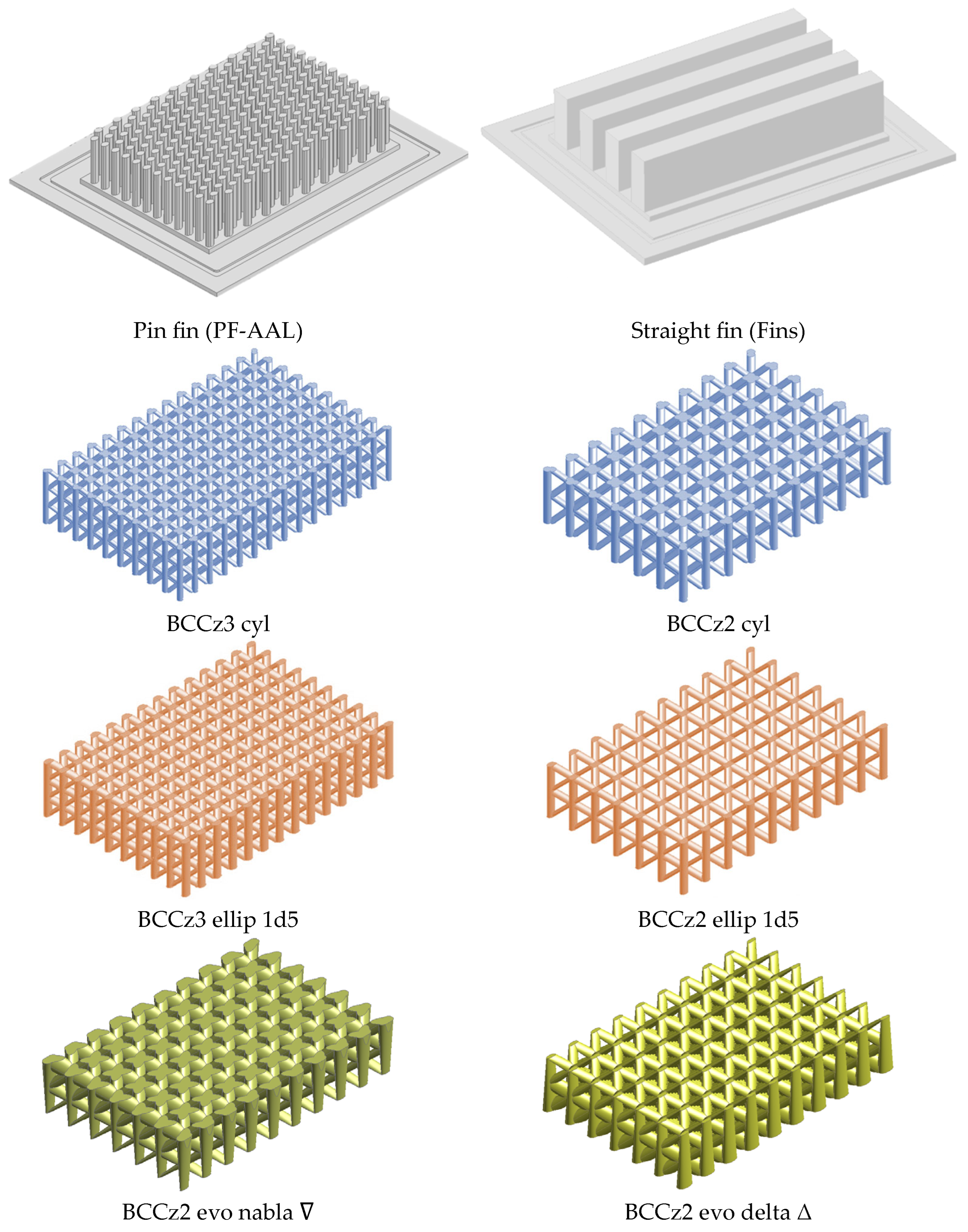
| Configuration Name | N° of Unit Cells H × W × L | Porosity | Strut Cross-Section Shape |
|---|---|---|---|
| BCCz3 cyl | 3 × 9 × 14 | 0.74 | Circular |
| BCCz2 cyl | 2 × 6 × 9 | 0.74 | Circular |
| BCCz3 ellip 1d5 | 3 × 9 × 14 | 0.62 | Elliptical-Ratio = 1.5 |
| BCCz2 ellip 1d5 | 2 × 6 × 9 | 0.79 | Elliptical-Ratio = 1.5 |
| BCCz2 evo nabla ∇ | 2 × 6 × 9 | 0.56 | Evolutive and Elliptical-Ratio = 3 |
| BCCz2 evo delta Δ | 2 × 6 × 9 | 0.56 | Evolutive and Elliptical-Ratio = 3 |
| Configuration Name | LS Total Volume (mm3) | Fluid–Lattice Contact Surface (mm2) | Baseplate–Fluid Contact Surface (mm2) | Baseplate–Lattice Contact Surface (mm2) |
|---|---|---|---|---|
| BCCz3 cyl | 1736.90 | 10,184.37 | 660.71 | 188.63 |
| BCCz2 cyl | 1568.50 | 6504.57 | 695.51 | 153.53 |
| BCCz3 ellip 1d5 | 2284.30 | 10,396.02 | 715.05 | 133.98 |
| BCCz2 ellip 1d5 | 1227.60 | 6129.74 | 783.68 | 65.36 |
| BCCz2 evo nabla ∇ | 2804.20 | 7008.95 | 501.18 | 347.45 |
| BCCz2 evo delta Δ | 2806.90 | 7314.97 | 801.98 | 47.03 |
Disclaimer/Publisher’s Note: The statements, opinions and data contained in all publications are solely those of the individual author(s) and contributor(s) and not of MDPI and/or the editor(s). MDPI and/or the editor(s) disclaim responsibility for any injury to people or property resulting from any ideas, methods, instructions or products referred to in the content. |
© 2025 by the authors. Licensee MDPI, Basel, Switzerland. This article is an open access article distributed under the terms and conditions of the Creative Commons Attribution (CC BY) license (https://creativecommons.org/licenses/by/4.0/).
Share and Cite
Batikh, A.; Fradin, J.-P.; Castro Moreno, A. Computational and Experimental Investigation of Additively Manufactured Lattice Heat Sinks for Liquid-Cooling Railway Power Electronics. Energies 2025, 18, 3753. https://doi.org/10.3390/en18143753
Batikh A, Fradin J-P, Castro Moreno A. Computational and Experimental Investigation of Additively Manufactured Lattice Heat Sinks for Liquid-Cooling Railway Power Electronics. Energies. 2025; 18(14):3753. https://doi.org/10.3390/en18143753
Chicago/Turabian StyleBatikh, Ahmad, Jean-Pierre Fradin, and Antonio Castro Moreno. 2025. "Computational and Experimental Investigation of Additively Manufactured Lattice Heat Sinks for Liquid-Cooling Railway Power Electronics" Energies 18, no. 14: 3753. https://doi.org/10.3390/en18143753
APA StyleBatikh, A., Fradin, J.-P., & Castro Moreno, A. (2025). Computational and Experimental Investigation of Additively Manufactured Lattice Heat Sinks for Liquid-Cooling Railway Power Electronics. Energies, 18(14), 3753. https://doi.org/10.3390/en18143753