1. Introduction
The global drone market is projected to experience robust growth, with Grand View Research estimating the market size at USD 73.06 billion in 2024 and forecasting a compound annual growth rate (CAGR) of 14.3% from 2025 to 2030, reaching approximately USD 163.6 billion by 2030 [
1]. These figures are based on revenue and are reported in nominal (not inflation-adjusted) terms. The methodology involves forecasting revenue growth at global, regional, and national levels; analyzing trends across major sectors (e.g., agriculture, logistics); and considering technological advancements and regulatory developments as key growth drivers [
1]. The geographic scope of these projections is global, with detailed breakdowns available for regions including North America, Europe, Asia Pacific, Latin America, and the Middle East and Africa, as well as key countries within these regions.
Despite this rapid growth, the widespread adoption of drones is hindered by a critical limitation: energy endurance. Traditional battery-powered drones, which rely primarily on lithium-ion batteries, are constrained by their relatively low energy density, typically offering flight times of 20 to 40 min depending on the payload and operating conditions [
2]. This limitation not only restricts the operational ranges of drones but also increases the downtime for recharging, reducing the overall efficiency and increasing the costs. For instance, in commercial delivery services, frequent battery swaps or recharging can significantly delay operations, undermining the economic viability of drone-based logistics [
3].
To address these challenges, researchers and industry stakeholders have turned to hybrid powerplants that combine batteries with alternative energy sources, such as hydrogen fuel cells. Fuel cells offer energy densities up to five times greater than lithium-ion batteries, enabling significantly longer flight times [
4]. However, fuel cells alone cannot meet the dynamic power demands of drones during takeoff, maneuvering, or sudden load changes due to their slower response times. This has led to the development of hybrid systems that integrate batteries for high-power bursts and fuel cells for sustained energy supply. Such systems have demonstrated the potential to extend flight times compared to battery-only configurations [
5]. Despite these advancements, the integration of batteries and fuel cells into a cohesive energy system remains a complex challenge, requiring sophisticated energy management strategies to optimize the performance, efficiency, and longevity.
Energy management systems (EMS) face inherent design tradeoffs when optimizing hybrid UAV powerplants, as each strategy struggles to balance adaptability, computational efficiency, and operational reliability. Rule-based methods [
6] prioritize simplicity through deterministic thresholds (e.g., “activate fuel cell at 40% battery”), but their static decision boundaries fundamentally limit adaptation to variable flight profiles—a 2023 field study showed that these systems achieve only 72–84% of the theoretically optimal energy utilization during wind gust recovery maneuvers [
7]. In contrast, model predictive control (MPC) [
8] introduces dynamic optimization through receding horizon calculations, yet it carries a steep computational cost: real-world implementations require 15–30× more processing power than rule-based systems, often forcing UAVs to accept 200–500 ms control latencies that degrade trajectory tracking by 12–18% [
8]. Machine learning approaches [
9] theoretically transcend these limitations through neural network-based policy optimization, but their “black box” nature creates critical reliability gaps—a recent comparative analysis found that deep reinforcement learning controllers exhibit 23% performance variance when encountering battery degradation patterns that are absent from the training data [
9]. This trilemma underscores a fundamental EMS design challenge: no current strategy simultaneously achieves real-time responsiveness, environmental adaptability, and operational robustness in airborne hybrid systems.
Furthermore, existing studies often overlook the long-term degradation of power sources, which can significantly impact the performance and lifespans of hybrid UAV systems. For example, research on proton-exchange membrane fuel cells (PEMFCs) in hybrid UAVs has demonstrated that exposure to fluctuating ambient conditions and frequent dynamic power demands can accelerate the membrane degradation rates by 15–30% over 1000 operational hours, leading to a 20–40% reduction in the fuel cell lifespan compared to steady-state applications [
10,
11]. Similarly, empirical analyses of lithium polymer (LiPo) batteries in UAVs have shown a measurable decline in efficiency, with a 2.14% loss in output power over 100 flight cycles and a 1.16% drop after just 20 cycles, primarily due to repeated charge–discharge stresses [
12]. These degradation effects have tangible operational consequences: UAVs may require 15–25% larger energy reserves to maintain their original endurance, resulting in an increased takeoff mass, while the need for more frequent fuel cell membrane replacements raises the maintenance costs [
10]. Additionally, as the battery performance deteriorates, hybrid systems often shift a greater workload to the internal combustion engines, causing them to operate less efficiently and increasing the overall fuel consumption by up to 12% over time [
13]. These findings underscore the necessity of degradation-aware energy management in hybrid UAV design and operation [
14].
In a comparative analysis of the energy demand between fixed-wing and multirotor drones, fixed-wing UAVs generally demonstrate superior energy efficiency due to their aerodynamic design, which allows for longer endurance with lower power consumption [
15]. Fixed-wing drones generate lift through their wings, offering a higher lift-to-drag ratio, which enables longer flight times and a greater payload capacity [
16,
17]. In contrast, multirotor drones, which rely on continuous rotor activity to generate lift, consume more power and have shorter flight durations, typically ranging from 15 to 60 min. Innovations in fixed-wing drone technology, such as lightweight materials and hybrid power systems, have further enhanced their energy efficiency, making them ideal for long-duration missions and large-area coverage [
18]. While multirotors are better suited for tasks requiring high maneuverability in confined spaces, fixed-wing drones are increasingly favored for applications that demand extended operational times and broader coverage.
This study addresses these gaps by proposing a novel adaptive energy management system for hybrid powerplants in drones, which combines the strengths of batteries and fuel cells while mitigating their respective limitations. The proposed EMS leverages real-time data on flight dynamics, environmental conditions, and power source health to optimize energy allocation, thereby extending the operational endurance of UAVs. The selection of fuzzy logic over model predictive control (MPC) is based on its simplicity and faster processing times. Fuzzy logic allows for real-time control without requiring prior data for operation, making it more suitable for dynamic, on-the-fly adjustments during flight. In contrast, MPC necessitates knowledge of future values over a prediction horizon to compute the optimal control strategy, which introduces delays and complexity. By integrating fuzzy logic control with a comprehensive system design, the approach aims to strike an optimal balance between performance, efficiency, and cost-effectiveness. Extensive simulations and experimental testing validate the effectiveness of the EMS, demonstrating its potential to reduce operational downtime, lower costs, and enhance the sustainability of drone operations. This work thus provides a significant step forward in the development of efficient, reliable hybrid power systems for UAVs.
The significance of this research extends beyond technical innovation, offering tangible benefits for industries reliant on drone technology. For example, in precision agriculture, longer flight times enable more comprehensive crop monitoring and resource management, potentially increasing yields by up to 20% [
19]. In emergency response scenarios, extended endurance allows drones to cover larger areas and provide critical support for longer durations, saving lives and reducing recovery costs [
1]. By addressing the energy limitations of drones, this work contributes to the broader goal of enabling sustainable, efficient, and scalable UAV technologies. Simulation-based predictions indicate that optimizing energy consumption strategies can significantly extend drones’ flight times and mission capabilities, reinforcing the potential impact of this approach on future UAV deployments.
This study addresses several critical gaps in the current literature on hybrid energy systems for unmanned aerial vehicles. Notably, it bridges the gap between theoretical models and practical applications by integrating experimental hybrid powerplant sizing, degradation modeling for both fuel cells and batteries, and the validation of energy management strategies within a UAV platform [
20,
21]. Previous works have identified degradation mechanisms in fuel cells and batteries, such as voltage degradation and structural damage to the membrane electrode assembly (MEA) in fuel cells and capacity fade in batteries. However, these studies often treat degradation in isolation, without integrating these aspects into a unified model that accounts for the interplay between different energy sources and their combined impact on system longevity [
22]. Additionally, many studies fail to incorporate integrated degradation modeling, which is essential in accurately predicting the long-term performance and lifespans of UAV power systems [
23,
24]. This work also addresses the absence of real-time data utilization in energy management strategies, enabling more adaptive and responsive control systems [
25]. Furthermore, the study explores the development of digital twins, facilitating predictive maintenance and the optimization of energy management strategies. By addressing these deficiencies, this research contributes to the advancement of more reliable, efficient, and sustainable hybrid energy systems for UAVs.
2. Materials and Methods
This section describes the hybrid architecture employed, the aircraft studied, the software developed for real-time control and simulations, the fuel cell degradation models, and the energy management strategies developed (fuzzy logic and passive).
2.1. Hybrid Powerplant Architecture
The architecture used in this study is the result of previous research efforts that explored series and parallel hybrid powerplants, adjusting to the volume, weight, and power requirements of aircraft [
26].
This paper proposes two powerplants optimized in terms of weight and volume: one designed for the implementation of passive control strategies and another for active control strategies. The use of passive control strategies reduces the complexity of the aircraft’s energy management system; however, this significantly decreases the lifespans of the fuel cell and batteries. Therefore, the use of active control strategies, such as fuzzy logic, provides excellent solutions to extend the lifespans of batteries and fuel cells [
27,
28]. Simulation results show that control strategies can increase fuel cell lifetimes by up to 32.8% when operated under specific degradation states. This improvement is achieved by reducing the impacts of the operational conditions, such as load changes, stop/start cycles, idle periods, and high-power operation, which are known to accelerate fuel cell degradation [
27].
Figure 1 illustrates the employed architecture, which consists of a data bus accessed by the onboard computer (Jetson Orin NX). This computer is responsible for maintaining the databases and energy management algorithms. The CUAV V5+ autopilot ensures aircraft stability and controls the motors to follow the planned route. The zero-emission power generation system comprises a battery system that supplies power during flight segments with high power demands, such as takeoff, landing, or vertical-to-horizontal flight transitions, while also storing excess power from the fuel cell. The fuel cell serves as the primary power source, and the battery provides additional power when the fuel cell alone is insufficient.
In the architecture designed for passive control strategies, a DC/DC converter is used in the battery, setting the battery voltage to the minimum voltage of the fuel cell. This configuration ensures that the fuel cell delivers its full power while the battery supplies the remaining power demand. In
Figure 1, the green-colored DC/DC converter represents this implementation. In contrast, for active control strategies, a programmable converter is required to limit the power output of the fuel cell. The orange-colored converter in
Figure 1 represents this component. This electric motor needs an electronic speed controller (ESC) to control the speed of the motor with the power supply.
Fuel cells have a slower operational response; incorporating a hybrid system with batteries enables a faster dynamic response.
2.2. Sizing of Hybrid Power Systems: Battery and Fuel Cell Optimization
An essential aspect of hybrid powerplant design is the optimal sizing of both the battery and fuel cell subsystems to meet mission-specific power and energy demands. The battery is primarily sized to supply high instantaneous power during critical flight phases such as takeoff, hovering, rapid transitions between flight modes, and emergency maneuvers. These transient conditions dictate the battery’s power rating and required capacity, ensuring that voltage stability and performance are maintained without overloading the fuel cell, which is better suited for steady-state power delivery. Batteries are heavy, so this sizing must be considered carefully.
Energy management control strategies that allow battery recharging enable the use of smaller-capacity batteries, reducing the weight and increasing the range [
29]. Fuel cells must be selected to cover the power demand during the longest and most efficient flight segment, which is the cruise segment. Fuel cells with power ratings higher than the cruise segment allow for the recharging of the battery system.
Figure 2a shows the power contribution demanded by each system during the aircraft’s flight, while
Figure 2b presents an example of a flight profile where battery recharging occurs during the cruise segment.
2.3. Application to the Mugin EV-350 Aircraft: Hybridization for Increased Range and Payload
This work focuses on an application in a commercial aircraft with vertical takeoff capabilities, named the Mugin EV-350 [
30]. This aircraft is marketed with a battery system that adds considerable weight, reducing its payload capacity and flight range. Its detailed specifications can be found in
Table 1. This study includes the hybridization of batteries and hydrogen to increase the aircraft’s range and payload capacity. Pre-flight tests have been conducted on a test bench, shown in
Figure 3a. The test bench consisted of a support structure for engine and propeller tests, a fuel cell, a DC/DC converter, a battery, a hydrogen tank, and a computer for monitoring and control.
Figure 3b shows the electric aircraft used, the Mugin EV-350, with a maximum takeoff weight (MTOW) of 22 kg.
2.4. Software Development and Wind Tunnel Experiments
For the acquisition of experimental results and the simulation of the systems, a versatile software program was developed in Python 3.10 [
31] to enable the design, implementation, and validation of control strategies both online and offline using experimental system data.
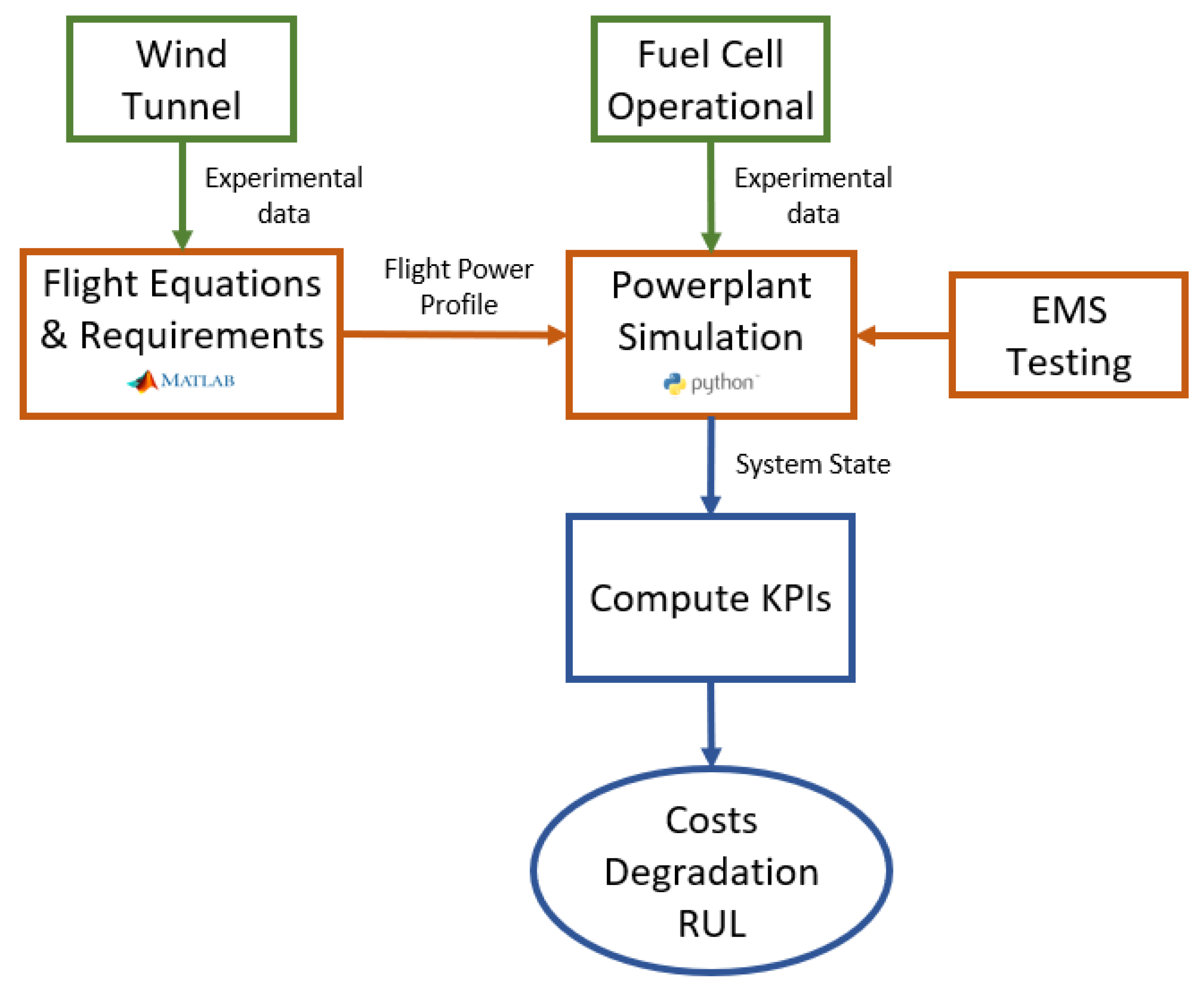
Figure 4 illustrates the procedure used to simulate the energy management control strategies. A MATLAB R2023b-based tool [
32] was developed to process experimental data obtained from wind tunnel tests conducted under various flight conditions using electric motors and propellers [
33,
34]. These data, combined with the corresponding flight equations, enabled the generation of a flight power profile that reflected real system efficiencies. Additionally, experimental data from a 300 W fuel cell were incorporated to support realistic simulations of the control strategies. All resulting data were stored in an InfluxDB database [
35]. Finally, key performance indicators (KPIs)—including the cost, degradation, and the remaining useful life (RUL)—were computed to evaluate and compare the performance of the different EMS implementations. In
Figure 4, green boxes represent the experimental setup, orange boxes correspond to the simulation framework, and blue indicates the KPI evaluation process.
The flight profile described outlines the different phases of a drone’s operation, each with specific thrust requirements to simulate a realistic flight scenario. By implementing the UAV flight dynamics equations in MATLAB and incorporating experimental data obtained from motor performance tests conducted in a wind tunnel, the expected power profile during flight is derived. This resulting power profile is presented in
Figure 5. The six segments of the flight profile are described in detail as follows.
Warm-up (30 s at thrust (T) = 0.75 × weight (W)). This initial segment allows the drone’s systems to stabilize and warm up, ensuring that the components (motors, sensors, and battery) are properly prepared for the rest of the flight.
The thrust is set to 0.75 times the weight of the drone, which is lower than the drone’s full weight, to avoid unnecessary wear on the systems. This lower thrust helps to gradually bring the drone into action without inducing stress on its components.
Takeoff with T = 1.25 W for 10 s. In this phase, the drone needs a significant increase in thrust to overcome gravity and lift off the ground.
The thrust of 1.25 times the weight ensures that the drone has enough power to initiate a takeoff, lifting off smoothly while avoiding instability that could arise from underpowered thrust.
Hovering with T = W for 10 s. Once the drone has taken off, it enters a hovering state, where it remains stationary in the air.
To hover, the thrust is set equal to the weight of the drone. This condition ensures that the drone is balanced, with the lift force exactly counteracting the force of gravity, allowing it to remain at a fixed altitude without any upward or downward movement.
Transition from hovering to forward flight for 1 min. The transition phase begins with the drone hovering and then gradually accelerating to forward flight.
This phase represents the changeover from a vertical flight mode (hovering) to a horizontal flight mode (forward flight), which requires precise control of the thrust to maintain stability during the shift in aerodynamic forces.
The gradual transition takes place over one minute to ensure smooth and stable control during this maneuver, which may involve adjusting both the thrust and the orientation of the drone.
Cruise for 3 h. During the cruise phase, the drone reaches stable forward flight, where it maintains a constant speed and altitude.
The cruise phase is the longest and simulates the duration of a flight mission, where the drone performs tasks such as surveying, monitoring, or delivery.
In this phase, the drone typically operates at an optimal balance of power consumption and efficiency, sustaining steady flight with minimal energy expenditure.
Landing for 20 s with T = 0.6 W. To conclude the flight, the drone begins its descent.
The thrust during landing is reduced to 0.6 times the weight, which is lower than the thrust required for takeoff. This is to ensure a gentle, controlled descent, avoiding any abrupt forces that could harm the drone or its payload.
The 20 s duration of this phase allows the drone to decelerate smoothly and land safely on the ground.
2.5. Fuel Cell Degradation Model
The fuel cell used in this study is a proton-exchange membrane fuel cell with nominal power of 300 W. In this study, we use three fuel cells of 300 W. The fuel cell converts hydrogen energy into electrical power () through a series of electrochemical reactions. A fraction of the generated power is consumed by auxiliary systems (air supply, cooling systems, purging, controllers, etc.) to ensure the proper operation of the overall system. The auxiliary power consumption is unknown and varies during the fuel cell’s operation. The minimum power required by these auxiliary systems is estimated at 10 W, based on the observed consumption when no load draws power.
Figure 6 shows the polarization curve of the fuel cell at an ambient temperature of 25 °C, 50% relative humidity, and a hydrogen supply pressure of 0.7 bar. It represents the cell’s voltage output as a function of current density. This is a crucial tool in evaluating fuel cell performance under various operating conditions.
During the operation of the fuel cell, the mass of consumed hydrogen (
) can be calculated as [
36]
where
is the fuel cell efficiency,
is the theoretical power supplied by hydrogen, and
is the lower heating value of hydrogen (120,000 J/g) [
37]. To calculate the mass of consumed hydrogen, it is necessary to quantify
using the following equation:
where
is the hydrogen flow rate, obtained by fitting an experimental linear equation [
38]. Obtained from experimental data provided by the manufacturing company, the hydrogen consumption for a 300 W power output is
g/min [
39].
where
,
is the number of cells, and
is the fuel cell output voltage.
The reduction in fuel cell efficiency is associated with inefficiencies in heat dissipation, among other factors. To illustrate the influence of factors that can degrade fuel cell performance, data were collected under different environmental conditions, after five months of fuel cell inactivity, and after normal cell degradation due to operation. The fuel cell operating range can be divided into three power intervals: low (
), medium (
), and high (
) [
36]. These intervals define the medium operating zone as the optimal region for fuel cell operation, where degradation is reduced and the efficiency per unit of generated electrical power is higher [
40].
Developing fuel cell degradation models requires a deep understanding of the degradation mechanisms, which involve complex processes influenced by multiple electrochemical and mechanical factors [
41]. Other studies indicate that membrane degradation can severely impact the normal operation of the fuel cell [
42]. The primary factors contributing to degradation include the startup and shutdown cycles, power oscillations, and extreme power outputs (both high and low) [
42]. Therefore, the fuel cell lifetime estimation model [
40] is used:
where
represents the average number of startup and shutdown cycles per hour,
is the average time operating in the low-power zone per hour,
is the average number of power transitions per hour,
is the average time operating in the medium-power zone per hour, and
is the average time operating in the high-power zone per hour.
is the average voltage degradation rate per hour during fuel cell operation. The coefficients
, and
represent the voltage degradation rates per cycle and per hour for each operating condition.
is the allowable voltage degradation of a single fuel cell at the end of its lifespan (typically considered as a 10% decrease from the nominal voltage [
40]), and
is the estimated remaining useful life of the fuel cell. For this study,
V is considered.
Table 2 presents the voltage degradation rates used as reference values.
2.6. Battery Model
In this study, a six-cell LiPo battery system configured in a 6S1P arrangement is employed as a supplementary energy source for scenarios in which the instantaneous power demand exceeds the output capacity of the fuel cell. The battery has a nominal energy capacity of 729.6 Wh (22.8 V, 32 Ah). In the original powerplant configuration of the Mugin EV-350, two such battery packs were utilized. Under the proposed hybrid configuration, only a single battery is required, resulting in a significant reduction in battery weight without compromising the overall operational performance.
The state of charge (SOC) of the battery is an indicator of the remaining battery capacity relative to its nominal capacity, expressed as
where
is the nominal capacity of the battery system,
is the initial SOC, and
is the battery efficiency (typically 1 for discharge and 0.95 for charge).
With the use of the battery as an energy supply or absorption system, its capacity gradually degrades, reaching an irreversible physical state and undergoing electrochemical changes [
43]. To estimate the decrease in the nominal capacity of the battery, a battery degradation model, developed in [
43], is employed. According to the Arrhenius equation, the percentage decrease in the capacity of battery cells,
, relative to their initial capacity (100%) can be expressed as [
44]
where
is the battery c-rate, and B is a coefficient as a function of the c-rate, with values found in
Table 3. Additionally,
is the activation energy, R is the ideal gas constant (8.31 J/(molK)), T is the temperature of the battery cells (considered 298.2 K (25 °C)),
is the amount of energy provided by the battery during cycles, and z is a coefficient given by a law. Based on [
44],
, and
is obtained as
For a cell, a 20% reduction in its nominal capacity is considered the end of its life, and its energy at the end of life (
)
On the other hand, the total number of cycles (
) until the end of life can be obtained as [
45]
The state of health (SOH) of the battery is defined as [
45]
This model allows the prediction of future battery states for predictive control strategies like MPC.
2.7. Fuzzy Logic
Fuzzy logic, based on the principles of fuzzy set theory, allows for the effective handling of imprecision and uncertainty. Unlike conventional control systems, which operate on binary logic, fuzzy logic works across a continuous spectrum, enabling decision-making in conditions of ambiguity. This characteristic is particularly useful in controlling vertical takeoff and landing (VTOL) aircraft, where the flight conditions can vary unpredictably due to environmental factors, load changes, and other dynamic variables. An overview of fuzzy logic operation is illustrated in
Figure 7.
In the context of aircraft powered by hydrogen fuel cells and batteries, fuzzy logic is used to manage the distribution of power between the different propulsion systems, optimizing the performance and prolonging the lifespans of the components.
Designing a fuzzy controller for VTOL aircraft involves defining a series of rules based on experience and system knowledge. These rules, expressed in linguistic terms, are translated into membership functions that describe the relationship between input variables (such as battery charge level and power demanded by the motors) and output variables (such as fuel cell power). The fuzzy inference process converts these inputs into concrete actions by evaluating the defined rules and combining their results.
Table 4 shows the implemented logical rules. The rules have been designed using experimental knowledge to prioritize medium- and high-power states of the fuel cell, while maintaining appropriate charge levels in the battery system. The specification of the rules of the fuzzy logic controller depends on the designer’s knowledge about the supplies and motor constraints; intuitive and practical aspects regarding the propulsion mechanism’s dynamic behavior; and successive experiments to assure the process’s robustness and reliability [
46,
47]. Since the flight process can be divided into five stages according to the required power—takeoff and landing, transition, climbing, cruise, and descent—the input variable, the demand power (
), is classified into five levels: very high (VH), high (H), medium (M), low (L), and very low (VL) [
48]. Similarly, the state of charge (
) is classified into three levels: high (H), medium (M), and low (L). For the output variable of the fuzzy controller, the fuel cell power (
), its upper limit is determined by the maximum output power of the fuel cell and the converter efficiency. The maximum output power of the fuel cell and converter combination in this work is 873 W. The output variable of the fuzzy controller is classified into five levels: VH, H, M, L, and VL. This results in 15 logical rules.
Figure 8a,b show the membership functions designed for the input variables to the fuzzy logic system. Since these were designed using a heuristic approach, further fine-tuning techniques may be explored. The output variable of the system is the power generated by the fuel cell, and the membership function for this is shown in
Figure 9. For simplification, the system architecture models the use of three fuel cells as a combined equivalent power source of 900 W. The computational performance of the developed control framework was evaluated during operation, yielding a processing time of less than 0.1 ms. Benchmark testing was conducted on a system equipped with a 13th-Gen Intel
® Core™ i7-1355U processor (1.70 GHz) with 16 GB RAM and running Windows 11. The low processing latency demonstrates the framework’s suitability for real-time embedded applications.
4. Discussion
The results of this study demonstrate clear improvements in reducing the operational costs and extending the aircraft’s endurance, achieving an increase in flight autonomy of 50% compared to conventional configurations. This enhancement is particularly significant for missions requiring extended loitering or range, such as surveillance, mapping, or delivery in remote areas. While previous research has investigated hybridization in quadcopters—aircraft that benefit from lower power requirements during takeoff due to their lightweight nature and vertical lift mechanisms—this work advances the field by adapting hybrid energy management to fixed-wing UAVs with horizontal flight capabilities. Fixed-wing platforms are inherently more efficient in cruise flight, offering better energy utilization, and thus present greater potential for endurance optimization when equipped with intelligent energy control strategies.
During the development and testing phases, several areas for system enhancement were identified, particularly related to the fuel cell shutdown process. Experimental results demonstrated that implementing a controlled and gradual reduction in power output during shutdown helped to mitigate abrupt transients, thereby improving the system’s stability and extending the fuel cell’s longevity. Specifically, as shown in
Table 6, the application of a shutdown strategy using an absolute reference with a 50% slope yielded an improvement of up to 13.54% in the estimated remaining useful life compared to operation without a shutdown mechanism. Additionally, the study emphasizes the operational benefits of maintaining a near-constant power output from the fuel cell, which reduces power fluctuations and associated degradation. These findings also highlight the importance of appropriate fuel cell sizing; systems in which the fuel cell’s rated power falls below the aircraft’s steady-state cruise demand were found to restrict the effectiveness of intelligent energy management strategies, leading to suboptimal performance and accelerated wear.
Building upon these findings, future studies should focus on the implementation of control strategies inspired by passive hybrid systems, wherein the fuel cell operates at a constant baseline power output for most of the mission, supplemented by the battery during transients or periods of increased demand. In this context, small and gradual adjustments to the fuel cell power output may be introduced to enhance the overall efficiency while preserving the system’s simplicity and reliability.
Another critical area for future research involves optimizing fuzzy logic-based energy management strategies. Efforts should focus on developing methods for both the offline and online tuning of fuzzy logic rules, potentially using optimization algorithms or machine learning techniques. These approaches could allow for adaptation based on mission profiles, performance objectives, or changing environmental conditions. Furthermore, exploring ways to improve the fuzzy control system through the use of confidence intervals and sensitivity analysis could provide deeper insights into its performance, enhancing the gains in endurance and reducing the costs. In addition, implementing techniques to manage the power slope variation of the fuel cell, such as model predictive control or reinforcement learning, could offer more precise control, improving the overall system efficiency and resilience. Adaptive fuzzy logic systems could learn from past flights and continuously refine their rules, providing a dynamic and data-driven approach to UAV energy management.
Moreover, it would be valuable to explore power management strategies that incorporate predefined constraints on the fuel cell power increase rates to limit rapid transitions and reduce thermal and mechanical stresses. Incorporating flight mission planning into the control algorithm—where the expected power demand is known in advance—could further improve the energy distribution and prolong the system’s life.
To validate the real-world applicability of these strategies, full-scale experimental flight tests should be conducted, involving complete UAV missions under a range of operational conditions. These tests would enable the assessment of the control performance under realistic aerodynamic loads, sensor noise, and external disturbances. Additionally, future work should focus on improving the fuel cell degradation model through experimental testing under different operational conditions, including temperature, pressure, and humidity variations, as well as fluctuations in these parameters, to provide more accurate insights into fuel cell performance and longevity. Experimental validation of the battery degradation model, particularly under higher current loads typical in UAV operations, should also be prioritized to enhance model accuracy. Furthermore, the integration of digital twins—using real-time data for system simulation and prediction—could support the development of more precise models. Future work should also explore the integration of environmental adaptability into the control system, enabling the UAV to dynamically respond to varying wind conditions, ambient temperature fluctuations, and altitude-related performance shifts.
In addition, future work should address the co-optimization of the hybrid energy system design, which includes the sizing and selection of fuel cells, batteries, and hydrogen storage, alongside the development of control strategies. A system-level design framework that jointly considers factors such as the energy capacity, weight, mission requirements, and control performance would enable the creation of more efficient, customized UAV configurations. Furthermore, improvements to the current framework will enhance the operation of energy management strategies by allowing the use of real-time data for both simulation purposes and real-world applications. Future versions of the framework should focus on improving the digital twins, enabling the implementation of more efficient energy management strategies. These advancements would provide better predictions of system behavior, optimize the energy consumption, and ultimately enhance the UAV’s operational efficiency.
Lastly, the inclusion of fault detection and recovery mechanisms in the energy management architecture is essential in enhancing its reliability and ensuring safety during autonomous missions. Such features could allow the system’s performance to degrade gradually in the event of a component failure, maintaining safe operation until recovery or landing is possible.


