Article

Torsional Vibration Characterization of Hybrid Power Systems via Disturbance Observer and Partitioned Learning

School of Mechanical Engineering, Tianjin University, Tianjin 300072, China
*
Author to whom correspondence should be addressed.
Energies 2025, 18(11), 2847; https://doi.org/10.3390/en18112847
Submission received: 6 May 2025 / Revised: 26 May 2025 / Accepted: 27 May 2025 / Published: 29 May 2025
(This article belongs to the Special Issue Hybrid Electric Powertrain System Modelling and Control)

Abstract

:
The series–parallel hybrid powertrain combines the advantages of both series and parallel configurations, offering optimal power performance and fuel efficiency. However, the presence of multiple excitation sources significantly complicates the torsional vibration behavior during engine startup. To accurately identify and analyze the torsional vibration characteristics induced by shaft resonance in this process, a torsional vibration feature identification algorithm based on disturbance observation and parameter partition learning is proposed. A simplified model of the drivetrain shaft system is first established, and an extended state Kalman filter (ESKF) is designed to accurately estimate the torque of the torsional damper. The inclusion of extended disturbance states enhances the model’s robustness against system uncertainties. Subsequently, continuous wavelet transform (CWT) is employed to identify the resonance characteristics in the torsional vibration process from the torque signal. Combined with the parameter partition learning strategy, resonance frequencies are utilized to infer key system parameters. The results demonstrate that, under a 20% perturbation of structural parameters, the observer model with fixed parameters yields a root mean square error (RMSE) of 10.16 N·m for the torsional damper torque. In contrast, incorporating the parameter self-learning algorithm reduces the RMSE to 2.36 N·m, representing an 85.2% improvement in estimation accuracy. Using the Morlet wavelet with a frequency resolution parameter (VPO) of 15 at a 50 Hz sampling rate, the identified resonance frequency was 14.698 Hz, showing a 1.1% deviation from the actual natural frequency of 14.53 Hz.

1. Introduction

The adverse effects of global climate change on ecosystems, economic development, and human health have become increasingly evident. Achieving carbon peaking and carbon neutrality targets is an effective strategy to address this pressing global challenge [1]. Hybrid electric vehicles (HEVs), which integrate two or more power sources, utilize energy management systems to promote low-cost, sustainable transportation modes [2]. These systems not only reduce vehicular exhaust emissions but also enhance performance optimization [3]. As a result, in recent decades, new energy vehicles—including battery electric vehicles, hybrid electric vehicles, and fuel cell vehicles—have seen widespread adoption [4]. However, due to their unique multi-power source architecture, HEVs exhibit special and complex vibration characteristics. In particular, torsional vibrations in the drivetrain are likely to occur during power source transitions [5]. This issue becomes especially prominent during engine start-up, where variations in excitation frequency may induce resonance, significantly compromising ride comfort [6]. Therefore, understanding the torsional vibration characteristics of hybrid powertrain systems is essential for improving vehicle performance and advancing the application of hybrid technologies.
Torsional vibration mitigation methods for vehicle drivetrains are generally categorized into passive and active damping strategies. Passive methods aim to suppress vibration through adjustments in the system’s inertia, stiffness, or damping—such as the use of dual-mass flywheels, flexible universal joints, or optimized torsional dampers [7]. However, these approaches often involve lengthy development cycles and increased system complexity. In contrast, active damping methods, which regulate the output torque of power sources or control clutch engagement in real time, offer greater flexibility and adaptability in hybrid powertrains. Given that hybrid systems incorporate both engines and electric motors as controllable actuators, active damping approaches can be further classified into three primary strategies: (1) attenuation of torque fluctuations originating from the engine itself [8,9,10]; (2) optimization of clutch engagement strategies to reduce vibration transmission [11,12,13,14]; and (3) compensation for engine torque oscillations using electric motor outputs [15,16,17,18,19]. Nevertheless, the effectiveness of torsional vibration suppression hinges on a robust and comprehensive performance evaluation framework. Current studies primarily adopt time-domain analysis methods, using metrics such as impact intensity and engine torque fluctuations to evaluate vibration mitigation. However, during engine start-up in HEVs, the system’s excitation frequency changes rapidly with rotational speed, exhibiting distinct non-stationary characteristics. As a result, conventional time-domain approaches struggle to accurately capture transient frequency-domain features. To enhance the specificity and effectiveness of control strategies, it is necessary to incorporate transient frequency-domain indicators into controller evaluation, thereby enabling better identification of critical resonance bands and dominant excitation sources.
Moreover, existing studies often lack direct observation of torque transients that characterize system excitation, leading to mismatches between the motor compensation torque and actual transmitted torque, thus undermining vibration control effectiveness. Due to limitations in cost, reliability, and installation, high-precision torque sensors are difficult to apply in mass-produced vehicles, making torque estimation based on existing sensor measurements the mainstream solution [20,21,22]. In scenarios with well-defined dynamic models and minimal disturbances, structural observers have been widely used for drivetrain state estimation [23,24,25,26]. However, as system coupling intensifies and disturbances accumulate, traditional observers face limitations in both accuracy and robustness, prompting interest in stochastic filtering techniques—most notably Kalman filtering [27,28,29].
Kalman filters enhance estimation accuracy under nonlinear and uncertain input conditions by statistically modeling process and measurement noise and dynamically adjusting error covariance and filter gain. These filters are particularly well-suited for hybrid systems. Xue et al. [30] developed a dynamic model of a dual-motor system and designed a Kalman filter for online prediction of clutch friction torque during slip phases. Hao et al. [31] proposed an extended Kalman filter (EKF)-based method to estimate torque deviations between nominal and actual engine outputs, incorporating an improved least squares algorithm for adaptive parameter correction, thereby improving robustness to model discrepancies. Zhao et al. [32] constructed a three-dimensional clutch dynamics model based on the nonlinear characteristics of dual-clutch transmission (DCT) shift processes and employed an unscented Kalman filter (UKF) to estimate real-time transmitted torque, demonstrating high accuracy and control effectiveness in strongly coupled systems.
In terms of transient time-frequency characteristics extraction, Liu et al. [33] proposed a fault diagnosis framework combining short-time Fourier transform (STFT) with an enhanced instantaneous frequency estimation algorithm. The method utilizes band-pass filtering to isolate optimal frequency bands and employs envelope time-frequency analysis to identify fault characteristic frequencies. Zhang et al. [34] used STFT to convert vibration signals into time-frequency images and designed a convolutional neural network with stacked dual convolution layers for end-to-end fault classification. Xiang Chuan et al. [35] extracted frequency-domain features using fast Fourier transform (FFT) combined with decimation-in-time algorithms. Traditional STFT and FFT techniques are limited by their use of fixed time-frequency windows, making it difficult to capture transient impacts and modulation features in non-stationary signals. By contrast, Continuous Wavelet Transform, with its multi-scale adaptive decomposition capabilities [36], provides more effective representation of localized features in non-stationary vibration signals. This enhances time-frequency resolution and feature fidelity. Verstraete et al. [37] further integrated STFT, wavelet transform (WT), and Hilbert–Huang transform (HHT) to convert raw vibration signals into time-frequency representations, which were then input into CNNs for automatic feature extraction and intelligent fault diagnosis. This method demonstrated strong robustness and high accuracy even in the presence of noise interference.
In summary, the torsional vibration issue observed during the engine start-up process of hybrid powertrain systems is essentially caused by resonance within the driveline, which leads to vibration amplification. This not only affects the system’s smoothness but may also accelerate fatigue damage to components. Therefore, accurately identifying the resonance characteristics—namely, frequency and amplitude—is critical for parameter optimization and vibration suppression. However, existing studies still face limitations in the quantification of torsional vibration, torque estimation, and transient time-frequency feature extraction. Torsional vibration suppression typically relies on time-domain indicators such as torque fluctuation and impact intensity, which are insufficient for comprehensively describing system dynamics. Traditional torque observation methods are vulnerable to model parameter uncertainties and external disturbances under complex operating conditions, resulting in poor estimation robustness. In terms of time-frequency analysis, conventional methods such as the STFT and FFT are constrained by fixed window lengths and assumptions of signal stationarity, leading to inadequate sensitivity to localized resonance characteristics.
The major contributions of this paper are as follows:
  • The unmodeled components, such as engine torque, are incorporated as disturbance states and embedded into a Kalman observer framework to compute the observer gain, enabling effective estimation of the torque at the torsional damper.
  • A continuous wavelet transform is applied to the estimated torsional damper torque signal to extract its time-frequency features, thereby identifying the frequency-domain characteristics of transient torsional vibrations.
  • Based on a shafting rotational dynamics model and a natural frequency model, structural parameters within the observer framework are estimated.
The rest of this paper is organized as follows. Section 2 presents the methodology for identifying transient frequency-domain characteristics. Section 3 validates the proposed algorithm through simulation experiments. Section 4 summarizes the paper and outlines the main conclusions.

2. Materials and Methods

The proposed adaptive torsional vibration observation and identification framework, integrating disturbance rejection observation and parameter partition learning strategies, is illustrated in Figure 1.
First, a dynamic model of the drivetrain system is established, and its time-frequency domain response during the hybrid powertrain startup process is analyzed. Subsequently, an extended state Kalman filter observer is designed by incorporating an expanded disturbance state, enhancing the system’s robustness against model disturbances and enabling precise observation of torsional damper torque. The observed torque signal is then fed into a continuous wavelet transform module to achieve accurate resonance feature extraction and identification. Finally, the identified resonance frequencies serve as feedback signals for the parameter-partitioned hybrid learning algorithm, which adaptively updates the observer parameters, thereby optimizing the observation model’s performance.
This study focuses on the adaptive observation and identification of torsional vibration resonance characteristics in shaft systems, while torsional vibration suppression and optimization control fall beyond its scope. Nevertheless, the extracted resonance features provide critical input for subsequent active torsional vibration control, offering essential data support and technical foundations for vibration suppression and system optimization in hybrid powertrain systems.

2.1. Drivetrain System Model

As shown in Figure 2, this study focuses on a series–parallel hybrid powertrain system where power from the internal combustion engine (ICE) and the integrated starter-generator (ISG) is coupled through a gear transmission mechanism. This configuration enables cooperative operation of both power sources to drive the vehicle. The key component parameters of the transmission system are shown in Table 1, which are either directly provided by the original equipment manufacturer (OEM) or calculated based on the relevant geometric parameters supplied by the OEM.
Due to the nonuniform mass and elastic distribution in vehicle drivetrain systems, component simplification is essential for dynamic modeling, requiring the development of a discretized multi-degree-of-freedom model. This study employs the lumped mass method, with the following simplification principles for drivetrain components:
  • Engine Assembly: The crankshaft, connecting rod-piston mechanism, and accessories are simplified as an equivalent rotational inertia element. This approach is justified by the relatively uniform mass distribution of rotating components and the negligible periodic influence of the connecting rod-piston mechanism on the system’s rotational inertia.
  • Dual-Mass Flywheel: Modeled as two interconnected inertia elements (primary and secondary mass blocks), linked through a torsional spring-damper system. This configuration effectively buffers engine torque fluctuations and mitigates drivetrain vibrations.
  • Intermediate Shaft Assembly: The shaft segment between the dual-mass flywheel’s driven side and the clutch (including intermediate drive shafts and gears) is reduced to a single inertia element.
  • Motor Shaft System: The shaft section between the gear engagement point and motor side is represented as an inertia element to capture drivetrain path flexibility.
  • Motor Rotor: Due to its substantial rotational inertia, the rotor is modeled as a lumped inertia element to accurately reflect its dynamic role in torsional vibration responses.
To simplify the modeling process and enhance computational efficiency, all connection structures in this study are assumed to behave as linear systems, with constant stiffness, damping, and inertia parameters. Highly nonlinear terms and parameters that vary dynamically with operating conditions are not considered. Although the proposed model effectively captures the torsional characteristics and primary dynamic trends of the powertrain system, it may exhibit reduced accuracy under extreme operating conditions. Future work may incorporate nonlinear modeling techniques and experimental correction mechanisms to further improve the model’s accuracy and applicability. The resulting lumped-mass representation of the hybrid powertrain system is shown in Figure 3.
The rotational dynamic equations for the lumped mass model of the drivetrain system, illustrated in Figure 3, are derived as follows:
J 1 φ ¨ 1 + C e 1 φ ˙ 1 + K 1,2 φ 1 φ 2 + C 1,2 φ ˙ 1 φ ˙ 2 = T I C E J 2 φ ¨ 2 K 1,2 φ 1 φ 2 + K 2,3 φ 2 φ 3 C 1,2 φ ˙ 1 φ ˙ 2 + C 2,3 φ ˙ 2 φ ˙ 3 = 0 J 3 φ ¨ 3 K 2,3 φ 2 φ 3 + K 3,4 φ 3 φ 4 C 2,3 φ ˙ 2 φ ˙ 3 + C 3,4 φ ˙ 3 φ ˙ 4 = 0 J 4 φ ¨ 4 K 3,4 φ 3 φ 4 + K 4,5 φ 4 φ 5 i C 3,4 φ ˙ 3 φ ˙ 4 + C 4,5 φ ˙ 4 φ ˙ 5 i = 0 J 5 φ ¨ 5 K 4,5 i φ 4 φ 5 i + K 5,6 φ 5 φ 6 C 4,5 i φ ˙ 4 φ ˙ 5 i + C 5,6 φ ˙ 5 φ ˙ 6 = 0 J 6 φ ¨ 6 + C e 6 φ ˙ 6 K 5,6 φ 5 φ 6 C 5,6 φ ˙ 5 φ ˙ 6 = T I S G
where J 1 ,   J 2 ,   J 3 ,   J 4 ,   J 5 ,   J 6 represent the rotational inertia of the engine, primary mass flywheel, secondary mass flywheel, engine assembly shaft segment, motor assembly shaft segment, and motor, respectively; φ 1 φ 6 represent the torsional angular displacements of the above rotational inertias, with the first derivatives being the torsional angular velocities and the second derivatives being the torsional angular accelerations; K 1,2 , K 2,3 , K 3,4 , K 4,5 and K 5,6 represent the torsional stiffness between the above rotational inertias; C 1,2 to C 5 , 6 represent the damping between the above rotational inertias; C e 1 and C e 6 represent the internal damping of the engine and the motor, respectively. T I C E and T I S G represent the engine torque and motor torque, respectively; i represents the gear transmission ratio.
During the engine startup process, the stiffness of the torsional damper changes nonlinearly with the torsional angle, as shown in the characteristic curve [38], which is generally depicted in Figure 4.
Based on this characteristic curve, the stiffness characteristics of the damper can be mathematically modeled as follows:
K 2,3 = K 2,3 1 φ 2 φ 3 θ d K 2,3 1 θ d φ 1 φ 2 + K 2,3 2 φ 2 φ 3 > θ d
where K 2,3 1 and K 2,3 2 represent the first and second level stiffness of the damper, respectively; θ d represents the limit torsional angle for the first level stiffness of the damper.
Considering the effect of gear backlash, the dynamic characteristics of the gear resemble those of the damper [39,40]; therefore, its stiffness can be expressed as follows:
K 4,5 = 0 φ 2 φ 3 θ g K 4,5 φ 2 φ 3 > θ g
where K 4,5 represents the actual meshing stiffness of the gear, and θ g denotes the backlash angle during gear meshing.
In hybrid powertrains, time-frequency domain analysis of the engine start-up process is a prerequisite for identifying torsional vibration characteristics. Previous studies on engine start-up by various researchers provide valuable references for the system-level analysis presented in this work. Based on the previously established rotational dynamic model of the drivetrain shaft system, this study analyzes the dynamic response during the engine start-up phase and investigates its impact on torsional vibrations.
Figure 5 illustrates the dynamic response curves of various components in the powertrain system during the engine start-up process. Based on the characteristics of engine speed variation, this process can be divided into two distinct phases. Meanwhile, time-domain observation of the torsional damper torque—a key excitation signal indicative of torsional vibration—reveals that the torque fluctuation significantly diminishes around 0.55 s, indicating that the powertrain system has undergone a transition from high-frequency oscillation to steady-state operation. The first stage involves motor-assisted cranking up to idle speed. Unlike conventional internal combustion engines limited by starter motor capability (typically starting at 200–300 rpm), the hybrid system benefits from the high-torque motor. In this study, the ISG directly drives the engine to the target idle speed (set at 1450 rpm) for rapid start-up. During this phase, the engine operates without fuel injection while the ISG provides cranking torque and the traction motor delivers power to the wheels. This stage corresponds to the time interval from 0 to 0.55 s.
The second stage begins with fuel injection as the engine starts generating power. When the speed stabilizes, the ISG disengages. This stage spans 0.55 to 1 s.
During the first stage, the torsional damper exhibits significant torque and angular velocity fluctuations characterized by periodic high-frequency oscillations. These dynamic responses indicate strong torsional vibrations during engine cranking. The hybrid system experiences pronounced transient torsional vibrations due to inertial variations and external excitations, reflected in the large-amplitude waveform fluctuations.
In contrast, during the second stage, as the engine reaches and maintains idle speed, the amplitude of the torque and angular velocity fluctuations in the torsional damper significantly decreases. The system vibration level is notably lower than in the first stage, with smoother waveforms. Although minor fluctuations persist, their frequency components are more uniform and their amplitude smaller, indicating a lower vibration state. By comparing the waveforms from the two stages, the torsional vibration behavior of the damper at different operating points can be clearly observed. This distinction provides a reliable basis for determining whether the system is experiencing torsional resonance and offers valuable input for subsequent control strategy development.
Natural characteristic analysis is a key method for understanding the torsional vibration mechanism of the drivetrain system [41]. This section derives the theoretical equation for the system’s inherent characteristics based on the drivetrain system’s dynamic equation in Equation (1), neglecting external excitations and system damping, as shown in Equation (4):
J φ ¨ + K φ = 0
In the equation, the moment of inertia matrix J = J 1 J 2 J 6 , torsional stiffness matrix K = K 12 K 12 K 12 K 12 + K 23 K 23 K 23 K 23 + K 34 K 34 K 34 K 34 + K 45 K 45 i K 45 i K 45 i 2 + K 56 K 56 K 56 K 56 , torsional displacement matrix φ = φ 1   φ 2     φ 6 T .
Solving Equation (4) yields the natural frequencies of the drivetrain shaft system. The torsional damper studied in this paper has two different stiffness values, corresponding to different torsional angles, denoted as K2,3 (see Figure 4). Based on the calculation results for the different stiffness values, the natural frequencies of the system are obtained. The specific calculation results are shown in Table 2.
The engine used in this study is a four-cylinder, four-stroke engine, with its main harmonic being the second harmonic of the engine’s rotation frequency. The critical speed ω e that causes resonance in the drivetrain system is given by Equation (5):
ω e = 60 f n v e
In the equation, v e is the primary harmonic order of the engine excitation torque, and f n is the natural frequency of the drivetrain system.
As shown in Figure 6, the intersection of the system’s natural frequency and the engine excitation frequency curve corresponds to the resonance critical speed point during the engine startup process. In this figure, the engine speed corresponding to the second-order natural frequency (14.53 Hz) is 436 rpm, which corresponds to the first stage of the engine startup process. This result is consistent with the conclusion from the previous analysis of the startup response, indicating that the system’s torsional vibration is primarily caused by resonance at the second-order natural frequency.
In summary, when the primary harmonic frequency of the engine excitation torque is close to or equal to the natural frequency of the drivetrain system, the system is prone to resonance. In such cases, the matching of excitation frequency and natural frequency will cause the torsional damper to experience significant torsional vibrations, leading to torsional vibration issues. Accurately identifying the torsional vibration resonance characteristics is crucial for optimizing control strategies. This is because recognizing the resonance frequency not only helps effectively locate the regions where resonance may occur but also provides key frequency information for the control system, enabling targeted adjustments to the control input. Therefore, identifying torsional vibration resonance characteristics from the torsional damper torque signal is not only the foundation for suppressing torsional vibrations but also a key step in enhancing the overall performance of the hybrid powertrain system.

2.2. Disturbance-Observer-Based Algorithm

During the engine startup process, torsional vibration is closely related to the torque at the torsional damper. However, this torque cannot be measured directly. To effectively estimate this critical state variable, this paper designs an observer. The observer is capable of indirectly estimating the drivetrain torsional damper torque, thus providing the necessary information for the control system. However, in practical applications, due to the unknown engine torque and the impact of non-ideal operating conditions, issues such as insufficient robustness and limited disturbance modeling ability arise. To address these problems, this paper introduces the extended state Kalman filter (ESKF). By expanding the state to estimate the unknown disturbances in the system and embedding them into the Kalman filter framework, the ESKF enables the joint estimation of external disturbances and modeling errors, providing higher accuracy and stronger robustness for state observation support.

2.2.1. Observation-Oriented Model

When designing the observation algorithm, it is necessary to obtain the object expression that meets the requirements of the state-space mathematical formulation of the algorithm, i.e., the observation-oriented model. In this section, based on the dynamic equation of the hybrid powertrain drivetrain rotational dynamics (Equation (1)), a simplified and mathematically derived observation-oriented drivetrain model is established.
The specific simplification principles are as follows:
  • The position of the torsional damper on the transmission shaft exhibits significant nonlinear characteristics, and its torque is a state that must be observed in this study. Therefore, this position is equivalent to a shaft segment with stiffness Keq.
  • The left section of the torsional damper (including the engine and the main mass block) is equivalent to a point mass with inertia JICE.
  • The right section of the torsional damper (including the driven mass block, engine assembly shaft, motor assembly shaft, and the motor) is equivalent to a point mass with inertia JISG, with the excitation torque TISG acting on JISG.
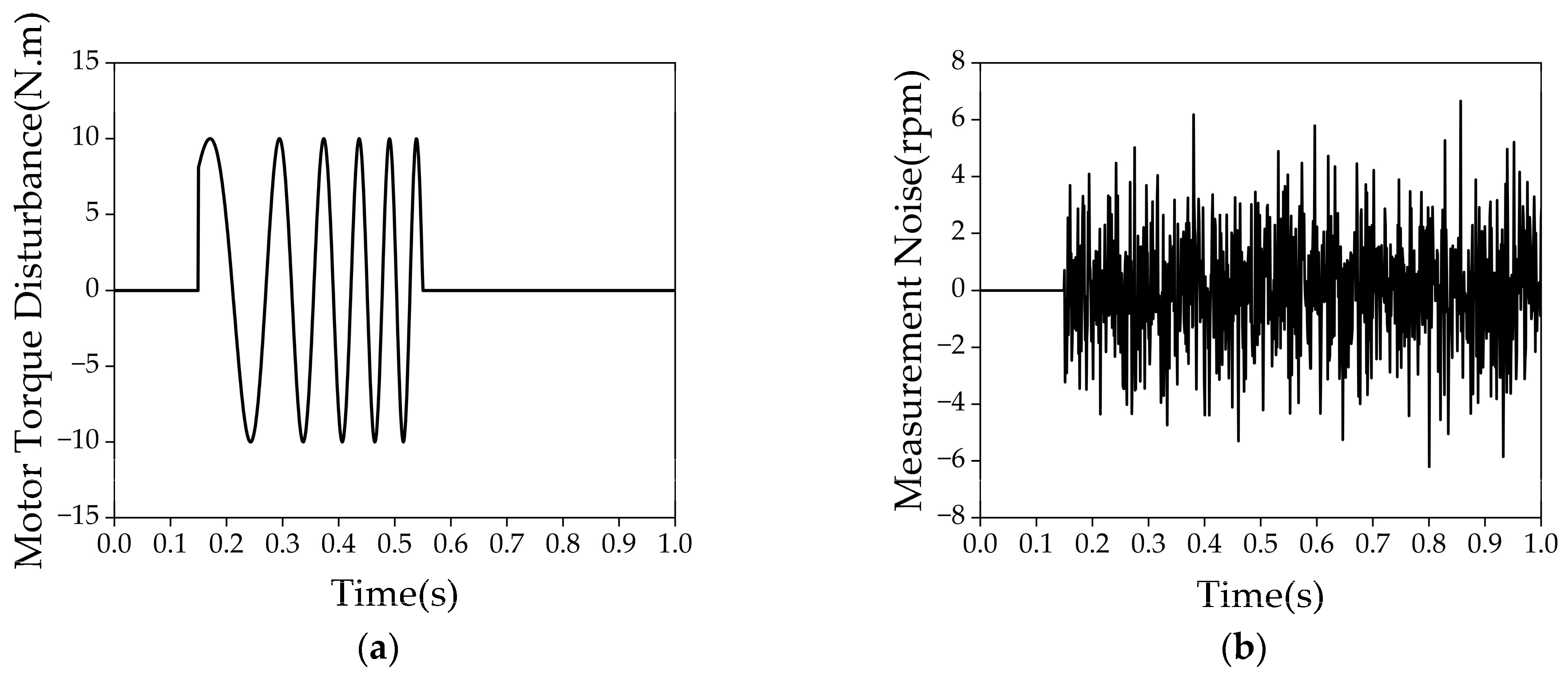
  • Disturbance variables f are introduced into the model, where the disturbances consist of two main components. One is the external disturbance, primarily from the transient engine output torque that cannot be measured by sensors. The other is the internal disturbance, arising from changes in damping torque caused by uncertainties in the damper, gears, and factors such as friction and lubrication conditions. These factors are difficult to describe using the observation-oriented mathematical model. Therefore, by introducing the disturbance variable f, the model’s prediction accuracy is improved to some extent.
    The simplified model is shown in Figure 7.
Therefore, the mathematical model oriented towards observation is expressed as:
J I C E = J 1 + J 2 J I S G = J 3 + J 4 i 2 + J 5 + J 6 1 K e q = 1 K 12 + 1 K 23 + 1 K 34 + 1 K 45 + i 2 K 56
θ ˙ s h f = ω I C E ω I S G i J I C E ω ˙ I C E + K e q θ s h f = f J I S G ω ˙ I S G K e q θ s h f i = T I S G
where ω I C E and ω I S G represent the rotational speeds of the engine and motor, respectively, and θ s h f represents the torsional angle of the drivetrain.
Based on the observation-oriented mathematical model, the system state is selected as x = [ ω I C E , ω I S G , θ s h f ] T , the input is u = [ T I S G ] , and the output is y = [ ω I C E , ω I S G ] T . The Rquation (6) are then rearranged into state-space form as follows:
x ˙ = A x + B u + H f y = C x
where A = 0 0 K e q J I C E 0 0 K e q J I S G i 1 1 i 0 , B = 0 1 J I S G 0 , H = 1 J I C E 0 0 , C = 0 1 0 0 0 1 .

2.2.2. Design of the Extended State Kalman Filter

To effectively estimate both the system states and external disturbances, this paper proposes a disturbance observer based on the Kalman filtering framework, targeting vibration suppression during the engine start-up process in hybrid powertrains. To incorporate disturbance estimation, the system state in the control model is augmented to x f = [ x   f ] T , resulting in the following state-space representation for the observer model:
x ˙ f = A f x f + B f u
where A f = A I 0 0 , B f = B 0 .
The state-space model is discretized using the forward Euler method, yielding the following discrete-time representation:
x k + 1 = A d f x k + B d f u k y ( k ) = C d f x ( k )
In this expression, the discretized coefficients are given as follows:
A d f = I + T s A f B d f = T s B f C d f = C
where T s is the sampling period.
In practical engineering problems, the engine speed ω I C E m e a n   and motor speed ω I S G m e a n   can be measured using sensors. Therefore, the measurement state is given by z ( k ) = [ ω I C E m e a n   ω I S G m e a n ] T . The Kalman filter is then used to estimate the system state x f ( k ) at the k-th time step, resulting in the observed system state x ^ ( k ) and disturbance state f ^ ( k ) . The five iterative equations for this process are:
x ^ f ( k + 1 ) = A d f x ^ f ( k ) + B d f u ( k ) P ( k ) = A d f P ( k 1 ) A d f T + Q K ( k ) = P ( k ) G T G P ( k ) G T + R x ^ f ( k ) = x ^ f ( k ) + K ( k ) [ z ( k ) H x ^ f ( k ) ] P ( k ) = [ I K ( k ) L ] P ( k )
where x ^ f ( k ) = x ^ ( k ) f ^ ( k ) = ω ^ I C E ( k ) ω ^ I S G ( k ) θ ^ s h f ( k ) f ^ ( k ) is the posterior estimate of the system state at the k -th time step; x ^ f ( k ) is the prior estimate of the system state at the k -th time step; P ( k ) and P ( k ) represent the prior and posterior covariance matrices at the k -th time step, respectively; Q and R are the covariance matrices of system noise and measurement noise, respectively; K ( k ) is the observer gain at the k -th time step, and L = [ I   0 ] .
After using Equations (10)–(12) to compute the posterior estimate of the torsion angle θ ^ s h f ( k ) , the corresponding torsion damper torque T ^ s h f ( k ) can be further calculated to facilitate subsequent resonance feature extraction and analysis. The specific calculation formula is as follows:
T ^ s h f ( k ) = K e q θ ^ s h f ( k )

2.3. Transient Frequency Domain Feature Identification

When the main harmonic frequency of the engine excitation torque matches the inherent frequency of the driveline system, resonance is likely to occur. This results in significant torsional vibrations in the torsional damper, leading to torsional vibration issues. Therefore, identifying the resonance characteristics in the torsional damper torque signal is crucial not only for locating regions where resonance might occur but also for providing key frequency-domain information to the control system, enabling targeted adjustments to the control inputs. The torsional damper torque signal, as a typical non-stationary signal, exhibits frequency components that continuously adjust with changes in engine speed. Traditional time-domain and frequency-domain analysis methods struggle to accurately capture these complex signal variations. However, continuous wavelet transform (CWT), through multi-scale analysis, can adaptively select different time and frequency resolutions, effectively addressing the abrupt frequency changes and non-stationary characteristics present in the signal. This makes CWT particularly suitable for analyzing torsional vibration signals in the driveline of hybrid powertrain systems, revealing the fine-grained variations in both time and frequency domains.
The definition of the continuous wavelet transform is as follows:
W τ , s = x t · 1 s ψ t τ s d t
where τ is the translation parameter, s is the scale factor, ψ is the wavelet function, and x ( t ) represents the torsional damper torque signal.
Based on the time-domain characteristics of the torsional damper torque signal shown in Figure 5e, it exhibits a quasi-sinusoidal structure in certain localized regions. In this study, the Morlet wavelet is selected as the mother wavelet function for the continuous wavelet transform, and its mathematical expression is given by:
ψ m o r l e t   x = π 1 / 4 exp i ω 0 x exp x 2 2
where ω 0 is the central frequency, which determines the frequency of the sinusoidal component.
The torsional vibration feature identification process during each engine start-up in this study is as follows:
  • The rotational speeds of the engine and motor are collected, and the torsional damper torque signal is obtained using an ESKF observer.
  • During the engine start-up process, the torsional damper torque signal is sampled in real time at a fixed rate until the start-up process is complete.
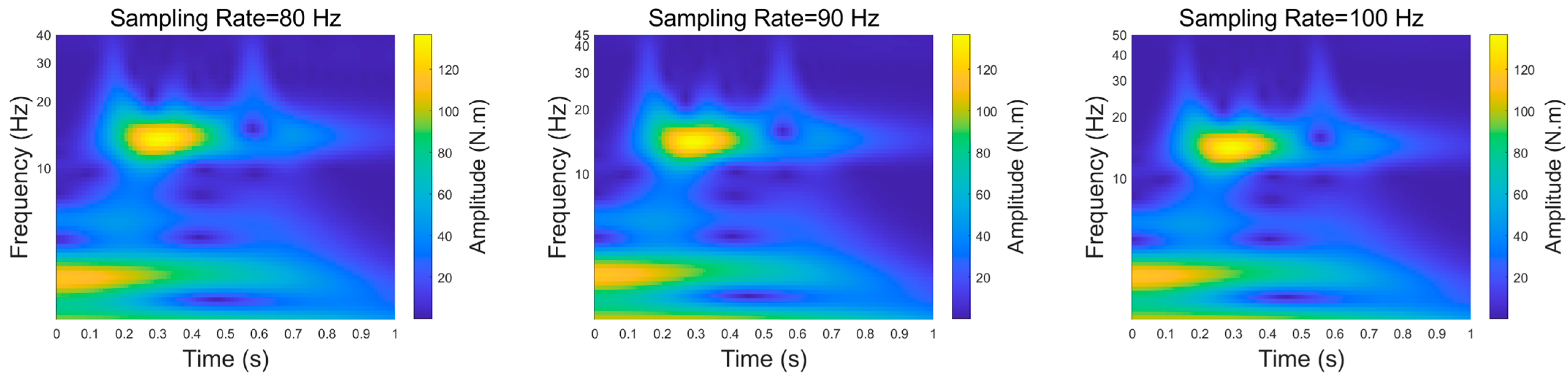
  • In the idle period following engine start-up, the CWT is applied to extract the resonance features from the torque signal. This approach alleviates the computational load of online algorithms while ensuring accurate identification of torsional vibration characteristics.
  • The extracted amplitude-frequency features are then utilized in parameter learning algorithms and subsequent torsional vibration suppression algorithms to optimize system performance.

2.4. Partition-Based Hybrid Parameter Learning Algorithm

Based on the CWT, this study accurately extracts the resonance frequency information from the torsional damper torque signal during the engine start-up process in a hybrid powertrain system, thereby providing an intuitive reflection of the drivetrain’s dynamic characteristics under transient conditions. However, critical parameters in the system model—such as stiffness and inertia—are significantly influenced by operating conditions and nonlinear disturbances, exhibiting strong uncertainty and time variability. These parameter perturbations affected the estimation accuracy of the torsional damper torque, with changes in RMSE values shown in Figure 8. Therefore, conventional fixed-parameter observers struggle to accurately capture the actual dynamic behavior of the system, compromising both the accuracy and robustness of the observer model.
To improve the adaptability and estimation accuracy of the observer under transient conditions, this paper proposes a partitioned parameter self-learning algorithm. The basic procedure of the method is as follows:
  • Perform time-frequency analysis on the torque signal of the torsional damper using CWT to extract resonance frequency features.
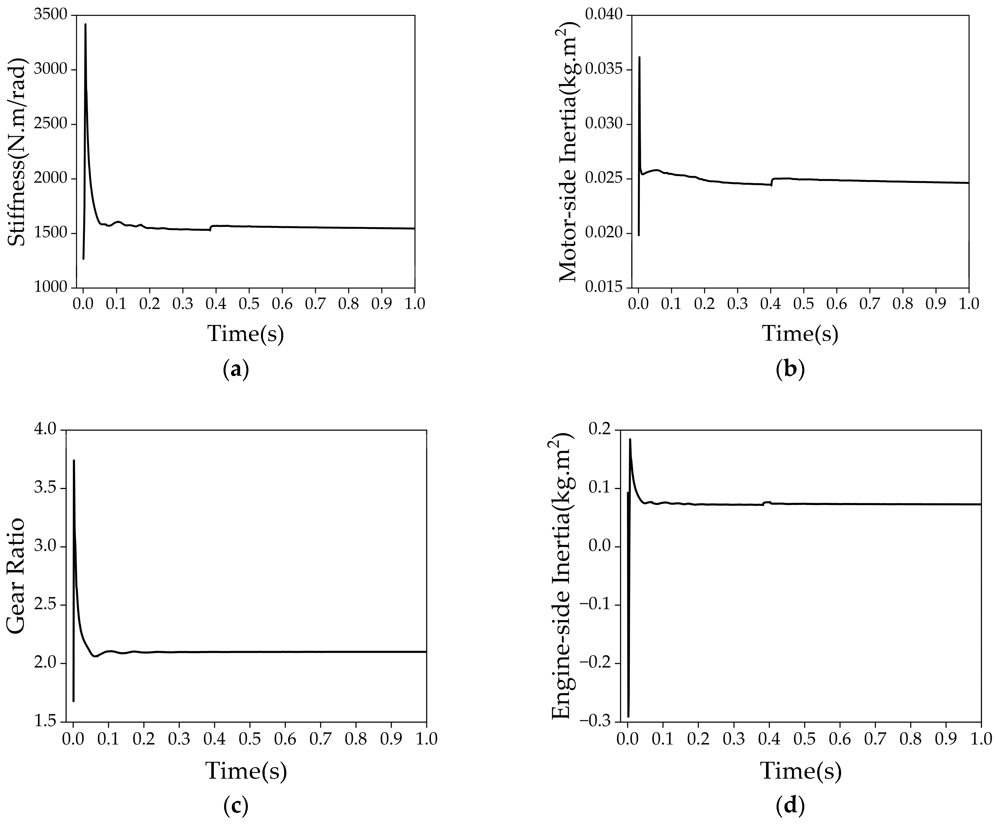
  • Based on the torsional dynamics model, apply the least squares method to estimate three key dynamic parameters: equivalent stiffness, motor-side rotational inertia, and transmission ratio.
  • Combine the parameters obtained in Step 2 with the resonance frequency identified via CWT and substitute them into the system’s natural frequency model to further estimate the engine-side rotational inertia.
This method enables timely updating of model parameters in cases of operating condition variations or nonlinear disturbances, thereby enhancing the observer’s ability to track system states and improve estimation accuracy during transient processes. Moreover, the parameters identified during the current start-up event can serve as initial references for subsequent events, enabling continuous self-adaptive adjustment and optimization of the model.
In the model described by Equation (6), the torsional angle θ s h f = φ 2 φ 3 i   cannot be measured directly, which poses a challenge for the online learning algorithm. Therefore, the model is differentiated once to obtain:
J I C E ω ¨ I C E + K e q ω I C E ω I S G i T ˙ I C E = 0 J I S G ω ¨ I S G K e q i ω I C E ω I S G i T ˙ I S G = 0
In practice, the measured data are typically discrete-time signals. To enable numerical computation and improve identification accuracy, the above dynamic equations are discretized. A difference operator is introduced and defined as follows:
Z k ( x ) = x k 2 x k 1 + x k 2 R k ( x ) = x k x k 2
where the superscript k denotes the discrete time step, and x represents an arbitrary time-series signal (e.g., ω I C E or ω I S G ).
Based on the operator definition above and assuming a sampling period of t , the first- and second-order derivatives can be approximated using the central difference method as follows:
x ˙ k x k x k 2 2 t R k ( x ) 2 t x ¨ k x k 2 x k 1 + x k 2 t 2 Z k ( x ) t 2
According to the above definitions, Equation (15) can be expressed at discrete time step k as:
2 J 1 t Z k ( ω I C E ) + K e q R k ( ω I C E ) α R k ( ω I S G ) = R k ( T I C E ) 2 J 2 t Z k ( ω I S G ) α R k ( ω I C E ) + β R k ( ω I S G ) = R k ( T I S G )
In the equation, α = K e q / i and β = K e q / i 2 .
Considering that the engine-side torque T I C E is unmeasured and thus lacks independent constraints during the learning process, it cannot be directly identified. Therefore, this study utilizes only the ISG-side equation to identify the parameters J I S G ,     K e q and i . To facilitate parameter identification using the least squares method, the above equation is reformulated into a standard matrix regression form:
g ( k ) θ = p ( k )
Specifically defined as:
g ( k ) = [ 2 Z k ( ω I S G ) t   R k ( ω I C E )       R k ( ω I S G ) ]
θ = J I S G α β
p ( k ) = R k ( T I S G )
During the engine start-up process, the sampled data with a window size of N are sequentially stacked to form the extended matrix equation:
g ( 1 ) g ( 2 ) g ( N ) θ = p ( 1 ) p ( 2 ) p ( N )
Denoted as:
G θ = P
The parameters can be identified by solving the above matrix equation using the standard least squares method:
θ = ( G T G ) 1 G T P
On the other hand, since the engine-side torque TICE is unmeasured, the engine inertia J I C E cannot be directly identified using the above matrix equation. To address this, this study further proposes the use of the drivetrain’s inherent resonance frequency model for supplementary identification.
Based on the dynamic characteristics of the drivetrain, the natural frequency ω n of the drivetrain satisfies:
ω n 2 = K e q J I C E + i 2 * J I S G
During the identification process of the parameters J I S G , K e q and i , the main resonance frequency ω n of the torsional damper torque signal during the engine start-up phase is extracted using CWT. By substituting this into Equation (25), the following result can be directly obtained:
J I C E = K e q ω n 2 i 2 * J I S G
In this way, the engine inertia parameter can be obtained, thus overcoming the difficulty of measuring the engine-side torque and enabling online learning of all parameters.

3. Results

3.1. Model Validation

After completing the modeling and parameter calibration, the hybrid powertrain system was validated by comparing simulation results with test bench measurements, as shown in Figure 9. The comparison results indicate that the simulated outputs of engine speed and motor speed exhibit high consistency with the measured data, with relative errors consistently maintained within 4%, thereby verifying the accuracy of the developed powertrain model.
The subsequent analysis and validation of the torsional vibration characteristics during the engine start-up process of the hybrid powertrain system were all conducted based on the validated simulation model. Due to current limitations in experimental resources, it is not yet possible to obtain stronger empirical support from a physical hybrid powertrain test bench. Therefore, this study primarily relies on simulation results for algorithm validation.

3.2. Observer Performance Validation

To verify the applicability of the proposed ESKF method, this study selects a robust observer designed based on linear matrix inequalities (LMI) as a comparative scheme. The LMI-based observer enhances robustness against modeling errors and external disturbances by imposing optimized constraints and theoretically exhibits certain stability under parameter uncertainty. However, this method relies heavily on accurate modeling of the system structure and parameters, and its gain design is typically performed offline, lacking the capability for real-time adaptation. As a result, its applicability is limited under structural transitions commonly found in hybrid powertrain systems.
In contrast, the proposed ESKF method is based on the concept of an extended state observer, where disturbance terms and model uncertainties are explicitly introduced into the system state vector. A standard linear Kalman filter is then employed to jointly estimate both system states and disturbances, offering stronger dynamic modeling capability and better real-time adaptability. To compare the performance of the two observers, RMSE is used as the primary evaluation metric for estimation accuracy. In addition, a disturbance injection test is designed to assess the robustness of the ESKF method under external interference.
The simulation results shown in Figure 10 indicate that the ESKF provides significantly better estimation results than the LMI filter. Specifically, the RMSE of the ESKF observer is 2.08 N·m, while the RMSE of the LMI filter is 7.3 N·m, representing a 71.51% improvement in the performance of the ESKF observer.
To test the robustness of the ESKF observer proposed in this study, interference torque, as shown in Figure 11a, is added to the motor torque. Additionally, noise, as shown in Figure 11b, is introduced into the motor speed measurement to simulate the measurement error of the speed sensor.
The torsional damper torque estimation results are shown in Figure 12. As can be seen, the torque estimation from the LMI observer is significantly affected by input disturbances and measurement noise, resulting in an RMSE of 10.16 N·m. The presence of input disturbances and measurement noise prevents the LMI observer from effectively handling the system’s nonlinear characteristics and disturbances, leading to deviations in the estimation and making it unable to accurately reflect the actual torque. In contrast, the ESKF, by introducing the extended state approach, can dynamically update the system state estimates in the presence of input disturbances and measurement noise, thus maintaining a higher estimation accuracy. The RMSE of the ESKF is 2.28 N·m, which represents a 77.56% improvement in estimation performance compared to the LMI observer. This demonstrates that the ESKF can effectively overcome the effects of disturbances and noise, providing a more accurate torque estimate.
In summary, the introduction of the extended state allows the ESKF to not only estimate the system states but also simultaneously estimate disturbances within the system, significantly enhancing its ability to observe the torsional damper torque under complex disturbances. This advantage gives the ESKF superior robustness compared to the LMI observer in dynamic environments, providing more accurate estimation support for subsequent torsional vibration resonance feature identification.
In addition, according to the optimal estimation theory of linear systems, the error dynamics of a Kalman filter are asymptotically stable under the conditions of system observability and positive-definite noise covariance [42]. Since the extended state model adopted in the proposed ESKF maintains system observability, this stability conclusion also applies to the estimation structure used in this study.

3.3. Parameter Learning Algorithm Validation

Figure 13 illustrates the parameter learning process during the start-up phase with 20% disturbance applied to each structural parameter. As shown in the figure, the parameters change rapidly during the start-up process and gradually approach their actual values. Approximately 0.5 s into the process, the parameters stabilize and eventually converge. The convergence results are presented in Table 3. The parameters learned using the torsional dynamics model achieved an accuracy of over 96%. However, due to errors in the inherent frequency model and resonance feature identification, the accuracy of the engine inertia was 92.85%, which still meets the control requirements. These results demonstrate that the proposed partition-based hybrid learning strategy successfully achieved effective parameter identification.
Figure 14 shows the observation results of the torsional damper torque signal under both fixed and adaptive parameter conditions. As can be seen, after a 20% disturbance is applied to each parameter, the fixed-parameter observer model fails to accurately estimate the torsional damper torque signal, with an RMSE of 15.99 N.m. In contrast, after applying the parameter self-learning algorithm, the observer model with adaptive parameter updates is able to closely track the actual torque values, reducing the RMSE to 2.36 N.m. The experimental results demonstrate that the parameter self-learning algorithm significantly improves the estimation accuracy of the observer model under structural parameter disturbances.

3.4. Validation of Transient Frequency-Domain Feature Identification

In the wavelet transform process, frequency resolution is a key factor affecting the accuracy and effectiveness of the results. It determines the ability to identify different frequency components of the signal and directly impacts the extraction of resonance frequencies. If the frequency resolution is too low, the frequency range will be too wide, making it difficult to accurately identify the resonance frequency. On the other hand, if the frequency range is too narrow, computational resources may be wasted. Therefore, it is crucial to set the frequency range properly. In CWT, the frequency range is determined by the VPO parameter. A lower VPO value results in a wider frequency range, while a higher VPO value narrows the frequency range. This section analyzes the frequency range under different VPO settings and, by examining the relationship between peak frequencies, adjacent frequencies, and actual natural frequencies, identifies the optimal VPO value to improve feature identification accuracy. Figure 15 shows the effect of torsional resonance feature identification as the VPO value changes from 1 to 45. By comparing the results under different VPO settings and evaluating the variation trends of peak and adjacent frequencies, the optimal balance between accuracy and computational resources is determined.
Figure 16 shows the peak frequency and its adjacent frequencies obtained through wavelet transform for different VPO values and further determines the corresponding frequency range size. From the figure, it can be seen that when the VPO value is low, the frequency range is wide, with the widest range being [6.25, 12.5] Hz, resulting in a frequency range of 6.25 Hz. As the VPO value increases to 15, the peak frequency is 14.3587 Hz. With further increases in the VPO value, the peak frequency remains unchanged, while only the adjacent frequencies gradually change. The frequency range changes from [14.3587, 15.0378] Hz at VPO = 15 to [14.3587, 14.5816] Hz at VPO = 45, with the range size reducing from 0.6791 Hz to 0.2229 Hz. Considering that 0.6791 Hz is already less than 5% of the system’s natural frequency of 14.53 Hz, and the feature frequency identified at VPO = 15 is 14.698 Hz, which deviates from the actual natural frequency by only 1.1%, VPO = 15 is determined to be the optimal choice when considering both the accuracy of feature extraction and memory resource usage.
In wavelet transform applications, the choice of sampling rate plays a crucial role in both the accuracy of the results and the consumption of computational resources. A higher sampling frequency allows for more precise capture of the time-frequency details of the signal, improving the analysis resolution, but it also increases computational complexity and memory usage. Therefore, although a high sampling frequency enhances frequency resolution and the ability to capture instantaneous frequency changes, it also imposes a greater computational burden. This section compares the wavelet transform results of the torsional damper torque signal at different sampling frequencies through simulation experiments, ultimately determining the optimal sampling frequency to strike a balance between accuracy and computational efficiency. Figure 17 shows the torsional vibration resonance feature identification results at different sampling rates. By comparing the identification results at different sampling rates and evaluating the trends in peak frequencies, adjacent frequencies, and their corresponding frequency ranges, the goal is to find the optimal balance point between precision and computational efficiency.
Figure 18 shows the peak frequencies and their adjacent frequencies obtained through wavelet transform at different sampling rates and further determines the corresponding frequency range. From the figure, it can be seen that when the sampling rate is below 40 Hz, there is a significant difference between the peak frequency and the natural frequency, which is primarily due to frequency distortion caused by low sampling rates. When the sampling rate reaches 50 Hz, the identified peak frequency is 14.3587 Hz, and the subsequent frequency identification changes very little. At the same time, since the VPO value remains constant, the frequency range also stays consistent. Therefore, considering both the accuracy of feature extraction and computational efficiency, a sampling rate of 50 Hz is determined to be the optimal choice.

3.5. Limitations and Future Work

Although the feature extraction method proposed in this study performs well in the simulation environment, it still has certain limitations. First, the model is developed based on linear assumptions, without fully accounting for the nonlinear dynamic characteristics of the system, which may affect estimation accuracy under extreme operating conditions. Second, the algorithm has not yet been deployed or tested on a hardware-in-the-loop (HIL) platform, making it difficult to comprehensively evaluate its real-time performance and robustness in embedded environments. Furthermore, the overall system has not been validated through real vehicle or test bench experiments, and its adaptability under actual operating conditions remains to be verified. Future work will focus on nonlinear modeling, HIL platform deployment, and physical experiment validation to enhance the engineering applicability and reliability of the proposed method.

4. Discussion

Compared with conventional single-source powertrains, hybrid electric vehicles exhibit more complex torsional vibration issues due to the presence of multiple excitation sources and more intricate drivetrain structures, which increases the difficulty of vibration suppression control. In terms of vibration suppression performance evaluation, existing studies mainly rely on time-domain feature analysis, using quantitative indicators such as impact intensity and engine torque fluctuation to describe the torsional response [6,16]. However, during the engine start-up process of an HEV, the excitation frequency changes rapidly with engine speed, resulting in pronounced non-stationary vibration characteristics. Traditional time-domain methods are limited in their ability to capture transient features during the dynamic variation in excitation frequency, and they also fail to reflect the system’s energy response in critical resonance frequency bands. To improve the controller’s ability to identify and suppress torsional vibration, this paper focuses on observing and extracting transient features from the torque at the torsional damper, which serves as the actual excitation within the system. By modeling unmodeled components such as engine torque as extended disturbance states and computing the observer gain via a Kalman filter, the observed torque signal is subsequently processed using wavelet transform to identify transient torsional frequency-domain features. The extracted frequency information serves as a critical input for the natural frequency learning model, while the frequency-domain amplitude features can be used as design references for controller performance metrics.
On the one hand, to improve modeling efficiency, the drivetrain connection structures are simplified as linear systems with constant stiffness, damping, and inertia parameters, neglecting nonlinearities and operating condition variations. Although the proposed model captures the primary torsional characteristics and dynamic trends of the drivetrain, its accuracy may degrade under extreme operating conditions. Therefore, a parameter-partitioned learning algorithm is introduced to enable online adjustment and compensation of key dynamic parameters, thereby enhancing the model’s adaptability to operating condition changes and its robustness against disturbances, ultimately improving estimation accuracy. From a structural adaptability perspective, the proposed method is based on modeling key inertia nodes along the drivetrain path without relying on a specific powertrain topology, thus offering a degree of scalability. For series or plug-in hybrid systems, although the control strategies for power sources may differ, the torsional excitation characteristics persist. Therefore, the proposed method can be extended to other hybrid powertrain configurations by modifying the excitation modeling and disturbance mapping processes. Future research may further adapt disturbance modeling approaches and parameter learning strategies to fit various hybrid architectures, enabling the development of cross-platform estimation systems. Furthermore, the proposed torque estimation method, which integrates extended state observation with wavelet-based feature extraction, exhibits strong structural decoupling and algorithmic generality. It enables disturbance estimation and torsional feature identification in hybrid powertrains without relying on high-precision torque sensors, demonstrating strong potential for engineering applications.
On the other hand, wavelet transform, as a representative time-frequency analysis tool, has been widely applied in feature extraction and disturbance identification for non-stationary signals, demonstrating excellent performance in vehicle vibration analysis and fault diagnosis. In this study, CWT was performed on approximately 1 s of engine start-up signal data (around 50 sampling points) at a sampling rate of 50 Hz. Resonance features were identified during the subsequent idle phase, validating the feasibility of the proposed method. Although real-time execution has not yet been implemented, considering the algorithm’s computational complexity and real-time requirements, it is expected that the method can be deployed on a rapid prototyping platform such as dSPACE, which has already been applied in real-time signal processing tasks including wavelet transform [43,44]. The CWT used in this study offers high time-frequency resolution but requires convolution across multiple continuous scales, resulting in high computational demands and increased hardware requirements. In contrast, DWT extracts features at discrete scales through multiscale decomposition, thereby reducing computational and memory overhead, making it more suitable for embedded real-time applications. While DWT may offer slightly lower frequency resolution compared to CWT, its efficiency and real-time performance provide practical advantages in engineering scenarios. Future work will further evaluate the adaptability of both methods across different application contexts. In addition, lightweight neural networks based on the Transformer architecture have shown great potential in sequential modeling and noise-robust analysis. Given the short signal duration and locally concentrated features in this study, a compact Transformer model could be developed in future work to learn the distribution of wavelet-domain features. Coupled with noise suppression mechanisms, this approach may further enhance the robustness and real-time performance of the estimation algorithm. Reinforcement learning methods may also be explored to establish input–output mapping strategies for frequency-domain torsional vibration features. Although such research has not yet been conducted due to limitations in sample size and computational resources, future efforts will explore its feasibility using real vehicle data.

5. Conclusions

This paper addresses the issue of torsional vibration induced by drivetrain resonance during engine startup in hybrid power systems. Focusing on the powertrain system of a series–parallel hybrid electric vehicle, a time-varying frequency domain feature identification algorithm for torsional vibration during engine startup is proposed. Specifically, a torsional vibration feature identification method based on disturbance-rejection observation and parameter partition learning is developed to accurately extract torsional vibration characteristics. The main contributions are summarized as follows:
  • Time-domain response and frequency-domain modal analysis of the powertrain system are conducted. When the excitation frequency approaches the natural frequencies of the system, resonance is likely to occur, leading to significant torsional vibrations in the torsional damper torque signal.
  • A six-degree-of-freedom (DOF) rotational dynamic model of the drivetrain is simplified to a two-DOF observer-oriented model under reasonable assumptions. An extended state Kalman filter (ESKF) is constructed by incorporating engine torque and unmodeled disturbances into the augmented state vector, and the observer gain is obtained within a Kalman filtering framework. For validation, an H2-optimal LMI-based observer is designed for performance comparison. To address parameter uncertainty in the system, a parameter partition learning approach is proposed based on sensor layout, the developed two-DOF dynamic model, and modal characteristics. Simulation results show that, under input disturbance and sensor noise, the RMSE of the LMI observer is 10.16 N·m, while the ESKF achieves an RMSE of 22.28 N·m, representing a 77.56% improvement in estimation accuracy. Furthermore, when structural parameters are perturbed by 20%, the fixed-parameter observer model fails to accurately estimate the torsional damper torque, resulting in an RMSE of 15.99 N.m. In contrast, with the integration of the parameter self-learning algorithm, the observer accurately tracks the actual torque variations, reducing the RMSE to 2.36 N.m—a relative improvement of 85.2%. These results verify the effectiveness and robustness of the ESKF and parameter learning strategies in enhancing torque estimation accuracy.
  • The time-varying frequency characteristics of the non-stationary torsional damper torque signal are analyzed. By evaluating the impact of the mother wavelet, voices per octave (VPO), and sampling rate in continuous wavelet transform (CWT), a balance between accuracy, memory usage, and computational efficiency is achieved. Results indicate that the Morlet wavelet demonstrates excellent time-frequency localization. With a VPO of 15 and a sampling rate of 50 Hz, the identified torsional resonance frequency range is [14.3587, 15.0378] Hz, with a peak at 14.698 Hz—only a 1.1% deviation from the actual natural frequency of 14.53 Hz. This confirms the effectiveness of CWT in capturing transient frequency-domain features of non-stationary torque signals. The findings lay a theoretical foundation for subsequent control strategies aimed at torsional vibration suppression and powertrain system optimization.

Author Contributions

Conceptualization, T.Z. and B.L.; methodology, H.X.; software, T.Z. and B.L.; validation, T.Z.; formal analysis, T.Z. and B.L.; data curation, T.Z.; writing—original draft preparation, T.Z.; writing—review and editing, H.X., T.Z. and B.L. All authors have read and agreed to the published version of the manuscript.

Funding

This research was funded by the National Natural Science Foundation of China, grant number 51906174.

Data Availability Statement

The data that support the findings of this study are available from the corresponding author upon reasonable request.

Conflicts of Interest

The authors declare no conflicts of interest.

References

  1. Bellocchi, S.; Klöckner, K.; Manno, M.; Noussan, M.; Vellini, M. On the role of electric vehicles towards low-carbon energy systems: Italy and Germany in comparison. Appl. Energy 2019, 255, 113848. [Google Scholar] [CrossRef]
  2. Liu, Y.; Huang, B.; Yang, Y.; Lei, Z.; Zhang, Y.; Chen, Z. Hierarchical speed planning and energy management for autonomous plug-in hybrid electric vehicle in vehicle-following environment. Energy 2022, 260, 125212. [Google Scholar] [CrossRef]
  3. Chen, Z.; Wu, S.; Shen, S.; Liu, Y.; Guo, F.; Zhang, Y. Co-optimization of velocity planning and energy management for autonomous plug-in hybrid electric vehicles in urban driving scenarios. Energy 2023, 263, 126060. [Google Scholar] [CrossRef]
  4. Ma, S.C.; Xu, J.H.; Fan, Y. Characteristics and key trends of global electric vehicle technology development: A multi-method patent analysis. J. Clean. Prod. 2022, 338, 130502. [Google Scholar] [CrossRef]
  5. Qin, Y.; Tang, X.; Jia, T.; Duan, Z.; Zhang, J.; Li, Y.; Zheng, L. Noise and vibration suppression in hybrid electric vehicles: State of the art and challenges. Renew. Sustain. Energy Rev. 2020, 124, 109782. [Google Scholar] [CrossRef]
  6. Su, Y.; Hu, M.; Huang, J.; Qin, D.; Fu, C.; Zhang, Y. Dynamic torque coordinated control considering engine starting conditions for a power-split plug-in hybrid electric vehicle. Appl. Sci. 2021, 11, 2085. [Google Scholar] [CrossRef]
  7. Wu, H.; Wu, G. Driveline torsional analysis and clutch damper optimization for reducing gear rattle. Shock Vib. 2016, 2016, 8434625. [Google Scholar] [CrossRef]
  8. Pettersson, M.; Nielsen, L.; Hedström, L.G. Transmission-torque control for gear shifting with engine control. SAE Trans. 1997, 106, 1265–1275. [Google Scholar]
  9. Pettersson, M.; Nielsen, L. Gear shifting by engine control. IEEE Trans. Control Syst. Technol. 2000, 8, 495–507. [Google Scholar] [CrossRef]
  10. Wang, B.; Zhang, Z.; Yu, H.; Cheng, H.; Wang, C. Analysis and Control on Vibration Resulted from Engine Start of Hybrid Electric Vehicle. Automot. Eng. 2019, 41, 184–190. [Google Scholar]
  11. Park, J.; Choi, S.; Oh, J.; Eo, J. Adaptive torque tracking control during slip engagement of a dry clutch in vehicle powertrain. Mech. Mach. Theory 2019, 134, 249–266. [Google Scholar] [CrossRef]
  12. Shi, J.; Li, L.; Wang, X.; Liu, C. Robust output feedback controller with high-gain observer for automatic clutch. Mech. Syst. Signal Process. 2019, 132, 806–822. [Google Scholar] [CrossRef]
  13. Geng, X.; Liu, W.; Liu, X.; Wen, G.; Xue, M.; Wang, J. Optimal Torque Control of the Launching Process with AMT Clutch for Heavy-Duty Vehicles. Machines 2024, 12, 363. [Google Scholar] [CrossRef]
  14. Gao, B.; Hong, J.; Qu, T.; Yu, S.; Chen, H. An output regulator with rejection of time-varying disturbance: Experimental validation on clutch slip control. IEEE Trans. Control Syst. Technol. 2019, 28, 1158–1167. [Google Scholar] [CrossRef]
  15. Morandin, M.; Bolognani, S.; Faggion, A. Active torque damping for an ICE-based domestic CHP system with an SPM machine drive. IEEE Trans. Ind. Appl. 2015, 51, 3137–3146. [Google Scholar] [CrossRef]
  16. Cai, Y.; Dou, L.; Chen, L.; Shi, D.; Wang, S.; Zhu, Z. Research on Coordinated Control of Hybrid Electric Vehicle Based on Compensation Sliding Mode Control. Automot. Eng. 2020, 42, 431–438. [Google Scholar]
  17. Tang, X.; Zhang, D.; Liu, T.; Khajepour, A.; Yu, H.; Wang, H. Research on the energy control of a dual-motor hybrid vehicle during engine start-stop process. Energy 2019, 166, 1181–1193. [Google Scholar] [CrossRef]
  18. Su, Y.; Su, L.; Hu, M.; Qin, D.; Fu, C.; Yu, H. Modeling and dynamic response analysis of a compound power-split hybrid electric vehicle during the engine starting process. IEEE Access 2020, 8, 186585–186598. [Google Scholar] [CrossRef]
  19. Geng, Y.; Chen, R.; Yang, S.; Zhou, T.; Shao, Y.; Dai, W. Research on Mode Switching Vibration Suppression Strategy of Hybrid Electric Vehicle With Active Motor Response. IEEE Trans. Transp. Electrif. 2024, 11, 5470–5483. [Google Scholar] [CrossRef]
  20. Park, J.; Choi, S.; Oh, J.; Eo, J. Adaptive slip engagement control of a wet clutch in vehicle powertrain based on transmitted torque estimation. Mech. Syst. Signal Process. 2022, 171, 108861. [Google Scholar] [CrossRef]
  21. Lin, C.; Sun, S.; Yi, J.; Walker, P.; Zhang, N. Accelerated adaptive super twisting sliding mode observer-based drive shaft torque estimation for electric vehicle with automated manual transmission. IET Intell. Transp. Syst. 2019, 13, 160–167. [Google Scholar] [CrossRef]
  22. Na, J.; Chen, A.S.; Herrmann, G.; Burke, R.; Brace, C. Vehicle engine torque estimation via unknown input observer and adaptive parameter estimation. IEEE Trans. Veh. Technol. 2017, 67, 409–422. [Google Scholar] [CrossRef]
  23. Zhou, B.; Zhang, J.; Gao, J.; Yu, H.; Liu, D. Clutch pressure estimation for a power-split hybrid transmission using nonlinear robust observer. Mech. Syst. Signal Process. 2018, 106, 249–264. [Google Scholar] [CrossRef]
  24. Oh, J.J.; Choi, S.B.; Kim, J. Driveline modeling and estimation of individual clutch torque during gear shifts for dual clutch transmission. Mechatronics 2014, 24, 449–463. [Google Scholar] [CrossRef]
  25. Xu, D.; Zhang, J.; Zhou, B.; Yu, H. Robust hierarchical estimator of clutch torques for a compound power-split hybrid electric vehicle. Mech. Syst. Signal Process. 2019, 134, 106320. [Google Scholar] [CrossRef]
  26. Li, M.; Zhao, Z.; Fan, J.; Gao, J. Estimation of transmission input & output shaft torque and drive wheel speed for compound power split powertrain based on unknown input observer. IEEE Trans. Veh. Technol. 2020, 69, 4883–4893. [Google Scholar]
  27. Kim, S.; Lee, H.; Kim, J.; Park, G. Online adaptive identification of clutch torque transmissibility for the drivability consistency of high-performance production vehicles. Control Eng. Pract. 2024, 147, 105926. [Google Scholar] [CrossRef]
  28. Mousavi, M.S.R.; Alizadeh, H.V.; Boulet, B. Estimation of synchromesh frictional torque and output torque in a clutchless automated manual transmission of a parallel hybrid electric vehicle. IEEE Trans. Veh. Technol. 2016, 66, 5531–5539. [Google Scholar] [CrossRef]
  29. Mousavi, M.S.R.; Boulet, B. Dynamical Modeling and Optimal State Estimation Using Kalman-Bucy Filter for a Seamless Two-Speed Transmission for Electric Vehicles. In Proceedings of the 23rd Mediterranean Conference on Control and Automation (MED), Torremolinos, Spain, 16–19 June 2015. [Google Scholar]
  30. Xue, Q.; Zhang, X.; Chen, H.; Yue, M.; Teng, T.; Yu, J. Dynamic coordinated control strategy of a dual-motor hybrid electric vehicle based on clutch friction torque observer. Heliyon 2024, 10, e27255. [Google Scholar] [CrossRef]
  31. Hao, H.; Lu, T.; Zhang, J.; Ding, W. Investigation on adaptive method of torque characteristic in dual clutch transmission during launch phase. Proc. Inst. Mech. Eng. Part K J. Multi-Body Dyn. 2020, 234, 568–584. [Google Scholar] [CrossRef]
  32. Zhao, Z.; He, L.; Yang, Y.; Wu, C.; Li, X.; Hedrick, J.K. Estimation of torque transmitted by clutch during shifting process for dry dual clutch transmission. Mech. Syst. Signal Process. 2016, 75, 413–433. [Google Scholar] [CrossRef]
  33. Liu, D.; Cheng, W.; Wen, W. Rolling bearing fault diagnosis via STFT and improved instantaneous frequency estimation method. Procedia Manuf. 2020, 49, 166–172. [Google Scholar] [CrossRef]
  34. Zhang, Q.; Deng, L. An intelligent fault diagnosis method of rolling bearings based on short-time Fourier transform and convolutional neural network. J. Fail. Anal. Prev. 2023, 23, 795–811. [Google Scholar] [CrossRef]
  35. Xiang, C.; Ren, Z.; Shi, P.; Zhao, H. Data-Driven Fault Diagnosis for Rolling Bearing Based on DIT-FFT and XGBoost. Complexity 2021, 2021, 4941966. [Google Scholar] [CrossRef]
  36. Chin, C.H.; Abdullah, S.; Ariffin, A.K.; Singh, S.S.K.; Arifin, A. A review of the wavelet transform for durability and structural health monitoring in automotive applications. Alex. Eng. J. 2024, 99, 204–216. [Google Scholar] [CrossRef]
  37. Verstraete, D.; Ferrada, A.; Droguett, E.L.; Meruane, V.; Modarres, M. Deep learning enabled fault diagnosis using time-frequency image analysis of rolling element bearings. Shock Vib. 2017, 2017, 5067651. [Google Scholar] [CrossRef]
  38. Chen, L.; Shi, W.; Chen, Z. Modeling of idle speed transmission based on unit modeling method and performance comparison of various torsional dampers. J. Cent. South Univ. (Sci. Technol.) 2020, 51, 842–852. [Google Scholar]
  39. Hu, Y.; Yang, F.; Du, L.; Zhang, J.; Ouyang, M. A novel method to actively damp the vibration of the hybrid powertrain by utilizing a flywheel integrated-starter-generator. IEEE Access 2020, 8, 147045–147058. [Google Scholar] [CrossRef]
  40. Zhong, B.; Hou, Z.; Liu, R. PID Control on the Torsional Vibration of an Auxiliary Power Unit During Starting. Automot. Eng. 2018, 40, 143–149. [Google Scholar]
  41. Wang, F.; Ye, P.; Xu, X.; Cai, Y.; Ni, S.; Que, H. Novel regenerative braking method for transient torsional oscillation suppression of planetary-gear electrical powertrain. Mech. Syst. Signal Process. 2022, 163, 108187. [Google Scholar] [CrossRef]
  42. Anderson, B.D.; Moore, J.B. Optimal Filtering; Prentice-Hall: Englewood Cliffs, NJ, USA, 1979; pp. 105–115. [Google Scholar]
  43. Ibrahim, M.; Jemei, S.; Wimmer, G.; Steiner, N.Y.; Kokonendji, C.C.; Hissel, D. Selection of mother wavelet and decomposition level for energy management in electrical vehicles including a fuel cell. Int. J. Hydrog. Energy 2015, 40, 15823–15833. [Google Scholar] [CrossRef]
  44. Yan, M.; Li, M.; He, H.; Peng, J.; Sun, C. Rule-based energy management for dual-source electric buses extracted by wavelet transform. J. Clean. Prod. 2018, 189, 116–127. [Google Scholar] [CrossRef]
Figure 1. Algorithm framework diagram.
Energies 18 02847 g001
Figure 2. Series–parallel hybrid powertrain configuration diagram.
Energies 18 02847 g002
Figure 3. Simplified equivalent model of the drivetrain shaft system.
Energies 18 02847 g003
Figure 4. Torsional damper stiffness characteristics curve.
Energies 18 02847 g004
Figure 5. Response curve of the transmission system during engine start: (a) Motor torque; (b) engine torque; (c) motor speed; (d) engine speed; (e) torsional damper and gear torque; (f) torsional damper angular velocity.
Energies 18 02847 g005aEnergies 18 02847 g005b
Figure 6. Relationship between engine excitation frequency and system natural frequency.
Energies 18 02847 g006
Figure 7. Simplified equivalent model of the shafting.
Energies 18 02847 g007
Figure 8. Effects of individual structural parameters on the accuracy of torque estimation.
Energies 18 02847 g008
Figure 9. Comparison of simulation results and actual results of the hybrid power system model: (a) Motor speed; (b) engine speed.
Energies 18 02847 g009
Figure 10. Comparison of torque observation results for torsional damper.
Energies 18 02847 g010
Figure 11. Simulation of external interference: (a) Motor torque disturbance; (b) measurement noise.
Energies 18 02847 g011
Figure 12. Comparison of disturbance rejection in torque observation for torsional damper.
Energies 18 02847 g012
Figure 13. All parameter estimates converge to their true values around t = 0.5 s, demonstrating the effectiveness of the learning algorithm: (a) Stiffness; (b) motor-side inertia; (c) gear ratio; (d) engine-side inertia.
Energies 18 02847 g013
Figure 14. Comparison of torque observation between learning-based algorithm and traditional method for torsional damper.
Energies 18 02847 g014
Figure 15. Wavelet transform feature extraction under varying VPO values: frequency range widens with lower VPO and narrows with higher VPO.
Energies 18 02847 g015
Figure 16. The effect of VPO on torsional vibration frequency characteristics: (a) Characteristic frequency; (b) frequency range.
Energies 18 02847 g016
Figure 17. Wavelet transform analysis under different sampling rates.
Energies 18 02847 g017aEnergies 18 02847 g017b
Figure 18. The impact of sampling rate on torsional vibration frequency characteristics: (a) Characteristic frequency; (b) frequency range.
Energies 18 02847 g018
Table 1. Parameters of key components in the transmission system.
ComponentItemValue
EngineBore/mm78.2
Piston stroke/mm104
Displacement/L2.0
Compression ratio12
Piston mass/g160
Piston skirt length/mm39
Single connecting rod mass/g250
Connecting rod length/mm205
Average shaft diameter/mm50
MotorTorque limit/N.m200
Maximum rotational speed/rpm6000
Motor inertia/kg.m20.02
GearBacklash of drive gear/rad0.0175
Transmission ratio2.1
Drive shaft systemEngine output shaft inertia/kg·m20.0136
Damper primary limit angle/rad0.08
Damper secondary stiffness/N.m/rad1600
Table 2. Natural frequencies of the transmission system.
Torsional Angle Range (rad)First Order
(Hz)
Second Order (Hz)Third Order (Hz)Fourth Order (Hz)Fifth Order (Hz)Sixth Order (Hz)
0–0.080.0813.63984157361098
0.08–100.1314.534134378221135
Table 3. Parameter learning results.
ParametersStiffness Keq (N·m/rad)Motor-Side Inertia JISG (kg·m2)Gear Ratio iEngine-Side Inertia JICE (kg·m2)
True value1584.310.02482.10.078
Identification value1535.770.024462.0990.07242
Identification accuracy (%)96.94%98.63%99.95%92.85%
Disclaimer/Publisher’s Note: The statements, opinions and data contained in all publications are solely those of the individual author(s) and contributor(s) and not of MDPI and/or the editor(s). MDPI and/or the editor(s) disclaim responsibility for any injury to people or property resulting from any ideas, methods, instructions or products referred to in the content.

