Article

Analysis of the Cogging Torque Reduction in Permanent Magnet Generators for a Very Low Wind Speed

1
Department of Electrical Engineering, Institut Teknologi PLN, Jakarta 11750, Indonesia
2
Department of Electrical Engineering, Universiti Tenaga Nasional, Putrajaya 43009, Malaysia
3
Department of Electrical Engineering, Universitas Katolik Indonesia Atma Jaya, Jakarta 12930, Indonesia
*
Author to whom correspondence should be addressed.
Energies 2025, 18(11), 2802; https://doi.org/10.3390/en18112802
Submission received: 15 April 2025 / Revised: 18 May 2025 / Accepted: 22 May 2025 / Published: 28 May 2025

Abstract

:
This research examines the magnet structure’s effect on the performance of permanent magnet generators. The permanent magnet generator’s cogging torque (CT) is one of the characteristics that this article examines. In an electrical machine or permanent magnet generator, CT is a characteristic that can cause unwanted phenomena like vibration and noise. The permanent magnet generator’s magnetic flux density in the core is another crucial factor affecting the machine’s efficiency. The present study introduces this parameter. This study used the finite element method for magnetics to investigate and compare the values of the tangential and normal magnetic flux densities in air gaps. Using the magnet edge slotting technique might decrease the magnetic flux density, the total magnetic flux pouring into the air gap of the permanent magnet generator, and the CT reduction. It is demonstrated that using the two processes of slotting at the magnet edge can result in improved permanent magnet generator performance. The numerical calculation software FEMM 4.2, based on the finite element method, it was used to validate the CT of the permanent magnet generators under examination. It was discovered that the cogging torque of the proposed permanent magnet generator can be significantly increased—by about 99.3%—compared to the original design of the permanent magnet generators being studied. To retrieve the power that was lost when the magnet was cut, the authors improved the convex shape next to the rotor core. This made the magnet volume bigger, similar to the magnet design in the baseline model. The cogging torque was evaluated using FEMM and contrasted with the cogging torque of the baseline model. It was determined that the cogging torque diminished by 99.2% relative to that of the baseline model. This result is marginally lower than the reduction in the cogging torque value observed without employing convex magnets, which stands at 99.3%.

1. Introduction

The utilization of electrical machines, including permanent magnets in their rotor cores for flux generation, has risen in wind turbine systems, particularly in smaller turbines. These electrical devices are often known as permanent magnet generators (PMGs). PMGs have grown in popularity over the past decade due to their advantages over other types of electrical machines [1]. The advantages of PMGs are their compact size, high efficiency, reliability, and self-excitation [2]. Permanent magnets create a magnetic flux in the machine system. In permanent magnet generators (PMGs), this flux is much larger than in excited electrical machines [3]. Furthermore, a PMG does not need an excitation winding within the rotor core to generate magnetic flux. Consequently, a permanent magnet generator (PMG) with permanent magnet excitation is lighter than its energized counterpart, as it does not require windings for excitation [4].
The primary energy transformation of wind energy into mechanical energy serves as the basis for power generation in wind power systems. The rotating blades of the wind turbine convert mechanical energy into electrical energy by propelling a system that produces rotor rotation. Permanent magnet generators (PMGs) are generally direct-driven rotors powered by the rotating blades in small wind turbine systems [5]. Research references the low-speed rotation, lightweight construction, user-friendly controls, and superior efficiency of the direct-driven PMG technology utilized in wind turbines. Experience indicates that cogging torque (CT) is a drawback for permanent magnet generators (PMGs) in renewable energy applications, particularly under low-wind-speed conditions. The presence of CT material in a PMG may result in a malfunction of the rotor machine, impeding the rotor’s rotation for the prime mover [6]. In critical conditions, the primary mover cannot resolve the rotor at all, and the electricity generator ceases operation.
Research indicates that the interaction between rotor magnets and stator core teeth or slots induces cogging torque (CT) [7]. This generates a pulsating torque in the machine’s air gap [8]. A reduced distance between the magnet structure and the stator core further enhances CT. Moreover, augmenting the slot opening width at the stator core constitutes a critical parameter. Also, [9] states that the CT in the air gap of a permanent magnet machine shows how the flux from the magnet’s edge interacts with the slot opening in the stator core. The impact of the CT on the PMG may reduce its initial capacity for self-rotation. The CT generates noise and mechanical vibrations while also impairing its autonomous startup capabilities [10]. The significant interaction between the magnetic force created by the magnet and the stator teeth is the cause of this. Consequently, the prime mover necessitates additional mechanical energy to rotate the machine’s rotor at its designated speed. Furthermore, the expenses associated with sustaining the renewable energy system will also increase. Due to the challenges in managing CT during generator operation, PMG designs with elevated CT volumes are unsuitable for use as generators in renewable energy systems. Unlike a machine employed in electrical motor operation, a motor’s CT content can be modified and adjusted to satisfy operational requirements.
According to this discussion, CT in PMGs constitutes a significant renewable energy concern. Therefore, both the PMG design and manufacturing phases should take it into account. This research aims to examine the impact of the magnet configuration of a PMG on the decrease in CT. The technique examined in this study pertains to the design phase of PMGs. Consequently, our study does not investigate the effects of defects in machine manufacturing. Numerous experts worldwide have established and promoted the CT reduction methodology. Documentation for research articles on the CT reduction methodology in PMGs or other electrical devices is also accessible. Changing the magnet rotor, stator core, or stator teeth was the main way in which CT reduction was achieved in previous studies. The examination of the CT reduction approach has rarely been integrated with advanced CT reduction technology.
Nasiri et al. discovered that employing Halbach arrays in TFPM generators can diminish cogging torque while preserving or enhancing average torque, flux-linkage harmonics, and torque ripple. Various Halbach-array layouts with differing quantities of magnet segments per pole and pole pitches were examined and contrasted. The results indicated a substantial reduction in cogging torque and an increase in the average electromagnetic torque of the machine. The research methodologies encompassed the application of Halbach-array configurations in a TFPM machine, the examination of diverse Halbach-array designs using the 3D finite element method (3D-FEM), and the comparative analysis of these designs based on torque ripple, back-EMF harmonics, and electromagnetic torque [11]. Potgieter et al. investigated the degree of sensitivity of cogging torque to design variations in a low-cost PM wind generator with a non-overlap winding in their paper. In comparison to the irregular parallel slotted machine design, the regular taper slotted machine design exhibited a significantly lower cogging torque. Average torque was significantly less responsive to changes in design parameters, such as magnet pitch, slot pitch, and slot breadth, whereas cogging torque was exceedingly sensitive to these elements. Reducing the heights of the rotor and stator yoke could significantly decrease the cogging torque of the machine. This research employs finite element (FE) analysis to examine the impact of design decisions on average torque and cogging torque, enhance the design to reduce cogging torque while augmenting average torque, and validate the FE results with empirical measurements from a 15 kW permanent magnet wind generator prototype [12].
According to Herlina et al. [13], the cogging torque in permanent magnet synchronous generators can be reduced by adjusting the width of the stator slots and the distance between permanent magnets using anti-notch and advanced techniques. An important way to reduce cogging torque is to make the stator slot opening as wide as the anti-notch design. Further reducing the cogging torque and flattening the cogging torque fluctuation can be achieved by reducing the distance between the permanent magnets. The air gap’s surface space is reduced by both the anti-notch and cutting-edge design variants. The approach method utilized a “half-cylinder anti-notch design and sequence with the cutting-edge design” to reduce cogging torque. The slot width of the stator and the spacing between the permanent magnets were adjusted. The proposed designs were analyzed and reproduced using 2D finite element modeling (FEMM 4.2 software).
Another study examined the effects of a 1.5 MW direct-driven permanent magnet wind generator’s pole–slot number combination on both its cost and performance. By using finite element analysis (FEA) to examine how a 1.5 MW direct-driven permanent magnet (PM) wind generator works, the authors looked at various combinations of pole and slot numbers to find the best setup for performance and cost [14]. Shao and others tested 12-phase switching flux and surface-mounted PM devices for direct wind power generation. The objective of this investigation was to identify optimal configurations of rotor poles and stator slots for a balanced 12-phase winding design that was compatible with both SFPM and SPM machine types. This study improved the PM generator split ratio and stator teeth width ratio using finite element analysis to achieve high-phase fundamental EMF per turn and low cogging torque. Comparison of machine designs’ electromagnetic performance, including air-gap field, cogging torque, static torque, inductance, output voltage and control, output power, and efficiency, was performed. A 10 kW 24-slot/22-pole SFPM prototype was built and tested to verify the finite element analysis predictions [15].
The researchers referenced the magnetic pole arc (PAO) in [16,17]. These studies investigated fractional slot permanent magnet machines (PMMs). Other authors incorporated precise slotting and pole arc optimization to attain a substantial decrease in cogging torque in [18]. In 2023, researchers conducted a study on integral slot permanent magnet motors [19]. Pole arc optimization and magnet edge slotting mitigate cogging torque. These researchers described substantial reductions achieved using two-step slotted edges. Other researchers also presented a new way to make a 6/4-pole PMBLDC motor, focusing on how to make the stator topology work better. When the stator pole arc length and pole shoe thickness were changed, the peak cogging torque reduced from 0.158 Nm to 0.066 Nm, which is a significant drop [20]. These tests show that careful design considerations and optimization strategies can greatly lower cogging torque in various PMM setups, which could lead to better machine performance.
The mitigation of cogging torque in permanent magnet machines featuring fractional slot numbers (FSNs) has been a focal point of recent investigations. Two primary methodologies have demonstrated potential: magnet edge shaping and the incorporation of dummy slots in the stator core [21]. Using all of these technologies together has worked very well; one study found that the peak cogging torque was 98% lower than in the original design [22]. Using this combined method in a 24-slot/20-pole FSN machine in another study led to a 99.47% decrease [23]. Analytical and finite element analyses show that machines with fractional slots per pole and per phase have lower cogging torque than those with unity slot configurations [24]. This is more proof that FSN layouts work to reduce cogging torque. Enhancing the contact between the magnet and the stator core enhances the efficacy of these approaches. This procedure increases the frequency of the cogging torque and reduces its peak magnitude [25].
Recent research has investigated methods to diminish cogging torque in permanent magnet devices. Adding fake slots to the stator core and shaping the magnet edges has been shown to be very effective, reducing noise levels by up to 99.47% compared to earlier designs [23]. Cogging torque can happen because of production tolerances, but dummy slots placed strategically in the axial direction can fix this problem without having a significant effect on average torque or output power [26,27]. The incorporation of artificial slots in both the stator and rotor cores induced a reduction in cogging torque by up to 97.17% [28]. A recent study on permanent magnet generators with 24 slots and 20 poles found that by adding magnet edge shaping and dummy slotting to the stator core, the cogging torque can be cut by 99.42% and the magnet flux density at the core can be cut by 35%. These findings underscore the efficacy of fake slots and magnet shaping in enhancing the performance of permanent magnet machines.
Reduction in cogging torque in permanent magnet motors can be accomplished using diverse skewing strategies. In axial gap motors, double-skew permanent magnets can cut down on cogging torque by 73% and torque ripple by 60.2% [29]. When using step-skewed rotor techniques in surface-mounted permanent magnet synchronous motors with overhang, it is possible to reduce cogging torque while keeping the output torque that is needed [30]. Skewing the stator slots or rotor magnets can reduce cogging torque in permanent magnet synchronous motors. The suitable selection of magnet angular width in relation to the tooth-plus-slot dimension can diminish cogging torque to around 1% of the rated torque, with a potential further decrease to 0.3% achievable via the rotating displacement of pole pairs. Mizuno et al. found that using a magnet phase-inverted configuration in twin axial gap motors led to a huge 94.6% drop in power [31]. Dual-skew magnet designs have been shown to be more effective than traditional ones at lowering cogging torque, reducing torque ripple, and lowering magnet eddy current loss [32]. Additionally, researchers have examined the alteration of magnets through skewing and shifting to reduce their symmetry. According to research, these low-cost methods can effectively eliminate cogging torque and create sinusoidal back-EMF waveforms in axial flux permanent magnet motors [33]. These investigations collectively underscore the potential of sophisticated magnet designs in enhancing motor function.
Recent research has investigated techniques to improve the performance of permanent magnet machines via stator modifications. Changing the depth and arc of the stator pole can make doubly salient permanent magnet generators much better at producing electromagnetic waves. This performance encompasses the flux linkage, electromotive force (EMF), cogging torque, and efficiency [34]. Changing the size of the slot opening in permanent magnet synchronous generators can cut down on cogging torque by a large amount [35]. Permanent magnet hemicycle motors can be made lighter and more magnetic by incorporating stator slots and modifying the width of the tooth body [36]. In both rotating and linear machines, the angles of magnetic flux density, magnetic field intensity, and magnetization can be lowered by designing the pole shoes in the best way. This enhances the efficacy of magnetic circuits and renders simpler permanent magnet models more precise [37]. These studies show that making small changes to the design of the stator can make a big difference in how well a permanent magnet machine works in many ways.
A multitude of studies have examined magnet displacement techniques to address this problem. Anuja et al. suggested that the rotor magnets should be changed by 1° to 8° in surface-mounted PMBLDC motors, but the pole arc to pole pitch ratio should stay the same, at 0.6 to 0.8 [38]. The Virtual Work Method and 3D finite element analysis (FEA) were utilized to optimize the angle of shifting. Panchal et al. showed that repositioning the magnet in radial-flux PMBLDC motors can reduce the peak-to-peak cogging torque from 1.1 Nm to 0.6 Nm [39]. An alternative study modified the slot opening configuration to incorporate a width fluctuation and an angled design. This demonstrated a reduction in capacitance between the windings and the rotors, as well as a decrease in voltage between the shaft and the frame by up to 98% [40]. One method involves changing the slot openings by putting stator teeth into groups and making the appropriate shifts. This significantly lowers the cogging torque while maintaining the symmetrical back-EMF waveforms [41]. Another method employs teeth that are unevenly distributed, resulting in varying widths at each tooth tip. Selecting the appropriate width ratio can significantly diminish cogging torque [41]. Moving the stator disks and pairing the stator teeth in an asymmetrical way have been used to lower cogging torque in transverse flux machines [42]. To reduce the cogging forces caused by magnet–tooth interactions in both surface-mounted and internal permanent magnet linear motors, pole-shifting strategies have been used [43]. These methods show that changing the shapes of the stator and rotor can help to lower the cogging torque in a variety of permanent magnet motor configurations. Each CT reduction technique possesses distinct traits and benefits. In this paper, the authors demonstrate that using the two-step slotting (TSS) method along with the pole arc optimization (PAO) technique at the magnet edge is the best way to lower the CT of the FSN type of PMG.
The advantages of the TSS include a significant decrease in the CT and the core magnetic flux density of the machine. This is a critical matter regarding the enhancement of PMG performance and efficiency. Employing the TSS technique on the magnet edge enhances the connection between the edge and the slot opening in the stator. This increases the machine’s CT frequency and decreases its CT. This study developed and showcased a 24-slot/10-pole FSN PMG for sustainable energy applications. To decrease the CT, the TSS method positioned the machine’s magnets at a specified height and length. The TSS method reduces the magnet’s cross-sectional area by modifying the distribution of magnetic flux at its edges. It may also diminish the overall magnetic flux entering the air gap of the PMG. The approach significantly reduces the anticipated PMG’s CT to comply with renewable energy application regulations.
This study also proposed an optimal PMG structure. The authors used the FEMM 4.2 tool to look at the PMGs and found that the proposed structure cut the CT by about 99.3% compared to the original PMG structure. This study came up with a plan to change the TSS method so that the suggested fractional slot number (FSN) for the PMG’s CT was as low as possible. We chose and analyzed a general PMG model with 24 slots and 20 poles. This work uniquely achieved a reduction of over 99.3% in the CT of the original magnet structure during the design phase of the PMMs. Simultaneously, the authors conducted optimization of the magnet volume to restore the power potential diminished by the fractures at the magnet’s ends. The authors were able to restore the magnet volume to its original state by using an improved magnet structure. However, the decrease in cogging torque remained at a high level of 99.02%. By adding two slots to each end of the magnet, the method for reducing cogging torque is clearly very good at doing so, even though it uses the same magnet volume as the baseline model. Furthermore, as previously stated, although the magnet volume can be increased to correspond with the baseline model’s magnet volume, the reduction in cogging torque for PMGs remains substantial. Basically, the authors chose a stepped design instead of a curve because of the magnet shape and because magnet slotting can effectively diminish cogging torque. However, only designing magnets is insufficient to achieve a reduction in CT of 98% or greater. This is achievable only by integrating it with false slots on the stator teeth. Alternatively, one might integrate it with a reduction in the stator slot’s groove width; in this study, the groove width was 2 mm. Given this width, it was unfeasible to reduce it further in order to diminish the cogging torque substantially. Shaping magnets merely diminishes their volume, rendering this action less efficient than addressing the cracks at both ends of the magnet. The edge slot magnet reduces the magnet’s volume while simultaneously producing additional coordinate points at the end of it.

2. Materials and Methods

2.1. The Cogging Torque in a Permanent Magnet Generator

Addressing the issue of cogging torque in PMGs is essential. The substantial flux produced by permanent magnets is the reason for this. For instance, NdFeB material possesses a magnetic remanence of no less than 1.1 Tesla. This is a large magnetic flux compared to the magnetic flux that is made when the rotor windings are excited, making them magnetic. Permanent magnets have a lot of magnetic flux, which makes the magnetic lines of force much stronger when the north magnetic pole is spread out or when the flux changes from the north pole to the south pole through ferromagnetic materials, like the machine’s stator core and rotor core. There is a strong pulling force between the magnet’s poles and the ferromagnetic material in the stator core because of this effect. The attractive force between the magnet ends and the stator teeth is referred to as interaction. The prime mover has a hard time turning the rotor of the machine against the static stator because of the strong force of attraction.
This happens unless the mechanical power is increased to fight the force of attraction between the magnets and ferromagnets on the stator teeth. Lessening the attraction between the magnet tips and the stator teeth is the basic idea behind reducing cogging torque in a PMG. Several scientific papers have shown that different combinations of cogging torque reduction methods can lower cogging torque. Cogging torque can be reduced in permanent magnet machines using multiple approaches. Cogging torque from rotor magnets and stator teeth creates vibrations, noise, and power losses [44]. Using finite element analysis, researchers examined slot skewing, slot opening width, and magnet pole radius [45]. Geometric optimization, magnet location, and skewing are successful methods for reducing cogging torque in axial flux machines [46]. Asymmetrical magnet spacing, closed stator slots, and stator skewing have been studied for reducing cogging torque wind generators. They discovered that closed slots and other strategies worked better [47]. Since prototypes are expensive, computer simulations and numerical approaches are essential for optimizing magnetic circuits and lowering cogging torque during design. However, the implementation of cogging torque reduction techniques in a PMG may significantly diminish its potential electricity generation capacity. Attempts to restore the power capacity diminished by cogging derating have rarely been documented or have not been disclosed in the scientific literature.
A lot of new ideas are used in this study to combine different ways to lower cogging torque while retaining the proposed PMG’s ability to make electricity. Before discussing the methods used to mitigate cogging torque, we shall first clarify the process of cogging torque development in a PMG. The investigation revealed that certain conditions enhance the magnetic attraction between the ends of the magnets and the stator teeth of the PMG.
  • The machine utilizes a substantial volume of magnets.
  • The height of the magnet is uniform from one end to the other.
  • The proximity between the magnets and the stator teeth is minimal.
  • The breadth of the entrance groove in the stator core is substantial.
  • The ratio of the number of grooves to the number of magnetic poles is an integer (integral slot number).
  • The remanent flux of the employed permanent magnets is elevated.
However, the interaction or attraction between the magnet tips and the stator slots or teeth diminishes when the magnet’s volume decreases. Nonetheless, this reduction in attractive force is not always readily apparent. To keep a permanent magnet machine’s cogging torque as low as possible, it is important to improve the structure of the magnets, especially at both ends, so that more flux is created, and the magnet ends and stator teeth do not interact as much.
This study’s Introduction stated that CT can happen in any PMG when the flux force at the magnetic edge interacts with the slot opening width at the stator teeth. To lower the CT of any PMG, the structure of the magnet rotor or stator needs to be changed so that the stator slot and the magnetic force do not interact as much. Accomplishing such changes is challenging due to the complexity of the stator core and magnet structure, rendering analytical calculations infeasible. The CTs of both PMGs were analyzed to further examine the CT reduction of the investigated PMGs using finite element method-based numerical analysis (FEMM). The research concentrated on the radial magnetization of the magnet pole configuration of the flat permanent magnet generators. This two-dimensional analysis assumed a constant axial magnetic flux distribution over the machine’s stack length.
The flux generated by the magnet enters the air gap in the machine and then interacts with the air gap reluctance, as shown in Equation (1) [48].
T c = 1 2 Φ g 2 d R g d θ
where Tc denotes the cogging torque, which emerges from the interaction between the magnetic field and the fluctuations in air gap reluctance during rotor rotation; the unit is Nm. Φg represents the magnetic flux in the air gap, defined as the quantity of magnetic lines of force traversing the space between the rotor and stator, measured in Webers. Rg denotes the reluctance of the air gap, representing the resistance to the flow of magnetic flux within the air gap, measured in amperes per Weber. θ denotes the rotor’s rotation angle, indicating its angular location relative to the stator, measured in radians. dRg/dθ is the rate of change in reluctance concerning angle, signifying the velocity at which reluctance varies as the rotor rotates, measured in A/Wb per radian. The correlation between air gap magnetic flux and air gap reluctance generates magnetic force at the air gap. It also denotes the tangential magnetic force of the air gap. The tangential magnetic force at the air gap emanates from the edge of the machine’s magnet. Furthermore, the tangential magnetic force intensifies when the magnet height is consistent across the magnet structure. This research shows that, despite the magnet’s limited volume, it generates significant cogging torque when its surface contours align with the stator teeth’s shape. Conversely, constructing magnets with contoured and fractured surfaces will markedly diminish the cogging torque. Equation (1) indicates that the machine’s air gap will distribute the magnetic flux, as articulated in Equation (2) [48].
Φ g = B g A g
where Bg is the magnetic flux density in the air gap, measured in Tesla, while Ag is the cross-sectional area of the air gap where the flux flows, expressed in m2. The CT generated by PMG can also be expressed by Fourier series, as illustrated in Equation (3) [48]:
T c = k = 1 α T m k sin m k θ
where Tc is the total cogging torque in Nm, given as a sum of the 1st to αth harmonics, where α which is the sum of the harmonic components of the cogging torque. Tmk represents a Fourier coefficient, k denotes an integer, and m signifies the least common multiple (LCM) of the number of poles (Np) and stator slots (Ns). θ is the position angle of the rotor with respect to the stator in radians, and mkθ is the angle that varies with rotation, causing torque fluctuations in radians. The machine’s CT increases when each pole of the PMG has an integrated slot number (ISN). This is because each stator tooth has synchronized and cumulative CT effects.
Furthermore, only a portion of the poles exceed one stator tooth in the PMG with a fractional slot number (FSN). A significant reduction in CT in the PMG relative to ISN is expected due to the limited number of magnets added, which are not all synchronized. This suggests that using the same magnet volume as ISN reduces the CT of the FSN PMG. This study exclusively examines the fractional slot number (FSN) with 24 slots and 20 poles. The advantages of this type of machine include the consistent formation of magnetic flux distribution groups with identical magnitudes. Moreover, Equation (4) describes the CT contribution for each magnet [49]:
T c = N p k = 1 α T p N s k sin ( N s k θ )
This is a harmonic expansion model of cogging torque in electrical machines, representing a more particular iteration of the prior Fourier equation, while considering slot and pole configurations. Detailed descriptions of each parameter are provided below: Np is the number of poles (pole pairs) of the rotor, α is the sum of the harmonics in the cogging spectrum, TpNsk is the kth harmonic (k = 1, …, α) amplitude of the cogging torque associated with the Ns and Np configurations in Nm and refers to the permanent magnet CT coefficient, and Nskθ is the angular component of the kth harmonic cogging torque in radians. An examination of the air gap reluctance in Equation (1) may also be performed utilizing Equation (5) [48]:
R g = l g μ 0 A g
where Rg is the reluctance of the air gap, i.e., the resistance to the flow of magnetic flux in the air gap in A/Wb, lg is the length of the air gap (the distance between the stator and rotor along the flux path) in m, and μ0 is the vacuum permeability (magnetic constant), a fixed value of 4π × 10−7 H/m. According to Equation (5), utilizing the TSS at the magnet edge can automatically increase the air gap cross-section of the machine (Ag), hence reducing the air gap reluctance (Rg). The magnetic flux in the air gap of the permanent magnet generator (PMG) can be articulated as an interaction between the tangential and normal magnetic flux densities, as delineated in Equation (6) [48].
T c = L s t k 0 2 π r 2 F t d θ
The above equation is an integral formulation of the cogging torque (Tc) that considers the tangential force along the circumference of the rotor. Lstk is the stack length, i.e., the axial length of the stator/rotor in m, r is the effective radius at which the tangential force acts on the rotor surface in m, and Ft is the tangential force per unit angle (e.g., the magnetic force changing with respect to the rotor angle) in N/radian or N depending on the context. As shown in Equation (6), the force being talked about is the magnetic force acting on the edge of the magnet and the machine’s stator slot. The magnet’s tangential force is usually found at its edge. It is caused by the product of the normal magnet flux density at the center and the tangential magnet flux density at the edge [50].
T c = L s t k μ 0   l g 0 2 π r B n B t d θ
where Bt is the tangential magnetic flux density in Tesla, Bn is the normal magnetic flux density in Tesla, lg is airgap length in m, Lstk is the stack length of the PMG in m, r is the rotor radius of the machine in m, and θ is the mechanical degree of rotor position in radians. We envision that the distance of the central magnet from the stator teeth (lg) and the relative location of the magnet surface to the core remain unchanged. Consequently, we can condense the CT in Equation (7) into Equation (8) [50].
T c = L s t k μ 0 0 2 π r 2 B n B t d θ  
The equation above is a different way to express cogging torque, considering how the normal and tangential magnetic field components interact, adjusted by the square of the radius. The parameters in the above equation are explained in the previous equation.

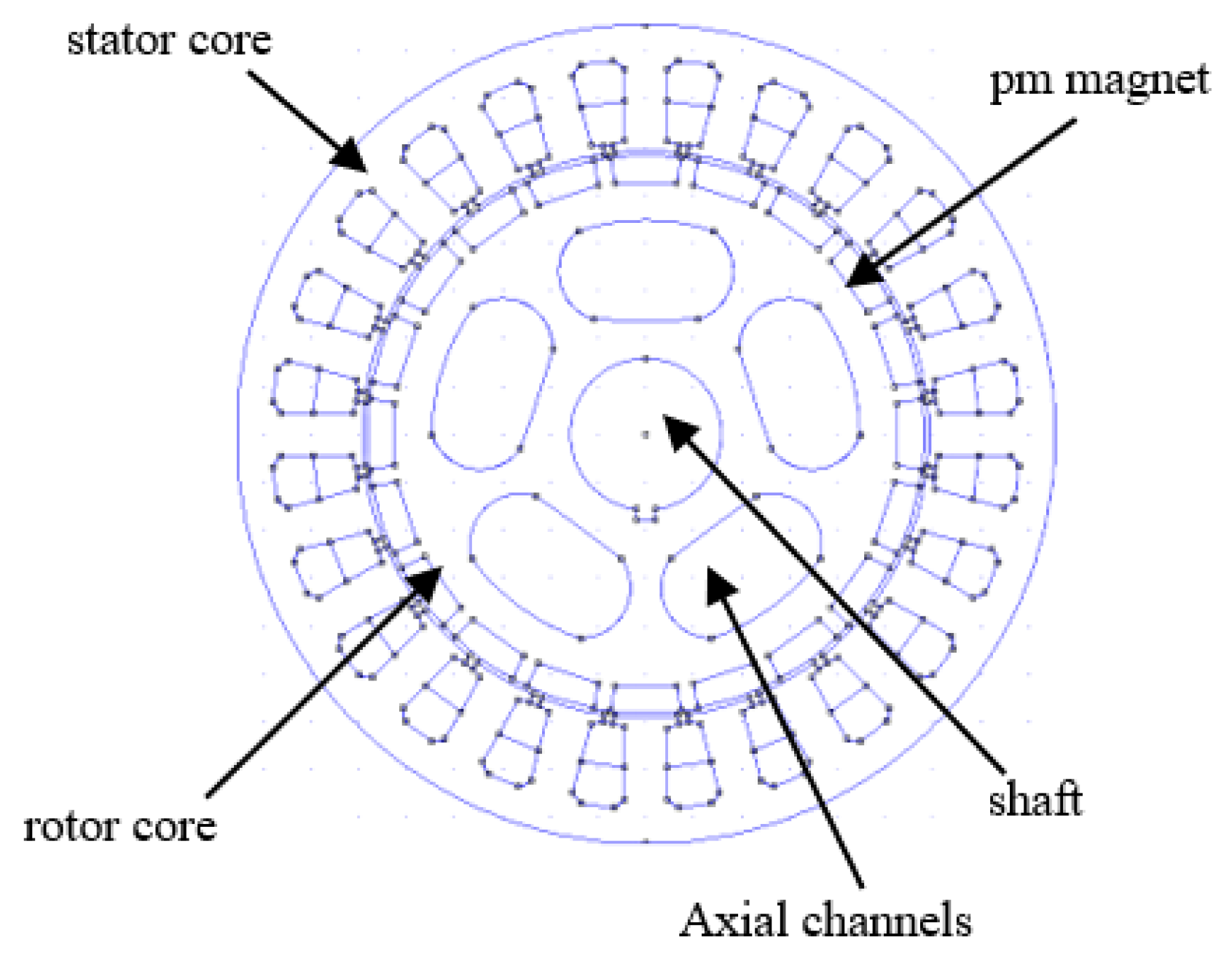
2.2. The Proposed Structure of PMG Studied

The authors chose three PMG configurations with FSNs featuring 20 poles and 24 slots to examine the impact of integrating TSS and pole arc optimization (PAO) at the magnet edges. One of the advantages of an FSN PMG in general is that, in its initial condition, it already has a relatively low CT compared to machines with an integral slot number (ISN). Specifically for the 20-slot and 20-pole construction, the distribution of magnetic flux is more regular and forms balanced groups in the stator core. This paper shows the magnetic flux distribution in the stator core. The PMGs analyzed in this study possess the structure illustrated in Figure 1. In permanent magnet motors (PMMs), the stator core has the same number of slots, height, width, number of teeth on the stator, and slot opening width as the original machine. This is shown in Figure 1. The fabrication of the magnet rotor is the only aspect in which the PMG diverges.
Figure 1 illustrates a cross-section of the structure of the permanent magnet generator (PMG) utilized in this study. The generator comprises a fixed stator core, which functions as the housing for the coil windings, and a revolving rotor core that contains permanent magnets to produce magnetic flux. The shaft is positioned centrally and functions as the axis of rotation for the rotor. The rotor features axial channels that diminish mass and enhance magnetic flux circulation, particularly in transverse flux generator configurations. This configuration influences the distribution of the magnetic field and the overall features of cogging torque. As seen in Figure 2 below, this initial model can be broken down into its component parts.
Figure 2 illustrates the initial configuration of the relationship between the permanent magnets (Pm NdFeB) and the stator component of a permanent magnet generator (PMG). It shows how stator teeth width and height affect the magnetic flux in coils. The airgap length between the rotor and stator affects flux transfer efficiency. Shoe height denotes the terminal segment of the stator teeth, characterized by a distinct geometry intended to channel the magnetic flux towards the surface of the permanent magnet. NdFeB (neodymium iron boron) magnets function as the primary source of magnetic flux in this system. It is crucial to consider this structure in the analysis and design of flux distributions to mitigate cogging torque. Additionally, a comparison of the magnetic structures among the three examined PMGs is outlined as follows (Table 1).
The stator and air gap dimensions of all three structures are identical, which is why the electromagnetic performance differences are predominantly influenced by the magnets’ geometry. The magnet profile of the initial structure is nearly planar and has the largest cross-sectional area. This profile has the potential to generate a higher magnetic flux, but it also tends to display increased cogging torque. In contrast, the OSS and TSS configurations have a decreased magnet edge height, resulting in a more curved or tapered shape that aids in the smoothing of the flux distribution and the reduction in cogging torque. However, this is achieved at the expense of a smaller magnet area. The reluctance and overall efficiency of magnetic induction are significantly influenced by the size of the stator teeth and the length of the air gap, which are crucial for directing the magnetic flow. The geometry of the three designs is seen in Figure 3 below.
Figure 3 illustrates the configuration of the stator teeth with three distinct designs of permanent magnets (NdFeB)—initial, OSS with PAO, and TSS with PAO—while maintaining uniformity in the width of the stator teeth and the height of the shoe. The preliminary design has a virtually flat magnet configuration with an expanded cross-sectional area, potentially enhancing flux while also resulting in elevated cogging torque. The OSS and PAO arrangement implements a more arcuate magnet profile to enhance flux distribution and diminish cogging torque. Simultaneously, the TSS and PAO design uses a two-step slotting configuration, enhancing the flux path and significantly reducing torque ripple.
The authors used FEMM 4.2 to examine the permanent magnet generator with a normal magnetic arrangement and tried to guess what the value of the current transformer would be. The peak CT of the PMG is around 0.0028437 Nm, as ascertained. Figure 3 shows how the one-step slotting (OSS) method and pole arc optimization at the magnet’s edge can be used to improve magnet structures. The magnetic force is approximately diminished to 0.0010658 Nm due to the reduction in magnetic material at its extremities. The intensity near the terminals of the magnet diminishes. As a result, the tangential magnetic force loses its ability to interact with the stator teeth, thereby drawing both the magnetic force and ferromagnetic material into the stator core. Nonetheless, the CT reduction of the PMG with a combination of OSS and PAO remains elevated for renewable energy applications.
To enhance the PMG’s magnet structure, two phases of slotting (TSS) and the PAO technique are incorporated at the magnet edge. Utilizing both TSS and PAO on the magnet increases the frequency of interaction between the magnet edge and the stator teeth. As a result, the cogging frequency escalates, but the peak value of the CT diminishes. The combination of the TSS and PAO procedures generates additional coordinate points near the magnet’s edge. The coordinate points at the magnet’s edge diminish the intensity of the tangential magnetic force at that location. The flux density at the magnet edge decreases, but the tangential magnetic flux density tends to circulate around the rotor teeth to maintain the magnetic flux distribution. Utilizing FEMM, the authors determined that the peak PMG of the CT, employing TSS and PAO methods, is diminished to around 0.0000179 Nm.

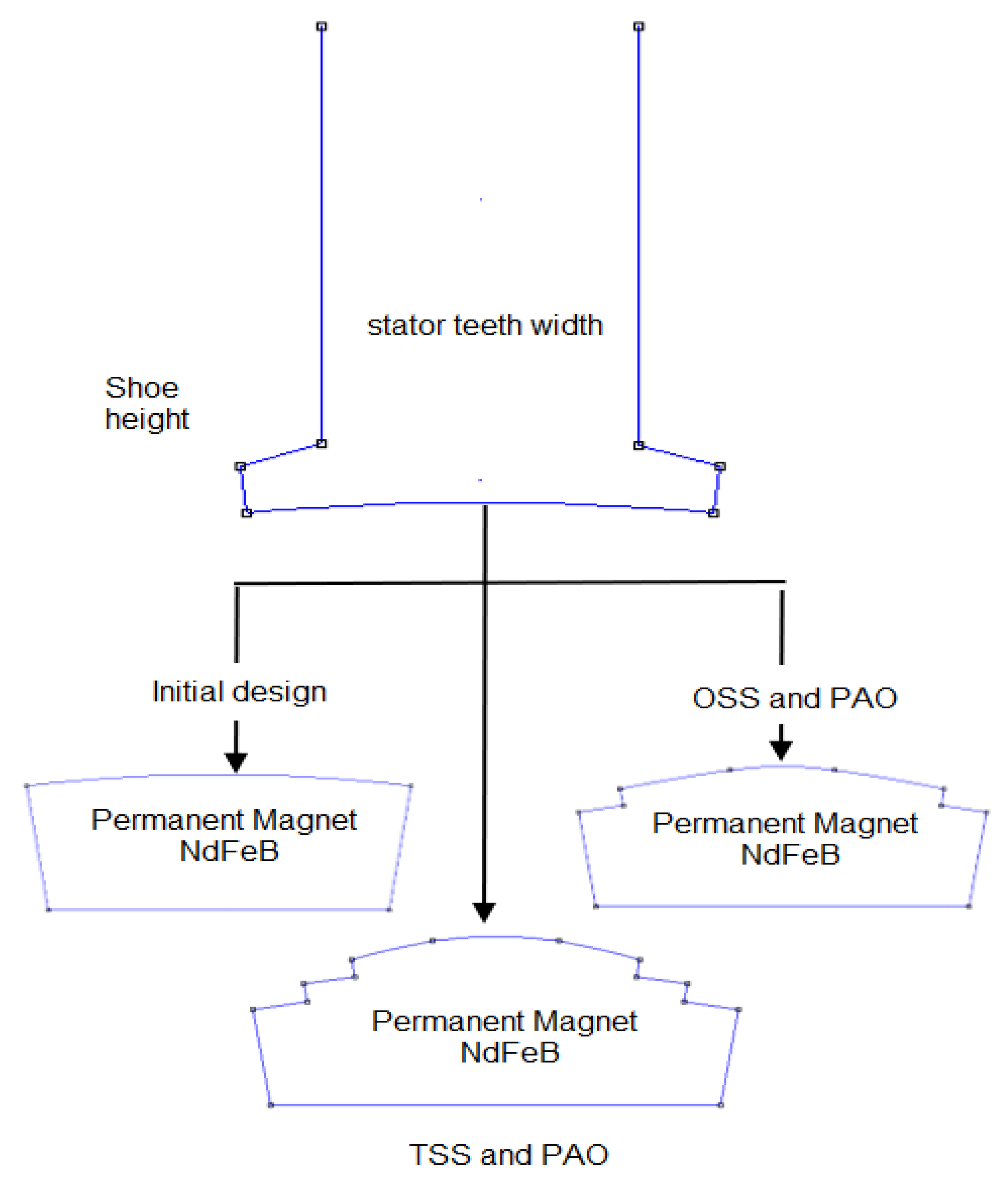
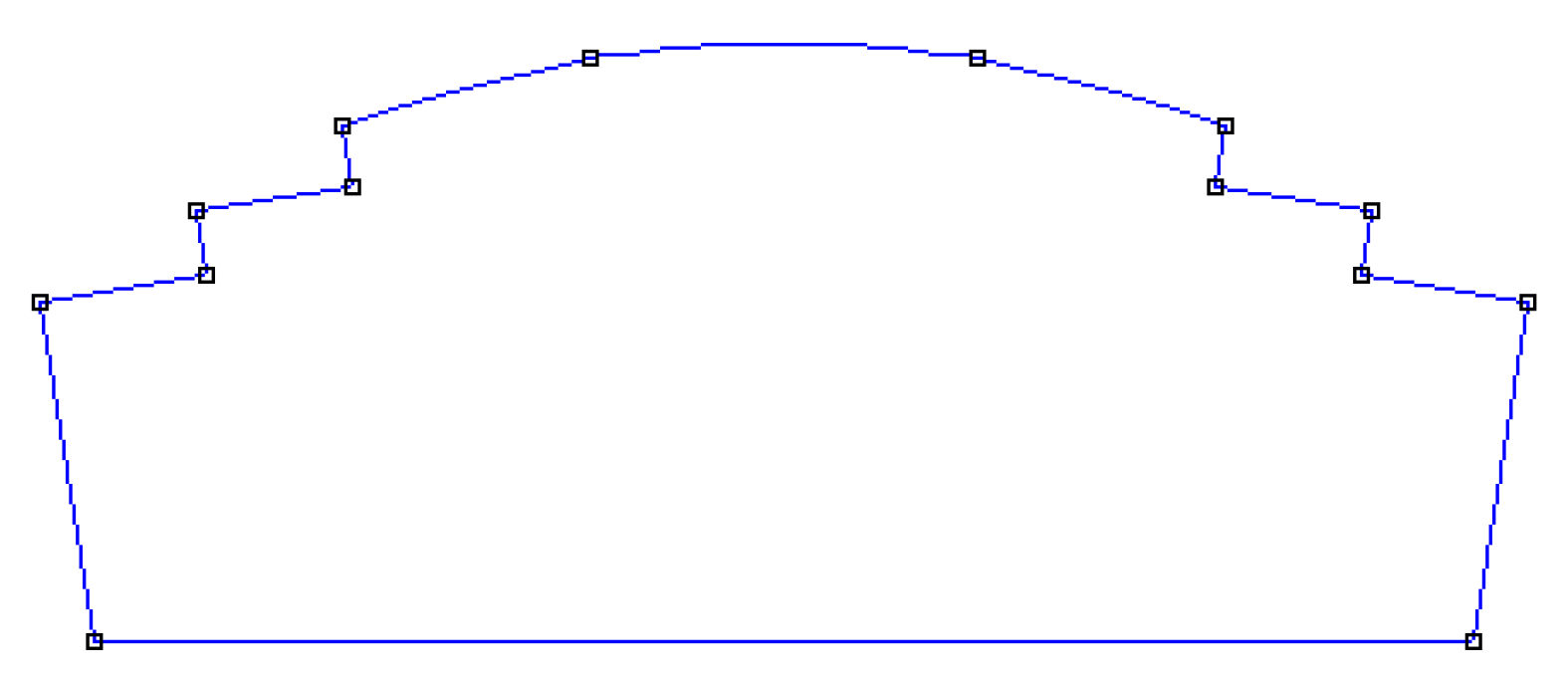
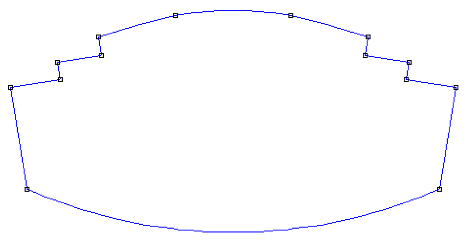
2.3. The Impact of Slotting on the Magnet Edge on the Reduction in CT

The magnet rotor of the PMG initially does not possess slots at the magnet’s edge and surface (see Figure 2). In Figure 2, the magnet’s height is uniform across its entirety. The distance between the magnet’s edge and slot opening is equivalent to that between its center and the stator core. Therefore, Figure 3 presents the utilization of the slotted magnet edge to lower the CT. According to our research, the PMG with both TSS and PAO at the magnet edge displays the biggest drop in CT, at about 0.0000179 Nm, compared to the other PMGs we examined. The PMG with OSS and PAO attains a CT reduction of 0.0010658 Nm, whereas that of the original structure persists at 0.0028437 Nm. The optimal strategy for CT reduction is a PMG combined with TSS and PAO.
As both the TSS technique and the POA technique were applied to the magnet’s edge in the PMG, the magnet’s height is ultimately diminished compared to its core. As a result, compared to the original configuration, the gap between the edges of the PMG’s magnets, which lack slotting, expands (Figure 4). Figure 4 illustrates the configuration of the permanent magnet utilizing the TSS approach, whereas Figure 5 depicts the configuration of the permanent magnet proposed in this study.
Each side of the magnet features slots with a dual-step design. This study analyzed and contrasted PMG structures with 24 slots and a 20-pole FSN. Conversely, the initial magnet model (Figure 2) used a commonly utilized magnet configuration devoid of slots. The decrease in cogging torque is markedly substantial when employing a magnet configuration like the two-level slot system depicted in Figure 4, rendering it appropriate for permanent magnet machines. The integration of this effect with the shaping at the magnet’s termini enhances its efficacy significantly. Trimming both ends of the magnet to a specific degree will yield an optimal distribution of magnetic flux entering the air gap. The truncation of both ends of the magnets increases the distance between them and the stator grooves. This technique results in an expansion of the air gap, hence reducing the reluctance of the air gap within the machine.
A significant amount of magnet material is wasted due to the cutting or trimming process involved in the two-step slotting mechanism at the magnet’s end, as illustrated in Figure 4. Consequently, the generator’s capacity to produce electrical power declines. Consequently, a method is required to restore the diminished power in the generator. The retrieval of potential electrical power lost owing to cogging remains infrequently addressed in academic research. The authors assert that it is feasible to regain the power diminished using cogging torque reduction. The authors utilized an optimization technique to mitigate the low power potential by augmenting the magnet volume through the design of a convex magnet structure. Figure 5 illustrates the construction of the magnet in a curved configuration directed towards the engine shaft, while maintaining the cuts at both extremities.
Along with that, FEMM checks the magnet arrangement using a convex system and compares it to the earlier machine design’s lower cogging torque. This research presents a comprehensive analysis of the reduction in cogging torque across all examined engine architectures. As shown in this work, the authors investigated the relationship between the cogging torque reduction method and the movement of the engine shaft while it was running. The FEMM analysis shows that the flat magnet system (Figure 4) can lower cogging torque by 99.03% under rated load conditions, while the convex magnet system can lower it by 99.02%. There is not much difference between the plate magnet in Figure 4 and the magnet with a convex system when it comes to reducing cogging torque. It can be said that increasing the magnet’s volume in a convex system does not cause cogging torque if the magnet’s surface is broken or trimmed. The effect of magnetic construction on shaft displacement alteration was also investigated. Using FEMM, the researchers found that using strategies to reduce cogging torque can cause the generator shaft to move 60% less than it did in the original design.

3. Results and Discussion

3.1. FEMM Simulation Setup

The CT of PMGs was examined using FEMM 4.2 based on the finite element analysis method [22,51,52]. FEMM 4.2 is a comprehensive software package extensively utilized for analyzing electrical structures [53]. The finite element method (FEMM) has been widely used in both academic and industrial settings worldwide. We conduct a performance analysis of the investigated PMGs using FEMM. In this work, we calculate and report the computed CT peak comparison results for PMGs investigated using a 24-slot/20-pole configuration. The process of analyzing permanent magnet generators (PMGs) using finite element methods includes the following steps:
  • Creating a direct model in the FEMM system or importing the PMG setup from AutoCAD version 2021. Rather than incorporating an AutoCAD image of the structure under examination, we directly render the PMG structures within the FEMM system.
  • Establishing parameters for evaluation. The FEMM interface enables the evaluation of the parameters of the analyzed PMGs.
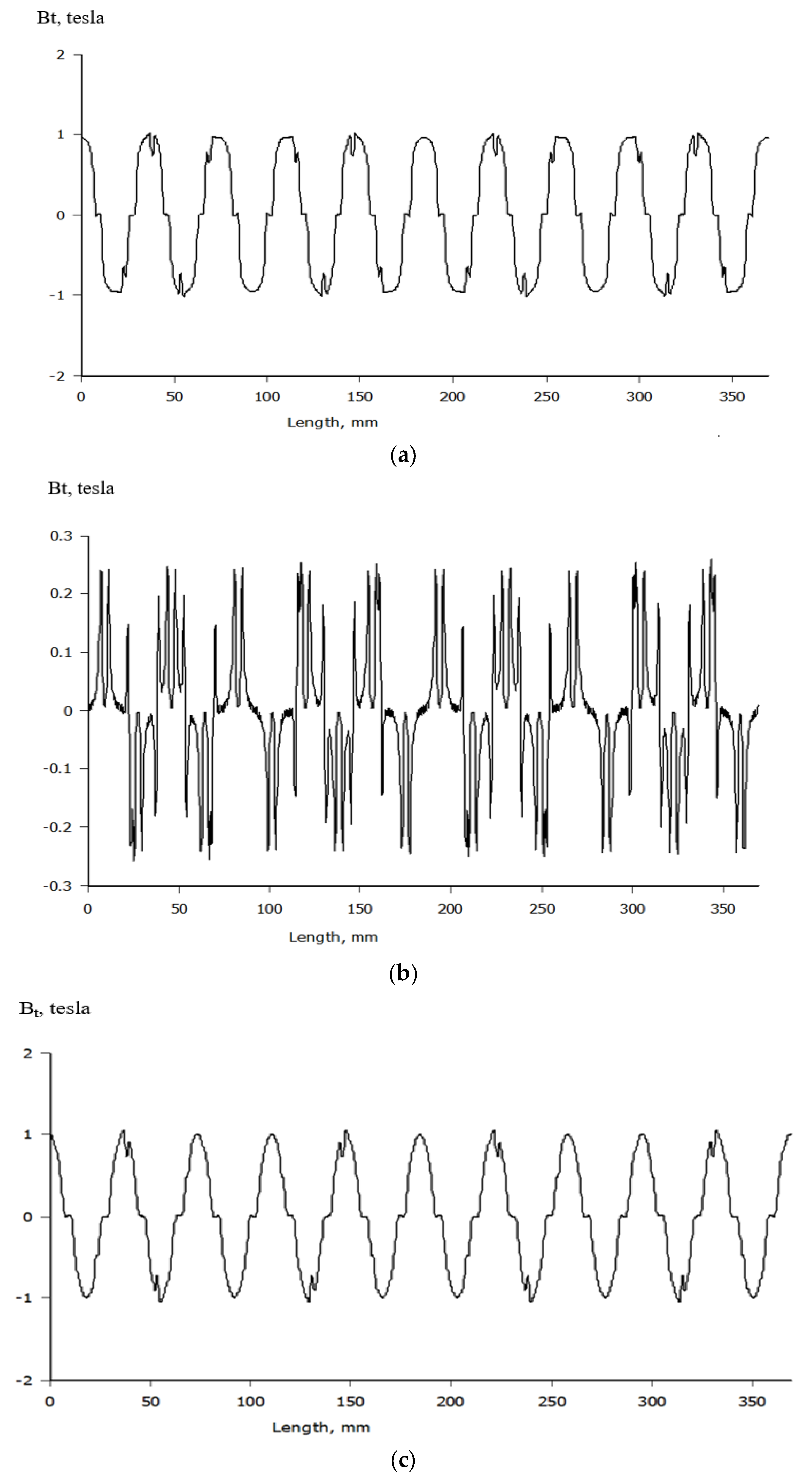
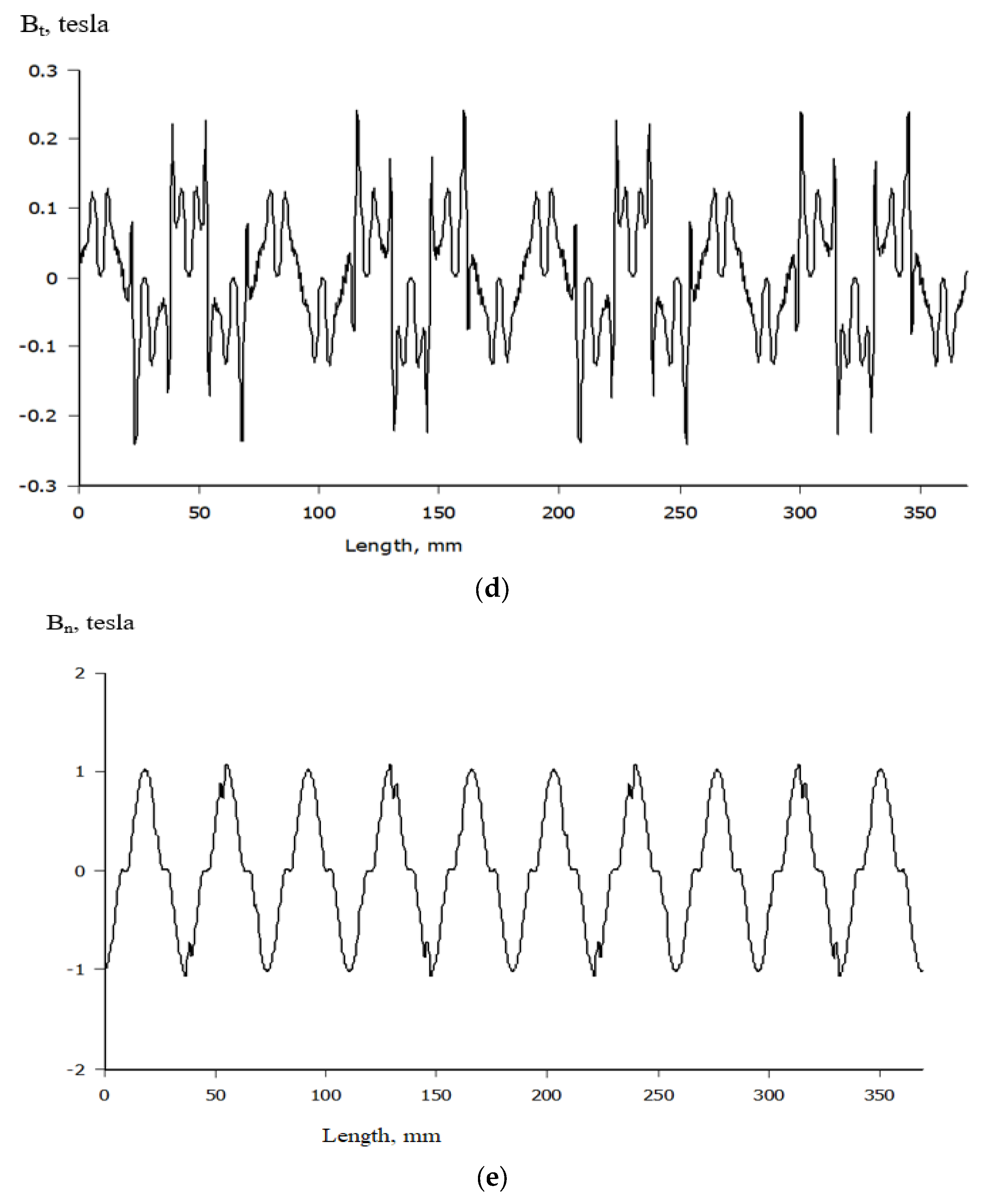
  • Calculating and determining the magnetic flux density. At this stage, we derive both the tangential and normal magnetic flux densities from the analyzed permanent magnet generators. We utilize five artificial lines at the air gap of all machines analyzed to guarantee precise calculations.
  • Recording the performance of the PMGs by determining the maximum CT value for the evaluated PMGs. The CT of PMGs is recorded for every mechanical degree of the magnet rotor’s rotation. Each rotational increment produces a mechanical revolution of 10 degrees.
  • Rotors reaching a definitive position. Given that the examined PMGs have a pole count of 20, the computation of PMG CT requires 360 mechanical rotations.
  • Providing conclusions.
If the decrease in PMG CT is not achieved, the size of the magnet slotting must be modified and thereafter reverted to the values established in step 2. If all prerequisites are met, the flow may cease. The subsequent sections of this study analyze various critical aspects of the impact of the magnet structure on the CT peak of PMG.

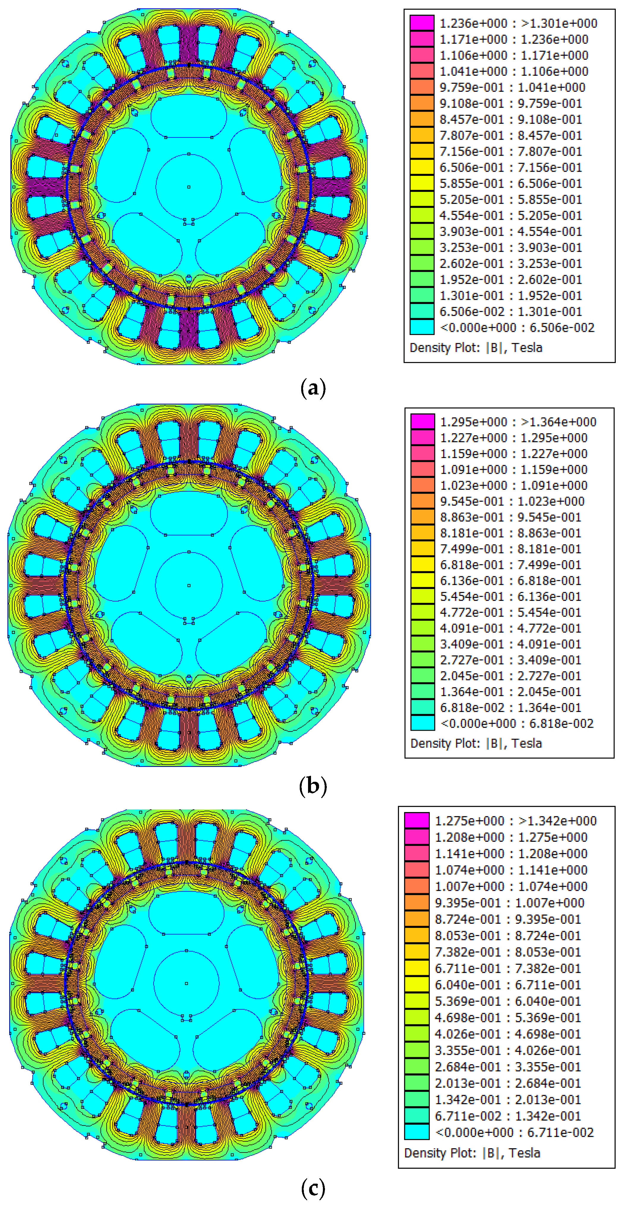
3.2. The Magnet Flux Density Value in the Core of Every PMG Under Investigation

The normal magnetic flux density in the PMG core is an important component to consider when maintaining the machine’s efficiency and power production. The standard magnetic flux density at the machine’s core must not exceed 1.5 Tesla, depending upon the material capacity load utilized for the PMG structure [48]. This structure uses M-19 steel for the rotor and stator cores of the machine. Research indicates that the magnetic flux density for M-19 must remain below 1.5 Tesla to avoid saturation of the PMG core and a subsequent reduction in the machine’s efficiency. The proposed PMGs in this study use both TSS and PAO methods and have a 1.483 Tesla magnetic flux density. This value indicates that the machine core will not overheat under loading. The magnetic flux density of the investigated PMGs is presented.
Figure 6a presents the distribution of magnetic flux density in the initial PMG configuration. A significant flux concentration is noted in the stator teeth, with maximum values surpassing 1.3 T, signifying localized magnetic saturation. The flux lines are concentrated and irregularly dispersed, potentially resulting in increased cogging torque and diminished magnetic coupling efficiency. The application of the TSS approach at the machine’s magnet edge reduces the tangential magnetic flux density at that location. The tangential magnetic flux density reduces because of the single steps of slotting (OSS) and TSS in making the magnet, which can be seen in Figure 6b,c. Nonetheless, the TSS technique may diminish the tangential magnetic flux density to a greater extent than the OSS strategy. This change may be attributable to the increase in the point coordinates of the magnet using the TSS approach. The amplitude of CT diminishes at greater levels. Both TSS and OSS display virtually identical peaks in tangential magnetic flux density. Conversely, in comparison to OSS, TSS generally exhibits a reduced magnetic flux density profile. The normal magnetic flux density of TSS frequently exhibits a sine wave pattern, as illustrated in Figure 7e. The suggested PMG has the lowest amount of total magnetic flux entering the air gap compared to the original structure and OSS, which is used as the PMG baseline model.

3.3. Value of the Tangential and Normal Magnetic Flux in the PMG’s Airgap

The tangential and normal PMG air gap values are examined and compared in this study. They are shown in Figure 7a–e, respectively.
Figure 7 shows how normal and tangential flux densities are spread out in the air gap of a permanent magnet generator (PMG) for different magnet edge designs. In Figure 7a, the normal flux density of the first design has a wavy shape that is quite distorted, indicating a fairly concentrated flux distribution. Figure 7b shows the tangential flux density of the same initial design, which has high peaks and quick changes, indicating a strong potential for cogging torque. As shown in Figure 7c, using the one-step slotting (OSS) technique slightly smooths out the normal flux density, but Figure 7d shows that OSS significantly reduces the height and sharpness of the tangential flux peaks, which means that the flux is more evenly spread and there is less torque ripple. Ultimately, Figure 8 shows the tangential flux density obtained by using two-step slotting (TSS) and pole arc optimization (PAO), which results in less distortion and lower peak values. This signifies improved magnetic efficacy and efficient cogging torque mitigation.

3.4. The Cogging Torque Value for the PMGs Under Study

A critical element in the application of PMGs in renewable energy systems is the CT peak value. The CT peak of a PMG utilized in a renewable energy system must be minimized as much as possible to optimize PMG performance. The study analyzed and presented the CT result values of the PMGs under examination. The application of the TSS and PAO technique at the PMG’s magnet edge indicates a significant reduction. Equation (7) is employed to determine the CT values of the PMGs under examination. Figure 8 illustrates the comparison of CT values among the examined PMGs.
The peak CT value for the original structure is around 0.0028437 Tesla, as illustrated in Figure 8. This reduction is due to a robust magnetic flux interaction between the magnet edge and the slot opening. Utilizing the OSS at the magnet edge results in the PMG’s CT decreasing to 0.0010769. Nonetheless, in an application utilizing renewable energy, the reduction in CT in PMG through the OSS technique is no longer significant. Utilizing the TSS and PAO methodology at the magnet edge can markedly decrease the CT to 0.0000179 Tesla. The CT reduction for the PMG with the 24-slot, 20-pole configuration is approximately 99.3%.
The highest peak cogging torque value of the proposed PMG is 0.0000179 Nm, while the highest peak cogging torque value of the initial structure is 0.0028437 Nm. The percentage decrease in the cogging torque of the proposed PMG against the initial structure is as follows:
T c   % = 100 % (   0.0000179 0.0028437 ) 100 % = 100 % 0.0063 % = 99.99 %
This means that decreasing the magnet’s volume alone is not as effective at lowering the cogging force, especially if the distance between the magnets stays the same throughout the structure, especially between the magnet tips and the stator slot. According to research, cogging torque is greatly reduced by making the magnet smaller and the distance between its ends and the stator teeth longer than the magnet’s center. The height at both extremities of the magnet is less than that at its center.
Moreover, it may be asserted that if the reduction in magnet volume coincides with an increase in the distance between the magnet’s ends, which is significantly greater than the magnet’s center, the attractive force between the magnet’s ends and the stator slot may diminish substantially. The distribution of flux or magnetic lines of force at the magnet’s ends that extend to the stator slot diminishes considerably. As the intensity of the magnetic lines of force directed toward the groove diminishes, the magnetic force securing the ferromagnet within the stator slot also decreases. The magnet’s substantial bulk disperses magnetic flux into the air gap. This influences the reluctance of the air it traverses and produces an air gap magnetic force. While the magnet rotor spins, the considerable flux interacts with the fluctuating resistance, generating a notable cogging force. The uniform height of the magnet construction contributes to the elevated cogging force. Because the magnet’s height is spread out evenly, the tangential and radial magnetic fluxes are equal or almost equal. This causes them to superposition, which makes it easier for the magnet to enter the air gap. When the magnetic lines of force traverse the air gap, they can connect the left and right sides of the ferromagnetic stator teeth.
For instance, if the opening slot on the stator core is excessively large, magnetic lines of force will accumulate in the slot, further distancing the stator core from the interior. A pulling force exists between the magnet’s ends and the stator core, which intensifies as additional magnetic lines of force penetrate the expansive stator slot. This intensifies the cogging torque. The integer composition of slots and magnetic poles in permanent magnet generators results in a substantial total flux entering the air gap. This is due to the fact that the total flux entering the air gap is a composite of the magnetic flux from each phase. Furthermore, magnetic materials with high remanence flux typically generate increased cogging torque relative to those with lower remanence flux.

4. Conclusions

This study examines the influence of various magnet configurations on CT reduction and proposes the integration of the PAO and TSS techniques at the edges of the PMG magnet. The author employed FEMM version 4.2 to ascertain the magnetic flux density values of three distinct magnet structures and subsequently compared the findings. The magnetic flux density of our proposed PMG core is intended to increase to 1.275 Tesla, surpassing the 1.236 Tesla value of the first construction. The rising magnetic flux density within the PMG core indicates that the utilization of M-19 is acceptable, as it remains below 1.5 Tesla, the saturation threshold for M-19. Moreover, the normal and tangential magnetic flux densities decreased to 0.19 Tesla. The tangential magnetic flux density is around 0.2 Tesla. The magnetic flux density peaks of all three PMGs under examination were compared. Approximately 1 Tesla is the initial structural peak of standard flux density. The TSS and OSS maximums remain at 1 Tesla.
The normal magnetic flux density waveform for the proposed PMG, on the other hand, has a thinner shape and looks like a sine curve. The most significant decrease in CT, relative to the original structure, occurs when the suggested PMG is diminished through TSS. The proposed reduction in the PMG’s CT from the initial configuration was around 96.30%. Employing a concave magnet configuration to maintain the magnet’s cross-section may also assist the suggested PMG in regaining its potential power capacity. With this magnet configuration, the magnet could attain a volume equivalent to that of the baseline model. The power potential of the proposed magnet retains the same construction, although the CT is markedly diminished. The use of TSS and a gradually inclined surface end (GISE) in the magnet structure suggests that CT can be cut down by a large amount. The suggested reduction in PMG may improve its performance. Renewable energy systems ought to employ the PMG configuration utilizing TSS and PAO technologies at the magnet edge.

Author Contributions

Conceptualization, S.A. and T.N.; methodology, S.K.; software, T.N.; validation, S.A., S.K. and T.N.; formal analysis, S.A.; investigation, S.K.; resources, T.N.; data curation, T.N.; writing—original draft preparation, S.A. and T.N.; writing—review and editing, S.K.; visualization, T.N.; supervision, S.A.; project administration, S.A. and S.K.; funding acquisition, S.K. All authors have read and agreed to the published version of the manuscript.

Funding

This research was funded by UNITEN, grant number 0130/PJ/1/A0/10/2023.

Data Availability Statement

The data presented in this study are available on request from the corresponding author. The data are unavailable due to privacy or ethical restrictions.

Acknowledgments

We express our appreciation to the collaborative research project ITPLN–UNITEN for its financial support.

Conflicts of Interest

The authors declare no conflicts of interest.

References

  1. Padmanathan, K.; Kamalakannan, N.; Sanjeevikumar, P.; Blaabjerg, F.; Holm-Nielsen, J.B.; Uma, G.; Arul, R.; Rajesh, R.; Srinivasan, A.; Baskaran, J. Conceptual Framework of Antecedents to Trends on Permanent Magnet Synchronous Generators for Wind Energy Conversion Systems. Energies 2019, 12, 2616. [Google Scholar] [CrossRef]
  2. Hwang, C.C.; Tang, P.H. Performance and applications of a small permanent magnet generator. In Proceedings of the 2005 IEEE International Magnetics Conference (INTERMAG), Nagoya, Japan, 4–8 April 2005; p. 335. [Google Scholar]
  3. Mostaman, N.; Sulaiman, E.; Jenal, M. Overview of Axial Flux Permanent Magnet Generator for Small-Scale Industry. IOP Conf. Ser. Earth Environ. Sci. 2023, 1261, 12004. [Google Scholar] [CrossRef]
  4. Rahman, A.; Dutta, R.; Chu, G.; Xiao, D.; Thippiripati, V.K.; Rahman, M.F. Open-Winding Permanent Magnet Synchronous Generator for Renewable Energy—A Review. Energies 2023, 16, 5268. [Google Scholar] [CrossRef]
  5. Chung, D.-W.; Yongmin, Y. Cogging Torque Reduction in Permanent-Magnet Brushless Generators for Small Wind Turbines. J. Magn. 2015, 20, 176–185. [Google Scholar] [CrossRef]
  6. Yazdanpanah, R.; Afroozeh, A.; Eslami, M. Analytical design of a radial-flux PM generator for direct-drive wind turbine renewable energy application. Energy Rep. 2022, 8, 3011–3017. [Google Scholar] [CrossRef]
  7. Herlina; Rahardjo, A.; Sudiarto, B.; Setiabudy, R. The Implement of Permanent Magnet Material Variations on the Reduction of Cogging Torque in PMSG. IOP Conf. Ser. Mater. Sci. Eng. 2019, 620, 12101. [Google Scholar] [CrossRef]
  8. Ladghem-Chikouche, B.; Boughrara, K.; Ibtiouen, R. Cogging Torque Minimization of Surface-Mounted Permanent Magnet Synchronous Machines Using Hybrid Magnet Shapes. Prog. Electromagn. Res. B 2015, 62, 49–61. [Google Scholar] [CrossRef]
  9. Said, S.M.; Nur, T.; Herlina, H. The Application of Magnet Structures to Reduce the Cogging Torque Associated with Fractional Slot Number in Permanent Magnet Generators. Energies 2024, 17, 2505. [Google Scholar] [CrossRef]
  10. García-Gracia, M.; Jiménez Romero, Á.; Herrero Ciudad, J.; Martín Arroyo, S. Cogging Torque Reduction Based on a New Pre-Slot Technique for a Small Wind Generator. Energies 2018, 11, 3219. [Google Scholar] [CrossRef]
  11. Nasiri-Zarandi, R.; Ghaheri, A.; Abbaszadeh, K. Cogging Torque Reduction in U-Core TFPM Generator Using Different Halbach-Array Structures. In Proceedings of the 2018 International Symposium on Power Electronics, Electrical Drives, Automation and Motion (SPEEDAM), Amalfi, Italy, 20–22 June 2018; pp. 1153–1158. [Google Scholar]
  12. Potgieter, J.H.J.; Kamper, M.J. Cogging torque sensitivity in design optimisation of low cost non-overlap winding PM wind generator. In Proceedings of the the XIX International Conference on Electrical Machines–CEM 2010, Rome, Italy, 6–8 September 2010; pp. 1–6. [Google Scholar]
  13. Herlina; Setiabudy, R.; Rahardjo, A. Influence of permanent magnet and width of stator slot to cogging torque reduction in PMSG using anti-notch and cutting edge method. In Proceedings of the 2017 15th International Conference on Quality in Research (QiR): International Symposium on Electrical and Computer Engineering, Nusa Dua, Bali, 24–27 July 2017; pp. 408–413. [Google Scholar]
  14. Zhang, Y.; Wang, F. Choice of Pole-Slot Number Combination for PM Generator Direct-Driven by Wind Turbine. In Proceedings of the 2008 Joint International Conference on Power System Technology and IEEE Power India Conference, New Delhi, India, 12–15 October 2008; pp. 1–4. [Google Scholar]
  15. Shao, L.; Hua, W.; Soulard, J.; Zhu, Z.-Q.; Wu, Z.; Cheng, M. Electromagnetic Performance Comparison Between 12-Phase Switched Flux and Surface-Mounted PM Machines for Direct-Drive Wind Power Generation. IEEE Trans. Ind. Appl. 2020, 56, 1408–1422. [Google Scholar] [CrossRef]
  16. Zhou, Y.; Li, H.; Meng, G.; Zhou, S.; Cao, Q. Analytical Calculation of Magnetic Field and Cogging Torque in Surface-Mounted Permanent-Magnet Machines Accounting for Any Eccentric Rotor Shape. IEEE Trans. Ind. Electron. 2015, 62, 3438–3447. [Google Scholar] [CrossRef]
  17. Huang, C.; Jia, R.; Chen, B.; Zhang, M.; Chen, H.; Wang, Y.; Mao, J. Research on Cogging Torque Reduction Based on Multi-Parameter Optimization of Auxiliary Slots and Pole-Arc Coefficient. J. Electr. Eng. Technol. 2025, 20, 1439–1449. [Google Scholar] [CrossRef]
  18. Nur, T.; Muljadi, E.; Herlina; Kasbi, S.; Ling, J.M. The Effect of the Number of Concentrate Slots and Pole Arc Optimization on the Cogging Torque Reduction in Fractional Slot Number Type of PMMs. In Proceedings of the 2021 24th International Conference on Electrical Machines and Systems (ICEMS), Gyeongju, Republic of Korea, 31 October–3 November 2021; pp. 17–22. [Google Scholar]
  19. Wahab, H.; Nur, T.; Kartawidjaja, M.; Wijayanti, L.; Indriati, K.; Tobing, S. Declining Cogging Torque Technique of an Integral Slot Number for Permanent Magnet Machines. J. Rekayasa Elektr. 2023, 19, 135–142. [Google Scholar] [CrossRef]
  20. Petkovska, L.; Lefley, P.; Cvetkovski, G. Design techniques for cogging torque reduction in a fractional-slot PMBLDC motor. COMPEL Int. J. Comput. Math. Electr. Electron. Eng. 2020, ahead of print. [Google Scholar] [CrossRef]
  21. Zhu, Z.Q.; Wu, D.; Ge, X. Investigation of Voltage Distortion in Fractional Slot Interior Permanent Magnet Machines Having Different Slot and Pole Number Combinations. IEEE Trans. Energy Convers. 2016, 31, 1192–1201. [Google Scholar] [CrossRef]
  22. Nur, T.; Suherman, Y.; Wahab, H. The Effect of Magnet Structure on the Cogging Torque Reduction in a Permanent Magnet Generator. J. Southwest Jiaotong Univ. 2021, 56, 313–323. [Google Scholar] [CrossRef]
  23. Nur, T.; Mawar, S. Improvement of Cogging Torque Reduction by Combining the Magnet Edge Shaping and Dummy Slot in Stator Core of Fractional Slot Number in Permanent Magnet Machine. IOP Conf. Ser. Mater. Sci. Eng. 2020, 807, 12023. [Google Scholar] [CrossRef]
  24. Hamadou, G.; Masmoudi, A. On the cogging torque reduction capability of fractional-slot PM machines. J. Electr. Eng. 2011, 11, 8. [Google Scholar]
  25. Chen, X.; Wang, J. Magnetomotive force harmonic reduction techniques for fractional-slot non-overlapping winding configurations in permanent-magnet synchronous machines. Chinese J. Electr. Eng. 2017, 3, 102–113. [Google Scholar] [CrossRef]
  26. Nakano, M.; Morita, Y.; Matsunaga, T. Reduction of Cogging Torque Due to Production Tolerances of Rotor by Using Dummy Slots Placed Partially in Axial Direction. IEEE Trans. Ind. Appl. 2015, 51, 4372–4382. [Google Scholar] [CrossRef]
  27. Lan, H.; Chen, Q.; Zou, J.; Xu, Y.; Wang, M.; Liu, M. Influence of dummy slots on noise and vibration performance in permanent magnet synchronous machines. In Proceedings of the 2017 IEEE Transportation Electrification Conference and Expo, Asia-Pacific (ITEC Asia-Pacific), Harbin, China, 7–10 August 2017; pp. 1–6. [Google Scholar]
  28. Joe, L.; Nur, T. Study the Effect of Dummy Slot in Stator and Rotor on the Cogging Torque Reduction in Permanent Magnet Machine. IOP Conf. Ser. Mater. Sci. Eng. 2020, 807, 12025. [Google Scholar] [CrossRef]
  29. Sato, D.; Maejima, R.; Kitagawa, W.; Takeshita, T. Cogging Torque Reduction by Using Double Skew of Permanent Magnets in Axial Gap Motor. In Proceedings of the 2022 International Conference on Electrical Machines (ICEM), Valencia, Spain, 5–8 September 2022; pp. 212–218. [Google Scholar]
  30. Luu, P.T.; Lee, J.-Y.; Hwang, W.; Woo, B.-C. Cogging Torque Reduction Technique by Considering Step-Skew Rotor in Permanent Magnet Synchronous Motor. In Proceedings of the 2018 21st International Conference on Electrical Machines and Systems (ICEMS), Jeju, Republic of Korea, 7–10 October 2018; pp. 219–223. [Google Scholar]
  31. Mizuno, A.; Kitagawa, W.; Takaharu, T. Cogging Torque Reduction Using Magnet Phase Inverted Shape in Dual Axial Gap Motor. In Proceedings of the 2024 IEEE Industrial Electronics and Applications Conference (IEACon), Kuala Lumpur, Malaysia, 4–5 November 2024; pp. 112–117. [Google Scholar]
  32. Jia, L.; Lin, M.; Le, W.; Li, N.; Kong, Y. Dual-Skew Magnet for Cogging Torque Minimization of Axial Flux PMSM With Segmented Stator. IEEE Trans. Magn. 2020, 56, 1–6. [Google Scholar] [CrossRef]
  33. Gulec, M.; Aydin, M. Magnet asymmetry in reduction of cogging torque for integer slot axial flux permanent magnet motors. Electr. Power Appl. IET 2014, 8, 189–198. [Google Scholar] [CrossRef]
  34. Lounthavong, V.; Sriwannarat, W.; Siritaratiwat, A.; Khunkitti, P. Optimal Stator Design of Doubly Salient Permanent Magnet Generator for Enhancing the Electromagnetic Performance. Energies 2019, 12, 3201. [Google Scholar] [CrossRef]
  35. Nur, T. Herlina Investigation of the Implement the Shoe Height and Slot Opening Width on Decreasing the Peak of Cogging Torque in PMSG. In Proceedings of the 2019 International Conference on Electrical Engineering and Computer Science (ICECOS), Batam Island, Indonesia, 2–3 October 2019; pp. 411–415. [Google Scholar]
  36. Kwang, T.C.; Mohd Jamil, M.L.; Jidin, A. Improved magnetic behavior of hemicycle PM motor via stator modification. Int. J. Electr. Comput. Eng. 2020, 10, 3323. [Google Scholar] [CrossRef]
  37. Sjölund, J.; Eriksson, S. Effect of Pole Shoe Design on Inclination Angle of Different Magnetic Fields in Permanent Magnet Machines. Energies 2021, 14, 2437. [Google Scholar] [CrossRef]
  38. Anuja, T.A.; Doss, M.A. Reduction of Cogging Torque in Surface Mounted Permanent Magnet Brushless DC Motor by Adapting Rotor Magnetic Displacement. Energies 2021, 14, 2861. [Google Scholar] [CrossRef]
  39. Panchal, T.; Patel, A.; Patel, R. Reduction of cogging torque of radial flux permanent magnet brushless DC motor by magnet shifting technique. Electr. Eng. Electromec. 2022, 15–20. [Google Scholar] [CrossRef]
  40. Yea, M.; Han, K.J. Modified Slot Opening for Reducing Shaft-to-Frame Voltage of AC Motors. Energies 2020, 13, 760. [Google Scholar] [CrossRef]
  41. Liu, T.; Huang, S.; Gao, J.; Lu, K. Cogging Torque Reduction by Slot-Opening Shift for Permanent Magnet Machines. IEEE Trans. Magn. 2013, 49, 4028–4031. [Google Scholar] [CrossRef]
  42. Liu, C.; Zhu, J.; Wang, Y.; Lei, G.; Guo, Y. Cogging Torque Minimization of SMC PM Transverse Flux Machines Using Shifted and Unequal-Width Stator Teeth. IEEE Trans. Appl. Supercond. 2016, 26, 1–4. [Google Scholar] [CrossRef]
  43. Bianchi, N.; Bolognani, S.; Cappello, A.D.F. Reduction of cogging force in PM linear motors by pole-shifting. Electr. Power Appl. IEE Proc. 2005, 152, 703–709. [Google Scholar] [CrossRef]
  44. Goryca, Z.; Pakosz, A. Influence of selected reduction methods on the cogging torque of multipolar machines with permanent magnets. In Proceedings of the 2019 15th Selected Issues of Electrical Engineering and Electronics (WZEE), Zakopane, Poland, 8–10 December 2019; pp. 1–6. [Google Scholar]
  45. Xing, Z.; Wang, X.; Zhao, W. Cogging torque reduction based on segmented skewing magnetic poles with different combinations of pole-arc coefficients in surface-mounted permanent magnet synchronous motors. IET Electr. Power Appl. 2021, 15, 200–213. [Google Scholar] [CrossRef]
  46. Kudrjavtsev, O.; Kilk, A. Cogging torque reduction methods. In Proceedings of the 2014 Electric Power Quality and Supply Reliability Conference (PQ), Rakvere, Estonia, 11–13 June 2014; pp. 251–254. [Google Scholar]
  47. Cetin, E. Cogging torque reduction by utilizing the unequal rotor slot arc method for FSPM Machines. Ain Shams Eng. J. 2024, 15, 103008. [Google Scholar] [CrossRef]
  48. Gieras, J.; Wing, M. Permanent Magnet Motor Technology: Design and Applications; CRC Press: Boca Raton, FL, USA, 2013. [Google Scholar]
  49. Scuiller, F. Magnet Shape Optimization to Reduce Pulsating Torque for a Five-Phase Permanent-Magnet Low-Speed Machine. IEEE Trans. Magn. 2014, 50, 1–9. [Google Scholar] [CrossRef]
  50. Hanselman, D. Brushless Permanent Magnet Motor Design; The Writers’ Collective: Cranston, RI, USA, 2003. [Google Scholar]
  51. Nur, T.; Joe, L.E. Study of The Effect of Height and Length of Slotting in Magnet Edge on the Cogging Torque Reduction of Fractional Slot Number in Permanent Magnet Machine. IOP Conf. Ser. Mater. Sci. Eng. 2020, 807, 12026. [Google Scholar] [CrossRef]
  52. Srisiriwanna, T.; Konghirun, M. A study of cogging torque reduction methods in brushless dc motor. In Proceedings of the 2012 9th International Conference on Electrical Engineering/Electronics, Computer, Telecommunications and Information Technology, Phetchaburi, Thailand, 16–18 May 2012; pp. 1–4. [Google Scholar]
  53. David Meeker Finite Element Method Magnetics: MagneticsTutorial. Available online: https://www.femm.info/wiki/davidmeeker (accessed on 14 December 2013).
Figure 1. Cross-sectional area of PMGs studied.
Energies 18 02802 g001
Figure 2. Highlights of the magnet and stator structure (initial structure).
Energies 18 02802 g002
Figure 3. Stator teeth with different magnet structures.
Energies 18 02802 g003
Figure 4. Magnet structure with TSS.
Energies 18 02802 g004
Figure 5. Proposed magnet structure.
Energies 18 02802 g005
Figure 6. Magnetic flux density of PMMs studied. (a) Initial structure. (b) One step of slotting. (c) Proposed PMG structure (combining the TSS and PAO techniques).
Energies 18 02802 g006
Figure 7. Magnetic flux density at the air gap of the PMGs studied. (a) Normal flux density at the airgap of the initial design. (b) Tangential flux density at the airgap of the initial design. (c) Normal flux density at the airgap of the PMG with one-step slotting at the magnet edge. (d) Tangential flux density at the airgap of the PMG with one-step slotting at the magnet edge. (e) Normal flux density at the air gap of the proposed PMG combining the TSS and PAO techniques at the magnet edge.
Energies 18 02802 g007aEnergies 18 02802 g007b
Figure 8. Comparison of CT reduction among the PMGs studied.
Energies 18 02802 g008
Table 1. Comparison of magnet and stator dimensions for three structural designs.
ParameterInitial StructureOSS (One-Step Slotting)TSS (Two-Step Slotting)
Stator teeth height (mm)14.996914.996914.9969
Stator teeth width (mm)9.151319.151319.15131
Shoe height (mm)1.51.51.5
Air gap length (mm)1.01.01.0
Magnet edge height (mm)5.287583.837583.28758
Magnet center height (mm)5.659915.659915.65991
Magnet base length (mm)13.083613.083613.0836
Magnet cross-sectional area (m2)7.7235 × 10−56.9397 × 10−56.50519 × 10⁻⁵
Disclaimer/Publisher’s Note: The statements, opinions and data contained in all publications are solely those of the individual author(s) and contributor(s) and not of MDPI and/or the editor(s). MDPI and/or the editor(s) disclaim responsibility for any injury to people or property resulting from any ideas, methods, instructions or products referred to in the content.

