Abstract
Waste heat utilization in fuel cell vehicles represents a critical technology for enhancing overall energy utilization efficiency and environmental adaptability, which reduces auxiliary heating consumption, extends driving range, and minimizes thermal management parasitic losses, holding significance for promoting application of fuel cell commercial vehicles. This study investigates a 49-ton fuel cell heavy-duty truck equipped with waste heat recovery capability, conducting vehicle energy flow experiments under multiple ambient temperatures (including 7 °C, °C and °C extreme cold conditions), varying load conditions, and waste heat recovery mode switching, with focused analysis on the energy consumption and temperature response of the waste heat recover critical components, to evaluate the energy utilization of fuel cell waste heat. Experimental results demonstrate the substantial impact of waste heat recovery function on the proportion of the warm air positive temperature coefficient (PTC) energy consumption on total energy consumption, showing that deactivating waste heat recovery increased the PTC energy consumption obviously. Besides, activating the waste heat recovery function contributes to elevated the stack radiator outlet temperature under low-temperature operating conditions.
1. Introduction
The advancement of new energy vehicles represents a critical pathway for the global automotive industry to achieve its low-carbon objectives. Within the transportation sector, medium- and heavy-duty commercial vehicles are the primary contribution to carbon emissions, accounting for approximately 65% of the total [1,2]. With this, the electrification of heavy-duty, long-haul commercial vehicles is an urgent priority. As presented in [3] concerning the advancement of electric vehicles, fuel cell electric vehicles, owing to their advantages such as rapid refueling and extended driving range, are anticipated to emerge as a dominant technological solution for future medium- and heavy-duty commercial vehicle applications. Nevertheless, the large-scale deployment of fuel cell vehicles is currently constrained not only by the durability limitation caused by irreversible degradation [4,5] but also by high hardware cost and operational expense (particularly hydrogen consumption per 100 km). To address operational costs, enhancing the power generation efficiency of fuel cell systems through optimized material and structural design [6], as well as system control strategies [7], to improve internal water, mass, heat, and charge transfer states is necessary [8]. For instance, contemporary fuel cell vehicles typically employ a hybrid power system architecture that integrates both the fuel cell system and auxiliary power sources (e.g., lithium-ion batteries) for cooperative propulsion [9]. This hybrid configuration effectively combines the complementary advantages of fuel cells and batteries, thereby enabling optimized energy management strategies to maintain fuel cell operation within its highest efficiency range while minimizing hydrogen consumption. Current research on energy management strategies for fuel cell vehicles has evolved significantly from conventional approaches such as state machine control based on logical thresholds [10] and power-following strategies [11], progressing to advanced intelligent optimization algorithms founded on optimal control theory and machine learning techniques [12].
On the other hand, considering that approximately 50% of hydrogen’s energy is dissipated as waste heat during electrochemical reactions, effective thermal energy recovery represents a crucial opportunity to boost overall system efficiency and reduce total energy consumption, which has consequently become a focal point in thermal management system development for fuel cell systems [13]. At present, the waste heat utilization in the fuel cell system is primarily categorized into indirect and direct utilization approaches. Indirect waste heat utilization typically involves converting the recovered thermal energy into electricity through thermoelectric generators or supplying the waste heat for thermal applications via secondary heat exchange processes. A most representative case is the fuel cell-based combined heat and power (CHP) system, which demonstrates significant application potential in residential communities, industrial parks, and microgrids, particularly in scenarios with tightly coupled electricity and heat demands. The CHP system achieves remarkable overall energy efficiency up to 90%, substantially outperforming conventional single-generation modes [14]. For instance, Li et al. [15] developed a 200 kW fuel cell system model incorporating phase-change material (PCM)-based thermal storage modules, which experimentally validated multiple operational modes for waste heat recovery and coolant preheating functions under low-temperature conditions. Their results demonstrated significant improvement in the coolant temperature rise rate during a cold-start operation. Moreover, a humidifier–dehumidifier unit can be integrated into a fuel cell system to enhance energy efficiency and sustainability by leveraging waste heat for freshwater generation [16]. Yang et al. [17] proposed an absorption–compression cycle using R1336mzz(Z)/TEGDME as the working pair, coupled with the PEM fuel cell, to enhance the performance of the fuel cell and meet cooling demands. The simulation results indicated that the system could effectively utilize the low-temperature waste heat generated to provide cooling. Zhang et al. [18] developed a compact integrated energy management system combining a fuel cell, battery, and heat pump for range-extended electric vehicles. By leveraging CHP characteristics of the fuel cell along with battery waste heat recovery, this system ensures cabin thermal comfort in extreme cold conditions while simultaneously extending driving range and improving overall energy utilization efficiency. To further evaluate the technical potential of PEM fuel cell waste heat utilization for cabin heating, Lee et al. [19,20] conducted thermal efficiency simulation studies on a low-temperature heat pump system integrated with waste heat recovery from fuel cell vehicle electrical components. The simulation results revealed that under the sub-zero ambient condition, the implementation of cold-source heat pump technology could increase the vehicle’s driving range by 10.8% compared to a conventional PTC heating solution. Recently, Zhu et al. [21] proposed an energy consumption optimization strategy based on active disturbance rejection control to address the issues of high energy consumption in electrical accessories and external thermal disturbances introduced by waste heat utilization heat exchangers in fuel cell thermal management. Simulation results demonstrated that under °C low-temperature conditions, using fuel cell waste heat as the heat source for a heat pump air conditioning system to heat the battery reduced the heating time by 50% compared with direct heating methods, shortened the cabin heating time by 70%, and decreased thermal management energy consumption by 43.6% relative to conventional proportional and integral control. These technological advancements have significantly enhanced the integration of fuel cell waste heat recovery into vehicular energy management systems.
The direct utilization of waste heat in fuel cell vehicles typically refers to the auxiliary heating of the vehicle cabin during winter conditions through heat exchanger, thereby reducing the power consumption of heating components such as the PTC element in air conditioning systems. A technical evaluation conducted by Antonio et al. [22] examined the viability of implementing radiator-based thermal transfer mechanisms to directly supply heat to vehicle cabins. Experimental data revealed that approximately 77.25% of the waste heat generated by the fuel cell could be efficiently harnessed for cabin thermal conditioning under specified operating conditions. Furthermore, optimization of thermal management protocol for such integrated system was experimentally validated to enhance overall vehicle energy efficiency by 17% [23]. Sun et al. [24] conducted a comprehensive study on a 60 kW fuel cell vehicle waste heat recovery system based on the waste heat exchange rate model and system energy consumption model. Through critical parameter variation analysis, their research elucidated the influence patterns of key operational parameters on waste heat recovery efficiency and energy consumption characteristics under low-temperature operating conditions. Similarly, Quan et al. [25] investigated the thermal performance of an onboard fuel cell waste heat utilization system for cabin heating under various operating conditions through modeling analysis. The results demonstrated that air temperature and the heat exchanger transfer coefficient exhibited positive correlations with cabin heating performance, while radiator inlet air velocity and water pump rotation speed showed negative correlations with system performance. Recently, Feng et al. [26] conducted energy flow experiments on a 33-ton fuel cell commercial heavy-duty truck under constant speed conditions of 25 km/h and 75 km/h in both 23 °C ambient-temperature and 35 °C high-temperature environments. Through analyzing the vehicle’s energy consumption distribution, critical system component efficiencies, and thermal management system characteristics, they comprehensively evaluated the vehicle performance. However, it is noteworthy that the waste heat recovery function was not activated during testing to assess the fuel cell waste heat recovery performance.
Despite significant progress in fuel cell waste heat utilization, several research bottlenecks remain. First, most current studies focus on combined heat and power systems for stationary fuel cell applications, with limited research on waste heat recovery for fuel cell vehicles, especially for heavy-duty trucks. Furthermore, existing investigations primarily rely on the simulation model to analyze energy distribution and influencing factors during waste heat utilization, yet these methods cannot fully replicate the effect of the real-world environment and actual components on waste heat recovery. Additionally, while some studies like [26] have analyzed energy distribution using an actual heavy-duty truck, few published reports exist regarding energy distribution studies of fuel cell vehicles with waste heat recovery under sub-zero-temperature conditions. To this end, this study employed a 49-ton fuel cell commercial heavy-duty truck, conducting tests in an environmental chamber with dynamometer loading at 7 °C, °C, and °C under both full-load and half-load conditions, with the alternating activation and deactivation of the fuel cell waste heat recovery function. The analysis focused on energy consumption and distribution related to fuel cell waste heat utilization across different test conditions. Subsequently, the temperature response characteristics of various thermal management system components were examined based on energy consumption and distribution patterns. These findings provide fundamental data for the design matching and strategy optimization of waste heat utilization in fuel cell vehicles.
2. Test Setup
2.1. Experimental Setup
The present experiment employed a 49-ton heavy-duty commercial vehicle powered by an 115 kW fuel cell system and two 105 Ah auxiliary power batteries. Detailed specifications are presented in Table 1. To investigate the waste heat utilization and energy flow of fuel cells under low-temperature operating conditions, this experiment was conducted using a chassis dynamometer within an enclosed environmental chamber. The corresponding experimental setup is shown in Figure 1. The environmental chamber was employed to simulate real-world driving conditions, including solar radiation intensity, wind speed, ambient temperature, atmospheric pressure, and humidity. Additionally, the test system was equipped with a chassis dynamometer, which primarily consisted of rollers and a loading device composed of an eddy current machine. Its function was to simulate the driving road condition for the fuel cell vehicle. The wheels of the tested fuel cell vehicle could rotate on the rollers, while the loading device could adjust the rotational inertia of the eddy current machine as needed, thereby simulating various road resistances encountered under different conditions, such as hill climbing, acceleration, and coasting.

Table 1.
Specifications of fuel cell vehicle.
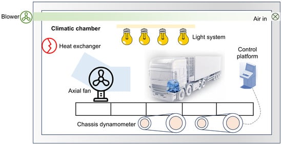
Figure 1.
Schematic diagram of experiment setup.
Figure 2 presents the electrical topology of the fuel cell-powered commercial vehicle used in this test. The stack was connected to the vehicle’s power distribution unit (PDU) via a boost DC/DC converter, supplying power either to the traction motor or charging the battery, with the power allocation determined by the energy management strategy. The auxiliary high-voltage output from the DC/DC converter of the fuel cell system powered components such as the PTC, hydrogen recirculation pump, and air compressor. During the fuel cell system startup phase, these auxiliary components relied on the battery to establish the necessary reaction conditions for the stack. Additionally, besides providing power to high-voltage components such as the air conditioning compressor and warm air PTC, the PDU also supplied power to the cooling fan, blower, water pump, and low-voltage battery through a buck DC/DC converter. The vehicle propulsion was entirely driven by the electric motor, and regenerative braking energy was recovered to charge the battery. To enable more precise energy consumption analysis, additional voltage and current sensors were installed at specific electrical interfaces.
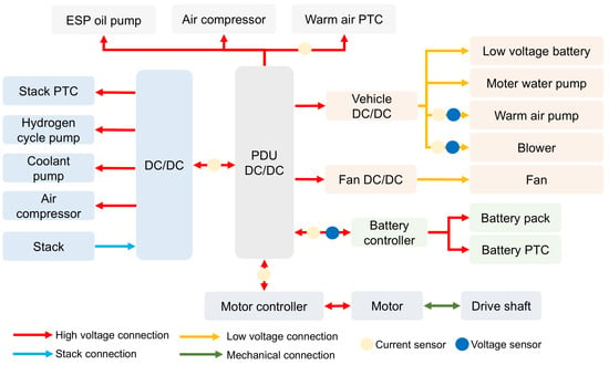
Figure 2.
The electrical topology of the fuel cell commercial vehicle and the arrangement of additional sensors during testing.
The integrated vehicle thermal management architecture is illustrated in Figure 3, comprising five primary circuits: the stack cooling loop, motor cooling loop, battery cooling loop, coolant circulation loop, and cabin heating loop. The thermal management systems for the stack, battery pack, and motor auxiliary components were independent, in which the stack radiator was positioned at the front of the vehicle to enhance cooling efficiency through direct airflow, while the battery pack and motor radiators were installed on the left and right sides of the vehicle, respectively, to optimize structural compactness. Within the air conditioning refrigerant circuit, gaseous refrigerant underwent compression in the compressor before flowing through the condenser, subsequently expanding through the thermal expansion valve and entering the evaporator to provide cabin air cooling. The fuel cell cooling loop facilitated heat exchange with ambient air via the stack radiator, with the waste heat recovery mode activating the heating core, PTC heater, heat exchanger, and circulation pump through electromagnetic valve control to maintain optimal operating temperature for both the stack and cabin compartment. To mitigate irreversible losses caused by flow resistance and heat exchange in the motor and controller cooling system, this thermal management system employed separate cooling branches: one integrating the DC/DC converter with the traction motor and another dedicated to the air compressor with its controller and motor control unit. For precise energy flow analysis, supplementary temperature and coolant flow sensors were installed at critical nodes. Additionally, to ensure the reliability of the sensor measurements, these sensors underwent precision calibration prior to installation. For voltage and current sensors, calibration was performed by connecting them to a high-precision power supply and load, followed by analyzing the measured values from tested sensors against feedback values from the high-precision equipment across varying current and voltage levels. Furthermore, temperature and coolant flow sensors were installed in a dedicated test bench for the fuel cell thermal management subsystem. This test bench enabled the precise control of heat generation power, coolant temperature, and flow rate. Calibration was achieved by comparing the measured values from the tested sensors with reference values obtained from high-precision temperature and flow sensors integrated within the test bench, under varying temperature and flow conditions.
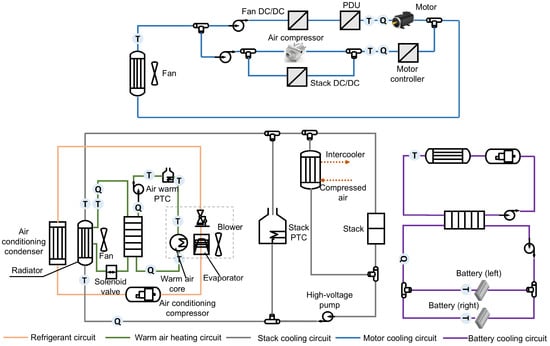
Figure 3.
Architecture and sensor distribution of thermal management system.
2.2. Experimental Conditions
The energy consumption testing and analysis of the commercial vehicle were conducted in accordance with the Chinese National Standard GB/T 27840-2021 [27]. The coasting resistance was configured based on the recommended values provided in appendix E of this standard. Specifically, the coasting resistance was set according to the requirements for both fully loaded and half-loaded mass conditions. The relevant formulas are presented below:
where and represent the full-load and half-loaded coasting resistance (N), respectively, including the vehicle rolling resistance, wind resistance, and internal resistance; V is the vehicle speed (km/h). To accurately evaluate the energy consumption of the fuel cell vehicle under low-temperature conditions, we examined several temperature environments (7 °C, °C, and °C) in accordance with standard requirements. Additionally, we performed dynamic testing based on the Chinese heavy-duty commercial vehicle driving cycle with a semi-trailer tractor (CHTC-TT), which incorporates diverse driving states (acceleration, deceleration, constant speed, and idling) across urban, suburban, and highway scenarios, rather than steady-state speed tests, to better replicate real-world operating conditions. Furthermore, comparative experiments with and without fuel cell waste heat recovery were conducted to thoroughly investigate its impact on overall vehicle energy consumption. This was achieved by controlling the heating circuit shutoff valve to regulate coolant circulation either through the stack radiator alone or through both the stack radiator and water-to-air heat exchanger simultaneously. The specific experimental test sequences are detailed in Table 2, where “seq” stands for the sequence number. It should be noted that considering the effect of the low temperature on the road adhesion coefficient, the coasting resistance was additionally multiplied by a factor of 1.1 for correction under sub-zero-temperature conditions.

Table 2.
Energy flow test conditions of commercial vehicle under different ambient temperatures and loading modes.
Prior to the commencement of testing, the test vehicle had to be placed in the environmental chamber according to the test conditions specified in Table 3 for thorough acclimatization, particularly in the sub-zero, low-temperature environment. The commercial vehicle employed in this study was a hybrid power system consisting of a fuel cell system and a lithium-ion battery pack. During actual operation, the power output of both the fuel cell system and the battery pack was governed by the energy management strategy. Consequently, in the CHTT-TT cycle test, variations in the initial battery SOC influenced the energy distribution and consumption between the fuel cell system and battery pack. Since this study primarily investigated the impact of waste heat recovery on energy utilization under low-temperature conditions, experiments were conducted at different temperatures and loads and with waste heat recovery enabled or disabled, while maintaining nearly identical initial conditions to ensure comparability. With this, the initial SOC of the battery pack was set to 50% for test Seq1 through to Seq7. Furthermore, to elucidate the effect of different initial SOC levels on the energy consumption of the fuel cell system, the battery initial SOC was adjusted to 70% in Seq8 using a charger. Moreover, the onboard hydrogen storage pressure was maintained above 10 MPa to ensure enough hydrogen supply during the test. Additionally, it was imperative to verify the absence of leaks in the air conditioning system pipelines and all connecting joints. Furthermore, the vehicle’s driving mode was set to economy mode, which prioritized the operation of the fuel cell within its optimal efficiency range to avoid low-load or overload conditions. Excess energy generated could be utilized to charge the battery pack. The cabin air conditioning was activated with a target temperature set at 31 °C. Meanwhile, during the testing process, the vehicle doors and windows remained closed, and bus data of the controller area network from the vehicle control unit and supplementary sensor data including temperature, flow rate, current, and voltage were recorded at a sampling frequency of 10 Hz.

Table 3.
Total and per-kilometer energy consumption under different conditions.
3. Results and Discussion
3.1. Energy Distribution
The analysis of fuel cell waste heat utilization under low-temperature conditions was primarily conducted through the energy flow depicted in Figure 4, which encompassed the energy delivered from the fuel cell system to the PDU (Stack-P), the energy supplied by the battery pack to the PDU (Battery-P), the charging energy received from the PDU (P-Battery), and the energy transferred from the PDU to the motor controller (P-Motor) along with the regenerative braking energy absorbed from the motor (Motor-P), including the PTC energy consumption (P-PTC), blower energy consumption (P-blower), and heating coolant pump energy consumption (P-Pump). As shown in Figure 5a, the motor supply energy, regenerative braking energy, and net motor energy consumption under different operating conditions demonstrated that the motor drive energy consumption increased naturally with the increase in load mass. For example, when the ambient temperature was 7 °C and the load increased from half load to full load, P-Motor rose from to . Furthermore, due to additional corrections made for coasting resistance at sub-zero temperatures, the driving energy consumption under both half-load and full-load conditions at sub-zero temperatures was higher than the test results at 7 °C. Moreover, the measured P-Motor at °C was greater than that at °C, which can be attributed to the increased viscosity of motor lubricant at the low temperature, resulting in higher bearing friction, increased mechanical losses, and consequently reduced motor operating efficiency.
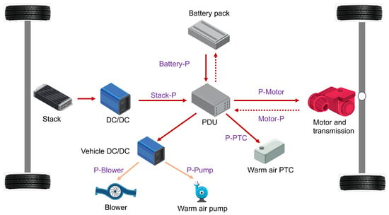
Figure 4.
Energy flow of key components for fuel cell waste heat utilization.
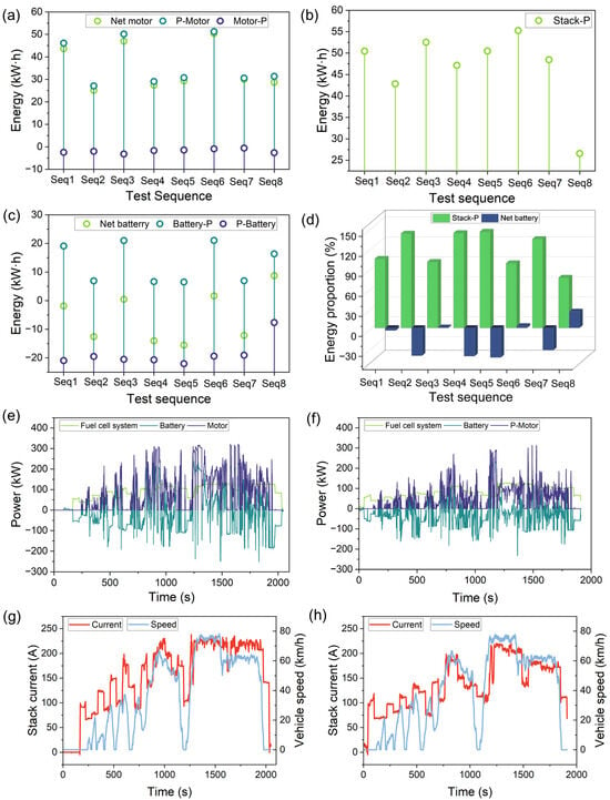
Figure 5.
Energy consumption under different test conditions: (a) motor energy consumption, (b) fuel cell system energy consumption, and (c) battery pack energy consumption. (d) Statistical results of energy proportion under different test conditions. Power distribution and stack current versus vehicle speed at 7 °C under (e) full-load conditions and (f) corresponding stack current and vehicle speed variations and (g) half-load conditions and (h) corresponding stack current and vehicle speed variations.
Figure 5b,c present the net output energy consumption of the fuel cell system along with the battery pack’s energy supply to the PDU and reverse charging energy from the PDU, respectively. Figure 5d illustrates the proportion of both the fuel cell system energy and net battery energy (Battery-P + P-Battery) relative to the total energy consumption (Stack-P + Battery-P + P-Battery). A negative value indicates that the battery achieved a net charging state upon completing the driving cycle. Several observations can be made from these results. First, these energy consumption patterns were determined by the energy management strategy and correlate with state parameters of both the vehicle and its components, including vehicle speed, load mass, battery SOC, ambient temperature, and fuel cell system status. Currently, practical energy management strategies primarily adopt deterministic rule-based strategies. Specifically, when the battery SOC is in the high state range, both the fuel cell and the power battery jointly supply energy, with the fuel cell contributing a reduced proportion. When the battery SOC is in the medium state range, the fuel cell and the power battery co-supply energy, with the fuel cell providing an intermediate proportion of energy, while a portion of the fuel cell’s output is allocated to recharge the battery. When the battery SOC is at a relatively low level, under conditions of low vehicle power demand, the fuel cell supplies the majority of the energy to ensure economic efficiency, with the power battery providing a minor portion. Conversely, under high vehicle power demand, the fuel cell delivers the entirety of the required energy while simultaneously recharging the power battery, thereby maintaining the battery SOC within the desired range. Based on this, when the initial battery SOC was maintained at approximately 50% at the beginning of tests (Seq1-Seq7), both the fuel cell system energy consumption and battery energy consumption exhibited an increasing trend with higher load mass. Moreover, to mitigate fuel cell accelerated degradation caused by the frequent power variation, the output power under half-load conditions was maintained at levels comparable to those under full-load operation (Figure 5e,f), with the stack current consistently operating within the 230 A range. Notably, the stack operating current did not drop to zero when vehicle speed reached zero (Figure 5g,h), resulting in reduced battery power output during half-load conditions while the surplus fuel cell generation charged the battery pack. Based on Seq8 test results, when the battery pack’s initial SOC reached approximately 70%, the energy management strategy tended to reduce the fuel cell output power to minimize hydrogen consumption. Compared with the initial SOC of 50%, the fuel cell system energy consumption decreased from to . Therefore, for the test vehicle in this study, regardless of whether it operated under half-load or full-load conditions, when the initial battery SOC was relatively low (e.g., starting at 50% SOC), the energy demand was primarily supplied by the fuel cell system while simultaneously charging the battery. Certainly, it will be necessary to adopt optimized predictive methods to achieve more rational power distribution in the future, ensuring not only lower overall energy consumption but also maximizing the lifespan of both the fuel cell and battery. Furthermore, as the ambient temperature decreases, the fuel cell system energy consumption clearly increases, primarily because the initial startup process requires the stack to operate within the concentration polarization region to enhance heat generation efficiency, thereby enabling rapid temperature rise in the coolant and preventing cold-start failure.
The energy consumption of the warm air PTC, warm air water pump, and blower under different test conditions along with the proportion of warm air PTC consumption to total energy consumption are presented in Figure 6a and Figure 6b, respectively, where a distinct increase in the energy consumption ratio of the warm air PTC is observed with decreasing ambient temperature, consistent with the greater energy demand for warm air circuit in the low-temperature environment. Moreover, deactivating the fuel cell waste heat recovery system resulted in significant increases from 1.13% to 9.95% at −7 °C and from 3.59% to 13.78% at −25 °C. Additionally, Figure 6c,d (with varying test initiation times under different conditions) demonstrate the power variation in warm air PTC with/without waste heat recovery at −7 °C and −25 °C, revealing that the warm air PTC primarily supported the warm air circuit heating during initial operation due to low coolant temperature of the stack but ceased operation after the stack reached thermal stability, whereas without waste heat recovery, the warm air PTC exhibited periodic activation due to water temperature fluctuations, leading to additional energy consumption. Figure 6e presents the warm air PTC power distribution under various test conditions, demonstrating that the warm air PTC remained predominantly deactivated during the test process, except for Seq5 and Seq8 where waste heat recovery was disabled. Table 3 also presents the total energy consumption under various test conditions, along with the calculated driving mileage and per-kilometer energy consumption statistics. Further analysis revealed that the energy consumption per kilometer increased with rising ambient temperature and load capacity. Moreover, closing the waste heat recovery system also led to increased per-kilometer energy consumption.
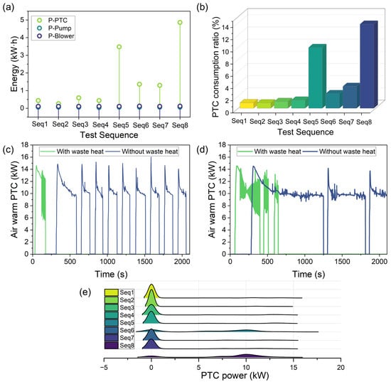
Figure 6.
(a) Energy consumption of P-PTC, P-Pump, and P-Blower under different test conditions. (b) Ratio of warm air PTC energy consumption to total energy consumption. Power variation in warm air PTC with and without fuel cell waste heat utilization under half-load conditions at (c) −7 °C and (d) −25 °C, respectively. (e) Distribution of warm air PTC power under various testing conditions.
3.2. Analysis of Thermal Management System
An effective thermal management system is a coupled and complex system composed of multiple subsystems. The system achieves thermal management function through coordinated operation among subsystems, enabling adaptation to changes in ambient environmental and operating conditions. The characteristics of thermal management systems significantly impact the performance and energy consumption levels of fuel cell heavy-duty commercial vehicles. This study evaluated the energy consumption of the tested heavy-duty truck through analysis of key components and systems related to fuel cell waste heat utilization.
3.2.1. Fuel Cell Thermal Management Subsystem
Temperature is a critical operational condition and control objective for fuel cells. Excessively high temperature, particularly under low current density conditions, can induce membrane drying failure, which reduces proton conductivity. Prolonged membrane drying may lead to irreversible degradation phenomena such as cracks, localized hotspots, and perforation, ultimately resulting in the accelerated performance decay of a fuel cell. Moreover, excessively low operating temperature in fuel cells frequently induces water flooding phenomena, which obstruct porous media and flow channels, thereby impeding reactant transport to active reaction sites. Prolonged water accumulation accelerates component degradation through multiple mechanisms: the gas diffusion layer and catalyst layer experience corrosion under reactant starvation conditions, while platinum catalyst dissolution occurs due to sustained hydrodynamic erosion. Furthermore, the polymer membrane undergoes swelling during extended flooding events, with cumulative swelling stresses ultimately leading to the formation of pinholes or cracks. To this end, maintaining the fuel cell temperature within an appropriate range is of critical importance. In terms of the low-temperature PEM fuel cell system, the recommended operating temperature range typically falls between 60 °C and 90 °C, with temperature requirements increasing proportionally with current density. To ensure uniform reaction kinetics across the cell, the temperature differential between coolant inlet and outlet should generally be maintained within 10 °C. It is noted that the operating temperature of the stack could not be directly obtained through the fuel cell system controller due to the unavailability of the communication protocol for the tested commercial vehicle. Furthermore, the compact arrangement of the fuel cell system prevented the installation of temperature sensors directly at the coolant inlet and outlet ports of the stack within the limited available space. The temperature sensor at the radiator inlet was positioned as close as possible to the stack coolant outlet to approximate the temperature variation trend at the stack outlet. To this end, since this study primarily focuses on fuel cell waste heat recovery, subsequent analysis will concentrate on temperature variations in key waste heat recovery components.
Figure 7 presents the fuel cell system output, cooling circuit temperature, and flow rate under various test conditions, where and denote the stack radiator inlet and outlet temperature, respectively; indicates the stack-side outlet temperature of the waste heat recovery heat exchanger. stands for the stack-side coolant flow rate in the waste heat recovery heat exchanger, and corresponds to the stack flow rate. The test results at 7 °C under both full-load and half-load conditions (Figure 7a,b) demonstrate that the coolant temperature at the stack radiator inlet was consistently maintained below 90 °C, though the average during half-load operation was slightly lower than that under full-load conditions due to reduced power output. During waste heat recovery operation, the coolant flow diverged into two parallel paths: one portion circulated through the stack radiator with forced convective cooling by fans, while the remaining portion entered the waste heat recovery heat exchanger branch to heat the cabin air-conditioning system coolant, resulting in a relatively low stabilized temperature range of 30–60 °C at the stack radiator outlet after flow recombination. The test results under °C conditions for full load, half load, and half load without waste heat recovery are shown in Figure 7c, Figure 7d, and Figure 7e respectively, with the radiator inlet temperature consistently maintained below 90 °C, demonstrating that the thermal management strategy effectively prevented system overheating. Comparative analysis of Figure 7d,e reveals that when the waste heat utilization shut-off valve was closed, the stack-side coolant flow rate in the heat exchanger branch dropped to zero. Hence, the outlet water temperature of the stack-side heat exchanger was less influenced by heat transfer from the stack cooling circuit, resulting in a gradual temperature increase from 7 °C to 59 °C over approximately 166 s, followed by periodic fluctuations between 56 °C and 73 °C upon stabilization. This fluctuation correlated with the warm air heating circuit temperature variation, primarily attributed to the intermittent operation of the warm air PTC. In contrast, waste heat recovery activation significantly enhanced thermal interaction between and the stack cooling circuit, yielding a faster temperature increase from 7 °C to 59 °C in about 99 s, and its variation trend aligned closely with that of the radiator inlet temperature . Furthermore, after the waste heat recovery function was deactivated, the heat from the waste heat exchanger branch and the warm air circuit could not be effectively transferred to the stack radiator outlet. The radiator outlet temperature remained relatively low throughout the testing process, not exceeding 20 °C, and the rate of temperature increase was slow. Specifically, it took approximately 103 s for the temperature to rise from the initial °C to the first peak of °C. On the other side, when waste heat recovery was enabled, the stabilized could be maintained above 30 °C, and the time required to increase from °C to °C was reduced to approximately 67 s. With this, the deactivation of waste heat recovery led to an excessively low outlet temperature in the fuel cell stack radiator, which could result in a low coolant temperature at the stack inlet; a such phenomenon increased the risk of flooding within the fuel cell stack and exacerbated the temperature differential between the inlet and outlet. These results indicate that activating waste heat recovery not only decreased the proportion of energy consumption attributed to the warm air PTC but also contributed to superior fuel cell thermal management. Consistent conclusions were drawn from the results shown in Figure 7f–h, which show that the radiator inlet temperature remained effectively controlled within the optimal range, while the radiator outlet temperature under deactivated waste heat recovery (Figure 7h) was markedly lower than measurement taken during active waste heat recovery operation. Figure 8 presents the statistical distribution of and during the testing process under different test sequences. It can be more clearly observed that with the heat recovery system activated, both the radiator outlet temperature and heat exchanger outlet temperature demonstrated significantly higher values.
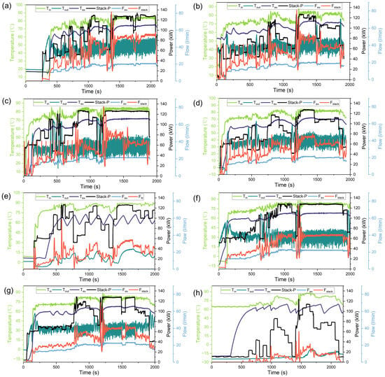
Figure 7.
Stack-P, cooling circuit temperature and flow variations under different test conditions: (a) Seq1; (b) Seq2; (c) Seq3; (d) Seq4; (e) Seq5; (f) Seq6; (g) Seq7; (h) Seq8.

Figure 8.
Statistical distribution results of (a) and (b) under different test conditions.
3.2.2. Warm Air Subsystem
The test results of the warm air subsystem under full and half-load conditions at 7 °C are presented in Figure 9a,b, where represents the outlet temperature of the warm air core, denotes the outlet temperature of the warm air PTC, and indicates the coolant flow rate of the warm air pump. As can be seen, the coolant flow rate remained relatively stable with minor fluctuations around 20 L/min, where the coolant underwent forced convective heat transfer with air blown by the blower through the warm air core to provide cabin heating. During the initial test phase, the warm air PTC heating was necessary due to the low temperature of the stack-side coolant from the waste heat recovery heat exchanger. As shown in the example given in Figure 9a, the initial warm air PTC power was relatively high but gradually decreased as the warm air core outlet temperature increased, with the PTC deactivating when reached approximately °C. However, the PTC reactivated when subsequently dropped below °C to meet additional heating requirements. Notably, the PTC remained inactive once the stack coolant temperature increased sufficiently. These observations demonstrate that relying exclusively on fuel cell waste heat recovery may be inadequate to meet cabin heating demand under these operating conditions. The experimental results at °C under full load, half load, and half load without waste heat recovery conditions are, respectively, illustrated in Figure 9c–e. When waste heat recovery was enabled, the warm air PTC was activated during the initial phase with a low stack coolant temperature, demonstrating prolonged operation duration compared to that in the 7 °C test cases. As previously noted, the disabled waste heat recovery condition required more frequent PTC activation cycles to maintain adequate cabin heating, consequently increasing auxiliary power consumption and adversely affecting the energy consumption ratio of the warm air PTC. Similar operational characteristics were observed in the °C testing condition, where extended PTC operation time was necessary to ensure that the heating coolant temperature reached the required level during the initial test phase.
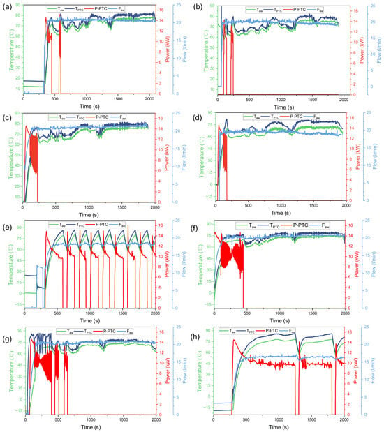
Figure 9.
Outlet temperature of warm air PTC, warm air core, PTC power, and flow rate of warm air pump under different test conditions: (a) Seq1; (b) Seq2; (c) Seq3; (d) Seq4; (e) Seq5; (f) Seq6; (g) Seq7; (h) Seq8.
3.2.3. Cabin Temperature Response
The measured cabin temperature profiles under different test conditions are presented in Figure 10, where represents the air outlet temperature at the driver’s foot vent (closely correlated with the warm air core temperature) and denotes the actual footwell temperature at the driver position. The results clearly demonstrate an inverse relationship between ambient temperature and cabin temperature. As can be seen, could only reach approximately 20 °C at the °C ambient temperature, whereas at the 7 °C ambient temperature, the climate control system maintained above 40 °C. It should be noted that the current ventilation and air conditioning system was operated in manual (open-loop) control mode with fixed airflow rates corresponding to predetermined target temperatures. Future implementation of automatic temperature control with closed-loop feedback regulation could potentially optimize thermal comfort while reducing overall vehicle energy consumption through more sophisticated control algorithms.
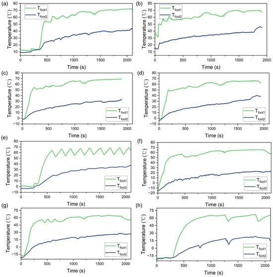
Figure 10.
Cabin temperature under different test conditions: (a) Seq1; (b) Seq2; (c) Seq3; (d) Seq4; (e) Seq5; (f) Seq6; (g) Seq7; (h) Seq8.
3.3. Discussion
This study investigated the energy and thermal response of key components in a fuel cell system and battery hybrid-powered commercial vehicle under varying ambient temperatures, load conditions, and waste heat recovery modes. However, several limitations remain to be addressed. For instance, due to constraints on testing time and equipment scheduling, each test sequence was conducted only once, potentially introducing random deviations. To enhance the reliability of the results, future studies should include repeated tests for each sequence. Additionally, the experimental design could be further refined by incorporating a more comprehensive test matrix that considers finer variations in ambient temperature, initial battery SOC, and waste heat recovery modes to better represent the real operational conditions of fuel cell commercial vehicles and highlight the role of waste heat recovery. Moreover, the current findings are primarily based on experimental measurements, and due to communication protocol limitations, critical parameters from the fuel cell system, battery pack, and motor could not be obtained. To enable more accurate and detailed energy flow and thermal load analysis, further acquisition of these key parameters is necessary, along with the model development for the fuel cell system, battery pack, drive motor, and vehicle dynamics. Such models would facilitate a more quantitative assessment of the impact of waste heat recovery on overall energy consumption and thermal management. Regarding cabin temperature control, the current rule-based strategy could be enhanced by employing machine learning to predict future fuel cell temperature and cabin heating demand, combined with optimization methods to improve the control of the warm air PTC, coolant pump, and fuel cell temperature, thereby reducing auxiliary energy consumption while meeting cabin heating requirements. On the other hand, the experimental results indicate that activating waste heat recovery in low-temperature environments benefits radiator outlet temperature regulation, which may help mitigate excessive coolant temperature differentials and flooding fault in the stack. Future work should also include repeated comparative experiments with and without waste heat recovery, as well as accelerated stress tests under low-temperature conditions, accompanied by fuel cell performance characterization through polarization curves, hydrogen crossover measurement, and impedance spectrum measurement to evaluate the influence of waste heat recovery on fuel cell durability. Furthermore, the current analysis focuses primarily on cabin heating via heat exchanger-based waste heat recovery. A more systematic approach integrating heat pumps for cabins, battery pack, and motor thermal management should be explored. Lastly, incorporating waste heat recovery for heating introduces additional components such as temperature sensors, heat exchangers, and piping, inevitably increasing system cost, volume, and mass power density. Future optimization of thermal management system component selection, layout, and structural design based on experimental and simulation results is essential to minimize cost and spatial challenges.
4. Conclusions
In this study, energy flow experiments were conducted on a 49-ton fuel cell commercial heavy-duty truck equipped with waste heat recovery capability under various environmental temperatures, load conditions, and waste heat recovery settings. The analysis focused on the energy consumption and distribution of components related to fuel cell waste heat recovery, as well as the temperature response of key thermal management system components, to comprehensively evaluate the waste heat utilization capability of fuel cell vehicles. Experimental results revealed that the energy consumption of both the fuel cell and battery was related to the initial battery SOC, as determined by the energy management strategy, but overall, the total energy consumption increased with decreasing environmental temperature and increasing load. Additionally, at °C and °C, when the waste heat utilization function was deactivated, the proportion of PTC heating power consumption increased from 1.13% to 9.95% and from 3.59% to 13.78% of the total energy consumption, respectively. Therefore, the fuel cell waste heat utilization function significantly affected the proportion of warm air PTC energy consumption, particularly in extremely low-temperature environments. Furthermore, the coolant temperature at the fuel cell radiator inlet remained stable within 90 °C, and with waste heat recovery activated, the radiator outlet temperature could reach higher values during the test, reducing the risk of stack flooding faults. Future studies should incorporate a more comprehensive experimental matrix with repeated tests and develop models of key components to enable detailed energy flow and thermal load analysis. Additionally, future works should integrate heat pump technology to achieve thermal management system design and integration for waste heat utilization, combined with intelligent algorithms to optimize thermal management control, thereby further improving energy utilization and the environmental adaptability of fuel cell vehicles.
Author Contributions
Conceptualization, F.L. and H.Y.; Methodology, F.L., Q.Z., Z.Z. and X.Z.; Validation, Z.Z. and H.D.; Writing—original draft preparation, F.L., H.Y. and K.F.; Writing—review and editing, F.L., H.Y., X.Z., K.F. and D.D.; Resources, F.L. and D.D. All authors have read and agreed to the published version of the manuscript.
Funding
This work was supported by National Key Research and Development Program of China (2023YFB4004500).
Data Availability Statement
Data are available on request from the authors.
Conflicts of Interest
Authors Fujian Liu and Zhichao Zhao were employed by the company China Automotive Engineering Research Institute Co., Ltd. The remaining authors declare that the research was conducted in the absence of any commercial or financial relationships that could be construed as a potential conflict of interest.
References
- Duan, X.; Feng, L.; Liu, H.; Jiang, P.; Chen, C.; Sun, Z. Experimental investigation on exhaust emissions of a heavy-duty vehicle powered by a methanol-fuelled spark ignition engine under world Harmonized Transient Cycle and actual on-road driving conditions. Energy 2023, 282, 128869. [Google Scholar] [CrossRef]
- Aletras, N.; Broekaert, S.; Bitsanis, E.; Fontaras, G.; Samaras, Z.; Ntziachristos, L. Energy management algorithm based on average power demand prediction for plug-in hybrid electric trucks. Energy Convers. Manag. 2024, 299, 117785. [Google Scholar] [CrossRef]
- Burchart, D.; Przytuła, I. Review of Environmental Life Cycle Assessment for Fuel Cell Electric Vehicles in Road Transport. Energies 2025, 18, 1229. [Google Scholar] [CrossRef]
- Hegde, S.; Wörner, R.; Shabani, B. Automotive PEM fuel cell catalyst layer degradation mechanisms and characterisation techniques, Part I: Carbon corrosion and binder degradation. Int. J. Hydrogen Energy 2025, 118, 268–299. [Google Scholar] [CrossRef]
- Huang, L.; Zhang, X.; Jiang, Y.; Dong, S.; Huang, R.; Liao, H.; Tang, S. Degradation analysis of dynamic voltage response characteristics of proton exchange membrane fuel cells for health evaluation under dynamic load. Appl. Energy 2025, 389, 125741. [Google Scholar] [CrossRef]
- Tan, X.; Sun, A.; Su, T. Enhanced electrochemical performance of proton exchange membrane fuel cell through optimal bolt configuration design. Appl. Energy 2025, 378, 124761. [Google Scholar] [CrossRef]
- Song, D.; Wu, Q.; Zeng, X.; Zhang, X.; Qian, Q.; Yang, D. An integrated thermal management system for fuel cell vehicles based on collaborative control. Appl. Therm. Eng. 2025, 264, 125500. [Google Scholar] [CrossRef]
- Yan, S.; Yang, M.; Sun, C.; Xu, S. Liquid Water Characteristics in the Compressed Gradient Porosity Gas Diffusion Layer of Proton Exchange Membrane Fuel Cells Using the Lattice Boltzmann Method. Energies 2023, 16, 6010. [Google Scholar] [CrossRef]
- Togun, H.; Basem, A.; Abdulrazzaq, T.; Biswas, N.; Abed, A.M.; dhabab, J.M.; Chattopadhyay, A.; Slimi, K.; Paul, D.; Barmavatu, P.; et al. Development and comparative analysis between battery electric vehicles (BEV) and fuel cell electric vehicles (FCEV). Appl. Energy 2025, 388, 125726. [Google Scholar] [CrossRef]
- Yadav, S.; Assadian, F. Robust Energy Management of Fuel Cell Hybrid Electric Vehicles Using Fuzzy Logic Integrated with H-Infinity Control. Energies 2025, 18, 2107. [Google Scholar] [CrossRef]
- Oladosu, T.L.; Pasupuleti, J.; Kiong, T.S.; Koh, S.P.J.; Yusaf, T. Energy management strategies, control systems, and artificial intelligence-based algorithms development for hydrogen fuel cell-powered vehicles: A review. Int. J. Hydrogen Energy 2024, 61, 1380–1404. [Google Scholar] [CrossRef]
- Zhou, Y.; Guo, Y.; Yang, F.; Chen, B.; Ma, R.; Ma, R.; Jiang, W.; Bai, H. Speed-prediction-based hierarchical energy management and operating cost analysis for fuel cell hybrid logistic vehicles. Appl. Energy 2025, 390, 125843. [Google Scholar] [CrossRef]
- Yang, S.; Sun, H.; Liu, Z.; Deng, C.; Xie, N. Process modeling and analysis of a combined heat and power system integrating solid oxide fuel cell and organic Rankine cycle for poultry litter utilization. Appl. Therm. Eng. 2024, 236, 121897. [Google Scholar] [CrossRef]
- Wang, Y.; Zeng, Z.; Wang, T.; Che, Z. Dynamic simulation and optimization of a residential proton exchange membrane fuel cell (PEMFC) combined heat and power (CHP) system. Energy 2025, 319, 134865. [Google Scholar] [CrossRef]
- Li, R.; Wu, Z.; Luo, J.; Zou, Z.; Huang, Y.; Zhou, X.; He, G. Development and validation of a 200 kW PEM fuel cell system with a novel PCM-integrated waste heat recovery strategy. J. Energy Storage 2025, 122, 116697. [Google Scholar] [CrossRef]
- Li, J.; Li, J.; Xiao, L.; Zhang, H. Unlocking the potentials using humidifier-dehumidifier for proton exchange membrane fuel cell waste heat recovery. Renew. Energy 2024, 237, 121571. [Google Scholar] [CrossRef]
- Yang, Y.; Luo, C.; Zhou, C.; He, M. Waste heat utilization of low-temperature proton exchange membrane fuel cell refrigerated vehicle with integrated absorption-compression refrigeration system. Appl. Therm. Eng. 2025, 269, 126103. [Google Scholar] [CrossRef]
- Zhang, N.; Lu, Y.; Kadam, S.; Yu, Z. A fuel cell range extender integrating with heat pump for cabin heat and power generation. Appl. Energy 2023, 348, 121600. [Google Scholar] [CrossRef]
- Lee, H.; Lee, D.; Kim, Y. Heating performance of a coolant-source heat pump using waste heat from stack and electric devices in fuel cell electric vehicles under cold conditions. Energy Convers. Manag. 2022, 252, 115092. [Google Scholar] [CrossRef]
- Park, Y.; Kim, J.; Oh, J.; Han, U.; Lee, H. Multi-objective optimization of an offset strip fin heat exchanger for waste heat recovery in electric vehicles. Appl. Therm. Eng. 2023, 228, 120533. [Google Scholar] [CrossRef]
- Zhu, Z.; Wang, X.; Jiang, W.; Wang, W.; Li, C.; Li, S. A coupling and multi-mode thermal management system design and control for high-power fuel cell vehicles with utilizing waste heat. Energy Convers. Manag. 2025, 328, 119590. [Google Scholar] [CrossRef]
- Colmenar-Santos, A.; Alberdi-Jiménez, L.; Nasarre-Cortés, L.; Mora-Larramona, J. Residual heat use generated by a 12 kW fuel cell in an electric vehicle heating system. Energy 2014, 68, 182–190. [Google Scholar] [CrossRef]
- Campíñez-Romero, S.; Colmenar-Santos, A.; Pérez-Molina, C.; Mur-Pérez, F. A hydrogen refuelling stations infrastructure deployment for cities supported on fuel cell taxi roll-out. Energy 2018, 148, 1018–1031. [Google Scholar] [CrossRef]
- Sun, W.; Yi, F.; Hu, D.; Zhou, J. Research on matching design method of waste heat reuse system of fuel cell vehicle considering system energy consumption and waste heat exchange rate. Int. J. Energy Res. 2021, 45, 5470–5485. [Google Scholar] [CrossRef]
- Quan, R.; Yang, Z.; Qiu, Z.; Li, X.; Chang, Y. Thermal performance simulation and numerical analysis of a fuel cell waste heat utilization system for automotive application. Appl. Therm. Eng. 2024, 252, 123719. [Google Scholar] [CrossRef]
- Feng, R.; Yu, J.; Zhao, Z.; Hua, Z.; He, J.; Shu, X. Performance and energy-consumption evaluation of fuel-cell hybrid heavy-duty truck based on energy flow and thermal-management characteristics experiment under different driving conditions. Energy Convers. Manag. 2024, 321, 119084. [Google Scholar] [CrossRef]
- GB/T 27840-2021. Available online: https://std.samr.gov.cn/gb/search/gbDetailed?id=CE1E6A1DD5B458F6E05397BE0A0A68DF (accessed on 28 April 2025).
Disclaimer/Publisher’s Note: The statements, opinions and data contained in all publications are solely those of the individual author(s) and contributor(s) and not of MDPI and/or the editor(s). MDPI and/or the editor(s) disclaim responsibility for any injury to people or property resulting from any ideas, methods, instructions or products referred to in the content. |
© 2025 by the authors. Licensee MDPI, Basel, Switzerland. This article is an open access article distributed under the terms and conditions of the Creative Commons Attribution (CC BY) license (https://creativecommons.org/licenses/by/4.0/).