1. Introduction
With the rapid growth of China’s economy, electricity demand has been continuously rising, leading to the ongoing expansion of the grid structure. In this process, the complexity and scale of the power system have made the issue of short-circuit currents increasingly prominent. Short-circuit current refers to the current that flows through the fault point when a short-circuit fault occurs in the power system, and its magnitude directly affects the safe and stable operation of electrical equipment. With the increase in the number of generating units and the extension of transmission lines, particularly the integration of large generating equipment, the risk of excessive short-circuit currents has become more apparent. This may lead to equipment damage and the instability of the power system, posing severe challenges for protection device design and power system operation. In AC power grids, a rapid increase in short-circuit currents can prevent protection devices from operating correctly within the set time, resulting in cascading failures within the power system. An excess of short-circuit currents also increases safety hazards in the system, raising the likelihood of accidents. Thus, there is an urgent need to implement effective measures to limit short-circuit currents to address this issue. By effectively reducing short-circuit currents through these measures, the safe and reliable operation of the power system can be ensured, providing a solid guarantee for the sustainable development of the economy and the efficient utilization of energy.
For many years, scholars both domestically and internationally have conducted extensive research on how to solve the problem of excessive short-circuit currents.
Surya, A. et al. suggest that increasing the impedance value of transformers to 45% can effectively reduce short-circuit currents in high-voltage power systems, thereby minimizing the risk of transformer damage [
1]. Li, J. et al. propose that transformers with variable impedance can reduce short-circuit currents and overvoltages through novel suppression measures, enhancing the safety and economic value of the power grid [
2]. Xu, C. et al. have put forward a current-limiting strategy for modular inverter systems under asymmetric short-circuit faults, which is simpler and more effective than existing methods, ensuring reliable power supply [
3]. Varetsky, Y. et al. point out that current-limiting reactors in industrial power grids may be damaged due to peak currents, necessitating the careful selection of grid locations, equipment start-up currents, and potential grid configurations [
4]. Gouda, O. et al. introduced a novel air-core current-limiting reactor that effectively limits fault currents in medium- and low-voltage systems without causing harmonic issues [
5]. Ren, H. et al. argue that current-limiting reactors can effectively limit short-circuit currents in 500 kV power systems but may increase the transient recovery voltage steepness during circuit breaker interruptions [
6]; they also proposed that adding current-limiting reactors on 500 kV transmission lines can reduce temporary overvoltages by altering positive- and zero-sequence impedance parameters [
7]. Wang, P. et al. introduced a DC solid-state current limiter with adaptive current-limiting capability, which effectively suppresses the rapid rise in DC fault currents in power systems, reducing the impact on the dynamic characteristics of reactors [
8]. Wang, Z. et al. contend that current-limiting reactors can effectively reduce peak-to-peak short-circuit fault currents in DC distribution systems, minimizing damage and ensuring system safety [
9].
Lyu, H. et al. proposed an improved hybrid DC circuit breaker with adaptive fault current-limiting capabilities, which effectively restrains fault currents, maintains system stability, and reduces requirements for protection and surge arrester capacity [
10]. Han, B. et al. proposed a dynamic breaker that combines changes in system structure with dynamically adjusting system topology during faults in Reference [
11]. In Reference [
12], Wang, Z. et al. proposed a hybrid direct-current circuit breaker with current-limiting capabilities, which exhibits better breaking performance and lower costs compared to traditional topologies, solving the problem of excessive short-circuit currents in branch grids. The fault current limiter (FCL) is a novel current-limiting solution. Wu, S. studied several representative fault current limiters, including those under development, with a focus on Thyristor-Protected Series Capacitor (TPSC)-based short-circuit current limiters (SCCLs). The research also introduced a demonstration project of fault current limiters in the East China 500 kV grid, detailing the main circuit diagram and using overvoltage protection control, as well as summarizing the development trends of fault limiters in the literature [
13]. In Reference [
14], Yan, Z. researched TPSC-based short-circuit current limiters with externally connected series reactors, effectively addressing excessive short-circuit currents in high-voltage transmission systems, enhancing reliability and availability. Ming, Z. believes that fault current limiters provide zero or low impedance under normal conditions and high-impedance during short-circuit faults, offering a multifunctional solution for various applications [
15]. In Reference [
16], Zhang, Q. et al. proposed an AC fast-recovery superconducting fault current limiter, which can effectively suppress short-circuit currents and increase system stability by over three times. Amini, M. et al. proposed a novel fault current limiter based on hollow variable series reactors, which can effectively limit fault currents in a short time while minimizing voltage drop and reactive power loss during normal operation [
17]. In Reference [
18], Mujie, Z. et al. proposed that a 550 kV fault current limiter with fast switching and a large capacity can effectively limit short-circuit currents, improving the distance protection performance of power grid lines. Akin, F. et al. contend that hollow reactors in solid-state fault current limiters can effectively limit fault currents during grid failures while carrying nearly the entire current of the network under normal conditions [
19]. Zhang, K. et al. argue that fast-switching fault current limiters can effectively limit short-circuit currents in extra-high-voltage transmission lines without significantly impacting the overvoltage during automatic reclosing [
20]. Meanwhile, in Reference [
21], Gan, Y. et al. also pointed out that fault current limiters and flexible current-limiting technologies show broad prospects in AC power supply systems, but further research on equipment topology and configuration is needed to improve economic viability.
Regarding the topic of how to limit short-circuit currents in large power grids, we have previously conducted some research and published two manuscripts. In Ref. [
22], we briefly described the advantages and disadvantages of more than a dozen current-limiting measures, as well as their applicable conditions and installation locations, focusing on the optimal selection methods when multiple solutions are available for the same short-circuit current exceedance issue [
22]. Subsequently, we shifted our research focus to the current-limiting measures themselves, categorizing the measures outlined in Ref. [
22] into two main categories based on structural changes to the power grid and the renovation of grid equipment. Therefore, in Ref. [
23], we provided a detailed discussion of the principles and related simulations of current-limiting measures that involve changing the grid structure, while the current manuscript addresses the other major category of current-limiting measures, namely, measures related to renovating grid equipment, including principles and simulation studies, to complete our research framework.
In practical engineering, the selection of short-circuit current-limiting measures is often based on engineering experience. However, there is relatively little systematic research that thoroughly examines the principles, advantages, and disadvantages of various measures, specifies the applicable conditions for each, and conducts actual grid simulations to validate their effectiveness in limiting current.
This paper focuses on researching measures and methods to limit short-circuit currents through the renovation of grid equipment. It provides a detailed analysis of the working principles, advantages, disadvantages, and applicable conditions of each measure, which is of significant importance for the evaluation and selection of current-limiting measures based on actual engineering needs. Furthermore, for each current-limiting measure, real grid data are used for simulation analysis, allowing for a comparison of short-circuit currents before and after the implementation of the limiting measures. This clearly illustrates the effectiveness of the current-limiting measures studied in this paper. Additionally, this paper elaborates in detail on the existing gaps in current research and conducts simulations, contributing valuable insights into addressing the issue of exceeding short-circuit current limits.
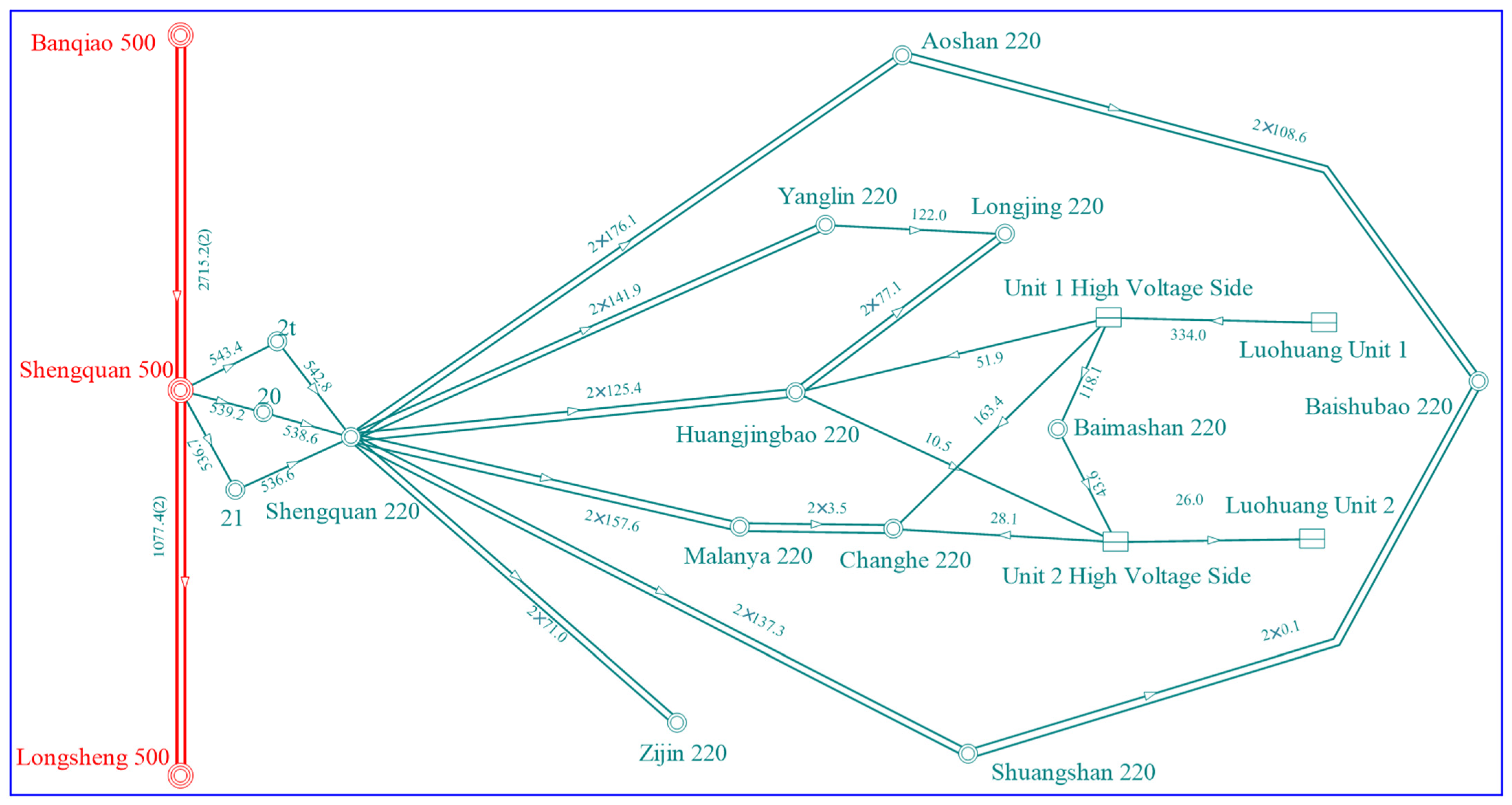
This paper primarily focuses on the issue of exceeding short-circuit current limits in the 500–220 kV high- and low-voltage electromagnetic ring networks present in China’s large power grids. In
Section 2, the composition and control principles of short-circuit currents in the grid are examined.
Section 3 places emphasis on analyzing the mechanisms, applicable conditions, advantages, and disadvantages of short-circuit current-limiting measures that involve renovating grid equipment. In
Section 4, a simulation analysis of the current-limiting effects of each short-circuit current-limiting measure, using a specific grid as a case study, is conducted. Finally,
Section 5 presents a summary of the research findings and discusses the limitations of this study.
2. Principle of Short-Circuit Current Control
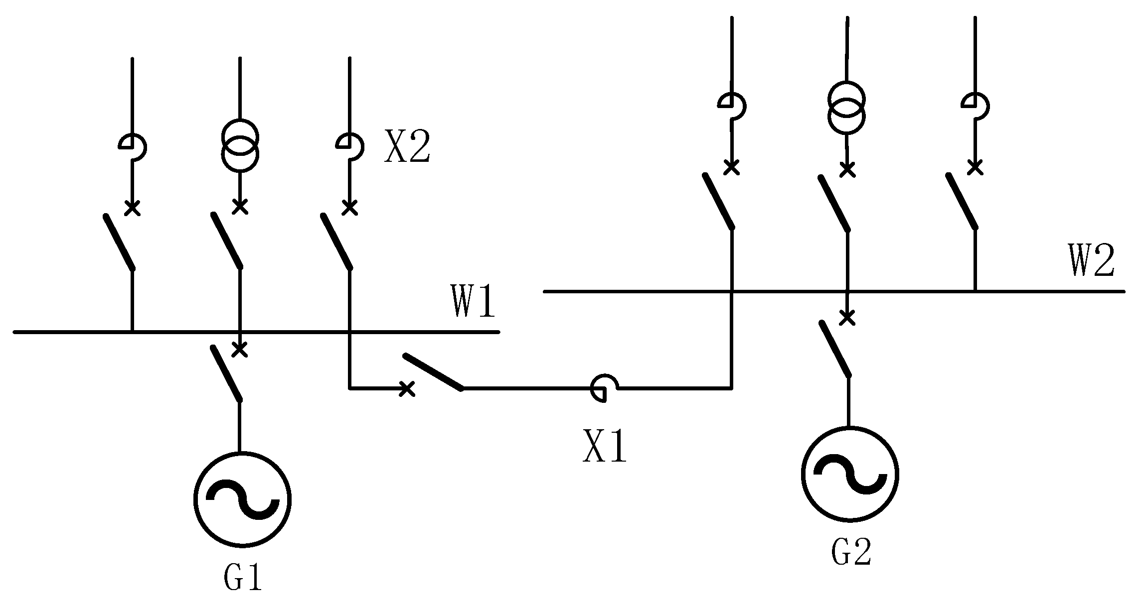
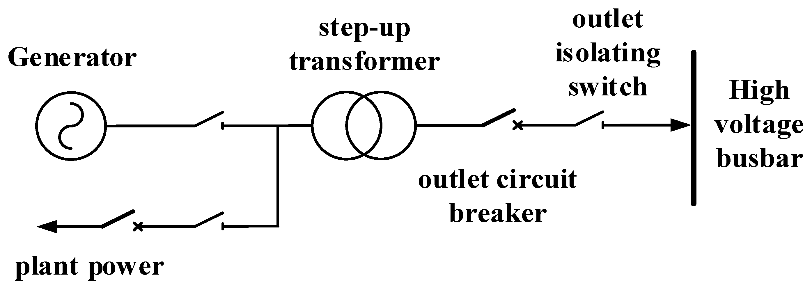
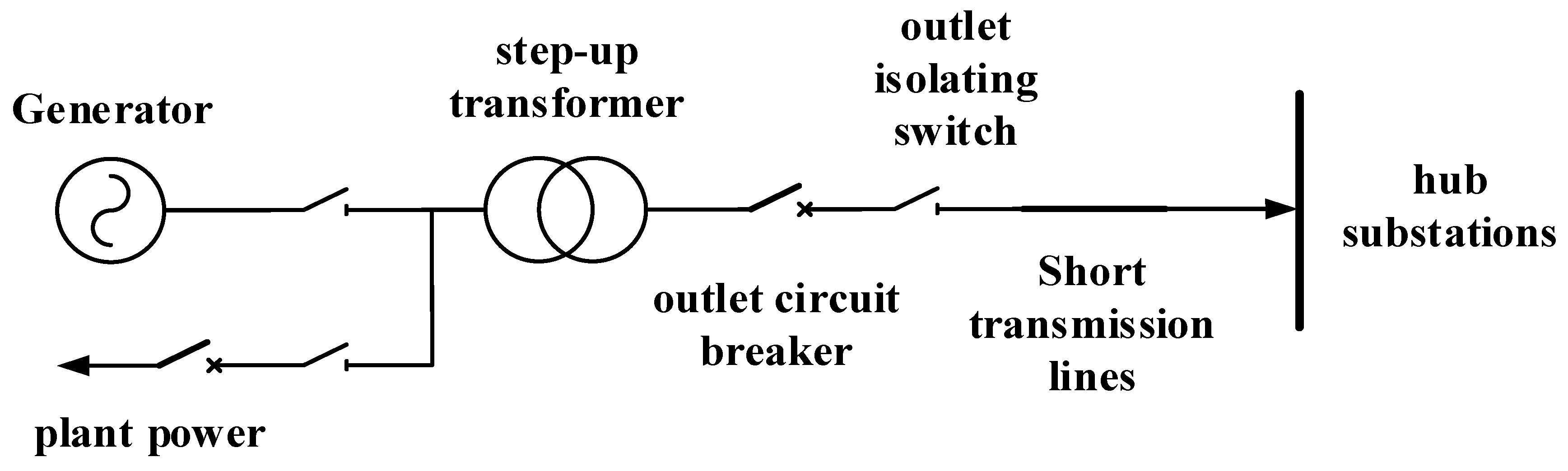
In mainland China, common issues of excessive short-circuit currents often occur in the 500–220 kV electromagnetic ring network, as illustrated in the schematic diagram shown in
Figure 1.
As the most severe type of short-circuit fault, it is essential to study the control principles of three-phase short-circuit currents. The magnitude of three-phase short-circuit currents depends on the self-impedance of the short-circuit point, which physically represents the electrical distance between the short-circuit point and other points in the network. The tighter the network structure, the smaller the node self-impedance and the electrical distance, resulting in higher levels of short-circuit currents; conversely, the opposite is also true.
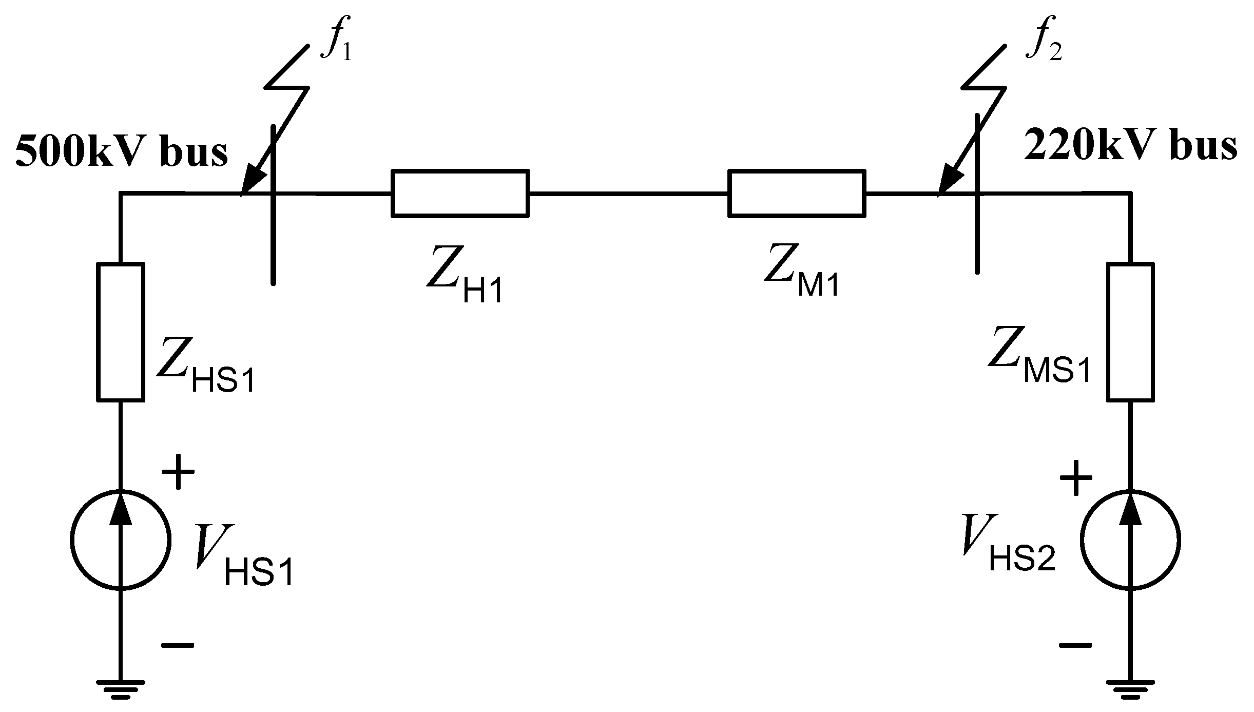
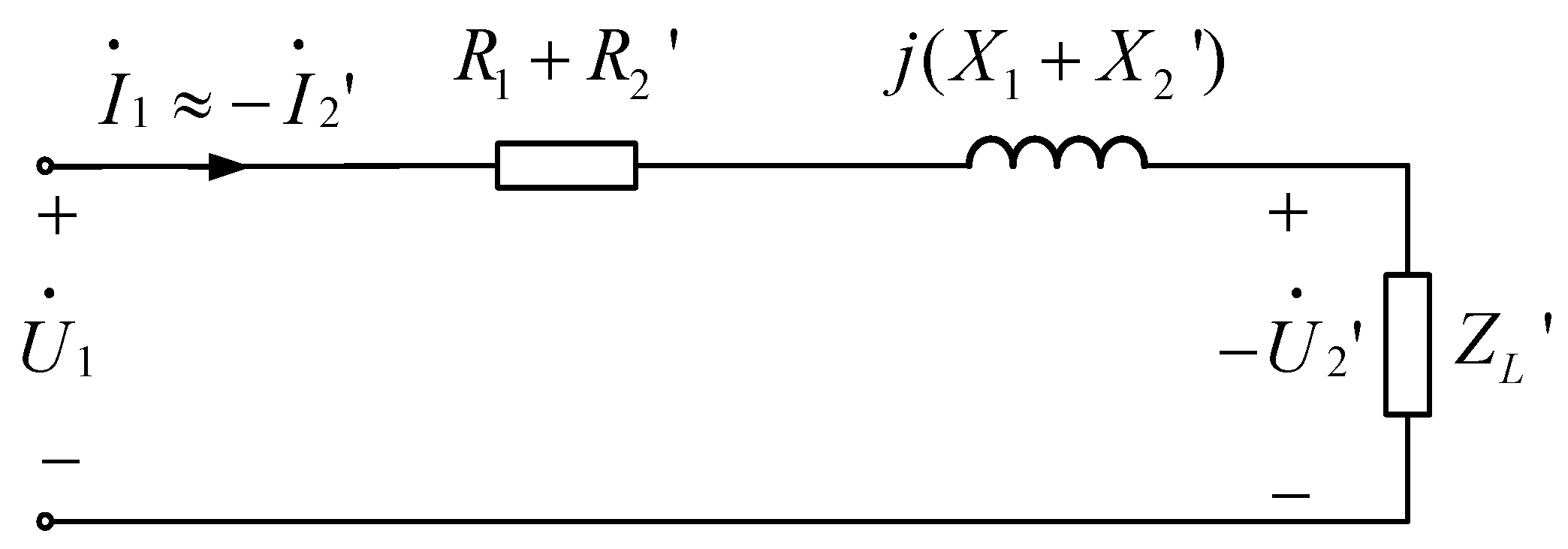
To investigate the mechanisms behind excessive short-circuit currents in substations, the positive-sequence equivalent circuit diagram of any 500 kV substation connected to any 220 kV substation is depicted in
Figure 2.
In
Figure 2,
represents the positive-sequence equivalent impedance of the 500 kV bus to ground, characterizing the transfer impedance associated with all 500 kV substations connected to this bus. The more 500 kV lines connected to it, the tighter the 500 kV network, resulting in a smaller value of
.
and
are the positive-sequence equivalent impedances of the transformer T configuration circuit.
denotes the positive-sequence equivalent impedance of the 220 kV bus to ground, which characterizes the transfer impedance associated with all 220 kV substations (including power plants) connected to this bus. The more 220 kV lines connected and the more power plants connected to the bus, the smaller this value becomes.
From
Figure 2, it can be noted that when a three-phase short circuit occurs on the 500 kV side, the self-impedance is given by
Let
be the voltage before the three-phase short circuit on the 500 kV side; then, the three-phase short-circuit current on the 500 kV side is
The self-impedance during a three-phase short circuit on the 220 kV side is
Let
be the voltage before the three-phase short circuit on the 220 kV side; then, the three-phase short-circuit current on the 220 kV side is
From Equations (2) and (4), it can be seen that to control the short-circuit current of the 500–220 kV electromagnetic ring network, it is necessary to start with increasing the impedance values of , , and . The commonly used technical measures for controlling short-circuit current in engineering are also based on the principle of increasing impedance.
Since the formats of Equations (2) and (4) are consistent, if we continue by making
, then the three-phase short-circuit current at this point
is
In this equation, represents the ground equivalent impedance of the bus under study for the short circuit. represents the ground equivalent impedance of the upstream or downstream bus connected to the short-circuit bus through the transformer.
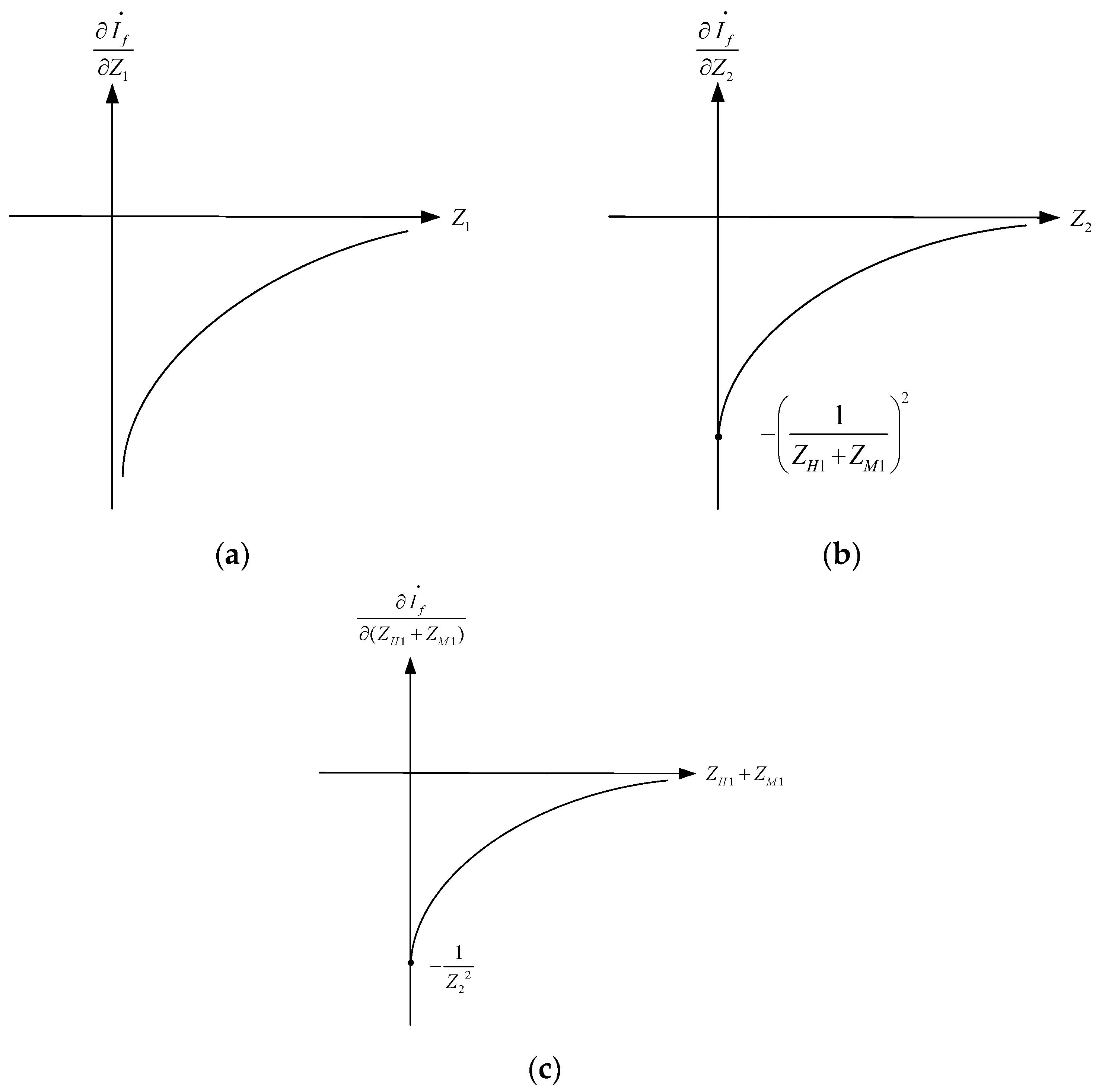
To investigate the degree of impact that impedance changes have on the short-circuit current, the short-circuit current from Equation (5) is taken as the function value, with the three impedances as independent variables. The partial derivatives are then calculated as
From Equation (6), it can be seen that the first-order partial derivatives of the short-circuit current with respect to the three impedances are all negative. This indicates that increasing the impedance will result in a decrease in the short-circuit current. To investigate the shape of the first-order partial derivative curves, let the second-order partial derivatives be
From Equation (7), it can be observed that the second-order partial derivatives are all positive, indicating that
,
, and
are all monotonically increasing functions over the interval
. The limits of the three first-order partial derivatives at the endpoints of the interval are calculated as
Based on the above derivation, the curves of the three-phase short-circuit current
with respect to the partial derivatives of the three components of impedance in the system can be plotted as shown in
Figure 3.
From
Figure 3, it can be seen that the values of the three partial derivatives are all negative within the defined domain. As the impedance decreases, the partial derivatives become smaller, indicating that the slope of the short-circuit current
becomes larger. This means that the short-circuit current
monotonically decreases as the three components of impedance increase. When the impedance increases arithmetically to limit the short-circuit current, the smaller the impedance value, the more significant the effect of increasing the impedance on limiting the short-circuit current; conversely, the larger the impedance value, the weaker the effect of further increasing the impedance to limit the short-circuit current.
Additionally, and both have limits at the zero point of impedance, which indicates that the control effect on the short-circuit current achieved by changing the non-same-level equivalent impedance and the transformer’s equivalent impedance is limited. Furthermore, the limit of at the zero point approaches negative infinity, indicating that the short-circuit current is most influenced by the same-level equivalent impedance to ground. Therefore, most current-limiting measures for short-circuit currents are based on increasing the same-level equivalent impedance at the short-circuit point.


