Abstract
Centrifugal compressors are widely used in different fields. Their design requires high performance and a wide operating range, where, at lower mass flow rates, unstable flow dynamic phenomena occur, which are extremely harmful and, at the same time, complex to fully understand. This review paper presents the main research from the last 40 years on the subject of instability in centrifugal compressors, aiming to clarify the main (sometimes contradictory) causes, classifying them according to the component in which they are triggered or the interaction between them. Importance is given to works that develop criteria for the identification of the stability limit with simplified models. The main techniques used to extend the stability limit are also presented by distinguishing between passive and active fixed-flow control methods; moreover, the main works on variable geometry techniques are reported, showing the advantages and disadvantages of their use. Finally, an overview of the innovative applications of centrifugal compressors, such as fuel cells, is presented. The aim of this review is to highlight the continued interest in this field of study and provide the tools to understand the different unstable mechanisms and techniques used to extend the operating limit.
1. Introduction
Compressors are a type of dynamic power-absorbing machinery wherein a fluid is elaborated continuously by rotating blades, in contrast to reciprocating machinery. In centrifugal compressors, the flow enters axially to become radial; this feature makes it more complex to build several stages in a cascade. In fact, they are mostly single-stage machines. Centrifugal compressors are widely used in various fields, such as in gas turbines (industrial, micro-gas turbine plants, aeronautics), the automotive sector for the supercharging of internal combustion engines, or the process industry (for process fluids, the supply of compressed air, cooling systems, etc.). Furthermore, even in recent fuel cell systems, the use of pressurized air allows for an increase in power density. Despite their small size compared to axial compressors, centrifugal compressors increase the tangential speed, which provides an additional work component; therefore, it is possible to achieve compression ratios between three and eight in a single stage, in contrast to the ratios of less than two obtained with an axial stage. However, centrifugal compressors possess a modest flow rate and have peripheral speeds that depend on the material used for the impeller blades; they range from approximately 200 m/s in the case of aluminum alloys to 500 m/s for titanium alloys. In addition, they possess high reliability and a good mass flow rate regulation margin because the performance of radial machines is less susceptible to the operating conditions than that of axial ones. A centrifugal compressor consists essentially of an impeller, a diffuser (which may be bladed), and a volute; the impeller can be unshrouded or shrouded, in the industrial case, to reduce leakage flows.
In recent decades, research on centrifugal compressors has considerably increased thanks to their ever-increasing use and the continuous demand for performance improvements; with regard to this, a comprehensive review of the application and development of this component was undertaken in 2005 by Krain [1]. In the same year, another review on its fluid dynamic phenomena was published by Senoo [2]. With the target of a lower environmental impact and a reduction in energy consumption, increasingly higher pressure ratios and efficiency are required. A further target design concerns an extended operating range due to the off-design operation in energy production plants but also in terrestrial propulsion. This is essentially limited by two distinct phenomena: choking at high mass flow rates and surging at low ones. The latter phenomenon induces strong fluctuations in the flow structure that can cause damage to the compressor and to the entire system; therefore, this condition must be avoided. Furthermore, it is close to the lowest mass flow rates for each rotational speed that the highest compression ratios and efficiency are obtained. Therefore, the study of the physical phenomena that led this type of compressor to unstable operation and towards a surge and the identification of strategies to extend the surge margin are relevant. Figure 1 shows the estimated number of research papers indexed in Scopus from the 1980s on the topic of surges and stability or techniques to extend the operating range for centrifugal compressors. As can be seen, an overall increase in the number of papers has been observed over the years, especially in the last decade.
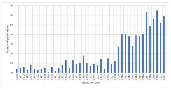
Figure 1.
Number of key publications on the stability, surge, and surge extension of centrifugal compressors. Resource: Scopus.
The aim of this review is to present the main works conducted in recent years primarily on the subject of surges and stability in centrifugal compressors. Attention is also paid to the description of the main works on the identification of criteria for the prediction of stable limits. Works on the techniques used to extend the operating range are presented, with a particular focus on casing treatment and variable geometry techniques in addition to studies on centrifugal compressors for more innovative applications, including fuel cells.
2. Stability
The stable operating limit in a centrifugal compressor is determined by the complex phenomenology in the flow, with an interaction between the machine components and the different sources of instability. The stability limit is located on the left part of the performance map, where, for each iso-speed, it is possible to identify the minimum mass flow rate before the occurrence of complex unstable flow mechanisms. In Figure 2, an example of a characteristic curve is provided, where it is highlighted that the maximum performance generally occurs near the stability limit, represented by the surge line. Over this limit, potentially dangerous mechanical problems can occur in the compressor, and the performance rapidly decreases.
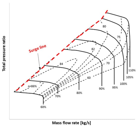
Figure 2.
Example of a characteristic curve of a centrifugal compressor, with the surge line highlighted.
Although surge and stall phenomena are intrinsically different, these terms are often commonly used to describe the same unstable phenomenon. In the case of decelerating flow, the fluid suffers an adverse pressure gradient. The kinetic energy contained within the boundary layer, being much lower than that of the main flow, can be overwhelmed by the adverse pressure gradient, leading to separation; locally, a flow recirculation zone can be generated. From a macroscopic point of view, this reorganization of the flow can be stationary (steady stall) or unsteady (rotating stall), where zones of separated flow and reattachments alternate and move in a circumferential direction. A stationary stall is generally accepted, as it does not create fluctuating loads on the impeller. A rotating stall is an unsteady phenomenon where the axisymmetric characteristic of the flow is replaced by zones of high and low kinetic energy that rotate at a sub-synchronous speed in the impeller. A surge is the flow condition wherein the entire compression system becomes unstable, resulting in violent changes in the inlet and outlet conditions, with typical low-frequency noise. It has a mass flow rate at a given cross-section that varies over time.
2.1. Unstable Flow Phenomena
In this section, the main works on the subject of instability in single-stage and two-stage centrifugal compressors are reported separately.
2.1.1. Single Stage
In this section, the main works concerning unstable phenomena, such as a rotating stall, are reported, starting with the first authors that conducted experiments. In the following, the main references are presented that highlight the complexity of the unstable phenomena related to different subcomponents and their interactions by distinguishing between cases with vaned and vaneless diffusers. Some works highlight the importance of the volute, which can induce instability in particular conditions. Then, the role of unsteady simulations on the study of these complex phenomena is explained and, finally, the most recent scientific works on these themes are detailed.
A rotating stall is one of the main precursors of a surge. A rotating stall can be generated by the destabilization of the flow in the impeller or diffuser or by an unsteady interaction between the different components. As an example, Figure 3 presents a static entropy contour in the diffuser–volute plane to highlight four rotating stall cells in a centrifugal compressor that rotates in the anti-clockwise direction.
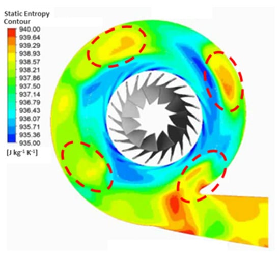
Figure 3.
Static entropy contours in diffuser–volute plane, with four rotating stall cells highlighted.
In 1984, Frigne and Van den Braembussche [3], through an experimental investigation, distinguished different types of rotating stalls thanks to an impeller that operated with different configurations of bladeless diffusers. Jansen [4] previously delved into the intricacies of the unsteady flow within a radial vaneless diffuser, offering a comprehensive examination of the emergence of self-excited oscillations characterized by significant amplitudes. The study meticulously investigated the conditions under which these waves materialize, emphasizing the critical role played by the angle between the tangential and total velocity, particularly when this angle diminishes significantly. In a subsequent exploration, Abdelhamid [5] conducted experiments to scrutinize the impact of the vaneless diffuser radius ratio on the occurrence of self-excited flow oscillations within a centrifugal compressor. This investigation provided valuable insights into the relationship between the diffuser geometry and the manifestation of flow oscillations. More recently, Iwakiri et al. [6] delved exclusively into impeller stall phenomena, employing both experimental and numerical methodologies with a detached Eddy simulation (DES) computational fluid dynamic (CFD) model. Their work shed light on the vortical structure, specifically a tornado-type separation vortex, triggered by full blade separation at the leading edge. This study contributed to a nuanced understanding of impeller stall mechanisms and the associated flow dynamics. Further advancements in the field were made by Tomita et al. [7], who conducted experimental and computational investigations on two compressors. Their work highlighted the significance of tip leakage vortex breakdown in impeller stall occurrences, demonstrating the intricate interplay between flow blockage and the breakdown of the tip leakage vortices. Collectively, these studies have expanded our understanding of unsteady flow phenomena, impeller stall mechanisms, and the role of diffuser geometry in influencing self-excited flow oscillations within centrifugal compressors.
Similar conditions of rotating stalls in vaned diffusers have been identified. Everitt and Spakovszky [8], with a URANS CFD model, showed that two types of stall precursors could be observed prior to full-scale instability: the development of long-wavelength modal waves or a short-wavelength, three-dimensional flow breakdown (so-called “spike” stall inception). Yoshida et al. [9,10] investigated the relationship between the impeller diffuser radial gap and the behavior of the vaned diffuser in rotating stall; a wider impeller diffuser radial gap was more likely to cause rotating stalls in the diffuser. Spakovszky [11] reported that backward traveling modal pre-stall waves occurred in the vaneless space prior to full-scale instability. Spakovszky and Roduner [12] demonstrated that the diffuser experienced both modal waves and spikes, with a small bleed flow in the vaneless space altering the diffuser’s matching and modifying the stall inception process in the diffuser. Previously, Krain [13] experimentally observed that impeller wakes could trigger unstable phenomena in a vaned diffuser. Liu et al. [14] confirmed, with a numerical work, the influence of the impeller on the vaned diffuser.
In the case of a vaneless diffuser, Yamada et al. [15], with a DES CFD approach, focused on the reverse flow phenomenon; they showed that the rotating cell in the diffuser was caused by the development of boundary layer separation and a reverse flow from the casing under deep surge conditions. PIV measures were implemented by Ohuchida et al. [16] to analyze the flow structure of the rotating stall phenomenon in the vaneless diffuser of a high-speed centrifugal compressor; the result obtained at the midspan indicated a typical pattern in the flow field, containing low- and high-velocity regions in a mutually circumferential direction. Dehner and Selamet [17] demonstrated that several small cells first initiated and formed a stall cell with the evolution of the reverse flow near the cutoff as the mass flow rate decreased. The merging of the low-velocity region released from the impeller into the diffuser stall cell was observed by Grapow et al. [18] using PIV measurements. Fujisawa et al. [19] recently analyzed the influence of the internal flow field within the impeller on the diffuser’s stall behavior.
The influence of the volute on the generation of instability mechanisms in the compressor has also been investigated. Jeon et al. [20] discussed the effect of volute matching as a possible cause of instability using a numerical approach. Ceyrowsky et al. [21] clarified the key role of the volute, mainly at high speeds. Yu et al. [22] investigated the impact on the compressor performance of various volute designs and diffuser modifications through steady simulations; the analysis was focused on both the diffuser and volute losses. Ayder and Van den Braembussche [23] described the volute behavior at off-design conditions; at higher-than-design mass flow rates, the volute cross-section was too small, thus acting as a nozzle, and the flow was accelerated in the circumferential direction. At a low mass flow rate, the volute cross-section was too large, diffusing the flow circumferentially. This variation affected the circumferential pressure distribution, which could affect the upstream components. Mishina and Gyobu [24] experimentally analyzed the impact of several volute design parameters, such as the cross-sectional shape, centerline radius, and cross-sectional area, on the global stage performance. Whitfield and Roberts [25] analyzed the combination of several volutes with a vaneless diffuser, stating that a volute with a cut-back tongue generated the lowest static pressure distortion. Hagelstein et al. [26] pointed out that the distortion amplitude increased towards the diffuser inlet.
The analysis of unsteady flows can support the understanding of the physical phenomena that trigger instability. Bousquet et al. [27] investigated the modifications of the flow structure when the operating point moved from peak efficiency to a near stall by demonstrating the intensification of secondary flow effects. Grondin et al. [28] performed an unsteady RANS simulation, showing rotating instabilities that occurred before the deep surge at high speeds due to separation at the impeller’s leading edge. Liskiewicz et al. [29] analyzed a low-speed centrifugal compressor, identifying near-surge inlet recirculation and a progressive impeller rotating stall. In Cao’s work [30], the unsteady tip leakage flow phenomenon was identified and investigated in a centrifugal compressor with a vaneless diffuser at near-stall conditions through numerical and experimental techniques. This study confirmed that the unstable flow was primarily driven by the Kelvin–Helmholtz instability inherent in the shear layer between the mainstream flow and the tip leakage flow. An unsteady simulation was conducted on the stall process under transonic inlet conditions. Yang et al. [31] analyzed the stall cell evolution pattern at the impeller inlet; the stall process could be divided into three stages: stall onset, stall development, and stall maturation. Fujisawa et al. [32] investigated the transient process of rotating stall development in a centrifugal compressor with a vaned diffuser. They identified two main aspects: the first was the process by which the vortex at the diffuser throat near the hub side developed in the circumferential direction, and the second was the mechanism of the diffuser stall’s expansion into the impeller passages. Bardelli et al. [33] investigated the impeller and vaned diffuser’s interaction for jet- and wake-flow patterns under different flow conditions. This interaction was indeed crucial, even at the point of best efficiency. In this context, Gaetani et al. [34] previously focused on the best efficiency point by highlighting the impact of the diffuser on the impeller concerning the static pressure and flow velocity; the interaction process introduced unsteadiness in the average flow rate discharged by an impeller channel and in the power exchange. Moreover, Boncinelli et al. [35] investigated two diffuser geometries in a Radiver centrifugal compressor to show the unsteadiness generated by the interaction between the diffusers and the impeller, already present at the best efficiency. In Table 1, a summary of the main works on the unstable phenomena in centrifugal compressors is provided, with the main causes and remarks discussed.

Table 1.
Studies on the unstable phenomena.
More recently, in 2022, Parikh et al. [36] studied the flow field of the inlet region of a centrifugal compressor under a steady and pulsating flow near a surge. Wolbert et al. [37] presented the results of a numerical investigation on the influence of the Reynolds number on the performance of a single-stage centrifugal compressor with an outward wound volute with a circular cross-section. Ni et al. [38] performed CFD simulations in a NASA centrifugal compressor to show the stall signal over seven impeller revolutions. Paul et al. [39] investigated the instability in a vaneless diffuser behind the trailing edge. Lou et al. [40] carried out experiments with fast-response transducers to identify stall inception under subsonic, transonic, and supersonic impeller tip conditions. In 2023, Zhang and Wu [41] showed the roles of the inducer and centrifuge in the evolution of impeller flow instability at a Mach number lower than one. Cao et al. [42] presented a detailed numerical investigation of a transonic centrifugal compressor, aiming to understand the mechanism causing its pressure rise characteristic rollover, which fundamentally affects a compressor’s stability. Suzuki et al. [43] investigated the unsteady pre-stall behavior of a centrifugal compressor with a vaned diffuser, identifying five disturbances in the circumferential direction that rotated at 1.7% of the rotational speed. The hysteresis effect of the volute on the compressor performance under pulsating conditions, focusing on the flow incidence variation at the tongue, was investigated by Hayashi et al. [44].
2.1.2. Two Stage
The unstable phenomena identified for a single-stage centrifugal compressor can represent the triggers in a tow-stage compressor; however, depending on its configuration (in-line or non-in-line), additional flow dynamic interactions can be responsible for additional flow phenomena. In Figure 4, a scheme representing the two configurations of a two-stage centrifugal compressor is provided.
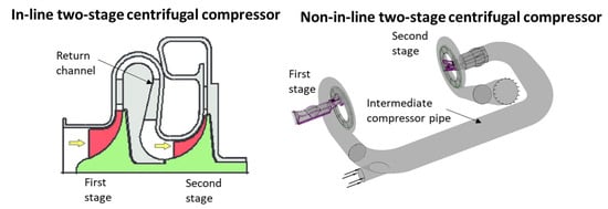
Figure 4.
Layout of two stage centrifugal compressor: (left) in-line and (right) non-in-line.
Two-stage centrifugal compressors are often used in the refrigeration field, where the refrigerant fluid arrives from a heat exchanger that brings it into the gaseous phase. These compressors make it possible to reach compression ratios higher than 14:1; however, due to the complexity involved in adding further components as well as the return channels between the two stages, in-depth knowledge of the fluid dynamic phenomena is also required in this case. Only the main works that have focused on this type of machine are discussed here. Palmer [45] found that reduced first-stage diffusion could improve the surge range over 80% rotational speeds, but the improvement was limited with inducer shroud bleed. It has been observed that, at low mass flow rates, the de-swirler vane influences the upstream flow structure of the vaneless diffuser and return channel [46]. Hung [47] suggested that, in the case of a vaned diffuser, the vane angle must be increased to reduce the surge mass flow rate. The IGV can have a beneficial effect if not combined with the previous parameter, but the width reduction of the second vaned diffuser can also be beneficial. Shen et al. [48] found that the distortion caused by the inlet pipe shape could affect the compressor’s stability and it could be controlled by an IGV. Xu [49] analyzed the interactions between the different components, concluding that the wake interaction only affected the downstream flow structure, while the potential flow interaction affected the upstream components; in fact, the diffuser was responsible for the influence of the impeller wakes. Zhu [50] showed that, at lower mass flow rates, the recirculation area for the vaneless diffuser was large, while the recirculation area at the vaned diffuser outlet was small; when decreasing the mass flow rate, a recirculation zone appeared at the impeller inlet. Halbe et al. [51] investigated the effect of a three-dimensional two-phase flow (including heat, mass, momentum transfer, and the droplet dynamics) in a two-stage centrifugal compressor. The same authors revealed that the liquid carryover altered the flow field within the compressor, causing both stages to operate at off-design conditions [52].
2.2. Surges in Compression System
A surge is an operating condition that affects the entire compression system, including the piping circuit. This phenomenon consists of a large periodic variation in the mass flow rate in the compressor and valve system that causes a periodic variation in the pressure in the plenum. The expansion system can be a valve or a turbine. A mild surge is a flow oscillation that covers 360° of the channels at a small amplitude, with no reverse flow each time. Meanwhile, a deep surge is achieved when there is a strong oscillation in the system. The latter phenomenon can cause severe damage to the machine; in fact, the violent flow variations repeatedly affect the rotating components, resulting in fatigue or even mechanical failure. In Figure 5, the signals of the mass flow rate for the two types of surge are presented.
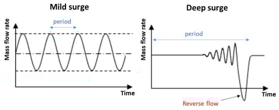
Figure 5.
The mass flow rate signal in mild surge (left) and deep surge (right) conditions.
First, the most well-known models of a surge are presented, followed by more recent works that have adopted a vibrational analysis for surge detection and, finally, the possible influence of heat transfer to it.
Emmons et al. [53] proposed several models, followed by Taylor [54] and Dussourd et al. [55]. The latter showed that, with adequate design, stable operation is possible down to 40 percent of the normal surge flow. Greitzer [56] extended the previous models to a nonlinear system. Simple dynamic parallel compressor models can support the understanding and improvement of compression system dynamics for centrifugal impellers [57]. As regards multistage centrifugal compressors, a dynamic surge control system was modeled and experimentally studied by Arnulfi et al. [58,59], who subsequently developed a passive control system using a nonlinear lumped model, which was then patented [60].
More recently, a vibrational analysis has been used to identify surge precursors [61,62,63]. Cabral et al. [64] proposed a specific method based on the fully acoustic two-port model for the study of centrifugal compressor stall and surge inception. In some cases, it was found that dynamic stalls related to flow instabilities generated a high level of sound and could also locally amplify incident sound waves. Marelli et al. [65] developed a specific flexible circuit installed downstream of the compressor to analyze the effect of the circuit geometry on a turbocharger compressor’s performance, with specific reference to the surge phenomenon. Ferrari et al. [66] presented experimental results obtained from a T100 microturbine connected with large volume sizes, with a specific reference to surge operations; a significant increase in vibrations was found near the unstable condition. The vibro-acoustic signal analysis showed a noteworthy increase in energy content in well-defined frequency bands, not only during surge events but also near the unstable condition [67,68]. In Dehner et al.’s work [68], high noise levels near the Helmholtz frequency were noted at low mass flow rates in the compressor, moving towards undesirable operating conditions. Aretakis et al. [69] highlighted an increase in low-frequency energy content below the fundamental order (sub-synchronous frequency content) in the acoustic response in the case of a turbocharger compressor. In Guillou et al.’s work [70], an experimental investigation of flow instability phenomena with reference to rotating stalls and surges was presented with reference to a turbocharger compressor with a ported shroud. The good capabilities of an ambient microphone to detect the onset of a vaneless diffuser rotating stall were presented by Romani et al. [71]; in particular, using a power spectrum analysis, they revealed that the relationship between the amplitude of the sub-synchronous region and that of the blade passing frequency, theorized in the case of dynamic pressure sensors through one dimensionless stall onset parameter, was still valid. The same techniques can be adopted for surge precursors; in fact, a rotating stall creates a rotating force that acts as a destabilizing external load on the rotor dynamics of the compressor [72,73].
Models of centrifugal compression systems have also integrated conjugate heat transfers as an important influencing factor in the study of unstable mechanisms. Geller et al. [74] presented an analytical equation to determine the heat transfer coefficient. Bohn et al. [75] developed various one-dimensional calculation specifications to describe the heat transfer phenomena. Baines et al. [76] proposed a one-dimensional heat transfer network model of a turbocharger that simulated the heat fluxes with good accuracy. Romagnoli and Martinez-Botas [77] developed a 1D heat transfer model, validated experimentally, which calculated the heat transferred through the turbocharger by means of the lump capacitance.
2.3. Stability Limit Criteria
One of the main areas of interest in the initial design phase of centrifugal compressors is to be able to predict the operating limits in order to then be able to regulate their operation in a safe and efficient manner; several criteria have been developed over the years.
The prediction of the choking condition appears to be well known; in this regard, a method for its prediction was already developed in the 1950s [78]. In contrast, the prediction of the surge condition is much more complex due to the presence of different phenomena. Greitzer [56] identified the dynamic stability limit of the stage with a peak in the performance curve (total pressure vs. mass flow); Japikse [79] extended the above criterion to the components and subcomponents of the stage. Subsequently, Hunziker [80] measured the pressure rise in the individual subcomponents of a vaned centrifugal compressor; he established that the stability limit was detected with a change in the slope of the pressure rise. For vaneless diffuser compressors, Senoo identified a critical flow angle value at the diffuser inlet as a criterion to detect the stability limit [81]. However, Clarke et al. [82] applied this criterion to a wide range of compressors, showing its limits. More recently, physics-based 1D compressor models have been proposed to predict the pressure ratio at the limit of stable operation [83]. The development of stability prediction criteria that can be applied with simplified CFD models without the need for an expensive, fully 3D, unsteady simulation of the centrifugal compressor stage is crucial to support the design process. Carretta et al. [84] developed a stability parameter based on the local slope of the performance map (static pressure vs. mass flow rate) to be applied with a CFD model of a single centrifugal compressor channel with a vaned diffuser. The same parameter applied to the various components and subcomponents made it possible to identify the weakest part that caused the entire machine to operate unstably. However, it was shown that this criterion was not accurate in the case of compressors with vaneless diffusers [85]. Cravero and Marsano [86,87] carried out an in-depth fluid dynamic analysis on a centrifugal compressor with a vaneless diffuser, showing that the phenomena that triggered the compressor’s stability were very different depending on the rotational speed. At low speeds, it has been observed that the flow separations, originating on the rotor suction side after the leading edge, interact with the tip leakage vortex and accumulate at the impeller exit. Meanwhile, at high rotational speeds, the volute plays a key role due to the increasing circumferential pressure gradient, reducing the mass flow that drives the diffuser into the stall cells, whose effect propagates back to the impeller inducer. Three different criteria related to low speeds with a single-channel 3D model have thus been developed: the critical flow angle and the recirculation zone for the diffuser and the diffusion ratio for the impeller. At higher speeds than the design condition, a criterion based on volute simulations and the related circumferential pressure gradient has been introduced. The same authors verified the effect of the volute on the triggering of unstable phenomena in a two-stage back-to-back radial compressor with a refrigerant gas [88]. Table 2 summarizes the different studies on the prediction of the stability limit of a centrifugal compressor.
Table 2.
Studies on prediction of stability limit.
3. Surge Extension Techniques
Contemporary objectives for automotive centrifugal compressors necessitate an extensive operating range or an enhancement in map width, especially at higher pressure ratios. This improvement is essential to facilitate higher boost pressure at low-end torque. To address emission reductions, enhance the specific fuel consumption, and refine the transient response, there is a need for efficiency improvements towards the surge line. Achieving a pressure ratio characteristic curve that consistently rises (exhibiting a negative gradient) towards a surge is vital in enhancing the boost pressure at lower rotational speeds, typically resulting in a more stable surge line. Different strategies to delay or postpone stalls and surges become necessary. There are two main approaches to increasing the operating range of a centrifugal compressor: passive and active flow control devices. In the former method, the compressor geometry is modified to induce changes in the flow structure, including the use of casing treatment techniques, e.g., grooves, slots, or even holes made in the compressor housing. The design of the grooves or slots was initially developed using experimental investigations [89]. However, their positions can be estimated using one-dimensional models. Generally, the grooves are concentrated in the impeller inducer region [90]; however, some authors have installed the devices directly next to the blade tip [91]. The active flow fixed devices instead act mainly on the compression system, aiming to actively suppress the oscillations that stem from the surge.
3.1. Passive Flow Control Methods
In contemporary automotive turbochargers, the adoption of the ported shroud solution is common, primarily owing to its cost-effectiveness and straightforward design. Originally proposed by Fisher in 1988 [92], this device features an axisymmetric cavity connecting a segment of the impeller with the induction duct. Typically designed with a U- or L-like shape, the ported shroud cavity serves as a notable element in modern turbocharger configurations. In Figure 6, the layout of a ported shroud with a sketch of its operating scheme near a surge is presented.
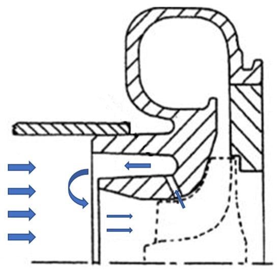
Figure 6.
Layout of ported shroud and its operation near surge.
The operational principle involves directing the low-momentum flow, prevalent in the inducer region under low mass flow rates, into a cavity for ingestion and recirculation. This recirculated flow is then reintroduced into an upstream section, where it blends with the primary flow. This process re-energizes the incoming stream to the rotor inducer, reducing the interference caused by the low-momentum flow, which would otherwise obstruct the inducer area. This strategy effectively shifts the surge condition to a lower mass flow. However, the performance may decline under conditions significantly different from the surge due to the effects of the cavity flow. Numerous scientific studies have focused on investigating and optimizing the ported shroud strategy. Researchers have confirmed that the advantages of this device, particularly in extending the surge margin, stem from the significant swirl generated in the same direction as the rotor by the recirculated flow at the impeller inducer [93]. Some researchers have proposed introducing a counter swirl by incorporating vanes into the cavity to control the recirculating flow. This can extend the surge margin without incurring excessive efficiency penalties [94]. Tamaki [95,96] achieved a notable surge margin improvement by installing a guide vane inside the recirculation cavity on a high-pressure turbocharger. Nikpour [97] focused on optimizing the ported shroud geometry, considering the slot positions, passage area, and cavity length. Xiao et al. [98] explored different slot positions and found that moving the cavity opening further upstream towards the impeller reduced the degradation in the compressor efficiency but diminished the surge margin extension due to the lower mass flow rate into the cavity. Sivagnanasundaram et al. [99] studied the impact of the cavity width on the impeller shroud, demonstrating that an increase in width extended the surge margin at the expense of the compressor stage efficiency. Kanzaka et al. [100] analyzed the number of struts and observed a more uniform axial velocity distribution along the span. The presence of compartments or real vanes inside the cavity or shroud has also been investigated. Barton et al. [101], through a simplified CFD model, verified the ability of the vane shroud to extend the compressor surge margin under the part-speed operating condition with acceptable high-speed performance; he found lower recirculation losses compared to a ported shroud. Sivagnanasundaram et al. [102] numerically investigated the map width enhancement and performance improvement of a turbocompressor using a series of static vanes in the annular cavity of a classical bleed slot system. The cavity vane removed some of the swirl, which could be carried through the bleed slot (influencing the pressure ratio); moreover, it provided better guidance to the slot, recirculating the flow before it mixed with the impeller’s main flow. Park et al. [103] simulated a ring groove casing treatment for flow range enhancement; the ring groove location and the effect of guide vanes in the ring groove was also investigated. Ma et al. [104,105] optimized a ring cavity to improve the operating stability by varying the shape of the ring; subsequently, inclined discrete cavities upstream of the impeller were proposed and optimized by increasing the stability by 5%. Ding et al. [106] experimentally investigated a holed casing treatment’s effects on the steady and transient characteristics, showing a surge margin improvement of up to 10%. Cravero et al. [107] performed a CFD experiment to quantify the extension of the surge margin improvement with the ported shroud through a stability criterion; the flow structure effects were also verified with an unsteady complete model. Intensive experimental campaigns to investigate the surge phenomena on a specific circuit with a ported shroud have also been performed [108,109]. Finally, the ported shroud has been analyzed to understand its acoustic characteristics near a surge [110] and at design conditions [111].
Among the passive methods involving the modification of the shroud, many more compact grooves have also been proposed, which can be arranged in different positions and orientations. Kurokawa et al. [112] fitted shallow grooves called J-Grooves with the aim of breaking the low-momentum vortex flow responsible for the rotating stall by forcing it to enter the cavities; however, this method, by reducing the tangential speed, reduced the efficiency of the compressor. More sophisticated configurations have been studied recently. Harley et al. [113] showed the potential of axial grooves to achieve similar results to a ported shroud but with a more packaged configuration; the axial groove helped to reduce the impeller passage’s reverse flow by maintaining the blade load, so that the inlet velocity triangle was modified. The system consisted of a single opening on the inducer shroud, where grooves were designed to guide the recirculating flow with the minimum losses. In Figure 7, the layout of a modern axial groove in an automotive centrifugal compressor is provided as an example.
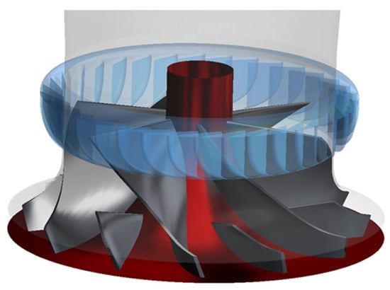
Figure 7.
Layout of modern axial groove in automotive centrifugal compressor.
Leichtfuß et al. [114] evaluated axial grooves in different compressor configurations, showing a surge extension, especially for high speeds; it reduced the inlet recirculation and increased the pressure ratio, while the efficiency decreased by 2% due to mixing losses. Cravero and Marsano [115] compared the advantages of the axial groove with those of the ported shroud. Configurations involving a circumferential groove casing treatment and an air bleeding circumferential groove casing treatment were analyzed on the KRAIN centrifugal compressor by Gao [116]. Finally, Chen et al. [117,118] analyzed a circumferential groove casing treatment in different vaned diffusers, showing a stable range extension of 9%; in fact, this device alleviated a blockage near the diffuser, the main cause of the rotating stall in the diffuser. Additional groove solutions have been derived from studies on axial compressor configurations [119,120,121].
Table 3 summarizes the main works on casing treatments for surge limit extension.
Table 3.
Studies on casing treatment techniques.
3.2. Active Flow Control Methods
The idea of extending the operating range of the compressor using active control techniques was first mentioned in the literature by Epstein et al. [122]; then, several experiments were conducted by Day [123], Paduano et al. [124], D’Andrea et al. [125], and Gysling and Greitzer [126]. The main contributions in this field were based on the works of Greitzer [127] and Moore and Greitzer [128], who proposed nonlinear models of the dynamics of the compression system; they have been extensively exploited in the analysis and design of control systems for the stabilization of the compression plant.
3.2.1. Actuators
Epstein [122] stated that surges can be prevented by actively suppressing the perturbations that cause the instability while their amplitude is low (local stabilization). On this basis, several experimental demonstrations of active surge stabilization have been published [129,130], and theoretical studies have also been performed to define the best control strategies [131,132]. In active surge control, the compressor has devices, such as a blowdown valve, that can be turned on or off. Generally, this type of method can be divided into two sub-classes: open loop and closed loop. In closed-loop control, a feedback law is used to activate the controller, while, in open-loop control, no feedback signals are used.
Active closed-loop control was first reported in 1989 [122]. The literature on this approach has expanded over the past decade. This method promises to be an integral aspect of future engines, so-called intelligent engines. Closed-loop controllers use a sensor to detect the growth of instability as the compressor experiences stall conditions. A feedback law relating the detected fluctuations to the blowdown rate is used to stabilize the compressor. Stall-detecting devices, which are generally found along the circumference of the compressor casing, activate a number of actuator devices, among which the air valve is the most commonly used actuator. Other types of actuators include variable-input guide vanes, recirculation, movable walls, and air injection.
3.2.2. Injection
Air injection, developed by Yeung and Murray [133], is another method of increasing the stall margin and has been used in both axial and centrifugal compressors. In this method, a small amount of high-velocity, high-pressure air is injected into the compressor. As a result, the flux is excited and the axial velocity component is increased; this reduces the flow angles and thus separation at the leading edge is prevented. Most of the active methods require complicated mechanisms and additional machinery, which ultimately reduces their overall efficiency and reliability. Therefore, it is still necessary to develop a simple method to suppress spinning stalls.
3.3. Variable Geometry Techniques
The main advantage of variable geometry techniques lies in extending the operating range without negatively affecting the performance of the compressor in the design condition. In fact, it is inactive at best efficiency conditions and gradually activated towards a surge. Variable geometries can be adopted both at the impeller inlet and in the diffuser.
The IGV consists of a blade array installed upstream of the impeller, which can generate a swirl with a positive or negative angle. In Figure 8, the speed triangles for the two cases with an IGV are shown. Xiao et al. [134] simulated the flow of a centrifugal compressor equipped with an IGV, verifying that the characteristic curves moved towards low mass flow rates in the case of a positive pre-swirl and towards higher mass flow rates in the case of a negative pre-swirl. They proposed improvements to minimize the pressure losses. Rodgers [135] studied the feasibility of adjusting the IGV in order to increase the stability limit of a centrifugal compressor with a vaneless diffuser; this can be implemented if the diffuser is in conditions far from instability. Subsequently, Rodgers [136] applied an IGV to a vaned diffuser compressor with success. It was observed that the IGV could create high losses for overly high adjustment angles at high mass flow rates and rotational speeds. In the automotive field, it has not yet found widespread use due to the production complexity or critical regulation in high regimes.
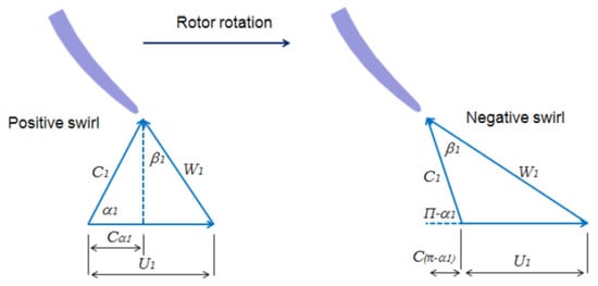
Figure 8.
Velocity triangles of IGV with different pre-swirl angles.
A variable IGV (VIGV) is used to increase the stall margin; its operating principle is to throttle the flow at the inlet, changing the density of the fluid and thus repositioning the operating point and changing the vortex input. A positive swirl brings the same flow angle relative to the inlet for a lower value of the axial speed; thus, the angle of attack for which a stall occurs is obtained for a lower range and more stable operation [137]. Uchida [138] studied a variable IGV in a turbocharger with a positive pre-swirl angle of up to 80°, showing an improvement in stability but a large pressure drop. Wallace et al. [139] performed a theoretical analysis of different pre-swirl distributions supported by an experimental campaign on a turbocharger. Najjar and Akeel [140] introduced the pre-swirl to alleviate the compressibility effect at the convex side of the eye so as to avoid the formation of shock waves and consequent losses. Ishino et al. [141] experimentally developed a VIGV for a small centrifugal compressor automotive, showing an advantage in terms of the efficiency and surge characteristics; in fact, it decreased the area of reverse flow at the shroud. Using LDA, Mohtar et al. [142] experimentally studied a VIGV in a centrifugal compressor, showing the advantage of VIGVs in extending the stable functioning of the compressor, associated with lower efficiency levels at moderate and high mass flow rates. Coppinger and Swain [143] demonstrated the significant enhancement that could be achieved in the stable operating range of an industrial centrifugal compressor through the strategic implementation of variable inlet guide vanes (IGVs). Their findings underscored the effectiveness of this approach in expanding the compressor’s operational envelope. Further investigations by Mohseni et al. [144] encompassed both experimental and numerical studies on a centrifugal compressor featuring three distinct types of IGVs. Their comprehensive results revealed that the utilization of tandem and S-cambered guide vanes led to superior aerodynamic performance and a broader operating range compared to symmetrical guide vanes. Interestingly, the tandem guide vane exhibited superiority under negative pre-swirl conditions, while the S-cambered guide vane excelled under positive pre-swirl conditions, highlighting the nuanced performance characteristics of different IGV configurations. Biela et al.’s [145] experimental exploration of a 1.5-stage compressor shed light on the impact of the IGV wake strength on the compressor’s stability. Additionally, their work emphasized the role of the IGV opening in influencing the tip leakage vortex structures, providing valuable insights into the intricacies of compressor dynamics. The numerical studies conducted by Xu et al. [49] on a two-stage centrifugal compressor with a variable inlet guide vane (VIGV) revealed a correlation between the evolution of the jet and wake downstream of the VIGV and the VIGV’s solidity. The study contributed to a deeper understanding of the fluid dynamics associated with VIGV configurations. Li et al. [146], employing a numerical model, achieved a noteworthy improvement of approximately 9.95% in the stall/surge margin through the implementation of a positive pre-swirl. Additionally, they employed advanced techniques, such as the modal decomposition method and flow field reconstruction, to investigate the coherent flow structures caused by low-frequency phenomena under different guide vane openings, providing valuable insights into the underlying flow dynamics. In 2023, Stemmermann et al. [147] delved into the instability phenomena of an industrial centrifugal compressor under various pre-swirl settings with a VIGV. Their study highlighted the substantial impact of this technique on the type of instability preceding the deep surge of the compressor stage, contributing valuable knowledge to the understanding of compressor behavior in dynamic operating conditions.
The variable geometry techniques used to control a surge can also be applied to the vaned diffuser of a centrifugal compressor. Jiao et al. [148] simulated the effects of variable diffuser vane angles on the compressor performance and operating range. The angle of the diffuser vane had a significant influence on the compressor’s operating range, and the optimized selection of the variable diffuser’s vane angle could increase the stable operating range and improve the compressor’s efficiency. Xue et al. [149] experimentally investigated a centrifugal compressor with a variable vaned diffuser, showing its behavior during surge changes at different diffuser vane angles. Justen et al. [150] experimentally studied a flat wedge vaned diffuser of a centrifugal compressor stage, achieving the independent, continuous adjustment of the diffuser vane angle and the radial gap between the impeller outlet and diffuser vane inlet. Simon et al. [151] implemented a vaned diffuser with a distinct angle in combination with variable inlet guide vanes to enhance both the operating range and efficiency of the compressor. Salvage [152] innovatively utilized a variable geometry split-ring pipe diffuser to ameliorate the surge margin of a compressor characterized by an excessive impeller–diffuser gap. Ziegler et al. [153] conducted an insightful study employing a vaned diffuser with an adjustable vane angle and radial gap between the diffuser vanes and the impeller. They explored the intricate interaction between the diffuser and impeller, adjusting the radial gap ratio within a range of 1.04 to 1.18. Their findings revealed that decreasing the radial gap led to an increase in the total pressure ratio of the compressor. In a recent study, Huang and Zheng [154] demonstrated the efficacy of the variable diffuser method in extending the stable operating range of a centrifugal compressor. By altering the diffuser vane angles by 10°, they expanded the stable operating range from 23.5% to 54.9% at a pressure ratio of 4.8. Ebrahimi et al. [155] delved into the mechanism behind the range extension of the variable diffuser through numerical investigations. Their results highlighted that adjusting the vane angle by +6° to −6° extended the operating range of the compressor by up to 30.0% for pressure ratios between 5.0 and 6.0.
In 2023, Tamaki and Yamaguchi [156] proposed a preliminary method for the design of a variable geometry vaned diffuser for a centrifugal compressor. This method aided in selecting the number of vanes for a variable vane diffuser (VVD) while also elucidating the relationship between the diffuser vane inlet angles and flow angles at the diffuser inlet during diffuser choking and stalling. Their proposal contributes to advancing the understanding and design considerations for variable geometry diffusers in centrifugal compressors.
Table 4 summarizes the main studies on variable geometry techniques for surge limit extension.
Table 4.
Studies on variable geometry techniques for surge limit extension.
4. Innovative Applications
The incorporation of centrifugal compressors in the automotive sector presents an opportunity to integrate them into fuel cells, aligning with the objective of achieving zero emissions, with heightened efficiency and a rapid response. Particularly in proton exchange membrane (PEM) fuel cells for automotive and aerospace applications, turbocharging is a prevalent practice. This is necessitated by the requirement for compressed air in the cathode system to enhance the overall fuel cell’s performance [157,158]. In the electrochemical reaction within a PEM fuel cell, hydrogen and oxygen combine to produce water as a byproduct. The cathode, where this reaction takes place, necessitates the integration of a compressor, an electric engine, and a turbine linked on the same shaft via the turbocharger. Typically, the utilization of a centrifugal compressor is favored over other types of machines due to its compact size, lightweight nature, swift response, prolonged lifespan, and superior efficiency. However, as highlighted by Venturi et al. [159], the turbocharger stands out as the most costly subsystem of the fuel cell cathode with the highest power demand. Additionally, an electric motor becomes essential since the radial turbine can only supply approximately one-third of the required power for the compressor. Consequently, optimizing the design of the centrifugal compressor becomes imperative, focusing on achieving the optimal performance in terms of the pressure ratio and efficiency. A crucial design objective is to expand the operating range, ensuring a sufficient stability margin across diverse operational conditions [160]. The schematic layout of a turbocharged fuel cell is depicted in Figure 9.
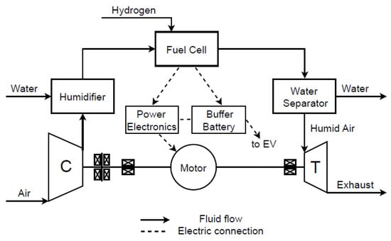
Figure 9.
Layout of turbocharged fuel cell.
Filsinger et al. [161] illustrated the capability of an electric turbocharger in a fuel cell system to ensure the required mass flow and regulate the pressure within the cathode gas path. Achieving a harmonious interaction among these components across a wide operating range necessitates the geometric optimization of individual components to encompass all specified operating points. On one hand, Schoedel et al. [162] conducted a study on performance map extension (PME) through the utilization of pivoting diffuser vanes and volute redesign. This initiative resulted in the substantial extension of the operating range, notably boosting the surge margin by up to 53.8%, albeit with a noteworthy efficiency penalty of up to 4.58%. On the other hand, aligning the turbine with the stack operating line while maximizing the efficiency is crucial. Consequently, Menze et al. [163] studied variable turbine geometries, specifically exploring the variable nozzle turbine and sliding nozzle turbine. The overarching objective of achieving optimal system performance requires the careful consideration of the interplay between the turbomachinery components, fuel cell stacks, and auxiliary devices. Nevertheless, an understanding of the intricate dynamics of turbomachines within the overall fuel cell system, coupled with a comprehensive evaluation of PMEs throughout the entire operating range and their impact on the performance, remains an unresolved challenge.
The compressor’s stability is crucial in fuel cell systems, especially when dealing with centrifugal compressors. Maintaining stable operation ensures efficient and reliable performance. In this context, Chen et al. [164] analyzed the unstable behavior of a compressor with the matching of the fuel cell. Hu et al. [165] underscored the pivotal role of compressors, powered by super high-speed permanent magnet synchronous motors, as a critical component within fuel cell systems; the operational stability of these compressors emerged as a key factor significantly influencing the overall performance of the fuel cells. Liu et al. [166] introduced an innovative online adaptive anti-surge control (OAASC) strategy tailored to proton exchange membrane (PEM) fuel cell systems. This strategy addresses a critical oversight in the air supply system, specifically the issue of a surge, which, if left unattended, poses the risk of damaging both the compressor and stack. Vu et al. [167] investigated the application of a multifunctional valve in a fuel cell system, positioned downstream of the compressor, to regulate the cathode air characteristics under varying loads and configurations; the study also addressed the delicate balance between surge protection and stack performance during transient conditions, presenting an optimal valve opening for throttle flow.
The system behavior of a fuel cell turbocharger was analyzed by Luck et al. [168] using a pseudo bond graph approach. A humidifier was added upstream of the fuel cell to control the humidity in the stack and thus the ion conductivity of the membrane. In addition, water separators were required to remove liquid water after the fuel cell and after the turbine [169,170]. In fact, the inflow from the fuel cell had a high humidity level. As the humid air expanded, the saturation line was crossed, subcooling occurred, and droplets formed. It was found that the condensation process significantly affected the performance map, power output, and efficiency of the turbine [171,172]. At the design operating point, the static temperature of the turbine outflow increased by up to 30K and the efficiency decreased by up to 2%. Besides some general considerations by Cunningham et al. [173] and more recently by Filsinger et al. [161], the authors are not aware of other work dealing with condensation and liquid water in a fuel cell turbocharger. However, condensation phenomena and the effects of liquid water in turbomachinery are well known from steam turbine research [174]. Whittmann [175] also considered the condensation phenomena by taking into account the circumferential symmetry of the volute, which is generally neglected. Additional insights into condensation within the radial turbine were derived from comprehensive CFD simulations utilizing the discrete phase model within commercial software. In the previous year, Wittmann et al. [176] provided an intricate description of the model, its validation, and a thorough exploration of the aerodynamic and thermodynamic phenomena associated with it. The resulting performance maps, crucial to understanding turbine behavior, were seamlessly integrated into the performance model presented in [177]. In contrast to conventional dry air simulations, addressing the release of latent heat during condensation requires an expanded set of performance map data. This extended dataset is vital in accurately representing the turbine’s performance under varied operating conditions. Specifically, the model incorporates considerations for condensation downstream of the turbine, recognizing that thermodynamic equilibrium may not be reached immediately. To achieve this, the model has been enriched by adopting the condensation approach proposed by Young [178], tailored to parallel ducts. This augmentation allows for a more nuanced and realistic representation of the complex interplay between condensation phenomena and turbine performance, contributing to a more comprehensive understanding of the system dynamics. Recently, the scope of information has been expanded by incorporating turbine performance maps that consider condensation, utilizing Euler–Lagrange CFD simulations [179]. In their work, the authors outlined a simulation methodology tailored to an electric turbocharger. This approach specifically accounts for the influence of moist air and the occurrence of condensation within the cathode gas supply system. The inclusion of these factors in the simulations contributed to a more comprehensive analysis of the electric turbocharger’s performance, offering valuable insights into its behavior under varying conditions related to moisture and condensation within the cathode gas supply system.
The centrifugal compressor can also be integrated into a solid oxide fuel cell (SOFC) thanks to its high temperature. Henke et al. [180] showed that the pressurization of SOFC systems leads to a significant increase in power density and electrical efficiency (an approximately 11% increase in both efficiencies from 1 to 5 bar). For the abovementioned reasons, turbocharged SOFC systems have begun to generate growing interest in the research community [181,182]. The turbocharger component, which is widely used in the automotive field, has a high level of technological maturity and a low cost when compared to a micro-gas turbine [183]. Mantelli et al. [184] have published preliminary work on the compressor instability’s effects on the off-design performance of a turbocharged SOFC system.
5. Conclusions
The presented review paper focuses on the instability of centrifugal compressors. The main research of the last 40 years is reported on, highlighting the multiple factors that trigger unstable operation. This issue is complex because different physical mechanisms based on different regimes or geometries are involved. In the literature, often contradictory statements are provided on the origin of the instability phenomena; for this reason, it is not easy to develop a unique theory. Therefore, in this review, the main instability mechanisms are described and classified according to the components in which they occur or the interactions between them, bringing together contradictory statements among different works. With both experimental and numerical analyses, the phenomena that drive the compressor towards unstable operation are identified; they include rotating stall phenomena that induce large oscillations, reverse flows, blockages due to tip leakage vortex breakdown, and wake impeller–diffuser interactions but also the highly asymmetric flow of the volute, the pressure distortion generated by the tongue, and other complex phenomena. Works on this theme for single- or two-stage compressors are distinguished. An important focus is given to works that have developed criteria for the identification of the stability limit in the various families of centrifugal compressors. Some authors have developed a stability parameter based on the local slope of the performance map to be applied with a CFD model of a single centrifugal compressor channel with a vaned diffuser. For compressors with vaneless diffusers, different criteria have been developed: at low rotation speeds, based on flow separations originating on the rotor suction side after the leading edge, they interact with the tip leakage vortex and accumulate at the impeller exit; at high speeds, a criterion based on the circumferential pressure gradient induced by the volute propagating upstream has been developed. Furthermore, the often-abused concept of surges, reserved for compression systems with a given circuit, is clarified, describing the main models present in the literature for its analysis.
The extension of the operating range is an important target for the designer in order to ensure the adaptability of the compressor during regulation and to achieve a larger surge margin for improved performance. In this review, the main techniques used to extend the stable operating limit are presented through fixed geometry techniques with passive flow control methods (such as casing treatment) and active flow control methods; numerous works on variable geometry techniques are also presented. The main advantages and disadvantages in their use are presented. It is observed that cavities, mounted on the shroud, are used with the aim of forcing the low-momentum flow in the inducer region at a low mass flow rate to be ingested and recirculated into the cavity (such as a ported shroud or axial or circumferential grooves). Among the active flow control techniques, models have been developed that actively suppress the perturbations that lead to instability through regulation systems (such as valves or air injection). Furthermore, variable geometry techniques are widely used, such as the VIGV (upstream of the impeller) or the VVD at the diffuser, with the aim of improving the operating range without negatively affecting the performance of the compressor in the design condition.
Despite the new trends and rules regarding internal combustion engines, the interest in the development of centrifugal compressors for the automotive sector remains highly strategic thanks to innovative applications, including fuel cells, where, at the cathode, the installation of the compressor is often required in order to increase the fuel cell’s performance. The appropriate matching of the fuel cell and the compressor is still challenging in terms of ensuring a wide operating range and avoiding compressor instability.
This review aims to shed light on the mechanisms of instability generation by distinguishing the different possible sources, presenting the main techniques used to delay the triggering of such phenomena and illustrating the continuous interest in the development of centrifugal compressors and in the previous topics. Furthermore, it provides a basis for modern engineering to select the correct tools for monitoring and predictive maintenance through the use of the recent machine learning methods, ensuring optimal performance, efficiency, and reliability.
Author Contributions
C.C. and D.M. equally contributed to the conception of the research activity, the setup of the model, the discussion of the results, and the writing of the paper. All authors have read and agreed to the published version of the manuscript.
Funding
This study received no external funding.
Institutional Review Board Statement
Not applicable.
Informed Consent Statement
Not applicable.
Data Availability Statement
Not applicable.
Conflicts of Interest
The authors declare no conflicts of interest.
References
- Krain, H. Review of centrifugal compressor’s application and development. J. Turbomach. 2005, 127, 25–34. [Google Scholar] [CrossRef]
- Senoo, Y. Researches on fluid dynamics of centrifugal compressors. Proc. Jpn. Acad. Ser. B 2005, 81, 77–85. [Google Scholar] [CrossRef][Green Version]
- Frigne, P.; Van Den Braembussche, R. Distinction between different types of impeller and diffuser rotating stall in a centrifugal compressor with vaneless diffuser. J. Eng. Gas Turbines Power 1984, 106, 468–474. [Google Scholar] [CrossRef]
- Jansens, W. Rotating stall in a vaneless diffuser. ASME J. Basic Eng. 1964, 86, 750–758. [Google Scholar] [CrossRef]
- Abdelhamid, A.N. Effects of vaneless diffuser geometry on flow instability in centrifugal compression systems. Can. Aeronaut. Space J. 1983, 3, 259–266. [Google Scholar]
- Iwakiri, K.; Furukawa, M.; Ibaraki, S.; Tomita, I. Unsteady and three-dimensional flow phenomena in a transonic centrifugal compressor impeller at rotating stall. Turbo Expo Power Land Sea Air 2009, 48883, 1611–1622. [Google Scholar]
- Tomita, I.; Ibaraki, S.; Furukawa, M.; Yamada, K. The effect of tip leakage vortex for operating range enhancement of centrifugal compressor. J. Turbomach. 2013, 135, 051020. [Google Scholar] [CrossRef]
- Everitt, J.N.; Spakovszky, Z.S. An investigation of stall inception in Centrifugal compressor vaned diffuser. ASME J. Turbomach. 2013, 135, 011025. [Google Scholar] [CrossRef]
- Yoshida, Y.; Tsurusaki, H.; Murakami, Y.; Tsujimoto, Y. Rotating stalls in centrifugal impeller/vaned diffuser systems (1st Report). Trans. JSME 1990, 56, 2991–2998. [Google Scholar] [CrossRef]
- Yoshida, Y.; Tsurusaki, H.; Murakami, Y.; Tsujimoto, Y. Rotating stalls in centrifugal impeller/vaned diffuser systems (2nd Report). Trans. JSME 1990, 56, 2999–3006. [Google Scholar] [CrossRef]
- Spakovszky, Z.S. Backward Travelling Rotating Stall Waves in Centrifugal Compressors. ASME J. Turbomach. 2004, 126, 1–12. [Google Scholar] [CrossRef]
- Spakovszky, Z.S.; Roduner, C.H. Spike and Modal Stall Inception in an Advanced Centrifugal Compressor. ASME J. Turbomach. 2009, 131, 031012. [Google Scholar] [CrossRef]
- Krain, H. A study on centrifugal impeller and diffuser flow. J. Eng. Power 1981, 103, 688–697. [Google Scholar] [CrossRef]
- Liu, Y.; Liu, B.; Lu, L. Investigation of unsteady impeller-diffuser interaction in a transonic centrifugal compressor stage. Turbo Expo Power Land Sea Air 2010, 44021, 1961–1971. [Google Scholar]
- Yamada, K.; Furukawa, M.; Arai, H.; Kanzaki, D. Evolution of reverse flow in a transonic centrifugal compressor at near-surge. Turbo Expo Power Land Sea Air 2017, 50800, V02CT44A014. [Google Scholar]
- Ohuchida, S.; Kawakubo, T.; Tamaki, H. Experimental study of rotating stall in vaneless diffuser of a centrifugal compressor. Turbo Expo Power Land Sea Air 2013, 55249, V06CT40A014. [Google Scholar]
- Dehner, R.; Selamet, A. Three-Dimensional Computational Fluid Dynamics Prediction of Turbocharger Centrifugal Compression System Instabilities. ASME J. Turbomach. 2019, 141, 081004. [Google Scholar] [CrossRef]
- Grapow, F.; Olasek, K.; Liskiewicz, G.; Nagiera, R.; Kryllowicz, W. Experimental Study of Vaneless Diffuser Rotating Stall Development and Cell-Merging Phenomena. ASME J. Turbomach. 2021, 143, 051008. [Google Scholar] [CrossRef]
- Fujisawa, N.; Naitou, M.; Ohta, Y. Interaction mechanism of impeller and diffuser stall in a centrifugal compressor. In Proceedings of the ASME Turbo Expo 2022: Turbomachinery Technical Conference and Exposition, Rotterdam, The Netherlands, 13–17 June 2022. ASME Paper GT2022-82861. [Google Scholar]
- Jeon, S.H.; Hwang, D.H.; Park, J.H.; Kim, C.H.; Baek, J.H.; Kim, H.W. Numerically Study on the Effect of a Volute on Surge Phenomena in a Centrifugal Compressor. In Proceedings of the ASME Turbo Expo 2016: Turbomachinery Technical Conference and Exposition, Seoul, Republic of Korea, 13–17 June 2016. ASME Paper GT2016-57542. [Google Scholar]
- Ceyrowsky, T.; Hildebrandt, A.; Schwarze, R. Numerical investigation of the circumferential pressure distortion induced by a centrifugal compressor’s external volute. In Proceedings of the ASME Turbo Expo 2018: Turbomachinery Technical Conference and Exposition, Oslo, Norway, 11–15 June 2018. ASME Paper GT2018-75919. [Google Scholar]
- Yu, L.; Cousins, W.T.; Shen, F.; Kalitzin, G.; Sishtla, V.; Sharma, O. Numerical Investigation of the Effect of Diffuser and Volute Design Parameters on the Performance of a Centrifugal Compressor Stage. Turbo Expo Power Land Sea Air 2016, 49729, V02DT42A024. [Google Scholar]
- Ayder, E.; Van den Braembussche, R.A. Experimental and Theoretical Analysis of the Flow in a Centrifugal Compressor Volute. ASME J. Turbomach. 1993, 115, 582–589. [Google Scholar] [CrossRef]
- Mishina, H.; Gyobu, I. Performance Investigations of Large Capacity Centrifugal Compressors. In Proceedings of the ASME 1978 International Gas Turbine Conference and Products Show, London, UK, 9–13 April 1978. [Google Scholar]
- Whitfield, A.; Roberts, D.V. Alternative vaneless diffusers and collecting volutes. In Proceedings of the ASME 28th International Gas Turbine Conference, Phoenix, AZ, USA, 27–31 March 1983. Paper 83-GT-32. [Google Scholar]
- Hagelstein, D.; Van den Braembussche, R.A.; Keiper, R.; Rautenberg, M. Experimental investigation of the circumferential static pressure distortion in centrifugal compressor stages. In Proceedings of the ASME 1997 International Gas Turbine and Aeroengine Congress and Exhibition, Orlando, FL, USA, 2–5 June 1997. Paper 97-GT-050. [Google Scholar]
- Bousquet, Y.; Carbonneau, X.; Dufour, G.; Binder, N.; Trebinjac, I. Analysis of the unsteady flow field in a centrifugal compressor from peak efficiency to near stall with full-annulus simulations. Int. J. Rotating Mach. 2014, 729629. [Google Scholar] [CrossRef]
- Grondin, J.; Trébinjac, I.; Rochuon, N. Rotating instabilities versus rotating stall in a high-speed centrifugal compressor. Turbo Expo Power Land Sea Air 2018, 51005, V02BT44A025. [Google Scholar]
- Liśkiewicz, G.; Sobczak, K.; Stickland, M.; Kryłłowicz, W. Numerical study of off-design centrifugal compressor operation and flow phenomena preceding surge. Turbo Expo Power Land Sea Air 2018, 50992, V02AT45A035. [Google Scholar]
- Cao, T.; Kanzaka, T.; Xu, L.; Brandvik, T. Tip Leakage Flow Instability in a Centrifugal Compressor. Turbo Expo Power Land Sea Air 2019, 58561, V02BT44A003. [Google Scholar]
- Yang, C.; Wang, W.; Zhang, H.; Li, Y.; Tong, D.; Yang, C.; Yi, W. Investigation of stall process in a centrifugal compressor with a volute under transonic conditions. Turbo Expo Power Land Sea Air 2019, 58554, V02AT45A006. [Google Scholar]
- Fujisawa, N.; Takahashi, M.; Ohta, Y. Transient Analysis of Rotating Stall Development in a Centrifugal Compressor with Vaned Diffuser. Turbo Expo Power Land Sea Air 2019, 58554, V02AT45A010. [Google Scholar]
- Bardelli, M.; Cravero, C.; Marini, M.; Marsano, D.; Milingi, O. Numerical Investigation of Impeller-Vaned Diffuser Interaction in a Centrifugal Compressor. Appl. Sci. 2019, 9, 1619. [Google Scholar] [CrossRef]
- Gaetani, P.; Persico, G.; Mora, A.; Dossena, V.; Osnaghi, C. Impeller–Vaned Diffuser Interaction in a Centrifugal Compressor at the Best Efficiency Point. Proc. ASME Turbo Expo 2011, 7, 2087–2097. [Google Scholar]
- Boncinelli, P.; Ermini, M.; Bartolacci, S.; Arnone, A. Impeller-diffuser interaction in centrifugal compressors: Numerical analysis of Radiver test case. J. Propuls. Power 2007, 23, 1304–1312. [Google Scholar] [CrossRef]
- Parikh, A.; Ale-Martos, P.; Barrera-Medrano, M.E.; Hayashi, Y.; Martinez-Botas, R. Computational Flow Field Assessment of the Inlet Region of Centrifugal Compressor Under Unsteady Flow Conditions Near Surge. Turbo Expo Power Land Sea Air 2022, 86106, V10BT35A005. [Google Scholar]
- Wolbert, D.; Schmitt, M.; Koenig, S.; Wannek, M.; Hartmann, J. A Numerical Investigation on the Influence of Reynolds Number on the Performance of Volute Stages of Centrifugal Compressors. Turbo Expo Power Land Sea Air 2022, 86106, V10BT35A012. [Google Scholar]
- Ni, M.; Robles Vega, G.; Ni, R.H.; Clark, J.; List, M. Numerical Observations of a Stall Phenomenon in the NASA CC3 Compressor. Turbo Expo Power Land Sea Air 2022, 86113, V10CT32A004. [Google Scholar]
- Paul, D.; Eißler, W. Numerical Investigation of Unsteady Flow Phenomena in a Centrifugal Compressor Operating Near Surge with a Geometrically Reduced Model. Turbo Expo Power Land Sea Air 2022, 86120, V10DT37A008. [Google Scholar]
- Lou, F.; Harrison, H.M.; Brown, W.J.; Key, N.L. Investigation of Surge in a Transonic Centrifugal Compressor with Vaned Diffuser: Part II—Correlation with Subcomponent Characteristics. J. Turbomach. 2023, 145, 051004. [Google Scholar] [CrossRef]
- Zhang, M.; Wu, W. Role of the inducer in flow instability of a high-speed centrifugal compressor impeller. In Proceedings of the ASME Turbo Expo 2023: Turbomachinery Technical Conference and Exposition, Boston, MA, USA, 26–30 June 2023. Paper GT2023-103035. [Google Scholar]
- Cao, T.; Hayashi, Y.; Tomita, I. Pressure characteristic rollover of a transonic centrifugal impeller. In Proceedings of the ASME Turbo Expo 2023: Turbomachinery Technical Conference and Exposition, Boston, MA, USA, 26–30 June 2023. Paper GT2023-101815. [Google Scholar]
- Suzuki, Y.; Fujisawa, N.; Ohta, Y. Unsteady pre-stall behavior in a centrifugal compressor with vaned diffuser. In Proceedings of the ASME Turbo Expo 2023: Turbomachinery Technical Conference and Exposition, Boston, MA, USA, 26–30 June 2023. Paper GT2023-102425. [Google Scholar]
- Hayashi, Y.; Parikh, A.; Barrera-Medrano, M.E.; Martinez-Botas, R. Hysteresis effect of volute on compressor performance under pulsating flow condition. In Proceedings of the ASME Turbo Expo 2023: Turbomachinery Technical Conference and Exposition, Boston, MA, USA, 26–30 June 2023. Paper GT2023-102332. [Google Scholar]
- Palmer, D.L.; Waterman, W.F. Design and Development of an Advanced two-stage Centrifugal Compressor. Turbo Expo Power Land Sea Air 1994, 78842, V002T02A006. [Google Scholar]
- Huang, J.M.; Tsai, Y.H. Design and analysis of a split deswirl vane in a two-stage refrigeration centrifugal compressor. Adv. Mech. Eng. 2014, 6, 130925. [Google Scholar] [CrossRef]
- Hung, K.S.; Chung, J.C.; Liu, C.C.; Huang, J.M. A study of off-design performance improvement for a centrifugal refrigerant compressor. Adv. Mech. Eng. 2017, 9, 1687814017696224. [Google Scholar] [CrossRef]
- Shen, F.; Yu, L.; Cousins, W.T.; Sishtla, V.; Sharma, O.P. Numerical investigation of the flow distortion impact on a refrigeration centrifugal compressor. Turbo Expo Power Land Sea Air 2016, 49729, V02DT42A025. [Google Scholar]
- Xu, C.; Fan, C.; Zhang, Z.; Mao, Y. Numerical study of wake and potential interactions in a two-stage centrifugal refrigeration compressor. Eng. Appl. Comput. Fluid Mech. 2021, 15, 313–327. [Google Scholar] [CrossRef]
- Zhu, W.; Ren, X.D.; Li, X.S.; Gu, C.W. Analysis and improvement of a two-stage centrifugal compressor used in an MW-level gas turbine. Appl. Sci. 2018, 8, 1347. [Google Scholar] [CrossRef]
- Halbe, C.V.; O’Brien, W.F.; Cousins, W.T.; Sishtla, V. A CFD analysis of the effects of two-phase flow in a two-stage centrifugal compressor. Turbo Expo Power Land Sea Air 2015, 56659, V02CT42A016. [Google Scholar]
- Halbe, C.V.; O’Brien, W.F.; Cousins, W.T.; Sishtla, V. A numerical analysis of the effects of liquid carryover on the performance of a two-stage centrifugal compressor. Turbo Expo Power Land Sea Air 2018, 51005, V02BT44A028. [Google Scholar]
- Emmons, H.W.; Pearson, C.E.; Grant, H.P. Compressor surge and stall propagation. Trans. Am. Soc. Mech. Eng. 1955, 77, 455–467. [Google Scholar] [CrossRef]
- Taylor, E.S. The Centrifugal Compressor: Aerodynamics of Turbines and Compressors. In High Speed Aerodynamics and Jet Propulsion; 1960; Volume 10. [Google Scholar]
- Dussourd, J.L.; Pfannebecker, G.W.; Singhania, S.K. An experimental investigation of the control of surge in radial compressors using close coupled resistances. J. Fluids Eng. 1977, 99, 64–74. [Google Scholar] [CrossRef]
- Greitzer, E.M. The stability of pumping systems. The 1980 Freeman Scholar lecture. Trans. ASME J. Fluids Eng. 1981, 103, 193–242. [Google Scholar] [CrossRef]
- Cousins, W.T.; Davis, M.W., Jr. The Influence of the Characteristics of a Centrifugal Compressor on System Stability and Distortion Response. Turbo Expo Power Land Sea Air 2012, 44670, 37–49. [Google Scholar]
- Arnulfi, G.L.; Giannattasio, P.; Giusto, C.; Massardo, A.F.; Micheli, D.; Pinamonti, P. Multistage centrifugal compressor surge analysis: Part I—Experimental investigation. J. Turbomach. 1999, 121, 305–311. [Google Scholar] [CrossRef]
- Arnulfi, G.L.; Giannattasio, P.; Giusto, C.; Massardo, A.F.; Micheli, D.; Pinamonti, P. Multistage centrifugal compressor surge analysis: Part II—Numerical simulation and dynamic control parameters evaluation. J. Turbomach. 1999, 121, 312–320. [Google Scholar] [CrossRef]
- Arnulfi, G.L.; Giannattasio, P.; Micheli, D.; Pinamonti, P. An innovative device for passive control of surge in industrial compression systems. J. Turbomach. 2001, 123, 473–482. [Google Scholar] [CrossRef]
- Silvestri, P.; Marelli, S.; Capobianco, M. Incipient Surge Analysis in Time and Frequency Domain for Centrifugal Compressors. J. Eng. Gas Turbines Power 2021, 143, 101020. [Google Scholar] [CrossRef]
- Champ, C.A.N.M.D.H.; Silvestri, P.; Ferrari, M.L.; Massardo, A.F. Incipient Surge Detection in Large Volume Energy Systems Based on Wigner–Ville Distribution Evaluated on Vibration Signals. J. Eng. Gas Turbines Power 2021, 143, 071014. [Google Scholar] [CrossRef]
- Reggio, F.; Silvestri, P.; Ferrari, M.L.; Massardo, A.F. Operation extension in gas turbine-based advanced cycles with a surge prevention tool. Meccanica 2022, 57, 2117–2130. [Google Scholar] [CrossRef]
- Kabral, R.; Åbom, M. Investigation of turbocharger compressor surge inception by means of an acoustic two-port model. J. Sound Vib. 2018, 412, 270–286. [Google Scholar] [CrossRef]
- Marelli, S.; Misley, A.; Silviestri, P.; Capobianco, M.; Taylor, A.; Canova, M. Experimental Investigation on Surge Phenomena in an Automotive Turbocharger Compressor; SAE Technical Paper; SAE International: Warrendale, PA, USA, 2018. [Google Scholar] [CrossRef]
- Ferrari, M.L.; Silvestri, P.; Pascenti, M.; Reggio, F.; Massardo, A.F. Experimental dynamic analysis on a T100 microturbine connected with different volume sizes. J. Eng. Gas Turbines Power 2018, 140, 021701. [Google Scholar] [CrossRef]
- Sun, Z.; Zou, W.; Zheng, X. Instability detection of centrifugal compressors by means of acoustic measurements. Aerosp. Sci. Technol. 2018, 82, 628–635. [Google Scholar] [CrossRef]
- Dehner, R.; Figurella, N.; Selamet, A.; Keller, P.; Becker, M.; Tallio, K.; Miazgowicz, K.; Wade, R. Instabilities at the low-flow range of a turbocharger compressor. SAE Int. J. Engines 2013, 6, 1356–1367. [Google Scholar] [CrossRef]
- Aretakis, N.; Mathioudakis, K.; Kefalakis, M.; Papailiou, K. Turbocharger unstable operation diagnosis using vibroacoustic measurements. J. Eng. Gas Turbines Power 2004, 126, 840–847. [Google Scholar] [CrossRef]
- Guillou, E.; Gancedo, M.; Gutmark, E. Experimental investigation of flow instability in a turbocharger ported shroud compressor. J. Turbomach. 2016, 138, 061002. [Google Scholar] [CrossRef]
- Romani, L.; Bosi, L.; Baroni, A.; Toni, L.; Biliotti, D.; Ferrara, G.; Bianchini, A. Detection of vaneless diffuser rotating stall by means of dynamic pressure sensors and acoustic measurements. E3S Web Conf. 2021, 312, 11007. [Google Scholar]
- Bianchini, A.; Biliotti, D.; Ferrara, G.; Ferrari, L.; Belardini, E.; Giachi, M.; Tapinassi, L.; Vannini, G. A systematic approach to estimate the impact of the aerodynamic force induced by rotating stall in a vaneless diffuser on the rotordynamic behavior of centrifugal compressors. J. Eng. Gas Turbines Power 2013, 135, 112502. [Google Scholar] [CrossRef]
- Biliotti, D.; Bianchini, A.; Vannini, G.; Belardini, E.; Giachi, M.; Tapinassi, L.; Ferrari, L.; Ferrara, G. Analysis of the rotordynamic response of a centrifugal compressor subject to aerodynamic loads due to rotating stall. J. Turbomach. 2015, 137, 021002. [Google Scholar] [CrossRef]
- Geller, I.M.; Kluck, D.I.N.; Magiera, D.I.R. Numerical computation of heat transfer coefficient for a radial compressor stage using CFD and comparison with analytical model computations. In Proceedings of the 24th CADFEM Users’ Meeting, Schwabenlandhalle Stuttgart/Fellbach, Germany, 25–27 October 2006. [Google Scholar]
- Bohn, D.; Heuer, T.; Kusterer, K. Conjugate flow and heat transfer investigation of a turbo charger. J. Eng. Gas Turbines Power 2005, 127, 663–669. [Google Scholar] [CrossRef]
- Baines, N.; Wygant, K.D.; Dris, A. The analysis of heat transfer in automotive turbochargers. J. Eng. Gas Turbines Power 2010, 132, 042301. [Google Scholar] [CrossRef]
- Romagnoli, A.; Martinez-Botas, R. Heat transfer analysis in a turbocharger turbine: An experimental and computational evaluation. Appl. Therm. Eng. 2012, 38, 58–77. [Google Scholar] [CrossRef]
- Lown, H.; Wiesner, F.J., Jr. Prediction of choking flow in centrifugal impellers. J. Basic Eng. 1959, 81, 29–35. [Google Scholar] [CrossRef]
- Japikse, D. A critical evaluation of stall concepts for centrifugal compressors and pumps–studies in component performance. Part 7. In Stability, Stall and Surge in Compressors and Pumps; 1984; pp. 1–10. [Google Scholar]
- Hunziker, R.; Gyarmathy, G. The operational stability of a centrifugal compressor and its dependence on the characteristics of the subcomponents. J. Turbomach. 1994, 116, 250–259. [Google Scholar] [CrossRef]
- Senoo, Y.; Kinoshita, Y. Influence of inlet flow conditions and geometries of centrifugal vaneless diffusers on critical flow angle for reverse flow. ASME J. Fluids Eng. 1977, 99, 98–102. [Google Scholar] [CrossRef]
- Clarke, C.; Marechale, R.; Engeda, A.; Cave, M. Investigation of centrifugal compressor vaneless diffuser stability via a local flow angle approach. Proc. Inst. Mech. Eng. Part A J. Power Energy 2016, 230, 366–373. [Google Scholar] [CrossRef]
- Misley, A.; Taylor, A.; Canova, M.; Marelli, S.; Capobianco, M. A Physics-Based, Control-Oriented Turbocharger Compressor Model for the Prediction of Pressure Ratio at the Limit of Stable Operations; SAE Technical Paper; SAE International: Warrendale, PA, USA, 2019. [Google Scholar] [CrossRef]
- Carretta, M.; Cravero, C.; Marsano, D. Numerical prediction of centrifugal compressor stability limit. Turbo Expo Power Land Sea Air 2017, 50800, V02CT44A007. [Google Scholar]
- Cravero, C.; Marsano, D. Numerical prediction of stability limit in centrifugal compressors with vaneless diffuser. In Proceedings of the 23rd ISABE Conference, Manchester, UK, 3–8 September 2017. Paper ISABE 2017-21369. [Google Scholar]
- Cravero, C.; Marsano, D. Criteria for the Stability Limit Prediction of High Speed Centrifugal Compressors with Vaneless Diffuser: Part I—Flow Structure Analysis. Turbo Expo Power Land Sea Air 2020, 84102, V02ET39A013. [Google Scholar]
- Cravero, C.; Marsano, D. Criteria for the Stability Limit Prediction of High Speed Centrifugal Compressors with Vaneless Diffuser: Part II—The Development of Prediction Criteria. In Proceedings of the ASME Turbo Expo 2020: Turbomachinery Technical Conference and Exposition, Virtual, 21–25 September 2020; Volume 2E: Turbomachinery. V02ET39A014. [Google Scholar]
- Cravero, C.; Marsano, D.; Sishtla, V.; Halbe, C.; Cousins, W.T. Numerical investigations of near surge operating conditions in a two-stage radial compressor with refrigerant gas. J. Eng. Gas Turbines Power 2024, 146, 1–47. [Google Scholar] [CrossRef]
- Eynon, P.A.; Whitfield, A.; Firth, M.R.; Parkes, A.J.; Saxton, R. A study of the flow characteristics in the inducer bleed slot of a centrifugal compressor. Turbo Expo Power Land Sea Air 1996, 78729, V001T01A080. [Google Scholar]
- Jansen, W.; Carter, A.F.; Swarden, M.C. Improvements in surge margin for centrifugal compressors. In Proceedings of the AGARD Centrifugal Compressors, Flow Phenomena and Performance (SEE N 81-17447 08-37), Brussels, Belgium, 7–9 May 1980. 17p. [Google Scholar]
- Amann, C.A.; Nordenson, G.E.; Skellenger, G.D. Casing modification for increasing the surge margin of a centrifugal compressor in an automotive turbine engine. J. Eng. Power. 1975, 97, 329–335. [Google Scholar] [CrossRef]
- Fisher, F.B. Application of map width enhancement devices to turbocharger compressor stages. SAE Trans. 1988, 97, 1303–1310. [Google Scholar]
- Hunziker, R.; Dickman, H.P.; Emmrich, R. Numerical and experimental investigations of a centrifugal compressor with an inducer casing bleed system. Proc. Inst. Mech. Eng. Part A J. Power Energy 2001, 215, 783–791. [Google Scholar] [CrossRef]
- Yamaguchi, N. The Development of Effective Casing Treatment for Turbocharger Compressors. In Proceedings of the IMechE Seventh International Conference, London, UK, 14–15 May 2002. [Google Scholar]
- Tamaki, H. Effect of Recirculation Device on Performance of High-Pressure Ratio Centrifugal Compressor. Proc. Turbo Expo Power Land Sea Air 2010, 44021, 1879–1889. [Google Scholar]
- Tamaki, H. Effect of recirculation device with counter swirl vane on performance of high-pressure ratio centrifugal compressor. J. Turbomach. 2012, 134, 051036. [Google Scholar] [CrossRef]
- Nikpour, B. Turbocharger Compressor Flow Range Improvement for Future Heavy Duty Diesel Engines. In Proceedings of the THIESEL 2004 Conference on Thermo-and Fluid Dynamic Processes in Diesel Engines, Valencia, Spain, 7–10 September 2004. [Google Scholar]
- Xiao, J.; Xu, W.; Gu, C.; Shu, X. Self-recirculating casing treatment for a radial compressor. Chin. J. Mech. Eng. 2009, 22, 567–573. [Google Scholar] [CrossRef]
- Sivagnanasundaram, S.; Spence, S.; Early, J.; Nikpour, B. An impact of Various Shroud Bleed Slot configurations and Cavity Vanes on Compressor MapWidth and the Inducer Flow Field. J. Turbomach. 2013, 135, 041003. [Google Scholar] [CrossRef]
- Kanzaka, T.; Ibaraki, S. Feature of Internal Flow Phenomena of Self Recirculation Casing Treatment in a Centrifugal Compressor for Turbochargers. In Proceedings of the 1st Global Power and Propulsion Forum; Global Power and Propulsion Society: Zug, Switzerland, 2017; GPPF-2017-66. [Google Scholar]
- Barton, M.T.; Mansour, M.L.; Liu, J.S.; Palmer, D.L. Numerical optimization of a vaned shroud design for increased operability margin in modern centrifugal compressors. J. Turbomach. 2006, 128, 627–631. [Google Scholar] [CrossRef]
- Sivagnanasundaram, S.; Spence, S.; Early, J. Map width enhancement technique for a turbocharger compressor. J. Turbomach. 2014, 136, 061002. [Google Scholar] [CrossRef]
- Park, C.Y.; Choi, Y.S.; Lee, K.Y.; Yoon, J.Y. Numerical study on the range enhancement of a centrifugal compressor with a ring groove system. J. Mech. Sci. Technol. 2012, 26, 1371–1378. [Google Scholar] [CrossRef]
- Ma, S.B.; Afzal, A.; Kim, K.Y. Optimization of ring cavity in a centrifugal compressor based on comparative analysis of optimization algorithms. Appl. Therm. Eng. 2018, 138, 633–647. [Google Scholar] [CrossRef]
- Ma, S.B.; Kim, K.Y. Stability enhancement of a centrifugal compressor using inclined discrete cavities. Aerosp. Sci. Technol. 2020, 107, 106252. [Google Scholar] [CrossRef]
- Ding, L.; Wang, T.; Yang, B.; Xu, W.; Gu, C. Experimental investigation of the casing treatment effects on steady and transient characteristics in an industrial centrifugal compressor. Exp. Therm. Fluid Sci. 2013, 45, 136–145. [Google Scholar] [CrossRef]
- Cravero, C.; Leutcha, P.J.; Marsano, D. Simulation and Modeling of Ported Shroud Effects on Radial Compressor Stage Stability Limits. Energies 2022, 15, 2571. [Google Scholar] [CrossRef]
- Guillou, E.; Gancedo, M.; Gutmark, E.; Mohamed, A. PIV investigation of the flow induced by a passive surge control method in a radial compressor. Exp. Fluids 2012, 53, 619–635. [Google Scholar] [CrossRef]
- He, X.; Zheng, X. Roles and mechanisms of casing treatment on different scales of flow instability in high pressure ratio centrifugal compressors. Aerosp. Sci. Technol. 2019, 84, 734–746. [Google Scholar] [CrossRef]
- Sharma, S.; Broatch, A.; Garcia-Tiscar, J.; Nickson, A.K.; Allport, J.M. Acoustic and pressure characteristics of a ported shroud turbocompressor operating at near surge conditions. Appl. Acoust. 2019, 148, 434–447. [Google Scholar] [CrossRef]
- Sharma, S.; Broatch, A.; García-Tíscar, J.; Allport, J.M.; Nickson, A.K. Acoustic characteristics of a ported shroud turbocompressor operating at design conditions. Int. J. Engine Res. 2020, 21, 1454–1468. [Google Scholar] [CrossRef]
- Kurokawa, J.; Saha, S.L.; Matsui, J.; Kitahora, T. A new passive device to suppress several instabilities in turbomachines by use of J-grooves. In Proceedings of the US-Japan Seminar: Abnormal Flow Phenomena in Turbomachines, Osaka, Japan, 1–6 November 1998; pp. 1–7. [Google Scholar]
- Harley, P.X.L.; Starke, A.; Bamba, T.; Filsinger, D. Axial groove casing treatment in an automotive turbocharger centrifugal compressor. Proc. Inst. Mech. Eng. Part C J. Mech. Eng. Sci. 2018, 232, 4472–4484. [Google Scholar] [CrossRef]
- Leichtfuß, S.; Bühler, J.; Schiffer, H.P.; Peters, P.; Hanna, M. A Casing Treatment with Axial Grooves for Centrifugal Compressors. Int. J. Turbomach. Propuls. Power 2019, 4, 27. [Google Scholar] [CrossRef]
- Cravero, C.; Marsano, D. A comparison of strategies to extend the operating range of radial compressors for turbocharging. E3S Web Conf. 2023, 414, 02011. [Google Scholar] [CrossRef]
- Gao, P.; Zhang, Y.; Zhang, S. Numerical investigation of the different casing treatment in a centrifugal compressor. In Proceedings of the 2010 Asia-Pacific Conference on Wearable Computing Systems, Shenzhen, China, 17–18 April 2010; pp. 51–54. [Google Scholar]
- Chen, X.F.; Qin, G.L.; Ai, Z.J. Numerical investigation of a centrifugal compressor with circumferential grooves in vane diffuser. IOP Conf. Ser. Mater. Sci. Eng. 2015, 90, 012043. [Google Scholar] [CrossRef]
- Chen, X.; Ai, Z.; Ji, Y.; Qin, G. Numerical investigation of a centrifugal compressor with a single circumferential groove in different types of diffusers. Turbo Expo Power Land Sea Air 2017, 50800, V02CT44A004. [Google Scholar]
- Saraswat, A.; Koley, S.S.; Katz, J. Impact of operating conditions and axial casing grooves on the evolution of flow structure across blade rows in an axial compressor. J. Turbomach. 2023, 145, 071002. [Google Scholar] [CrossRef]
- Bruno Díaz, R.; Takachi Tomita, J.; Bringhenti, C.; Tonon da Silva, D.; Ferraz Cavalca, D. An Evaluation of Passive Wall Treatment with Circumferential Grooves in a High-Performance Multi-Stage Axial Compressor. Turbo Expo Power Land Sea Air 2022, 86090, V10AT29A038. [Google Scholar]
- Hah, C. Stall Margin Improvement in a Transonic Compressor with a Casing Treatment: Flow Mechanism. J. Turbomach. 2023, 145, 041004. [Google Scholar] [CrossRef]
- Epstein, A.H.; Williams, J.F.; Greitzer, E.M. Active suppression of aerodynamic instabilities in turbomachines. J. Propuls. Power 1989, 5, 204–211. [Google Scholar] [CrossRef]
- Day, I.J. Active suppression of rotating stall and surge in axial compressors. J. Turbomach. 1993, 115, 40–47. [Google Scholar] [CrossRef]
- Paduano, J.D.; Epstein, A.H.; Valavani, L.; Longley, J.P.; Greitzer, E.M.; Guenette, G.R. Active control of rotating stall in a low-speed axial compressor. J. Turbomach. 1993, 115, 48–56. [Google Scholar] [CrossRef]
- D’andrea, R.; Behnken, R.L.; Murray, R.M. Rotating stall control of an axial flow compressor using pulsed air injection. J. Turbomach 1997, 119, 742–752. [Google Scholar] [CrossRef]
- Gysling, D.L.; Greitzer, E.M. Dynamic control of rotating stall in axial flow compressors using aeromechanical feedback. Turbo Expo Power Land Sea Air 1994, 78835, V001T01A100. [Google Scholar]
- Greitzer, E.M. Surge and rotating stall in axial flow compressors—Part I: Theoretical compression system model. ASME J. Eng. Power 1976, 98, 190–198. [Google Scholar] [CrossRef]
- Moore, F.K.; Greitzer, E.M. A theory of post-stall transients in axial compression systems: Part I—Development of equations. ASME J. Eng. Gas Turb. Power 1986, 108, 68–76. [Google Scholar] [CrossRef]
- Williams, J.F.; Huang, X.Y. Active stabilization of compressor surge. J. Fluid Mech. 1989, 204, 245–262. [Google Scholar] [CrossRef]
- Pinsley, J.E.; Guenette, G.R.; Epstein, A.H.; Greitzer, E.M. Active stabilization of centrifugal compressor surge. ASME J. TurboMach. 1991, 113, 723–732. [Google Scholar] [CrossRef]
- Simon, J.S.; Valavani, L.; Epstein, A.H.; Greitzer, E.M. Evaluation of approaches to active compressor surge stabilization. ASME J. TurboMach. 1993, 115, 57–67. [Google Scholar] [CrossRef]
- Abed, E.H.; Houpt, P.K.; Hosny, W.M. Bifurcation analysis of surge and rotating stall in axial flow compressors. ASME J. TurboMach. 1993, 115, 817–824. [Google Scholar] [CrossRef]
- Yeung, S.; Murray, R.M. Reduction of bleed valve rate requirements for control of rotating stall using continuous air injection. In Proceedings of the 1997 IEEE International Conference on Control Applications, Hartford, CT, USA, 5–7 October 1997; pp. 683–690. [Google Scholar]
- Xiao, J.; Gu, C.; Shu, X.; Gao, C. Performance analysis of a centrifugal compressor with variable inlet guide vanes. Front. Energy Power Eng. China 2007, 1, 473–476. [Google Scholar] [CrossRef]
- Rodgers, C. Typical performance characteristics of gas turbine radial compressors. J. Eng Power 1964, 86, 161–170. [Google Scholar] [CrossRef]
- Rodgers, C. Centrifugal compressor inlet guide vanes for increased surge margin. J. Turbomach. 1991, 113, 696–702. [Google Scholar] [CrossRef]
- Pampreen, R. Compressor Surge and Stall; Concepts ETI, Inc.: Norwich, VT, USA, 1993; p. 457. [Google Scholar]
- Uchida, H. Trend of turbocharging technologies. R&D Rev. Toyota CRDL 2006, 41, 1–8. [Google Scholar]
- Wallace, F.J.; Whitfield, A.; Atkey, R.C. Experimental and theoretical performance of a radial flow turbocharger compressor with inlet prewhirl. Proc. Inst. Mech. Eng. 1975, 189, 177–186. [Google Scholar] [CrossRef]
- Najjar, Y.S.; Akeel, S.A. Effect of prewhirl on the performance of centrifugal compressors. Int. J. Rotating Mach. 2002, 8, 397–401. [Google Scholar] [CrossRef]
- Ishino, M.; Iwakiri, Y.; Bessho, A.; Uchida, H. Effects of variable inlet guide vanes on small centrifugal compressor performance. Turbo Expo Power Land Sea Air 1999, 78583, V001T03A036. [Google Scholar]
- Mohtar, H.; Chesse, P.; Yammine, A.; Hetet, J.F. Variable Inlet Guide Vanes in a Turbocharger Centrifugal Compressor: Local and Global Study; SAE Technical Paper; SAE International: Warrendale, PA, USA, 2008. [Google Scholar] [CrossRef]
- Coppinger, M.; Swain, E. Performance prediction of an industrial centrifugal compressor inlet guide vane system. Proc. Inst. Mech. Eng. Part A J. Power Energy 2000, 214, 153–164. [Google Scholar] [CrossRef]
- Mohseni, A.; Goldhahn, E.; Braembussche, R.A.V.D.; Van den Braembussche, R.A.; Seume, J.R. Novel IGV designs for centrifugal compressors and their interaction with the impeller. J. Turbomach. 2012, 134, 021006. [Google Scholar] [CrossRef]
- Biela, C.; Brandstetter, C.; Holzinger, F.; Schiffer, H. Influence of inlet guide vane wakes on performance and stability of a transonic compressor. In Proceedings of the 20th International Symposium on Air Breathing Engines, Gothenburg, Sweden, 12–16 September 2011. ISABE-2011-1209. [Google Scholar]
- Li, S.; Liu, Y.; Omidi, M.; Zhang, C.; Li, H. Numerical investigation of transient flow characteristics in a centrifugal compressor stage with variable inlet guide vanes at low mass flow rates. Energies 2021, 14, 7906. [Google Scholar] [CrossRef]
- Stemmermann, J.; Reymond, L.M.; Geilich, M.; Jeschke, P. Investigation of the stability and surge limit in an industrial centrifugal compressor with variable inlet guide vanes. In Proceedings of the ASME Turbo Expo 2023: Turbomachinery Technical Conference and Exposition, Boston, MA, USA, 26–30 June 2023. Paper GT2023-101626. [Google Scholar]
- Jiao, K.; Sun, H.; Li, X.; Wu, H.; Krivitzky, E.; Schram, T.; Larosiliere, L.M. Numerical investigation of the influence of variable diffuser vane angles on the performance of a centrifugal compressor. Proc. Inst. Mech. Eng. Part D J. Automob. Eng. 2009, 223, 1061–1070. [Google Scholar] [CrossRef]
- Xue, X.; Wang, T.; Zhang, T.; Yang, B. Mechanism of stall and surge in a centrifugal compressor with a variable vaned diffuser. Chin. J. Aeronaut. 2018, 31, 1222–1231. [Google Scholar] [CrossRef]
- Justen, F.; Ziegler, K.U.; Gallus, H.E. Experimental investigation of unsteady flow phenomena in a centrifugal compressor vaned diffuser of variable geometry. J. Turbomach. 1999, 121, 763–771. [Google Scholar] [CrossRef]
- Simon, H.; Wallmann, T.; Monk, T. Improvements in Performance Characteristics of Single-Stage and Multistage Centrifugal Compressors by Simultaneous Adjustments of Inlet Guide Vanes and Diffuser Vanes. J. Turbomach. 1987, 109, 41–47. [Google Scholar] [CrossRef]
- Salvage, J.W. Development of a Centrifugal Compressor with a Variable Geometry Split-Ring Pipe Diffuser. J. Turbomach. 1999, 121, 295–304. [Google Scholar] [CrossRef]
- Ziegler, K.U.; Gallus, H.E.; Niehuis, R. A Study on Impeller-Diffuser Interaction—Part I: Influence on the Performance. J. Turbomach. 2003, 125, 173–182. [Google Scholar] [CrossRef]
- Huang, Q.; Zheng, X. Potential of variable diffuser vanes for extending the operating range of compressors and for improving the torque performance of turbocharged engines. Proc. Inst. Mech. Eng. Part D J. Automob. Eng. 2017, 231, 555–566. [Google Scholar] [CrossRef]
- Ebrahimi, M.; Huang, Q.; He, X.; Zheng, X. Effects of variable diffuser vanes on performance of a centrifugal compressor with pressure ratio of 8.0. Energies 2017, 10, 682. [Google Scholar] [CrossRef]
- Tamaki, H.; Yamaguchi, S. A method for preliminary design of variable geometry vaned diffuser for centrifugal compressor. In Proceedings of the ASME Turbo Expo 2023: Turbomachinery Technical Conference and Exposition, Boston, MA, USA, 26–30 June 2023. Paper GT2023-103317. [Google Scholar]
- Cunningham, J.M.; Hoffman, M.A.; Friedman, D.J. A Comparison of High-Pressure and Low-Pressure Operation of PEM Fuel Cell Systems. In Proceedings of the SAE 2001 World Congress, Detroit, MI, USA, 5–8 March 2001. 2001-01-0538. [Google Scholar]
- Galen, W.K.; Myron, A.H. A Comparison of Two Air Compressors for PEM Fuel Cell Systems; Virginia Polytechnic Institute and State University: Blacksburg, VA, USA, 2001. [Google Scholar]
- Venturi, M.; Sang, J.; Knoop, A.; Hornburg, G. Air Supply System for Automotive Fuel Cell Application; SAE Technical Paper; SAE International: Warrendale, PA, USA, 2012. [Google Scholar] [CrossRef]
- Lück, S.; Schödel, M.; Menze, M.; Göing, J.; Seume, J.R.; Friedrichs, J. Impact of Compressor and Turbine Operating Range Extension on the Performance of an Electric Turbocharger for Fuel Cell Applications. Turbo Expo Power Land Sea Air 2022, 86052, V007T18A020. [Google Scholar]
- Filsinger, D.; Kuwata, G.; Ikeya, N. Tailored Centrifugal Turbomachinery for Electric Fuel Cell Turbocharger. Int. J. Rotating Mach. 2021, 2021, 1–14. [Google Scholar] [CrossRef]
- Schoedel, M.; Menze, M.; Seume, J.R. Numerical Investigation of a Centrifugal Compressor with various Diffuser Geometries for Fuel Cell Applications. In Proceedings of the 14th European Conference on Turbomachinery Fluid Dynamics & Thermodynamics, Gdansk, Poland, 12–16 April 2021. [Google Scholar]
- Menze, M.; Schoedel, M.; Seume, J.R. Numerical investigation of a radial turbine with variable nozzle geometry for fuel cell systems in automotive applications. In Proceedings of the 14th European Conference on Turbomachinery Fluid Dynamics & Thermodynamics, Gdansk, Poland, 12–16 April 2021. [Google Scholar]
- Chen, S.; Zuo, S.; Wu, Z. Aerodynamic Performance Modeling of the Centrifugal Compressor and Stability Analysis of the Compression System for Fuel Cell Vehicles. SAE Int. J. Adv. Curr. Pract. Mobil. 2021, 3, 2325–2336. [Google Scholar] [CrossRef]
- Hu, D.; Hou, W.; Hu, L.; Yang, L.; Yang, Q.; Zhou, J. Optimal operation region of super-high-speed electrical air compressor in fuel cell system for working stability under multiple-time scale excitation. Int. J. Hydrog. Energy 2021, 46, 20054–20064. [Google Scholar] [CrossRef]
- Liu, Z.; Chang, G.; Jiang, S.; Wei, X.; Yuan, H.; Xie, J.; Dai, H. Adaptive Anti-Surge Control Strategy for PEM Fuel Cell Vehicle with Online Surge Detection. IEEE Trans. Transp. Electrif. 2023, 1. [Google Scholar] [CrossRef]
- Vu, H.N.; Le Tri, D.T.; Nguyen, H.L.; Kim, Y.; Yu, S. Multifunctional bypass valve for water management and surge protection in a proton-exchange membrane fuel cell supply-air system. Energy 2023, 278, 127696. [Google Scholar] [CrossRef]
- Luck, S.; Going, J.; Bode, C.; Friedrichs, J. Pseudo bond graph system modelling of electric air compressors with energy recovery for fuel cell applications. Proc. ASME Turbo Expo 2020, 84195, V008T20A015. [Google Scholar]
- Kim, H.S.; Lee, D.H.; Min, K.; Kim, M. Effects of key operating parameters on the efficiency of two types of pem fuel cell systems (high-pressure and low pressure operating) for automotive applications. J. Mech. Sci. Technol. 2005, 19, 1018–1026. [Google Scholar] [CrossRef]
- Kulp, G.W.; Gurski, S.; Nelson, D.J. PEM Fuel Cell Air Management Efficiency at Part Load; SAE Technical Paper; SAE International: Warrendale, PA, USA, 2002. [Google Scholar] [CrossRef]
- Wittmann, T.; Luck, S.; Bode, C.; Friedrichs, J. Modelling the condensation phenomena within the radial turbine of a fuel cell turbocharger. Int. J. Turbomach. Propuls. Power 2021, 6, 23. [Google Scholar] [CrossRef]
- Wittmann, T.; Luck, S.; Hertwig, T.; Bode, C.; Friedrichs, J. The influence of condensation on the performance map of a fuel cell turbocharger turbine. Proc. ASME Turbo Expo 2021, 84997, V006T19A001. [Google Scholar]
- Cunningham, J.M.; Hoffman, M.A.; Eggert, A.R.; Friedman, D.J. The implications of using an expander (turbine) in an air system of a pem fue cell engine. In Proceedings of the Electric Vehicle Symposium, Montréal, QC, Canada, 15–18 October 2000. [Google Scholar]
- Hesketh, J.A.; Walker, P.J. Effects of wetness in steam turbines. Proc. IMechE Part C J. Mech. Eng. Sci. 2005, 219, 1301–1314. [Google Scholar] [CrossRef]
- Wittmann, T.; Luck, S.; Friedrichs, J.; Wiśniewski, P.; Dykas, S. Analysis of the Condensation Phenomena within the Radial Turbine of a Fuel Cell Turbocharger. Turbo Expo Power Land Sea Air 2022, 86106, V10BT35A010. [Google Scholar]
- Wittmann, T.; Bode, C.; Friedrichs, J. The Feasibility of an Euler–Lagrange Approach for the Modeling of Wet Steam. J. Eng. Gas Turbines Power 2021, 143, 1301. [Google Scholar] [CrossRef]
- Lück, S.; Göing, J.; Bode, C.; Friedrichs, J. Volume 8: Industrial and Cogeneration; Manufacturing Materials and Metallurgy; Marine; Microturbines, Turbochargers, and Small Turbomachines. In Pseudo Bond Graph System Modelling of Electric Air Compressors with Energy Recovery for Fuel Cell Applications; American Society of Mechanical Engineers: New York, NY, USA, 2020. [Google Scholar]
- Young, J.B. Condensation in Jet Engine Intake Ducts During Stationary Operation. J. Turbomach. 1995, 117, 227. [Google Scholar] [CrossRef]
- Lück, S.; Wittmann, T.; Göing, J.; Bode, C.; Friedrichs, J. Impact of Condensation on the System Performance of a Fuel Cell Turbocharger. Machines 2022, 10, 59. [Google Scholar] [CrossRef]
- Henke, M.; Kallo, J.; Friedrich, K.A.; Bessler, W.G. Influence of pressurisation on SOFC performance and durability: A theoretical study. Fuel Cells 2011, 11, 581–591. [Google Scholar] [CrossRef]
- Oh, S.R.; Sun, J.; Dobbs, H.; King, J. Performance evaluation of solid oxide fuel cell engines integrated with single/dual-spool turbochargers. J. Fuel Cell Sci. Technol. 2011, 8, 061020. [Google Scholar] [CrossRef]
- Lee, K.; Kang, S.; Ahn, K.Y. Development of a highly efficient solid oxide fuel cell system. Appl. Energy 2017, 205, 822–833. [Google Scholar] [CrossRef]
- Visser, W.P.J.; Shakariyants, S.A.; Oostveen, M. Development of a 3 KW microturbine for CHP applications. J. Eng. Gas Turbines Power 2011, 133, 042301. [Google Scholar] [CrossRef]
- Mantelli, L.; Ferrari, M.L.; Magistri, L. Off-design performance analysis of a turbocharged solid oxide fuel cell system. Appl. Therm. Eng. 2021, 183, 116134. [Google Scholar] [CrossRef]


Disclaimer/Publisher’s Note: The statements, opinions and data contained in all publications are solely those of the individual author(s) and contributor(s) and not of MDPI and/or the editor(s). MDPI and/or the editor(s) disclaim responsibility for any injury to people or property resulting from any ideas, methods, instructions or products referred to in the content. |
© 2024 by the authors. Licensee MDPI, Basel, Switzerland. This article is an open access article distributed under the terms and conditions of the Creative Commons Attribution (CC BY) license (https://creativecommons.org/licenses/by/4.0/).