Abstract
With advancements in additive manufacturing (AM) techniques, high-quality triply periodic minimal surface (TPMS) structures can now be produced. TPMS walled heat exchangers (HX) hold significant potential for industrial applications and are receiving increasing attention. This paper explores the impact of various TPMS design variables on flow and thermal performance to optimize TPMS heat exchangers for compactness, high efficiency, and low pressure drop. The design variables examined include the type of TPMS lattice, unit cell size, wall thickness, aspect ratio, TPMS orientation, and equivalent thickness. The study reveals that the flow and heat transfer performance of TPMS structures are significantly affected by these design variables. For the Gyroid, Diamond, and SplitP lattices, performance is nearly identical when the surface-to-volume ratio is kept constant. The average velocity of the fluid in the TPMS HX should be 0.3 m/s. The corresponding Re is between 300~800. Thin wall thickness, small equivalent thickness, and flat lattice configurations can significantly reduce pressure drop while maintaining the overall heat transfer coefficient. Additionally, the angle between the flow direction and TPMS orientation can increase pressure drop. Three aluminum heat exchangers were successfully printed using an AM machine, and testing results are comparable with theoretical prediction.
1. Introduction
Compact heat exchangers (HXs) have economic and engineering benefits in the aviation and automotive industry, with reduced volume, weight, and pressure drop while having increased heat transfer efficiency [1,2].
A triply periodic minimal surface (TPMS) structure is very promising for the application in the compact heat exchanger design due to the large turbulent kinetic energy (TKE) in the fluid field and high surface-to-volume ratio [3,4]. A walled TPMS structure divides a three-dimensional space into two separated continuous volumes intertwined with each other [5]. The flow in the walled TPMS structure is very complex and can generate a large amount of TKE. Unlike the conventional heat exchanger, the TPMS heat exchanger may not need some passive heat transfer enhancement techniques like a vortex generator or surface roughness to improve its performance [6,7]. At the same time, the surface-to-volume ratio of the TPMS can be increased to a high level by reducing the TPMS lattice size. Due to the large amount of TKE and high surface-to-volume ratio, the TPMS heat exchanger has a variety of applications in space aircrafts, defense, high power electronics, nuclear energy, and waste energy recovery which have stringent requirements regarding size, efficiency, weight, and cost [8].
Figure 1 shows some typical examples of walled lattices of TPMS structures that can be used as a heat exchanger (HX), such as Gyroid, Diamond, and SplitP.

Figure 1.
Walled TPMS structures for HX.
In order to evaluate the complex flow field in the TPMS HX, parameters such as the Reynolds number, Nusselt number, and friction factor and pumping power are used to evaluate the flow performance in TPMS heat exchangers. The parameters are defined as follows.
The turbulence of the flow within the TPMS structure can be assessed by the Reynolds number (Re), which is the ratio of inertial forces to viscous forces [9].
where is the fluid density (kg/m3), is the inlet velocity (m/s), is the fluid viscosity (Pa.s), and is the hydraulic diameter. The definition for the hydraulic diameter employed in the TPMS structures is , where is the specific area surface (m2/m3). The porosity is defined as the fraction of the volume of voids over the total volume in heat exchanger.
The thermal and hydraulic performance of TPMS heat exchangers can be assessed using the Nusselt number (Nu). It is determined by the following expressions [10].
where is the total heat transfer power (W), is the surface area between the interface of fluid and solid or total wetted surface area (m2), is the fluid thermal conductivity (W/(m*K)), and is the temperature difference between wall and fluid temperatures (K).
The friction factor () is commonly utilized to compare pressure loss in cooling channels and can be calculated using the following formula [11,12].
where is the pressure loss in the system (Pa), and is the channel length (m).
The pumping power () is the product of the volume flow rates () and pressure loss ():
where is the volume flow rate (m3/s).
The Re, Nu, f, and can be used together to evaluate the performance of the heat exchanger and to determine the working point of the heat exchanger.
The heat transfer performance of the TPMS structures was strongly influenced by the flow field within the structure, which was determined by the structure design variables. The design variables include the lattice type, Reynold number, lattice wall thickness, unit lattice size, aspect ratio, and surface area at the inlet and outlet. Passos, A.G.P. et al. investigated the laminar steady inertial regime and obtained the transition Reynolds numbers. Schwarz-P and Schoen-Gyroid presented a transition at Re = 75 and Schwarz-D presented a transition at Re = 150 [5]. Reynolds, B.W. et al. simulated the flow and heat transfer in 3D TPMS heat exchangers based on lattice Boltzmann method at a low Reynold number and found that Schwarz primitive TPMS design has a much lower pressure drop when compared to the Gyroid due to a lesser tortuosity of the channel [13]. Zimmer, A. et al. studied the effect of manufacturing techniques in a pressure drop on triple periodical minimal surface packings [14]. These articles investigate the flow field in the TPMS structure used in the heat exchanger at a low Reynold number smaller than 200, which means the flow field is a laminar flow. The compact heat exchanger that works at the low Reynold number may not be economical. The flow field with a higher Re was studied in this paper to choose the proper working point for the TPMS HX.
Reza Attarzadeh et al. developed a multi-objective optimization workflow to study the underlying relationships between design variables. They found that TPMS periodic lattice size and the wall thickness are the most sensitive. In their study, only several lattices were simulated [15]. Li, W. et al. found large turbulent kinetic energy production in a Gyroid structure at various Reynolds numbers and TPMS structures show a much higher heat transfer rate than the printed circuit heat exchanger (PCHE) [4]. The models containing one or several lattices in the paper are relatively small. In order to design the TPMS HX, it is better to build the whole model of the heat exchanger. Based on the whole TPMS HX model in this paper, more design variables such as the TPMS orientation, surface area of fluid at the inlet and outlet of the TPMS structure, and the equivalent thickness can be proposed and investigated.
Reza Attarzadeh et al. built a conjugate heat transfer (CHT) simulations for laminar incompressible flow to quantify the performance of a TPMS-based heat exchanger and found that the smaller the wall thickness, the higher the thermal performance of the heat exchanger [16]. The unit cell size and the wall thickness, which have a big influence on the performance of the heat exchanger, were thoroughly investigated in this paper considering the actual manufacturability of the additive manufacturing (AM) machine.
In this paper, a computational fluid dynamics (CFD) model of the flow field in the TPMS HX was developed to analyze flow and heat transfer within a heat exchanger based on TPMS structures. Section 2 presents a detailed investigation of various TPMS design variables—such as the Reynold number, lattice unit type, unit cell size, wall thickness, lattice aspect ratio, TPMS orientation, sheet Gyroid structure, and equivalent thickness of the lattice structure—to optimize compactness, efficiency, and pressure drop. In Section 3, three TPMS-HX samples were fabricated using an additive manufacturing machine and subsequently tested. The testing results are comparable with theoretical predictions. Section 4 provides a conclusion.
2. ANSYS Fluent Model of HX40 Infilled with TPMS Structure
As illustrated in Figure 2, the HX40 heat exchanger was designed to investigate the efficiency and pressure drop characteristics of TPMS heat exchangers. In Figure 2, the red volume represents the hot fluid, the blue volume represents the cold fluid, and the grey volume represents the solids. The dimensions of the HX40 are detailed in Figure 3. The core of the heat exchanger was filled with various types of TPMS lattice structures.
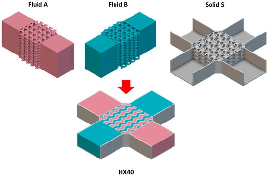
Figure 2.
HX40 heat exchanger. (red—hot fluid, blue—cold fluid, grey—solid).
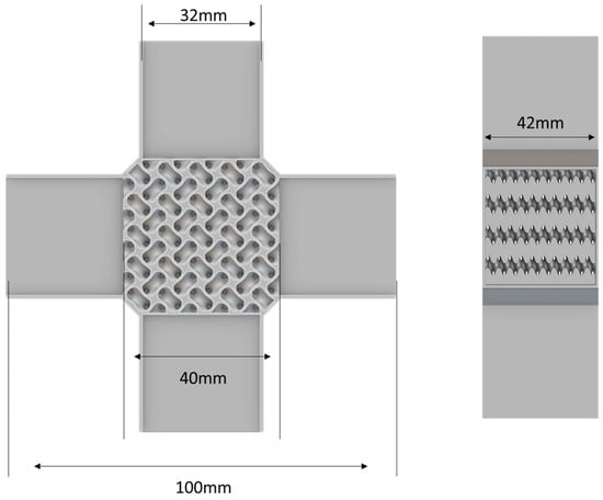
Figure 3.
Dimensions of the HX40. (grey—solid).
Due to the symmetry, Fluid A and Fluid B are identical and have the same performance. Both Fluid A and B contain liquid water. To minimize computation time, Fluid A in Figure 2 was modeled in ANSYS Fluent 2023 R1 to determine the performance for the HX40 with various TPMS lattices.
The K-Omega (k-ω) turbulence models are used in computational fluid dynamics (CFD) model to describe the behavior of turbulent flows. There are two transport equations in the model: one for the turbulent kinetic energy (k) and another for the specific dissipation rate (ω).
Key Equations:
Turbulent Kinetic Energy Equation:
: production of turbulent kinetic energy
: Empirical constant
: Turbulent viscosity
Specific Dissipation Rate () Equation:
: same as above
and : Empirical constant
The boundary conditions are shown in Figure 4. The inlet flow rate varies from 0.05 to 0.4 kg/s, and the inlet temperature is set at 288 K. The wall temperature of the lattice structure within Fluid A is kept constant at 343 K. Heat will be transferred from the wall to the fluid.
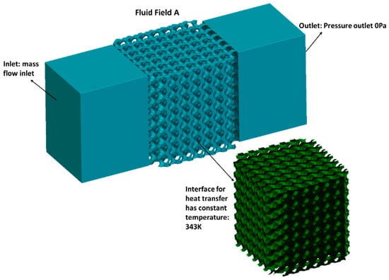
Figure 4.
Boundary conditions of the CFD model.
Figure 5 presents the 3D and 2D qualitative results of the flow field in volume A, providing valuable insights into the flow characteristics.

Figure 5.
Temperature field and velocity field in the HX40.
2.1. TPMS Type Comparison
In Figure 6, three representative TPMS lattices were used in the simulation to examine how different lattice types affect the efficiency and pressure drop of the HX40.
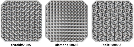
Figure 6.
Different types of TPMS lattice.
The Gyroid, Diamond, and SplitP lattices have different surface-to-volume ratios at the same lattice size. By varying the lattice size, the three TPMS structures achieve nearly the same surface area for heat transfer within the same volume which are shown in Table 1. The inlet, outlet, and thermal boundary conditions are consistent across all cases. The overall heat transfer coefficient and pressure drop are compared.

Table 1.
Parameters for different lattice in HX40.
The relationship of the flow rate, pressure drop and overall heat transfer coefficient (Uc × A) in different lattice are shown in Figure 7. Uc was average heat transfer coefficient and A is the surface area of the interface in the HX for heat transfer. The pressure drop has quadratic relationship with the flow rate. And the overall heat transfer coefficient (Uc × A) increases with the flow rate for all the lattices. In Figure 7, the overall heat transfer coefficient with the SplitP is about 6~8% higher than the Gyroid lattice. The pressure drop of the SplitP is 3~7% higher than the Gyroid lattice. Considering both the overall heat transfer coefficient and pressure drop, the SplitP and Gyroid show similar performances.
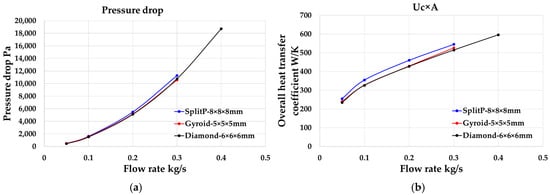
Figure 7.
(a) Pressure drop for different lattice; (b) Overall heat transfer coefficient for different lattice.
As shown in Figure 8, the heat transfer power of HX40 increase rapidly with the pump power of the flow under flow rate 0.1 kg/s. To save energy, it is efficient to make the HX40 works near 0.1 kg/s. The Reynolds number near this flow rate is within 300~800. The average velocity in the lattice is about 0.3 m/s.
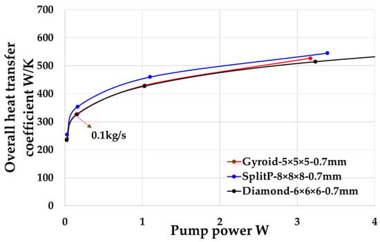
Figure 8.
Pumping power (Pe) for fluid flow and overall heat transfer coefficient for different lattice type.
In Figure 9, SplitP lattice with 8 × 8 × 8 mm has higher Nusselt number (Nu) at the same Reynolds number and Gyroid lattice has lower friction factor.
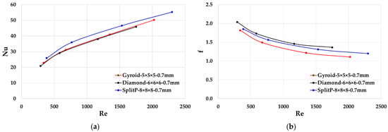
Figure 9.
(a) Nusselt number Nu; (b) Friction factor f for lattices with different types.
In Table 2, at the same flow rate of 0.1 kg/s, the three types of TPMS lattices have nearly identical heat transfer efficiency.
Table 2.
Performance comparison of three lattice at 0.1 kg/s.
2.2. Lattice Size Impact
To study the efficiency of the Gyroid lattice with different sizes, the lattice size was changed between 5 mm, 7 mm, and 10 mm.
As the lattice size decreased from 10 mm to 5 mm in Figure 10, the overall heat transfer coefficient Uc × A was doubled. The pressure drop increased by four times as the lattice size decreased from 10 mm to 5 mm.
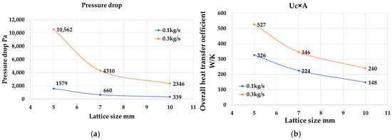
Figure 10.
(a) Pressure drop; (b) overall heat transfer coefficient of HX40 for various lattice types at different flow rates.
As shown in Figure 11, when the lattice size was decreased from 10 mm to 5 mm, Nu and f will be reduced. For all the lattice, the friction factor will change slowly at higher Re.
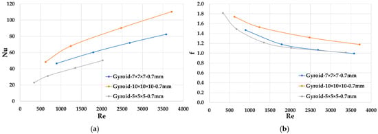
Figure 11.
(a) Nusselt number Nu; (b) Friction factor f for lattices with different size.
As illustrated in Figure 12, at the same pump power, the heat exchanger with a smaller lattice size is capable of transferring more heat power.
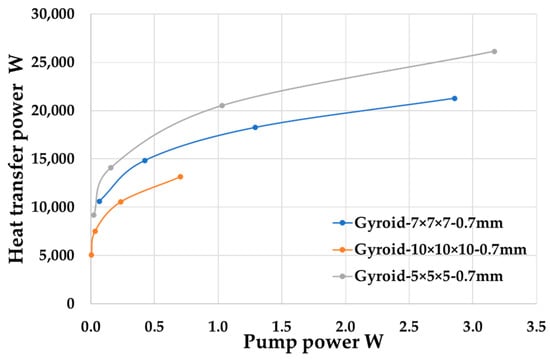
Figure 12.
Pump power for the fluid flow at different lattice size.
2.3. Wall Thickness Impact
Wall thickness has important effects on the heat transfer efficiency of HX40 with different lattice size. Table 3 shows the simulation results for different wall thickness in the Gyroid lattice with different size at flow rate 0.1 kg/s.
Table 3.
Effect of the wall thickness on the HX40.
As shown in Figure 13, when the lattice size is 5 × 5 × 5 mm, the Nusselt number (Nu) increases significantly at the same Reynolds number (Re) as the wall thickness decreases. When the lattice size 10 × 10 × 10 mm, the Nu is not very sensitive for the wall thickness. As shown in Figure 13c, the Nu of the Gyroid (10 × 10 × 10-1.05 mm) is significantly low. This is mainly caused by the reduction of the void volume which was reduced by 21.5%. And the hydraulic diameter is also reduced by 20%. The 1.05 mm thick wall occupied much volume and make the volume for the fluid much smaller. The hydraulic diameter is much smaller than that with 0.35 mm wall thickness.
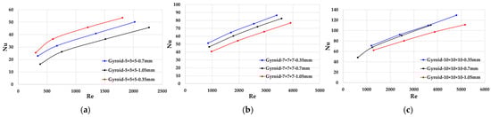
Figure 13.
(a) Nu and Re for lattice size: 5 × 5 × 5 mm; (b) Nu and Re for lattice size: 7 × 7 × 7 mm; (c) Nu and Re for lattice size: 10 × 10 × 10 mm.
As illustrated in Figure 14, the pressure drop of HX40 at 0.1 kg/s is sensitive to wall thickness of the lattice with small size such as 5 × 5 × 5 mm. As for 10 × 10 × 10 mm lattice, the pressure drop doesn’t change much with the wall thickness.
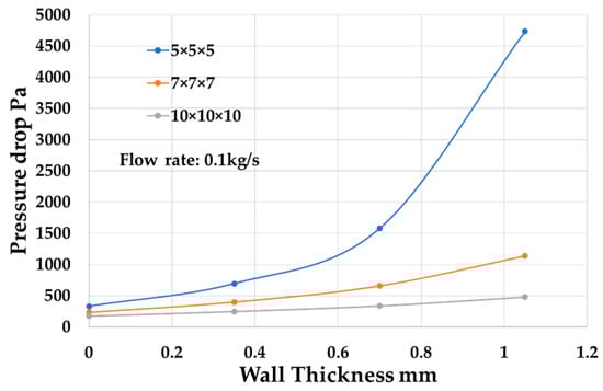
Figure 14.
Pressure drop with different wall thickness for different lattice size.
As shown in Figure 15, the overall heat transfer coefficient doesn’t change much with the lattice wall thickness. The wall thickness should be kept minimal to help reduce the pressure drop while maintaining the same overall heat transfer coefficient.
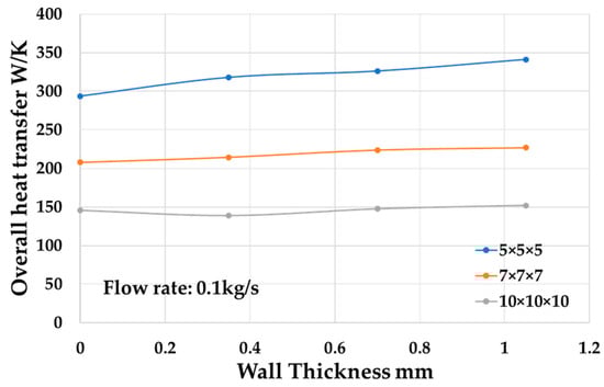
Figure 15.
Overall heat transfer coefficient with different wall thickness for different lattice size.
2.4. Aspect Ratio
The surface-to-volume ratio of the Gyroid lattice structure is determined by the unit lattice volume and wall thickness. When the wall thickness is 0.7 mm, the surface-to-volume ratio decreases with larger Gyroid unit lattice volume, as illustrated in Figure 16.
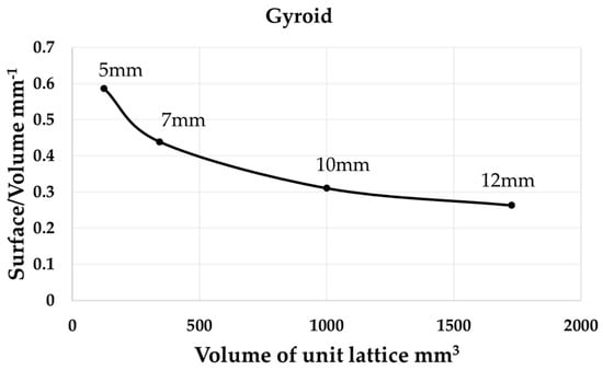
Figure 16.
Surface-area-to-volume ratio at different Gyroid lattice unit volume.
In Table 4, the volumes of the three types of Gyroid lattice unit is about 255 mm3. For the Gyroid lattice with the same unit lattice volume, the aspect ratio of the unit lattice is defined as the ratio of the longest edge and shortest edge. In case 1, the edge lengths in three directions are the same which is 6.3 mm and this lattice can be called cubic lattice. In case 2, the longest edge length is 10 mm and the rest two edge length is 5 mm. This lattice can be called thin lattice. In case 3, the shortest edge length is 4 mm and the other two edge length is 8 mm. The unit lattice can be called flat lattice. The three Gyroid unit lattices have identical volumes and nearly identical surface-to-volume ratios.
Table 4.
Gyroid unit lattices with different dimensions.
Using the lattices listed in Table 4, the volume and surface area of the HX40 shown in Figure 17 are kept consistent. The boundary conditions for the simulation are identical across all cases. The pressure drop and the overall heat transfer coefficients (Uc × A) are compared under the same flow rate 0.1 kg/s.
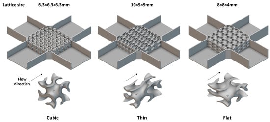
Figure 17.
HX40 infilled with lattice of varying sizes.
As shown in Table 5, the 10 × 5 × 5 mm lattice has nearly the same overall heat transfer coefficient with the 6.3 × 6.3 × 6.3 mm lattice. The pressure drop of 10 × 5 × 5 mm lattice is only 37% of the 6.3 × 6.3 × 6.3 mm lattice. However, for the second volume B of 10 × 5 × 5 mm lattice, the pressure drop is pretty high which is 2.16 times of the pressure drop of 6.3 × 6.3 × 6.3 mm lattice.
Table 5.
Simulation results for different lattice of varying sizes.
Compared with the 6.3 × 6.3 × 6.3 mm lattice, the flat lattice with 8 × 8 × 4 mm edge length was more efficient. The pressure drop was reduced by 35% and the overall heat transfer coefficient (Uc × A) was increased by 34%. Because of the symmetry of the flat lattice, the other fluid volume has similar performance compared to the first fluid volume.
As shown in Table 6, the flat lattice with 8 × 8 × 4 mm size has a higher Nu and a lower f value, which means the 8 × 8 × 4 mm lattice has better performance than the other two lattices with the same surface-to-volume ratio.
Table 6.
Re, Nu, and f of different lattice size at 0.1 kg/s.
2.5. TPMS Orientation Impact
The flow angle shown in Figure 18 is the angle between the flow direction and the lattice’s longest edge direction in the 10 × 5 × 5 mm gyroid lattice. The pressure drop can be influenced by the flow angle.
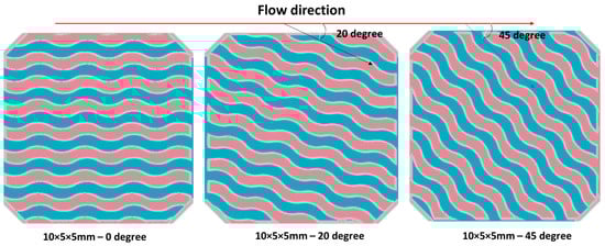
Figure 18.
The lattice structure with a different flow angle in HX40. (red—hot fluid, blue—cold fluid, grey—solid).
As shown in Table 7 and Figure 19, the angle between the flow direction and the lattice’s longer edge has an influence on the pressure drop. The big flow angle can increase the pressure drop significantly.
Table 7.
Simulation results for different flow angles.
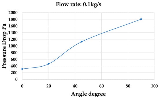
Figure 19.
The pressure drop at different flow angles.
2.6. Surface Area of Fluid at the Inlet and Outlet
The HX model, which was infilled with a Gyroid lattice in Figure 20, has the same volume for heat transfer as HX40. As shown in Figure 21, the surface area at the inlet and outlet of the two fluid volumes are different.
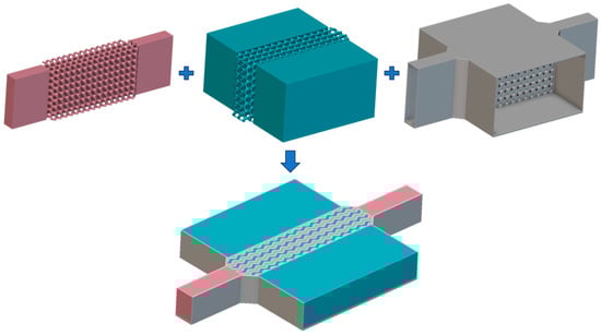
Figure 20.
HX model with different surface areas of fluid at the inlet and outlet. (red—hot fluid, blue—cold fluid, grey—solid).
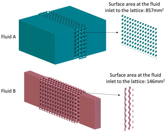
Figure 21.
HX with different surface areas at inlet and outlet. (red—hot fluid, blue—cold fluid).
The surface area at the inlet and outlet in fluid A is four times that in fluid B and is about two times of that in HX40. The flow rate in Table 8 is 0.05 kg/s.
Table 8.
Simulation results for different equivalent thicknesses at 0.05 kg/s.
The equivalent thickness of the Gyroid lattice structure in Table 8 is defined as the ratio of the volume to the average surface area at the inlet and outlet. When the equivalent thickness increased from 22 mm to 129.7 mm, the pressure drop increased by 65 times at the same flow rate while the overall heat transfer coefficient did not change much. The equivalent thickness can have a substantial impact on the pressure drop. Reducing the equivalent thickness of the lattice structure in the HX design can be an effective method for lowering the pressure drop in one fluid volume.
2.7. Sheet Gyroid Lattice Channel
The sheet Gyroid lattice can be used as the fluid channel in the HX design. The generation of the sheet Gyroid channel is shown in Figure 22. In Figure 23, the fluid B is a sheet Gyroid channel with an average width of 1.1 mm and fluid A is the Gyroid lattice channel. The lattice size is 10 × 10 × 10 mm.
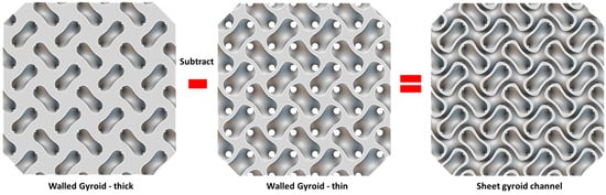
Figure 22.
Generation of the sheet Gyroid channel.
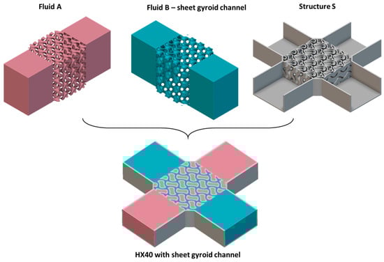
Figure 23.
HX40 with a sheet Gyroid lattice channel. (red—hot fluid, blue—cold fluid, grey—solid).
As shown in Table 9, the surface area of fluid B with sheet Gyroid channel is 50% bigger than that in fluid A.
Table 9.
Design parameters for HX with a sheet Gyroid channel.
In Table 10, the sheet Gyroid channel exhibits a much lower pressure drop at the same flow rate compared to the other fluid volume. However, the Uc × A remains nearly identical for both volumes at the same flow rate. The volume of the sheet Gyroid channel can be reduced to increase the volume of the other fluid. This adjustment can help balance the pressure drops between the two fluid volumes.
Table 10.
Simulation results for HX with sheet Gyroid channel.
3. Test on Various HXs
3.1. Design of Three HXs
As shown in Figure 24 and Figure 25, three HX samples that have the same dimensions were printed by the AM machine. The HX cores that are infilled with TPMS lattice in the Sample #1 and Sample #2 are the same.
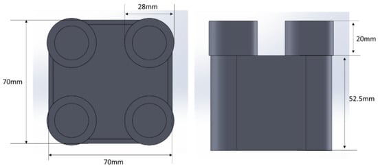
Figure 24.
Dimensions of the three HXs.
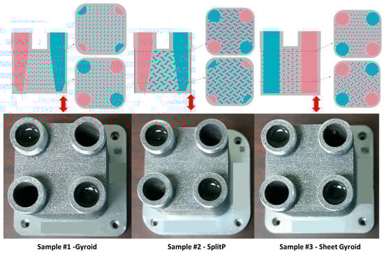
Figure 25.
Three HX samples for testing. (red—hot fluid, blue—cold fluid, grey—solid).
The design parameters of the three samples are listed in Table 11. The material of the HX is Aluminum. The lattice type and lattice dimension for Sample #1 and Sample #2 are different. The wall thickness of the lattice structure is adjusted to ensure that the fluid volume matches the test volume. For Sample #1 and Sample #2, the equivalent wall thicknesses are 1.22 mm and 0.9 mm, respectively. Sample #1 has a smaller fluid volume compared to Sample #2 and both samples have similar surface areas in their lattice structures. Additionally, the average channel width in Sample #1 is narrower than that in Sample #2.
Table 11.
Design parameters of three HX samples.
3.2. Test Results of Three HXs
Schematic of testing setup of heat exchanger was shown in Figure 26. There are two water loops in the test rig. The flow meter, pressure transducer, and temperature sensors are used to test the flow rate, pressure drop, and the temperature at the inlet and outlet. The experimental tests of the three samples are in accordance with ANSI/AHRI Standard 400 (I-P) [17]. The data are valid only if the heat balance is within ±5%. The error in the measured heat capacity due to sensor inaccuracies is within ±1.2%, which is relatively low.
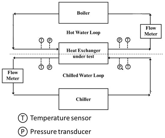
Figure 26.
Schematic of testing setup.
As shown in Table 12, for Sample #1 and Sample #2, the hot fluid volume and cold fluid volume are identical due to the symmetry and have the same pressure drop. For Sample #3, the cold fluid volume and hot fluid volume have different pressure drops.
Table 12.
Test results of three samples.
3.3. Simulation Results of Three HXs
As shown in Figure 27, the heat transfer rate in the heat exchanger is:
where and are the heat transfer coefficients for hot and cold fluids, respectively, and and are the heat transfer surface areas for the hot and cold fluids, respectively, and is the wall thermal resistance. is the log mean temperature difference [18].
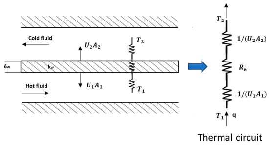
Figure 27.
Thermal resistance for a heat exchanger.
The wall thermal resistance is
where is the thickness of the wall, is the thermal conductivity of the wall and is the heat transfer area of the wall, which is the same as or in this case.
The heat exchanger overall heat transfer coefficient
As shown in Table 13, for Sample #1 and Sample #2, one fluid volume was calculated as the two volumes are symmetrical. The flow rate is equal to the test flow rate. The inlet temperature of the water is 291 K and the wall temperature of the lattice structure is constant at 349 K. The pressure drop and the overall heat transfer coefficient of the single volume () are calculated and the other volume has the same results. The overall heat transfer coefficient of the whole heat exchanger are calculated according to the Equation (9). For Sample #3, the two fluid volumes are different and both are modeled to calculate the pressure drop and overall heat transfer coefficient.
Table 13.
Simulation results of three samples.
3.4. Comparison of Simulation and Test Results
The pressure drop is proportional to the square of the flow rate in the Sample #1 and Sample #2. And the Uc × A is proportional to the square root of the flow rate.
The sheet Gyroid channel has very low pressure drop and the other fluid volume has high pressure drop.
According to Figure 28, Figure 29, Figure 30 and Figure 31, the numerical simulation can predict the performance trends of the heat exchanger at different flow rate. However, both the pressure drop and Uc × A calculated by CFD model are about 40% lower than the test results. The high surface roughness of the lattice structure could be the possible reason for this difference.
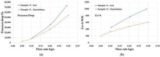
Figure 28.
Simulation and test results comparison of Sample #1 (a) Pressure drop; (b) Uc × A.
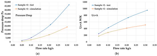
Figure 29.
Simulation and test results comparison of Sample #2 (a) Pressure drop; (b) Uc × A.

Figure 30.
Simulation and test results comparison of Sample #3 (a) Pressure drop of gyroid channel; (b) Pressure drop of sheet gyroid channel.
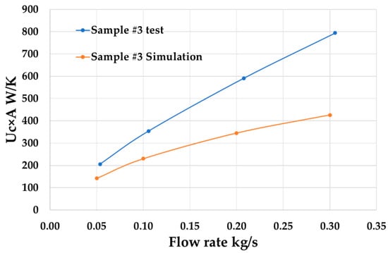
Figure 31.
Simulation and test results comparison of Sample #3—Uc × A.
As shown in Figure 32, the Gyroid lattice surfaces printed by AM machines often have many small particles adhering to them, resulting in higher surface roughness. These particles can increase the total surface area of the lattice and may enhance surface turbulence, potentially improving heat transfer efficiency. However, the presence of the small particles also reduce the fluid volume within the lattice and heighten turbulence, which could significantly raise the pressure drop across the heat exchanger. The simulation model needs to be optimized to account for the impact of the small particles on the surface.

Figure 32.
High roughness surface of the Gyroid lattice printed by AM machines.
In Figure 33, Samples #2 and #3 exhibit similar pressure drops when Uc × A equals 600 W/K, which is significantly lower than that of Sample #1. Sample #1 has a bigger equivalent wall thickness which causes a higher pressure drop.
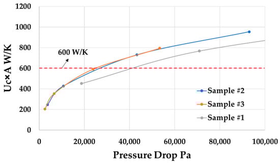
Figure 33.
Performance comparison of the three samples.
4. Conclusions
The paper presents a detailed investigation on the TPMS design variables to optimize the TPMS-HX. Some conclusions can be made as follows:
- The Gyroid, Diamond, and SplitP lattices show similar performances when the surface-to-volume ratio is kept the same.
- It is efficient to make the HX infilled with Gyroid lattice works at the point where the Re is about 300~800 and the average velocity in the lattice structure is about 0.3 m/s.
- The thin wall thickness of the lattice structure can reduce the pressure drop of the HX and keep the overall heat transfer coefficient the same.
- The flat lattice can reduce the pressure drop of HX compared with the cubic lattice with the same lattice unit volume.
- The bigger angle between the flow direction and the long lattice edge can increase the pressure drop.
- Reducing the equivalent thickness of the lattice structure is an effective method for decreasing the pressure drop.
- The sheet Gyroid channel has a much lower pressure drop compared with the other fluid volumes.
- The simulation predicted a lower pressure drop and overall heat transfer coefficient by about 40% compared to the test results. The high surface roughness of the lattice structure may be the possible reason for the difference; however, more investigation is needed to confirm.
Author Contributions
Conceptualization, J.L.; Methodology, J.L. and S.B.; Software, D.C.; Validation, J.L. and D.C.; Investigation K.O., W.P. and T.-L.M.; Writing—original draft, D.C. and J.L.; Writing—review and editing, J.L. and S.B.; Supervision, J.L.; Project administration, S.B. All authors have read and agreed to the published version of the manuscript.
Funding
This research received external funding from DoE under SBIR contract DE-SC0025372.
Data Availability Statement
The raw data supporting the conclusions of this article will be made available by the authors on request due to privacy.
Conflicts of Interest
Authors were employed by the company PolarOnyx, Inc.
References
- Balaji, C.; Srinivasan, B.; Gedupudi, S. (Eds.) Chapter 7—heat exchangers. In Heat Transfer Engineering; Academic Press: Cambridge, MA, USA, 2021; pp. 199–231. [Google Scholar]
- William, M.; Muley, A.; Bolla, J.; Strumpf, H. Advanced Heat Exchanger Technology for Aerospace Applications; SAE International: Warrendale, PA, USA, 2008. [Google Scholar]
- Jung, Y.; Torquato, S. Fluid permeabilities of triply periodic minimal surfaces. Phys. Rev. E Stat. Nonlinear Soft Matter Phys. 2005, 72, 056319. [Google Scholar] [CrossRef] [PubMed]
- Li, W.; Yu, G.; Yu, Z. Bioinspired heat exchangers based on triply periodic minimal surfaces for supercritical CO2 cycles. Appl. Therm. Eng. 2020, 179, 115686. [Google Scholar] [CrossRef]
- Passos, A.G.P. Laminar Flow and Heat Transfer in Triply Periodic Minimal Surfaces; Lund University: Lund, Sweden, 2020. [Google Scholar]
- Omri, M.; Smaoui, H.; Frechette, L.; Kolsi, L. A new microchannel heat exchanger configuration using CNT-nanofluid and allowing uniform temperature on the active wall. Case Stud. Therm. Eng. 2022, 32, 101866. [Google Scholar] [CrossRef]
- Ali, M.R.; Al-Khaled, K.; Hussain, M.; Labidi, T.; Khan, S.U.; Kolsi, L.; Sadat, R. Effect of design parameters on passive control of heat transfer enhancement phenomenon in heat exchangers—A brief review. Case Stud. Therm. Eng. 2023, 43, 102674. [Google Scholar] [CrossRef]
- Liu, J.; Cheng, D.; Oo, K.; McCrimmon, T.-L.; Bai, S. Design and Additive Manufacturing of TPMS Heat Exchanger. Appl. Sci. 2024, 14, 3970. [Google Scholar] [CrossRef]
- Al-Ketan, O.; Ali, M.; Khalil, M.; Rowshan, R.; Khan, K.A.; Al-Rub, R.K.A. Forced Convection Computational Fluid Dynamics Analysis of Architected and Three-Dimensional Printable Heat Sinks Based on Triply Periodic Minimal Surfaces. J. Therm. Sci. Eng. Appl. 2021, 13, 021010. [Google Scholar] [CrossRef]
- Iyer, J.; Moore, T.; Nguyen, D.; Roy, P.; Stolaroff, J. Heat transfer and pressure drop characteristics of heat exchangers based on triply periodic minimal and periodic nodal surfaces. Appl. Therm. Eng. 2022, 209, 118192. [Google Scholar] [CrossRef]
- Cheng, Z.; Li, X.; Xu, R.; Jiang, P. Investigations on porous media customized by triply periodic minimal surface: Heat transfer correlations and strength performance. Int. Commun. Heat Mass Transf. 2021, 129, 105713. [Google Scholar] [CrossRef]
- Cheng, Z.; Xu, R.; Jiang, P.X. Morphology, flow and heat transfer in triply periodic minimal surface based porous structures. Int. J. Heat Mass Transf. 2021, 170, 120902. [Google Scholar] [CrossRef]
- Reynolds, B.W. Simulation of Flow and Heat Transfer in 3D Printable Triply Periodic Minimal Surface Heat Exchangers; University of Canterbury: Christchurch, New Zealand, 2020. [Google Scholar]
- Zimmer, A.; PachecoAraújo, J.D.; Andreassen, K.A.; Grande, C.A. Effect of Manufacturing Techniques in Pressure Drop on Triple Periodical Minimal Surface Packings. Chem. Ing. Tech. 2021, 93, 967–973. [Google Scholar] [CrossRef]
- Attarzadeh, R.; Attarzadeh-Niaki, S.H.; Duwig, C. Multi-objective optimization of TPMS-based heat exchangers for low-temperature waste heat recovery. Appl. Therm. Eng. 2022, 212, 118448. [Google Scholar] [CrossRef]
- Attarzadeh, R.; Rovira, M.; Duwig, C. Design analysis of the “Schwartz D” based heat exchanger: A numerical study. Int. J. Heat Mass Transf. 2021, 177, 121415. [Google Scholar] [CrossRef]
- ANSI/AHRI Standard 400 (I-P); Performance Rating of Liquid to Liquid Heat Exchangers. Air-Conditioning, Heating, and Refrigeration Institute: Arlington, VA, USA, 2015.
- Lee, H. Thermal Design: Heat Sinks, Thermoelectrics, Heat Pipes, Compact Heat Exchangers, and Solar Cells; John Wiley & Sons: Hoboken, NJ, USA, 2010. [Google Scholar]
Disclaimer/Publisher’s Note: The statements, opinions and data contained in all publications are solely those of the individual author(s) and contributor(s) and not of MDPI and/or the editor(s). MDPI and/or the editor(s) disclaim responsibility for any injury to people or property resulting from any ideas, methods, instructions or products referred to in the content. |
© 2024 by the authors. Licensee MDPI, Basel, Switzerland. This article is an open access article distributed under the terms and conditions of the Creative Commons Attribution (CC BY) license (https://creativecommons.org/licenses/by/4.0/).