Abstract
Viscosity-reducer flooding is an effective method to improve oil recovery after the water flooding of heavy oil, and water-in-oil emulsion (W/O emulsion) is easily formed during this process. W/O emulsion has a strong ability to improve mobility ratio and block off high permeability layers, which can effectively improve sweep coefficient and enhance oil recovery. The microscopic visual glass model is mainly used to study the microscopic oil displacement mechanism of dilute oil; however, there are few studies on the emulsification mechanism and influencing factors of heavy oil. The purpose of this paper is to study the mechanism of heavy oil emulsification caused by viscosity reducer at the microscopic level, and the effect of emulsification on heavy oil recovery. The visible physical experiments with the glass microscopic models with different permeability and pore sizes were carried out to study the mechanism and main controlling factors of emulsification and the oil displacement effect of viscosity reducer. On this basis, the software was used to calculate the oil recovery in different areas of the model in different flooding stages, which provides a more intuitive understanding of the oil displacement effect of viscosity reducer. The results showed that there are mainly three types of emulsifications between pores: pore throat-breaking emulsification, blind-end emulsification, and pore channel extrusion emulsification. Hence, the mechanism of the three types of emulsifications and the relationship between droplet size with shear stress have been explored. The shear stress increased with the increase of the shear rate, and the oil droplet size in the model decreased with the increase of the shear. The blocking mechanism of pore throat and the shearing action of viscosity-reducer solution are the main mechanisms of viscous oil emulsification between pores. Generally, the particle size of the emulsified oil droplets formed by the blocking action is large, and it is easy to form pore throat emulsion. The particle size of emulsified oil droplets formed by shearing of viscosity-reducer solution is small. When the pore diameter is smaller than the particle size of oil droplets, the mobility of oil droplets between pores is poor, which means the oil droplets easily accumulate at the blind end to form residual oil. From the results of viscosity-reducer flooding experiments, the heavy oil recovery in each area of the model has been significantly improved after viscosity-reducer flooding compared with water flooding, with the recovery factor in the edge area of the model improving by up to 24.22%. The viscosity-reducer solution has a significant displacement effect on the residual oil in the edge area of the model.
1. Introduction
Heavy oil is an important oil resource in the world, and water flooding is a common and economical way to develop heavy oil reservoirs [1]. However, because the viscosity of heavy oil is much greater than water, the viscous fingering phenomenon is serious in waterflood. As a result, the sweep efficiency and oil recovery of waterflood in heavy oil reservoirs are low, and it is easy to produce self-emulsification in the process of water flooding.
An emulsion is a multiphase dispersion system formed by one liquid uniformly dispersed in another immiscible liquid. There are three different kinds of common emulsions; the first is oil-in-water (O/W) emulsion, the second is water-in-oil (W/O) emulsion, and the third is complex emulsions such as water-in-oil-in-water (W/O/W) [2]. A total of 95% of heavy oil is produced in the form of emulsion [3]. Oil and water phases are subjected to various shearing actions in the process of waterflooding, which can make the active components (such as asphaltene, colloid, etc.) in heavy oil gradually adsorb on the oil-water interface, and emulsions are formed [4]. In the reservoir, W/O emulsion can increase the viscosity of the flooding phase and the Jamin effect in the narrow pore throat expand the sweep volume of the flooding phase [5,6]. Therefore, the emulsion of heavy oil in the process of waterflood can effectively improve oil recovery.
The flow of emulsion in porous media can also be regarded as the deep filtration of emulsion droplets of different sizes in porous media [7]. Abdul’s research suggested that the ability of emulsion flooding to reduce the permeability of porous media depended on the ratio of emulsion droplet size to pore throat size; however, it had little correlation with crude oil viscosity. The mobility control effect of emulsion flooding on the reservoir in the process of oil recovery is one of the most recognized mechanisms for improving oil recovery [8]. Leopoldino et al. performed emulsion flooding experiments and obtained the result that emulsion flooding can be used in the stage of secondary oil recovery. By blocking the high permeability area, the emulsion increases the displacement pressure, which promoted the flow of the displacement fluid into the low permeability area, and then controlled the mobility so as to improve the oil displacement efficiency [9]. Chen et al. performed the physical simulation experiment of water flooding after emulsion flooding and obtained the same experimental results. The results showed that the decrease of porous media permeability was caused by emulsion drop blocking. It was also found that the effect of external emulsion injection to reduce permeability was better than that of in situ emulsion flooding, and emulsion should be used to block heterogeneous formation in the process of steam flooding to improve oil recovery [10]. Bryan et al. studied the formation mechanism of the emulsions, and the results showed that the oil–water emulsion appeared at the core outlet; however, the water-in-oil emulsion appeared at the core entrance [11]. Lifeng Chen et al. studied an alkaline/surfactant flooding system and obtained the result that an alkaline/surfactant system can form O/W emulsion with heavy oil at the displacement front and O/W emulsion in the swept region [12]. Haihua Pei conducted alkaline flooding microscopic experiments to investigate the emulsion mechanisms for heavy oil. The result showed that the alkaline solution promoted the formation of W/O emulsion, which reduced the mobility of the water phase and drove the water into the unswept region; thereby, the sweep efficiency of the alkaline solution was improved [13]. Zhengbin, Wu researched the emulsification process, and the result showed that the entrapment of oil-in-water emulsions played an important role in sweep efficiency improvement, and the addition of viscosity reducer improves the steam absorption profile and the oil–steam ratio could be improved after viscosity-reducer solution flooding in a heterogeneous reservoir [14].
The microscopic visual glass model is mainly used to study the microscopic oil displacement mechanism of dilute oil; however, there are few studies on the emulsification mechanism and influencing factors of heavy oil. Most studies were mainly macro-experiments, and there is a lack of microscopic visualization experimental study on heavy oil emulsification. As a result, the mechanism of heavy oil emulsification and the influencing factors of emulsification distribution in the process of viscosity-reducer flooding are not clearly understood. In this paper, glass microscopic models with different permeability and pore sizes were made. The physical experiments were carried out to study the emulsification mechanism and emulsification type between pores during viscosity-reducer flooding. On this basis, the influence of pore size and shear rate on the dispersion of heavy oil emulsions was also investigated. The software was used to calculate the oil recovery in different areas of the model in different flooding stages, which provides a more intuitive understanding of the oil displacement effect of viscosity reducer.
2. The Microscopic Visual Glass Model Experiments for Oil Heavy Emulsification
2.1. Materials
The pore distribution was obtained by processing the cast slice of the real formation core. The micro-etching models with different permeability were made according to the pore distribution, as shown in Figure 1. The parameters of the model are shown in Table 1.
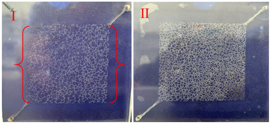
Figure 1.
Microscopic glass models with different pore throat sizes. (I): high porosity; (II): low porosity.

Table 1.
The parameters of glass micromodels.
The main experimental materials were heavy oil samples and formation water, which were provided by Jimusar Oilfield, Xinjiang, China. Table 2 lists the properties and composition of heavy oil samples. Table 3 lists the formation of water which was analyzed by ion chromatography. The viscosity reducer was AVS, and the viscosity reducer concentration was 0.09 wt. The heavy oil emulsion solution contained 50% water. The elastic modulus of the oil–water interface is basically stable between 8 × 10⁻⁶ and 9 × 10⁻⁶ Pa, while the particle size of emulsified oil droplets is in the range of 14–15 μm.
Table 2.
Properties and composition of heavy oil.
Table 3.
Ion composition of formation water.
The ratio of oil to water is 3:7, the temperature is 50 °C, and the viscosity of crude oil is 1231 mPa·s. The evaluation results of viscosity reduction are shown in Table 4. The viscosity reducer AVC (Octadecyl acrylate-styrene-vinyl acetate copolymer) is manufactured by Jingzhou Tianhe Technology Co., Ltd.
Table 4.
The evaluation results of viscosity reduction.
2.2. Experimental Apparatus
Figure 2 shows the microscopic visual glass model flooding experiment apparatus. It consists of three parts as follows:
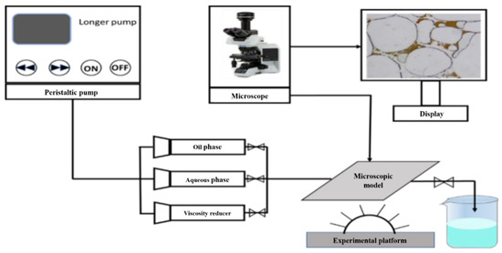
Figure 2.
Experimental device of microscopic visual glass model flooding.
- (1)
- Injection system. The system consists of three piston containers and a peristaltic pump, containing heavy oil samples, formation water, and viscosity reducer AVS, respectively.
- (2)
- (3)
- Microscopic visual flooding system. The system consists of an optical microscope and CCD camera for data acquisition, and Zeiss Axiovert software for image processing, which can achieve the function of fluid-flow image acquisition in the microflow channel.
2.3. Experimental Procedures
The main procedures were as follows:
- (1)
- The experimental equipment was connected according to Figure 2. The microscopic glass pore model was vacuumed first, and formation water was injected to make it full of the model; 0.729~1.215 mL formation water was injected into the models. The injection rate was 0.1 mL/min.
- (2)
- The heavy oil was injected into the model at a uniform rate to make the model saturated with the oil; 0.510~0.850 mL heavy oil was injected into the models. The injection rate was 0.02 mL/min.
- (3)
- Flooding fluid was injected (water or viscosity-reducer solution) at the same and constant speed for continuous flooding for 10 min. The injection rate was 0.12 mL/min.
- (4)
- The software was first calibrated, and then the data were continuously collected and recorded in order to observe the distribution of residual oil in the flooding processes. The dynamic images were taken from the flooding processes by the image analysis software.
- (5)
- The computer image-processing software was used to analyze the distribution of residual oil in the images of each stage to obtain the recovery factor in the flooding process.
- (6)
- After the experiment, the microscopic glass pore model was cleaned with petroleum ether and ethanol.
- (7)
- The experimental conditions were changed, then steps 1–6 were repeated again.
3. Results and Discussion
3.1. The Mechanism Analysis of Heavy Oil Emulsification during Viscosity-Reducer Solution Flooding
The emulsification of heavy oil between pores was observed by microscopic models. Emulsion is the key mechanism for enhancing heavy oil recovery. Through emulsification, oil-in-water (O/W) emulsion with low viscosity can be formed, thus improving the fluidity of heavy oil.
Figure 3 displays the emulsified state of heavy oil in model holes (a1, a2, a3: emulsified state of heavy oil in water driving; b1, b2, b3: emulsified state of heavy oil in viscosity-reducer driving). Figure 3 shows, the distribution of residual oil between model pores and the change of heavy oil emulsification with flooding time when different flooding methods were used (water flooding or viscosity-reducer solution flooding). Compared with Figure 3(b1) and Figure 3(b2), when the flooding time was 5 s, the heavy oil was emulsified into small oil droplets in the viscosity-reducer flooding; however, no obvious emulsification could be found in the heavy oil–water flooding. When the flooding time was 10 s, there was a massive amount of residual oil between the pores in the water flooding, compared with viscosity-reducer flooding. Because the viscosity reducer is amphiphilic, oil-in-water (O/W) emulsion is easily formed between the pores in the model. Through further analysis during viscosity-reducer flooding, there are mainly the following three types of emulsifications between pores: throat-breaking emulsification, blind-end emulsification, and pore channel extrusion emulsification.
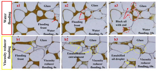
Figure 3.
The emulsified state of heavy oil in model holes during the flooding process. (a1) The emulsified state of heavy oil in model holes during water flooding at 0 s. (a2) The emulsified state of heavy oil in model holes during water flooding at 5 s. (a3) The emulsified state of heavy oil in model holes during water flooding at 10 s. (b1) The emulsified state of heavy oil in model holes during water flooding at 0 s. (b2) The emulsified state of heavy oil in model holes during water flooding at 5 s. (b3) The emulsified state of heavy oil in model holes during water flooding at 10 s.
3.1.1. Pore Throat-Breaking Emulsification
Figure 4 displays pore throat-breaking emulsification. Figure 5 shows the process of pore throat-breaking emulsification. As shown in Figure 4 and Figure 5, when the large oil drops flowed through small pores, large oil blocks were squeezed and deformed under the influence of stress in the process of viscosity-reducer flooding. When the deformation of oil drops reached a certain degree, large oil drops were broken to form small oil drops. In this process, the shear force of the pore throat is the main factor for emulsification.
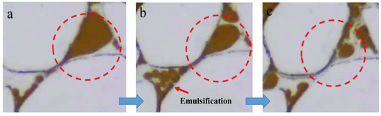
Figure 4.
Pore throat-breaking emulsification. (a) The beginning of the process of pore throat-breaking emulsification. (b) The middle of the process of pore throat-breaking emulsification. (c) The end of the process of pore throat-breaking emulsification.
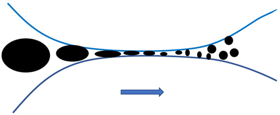
Figure 5.
The process of pore throat-breaking emulsification.
3.1.2. Blind-End Emulsification
Figure 6 displays blind-end emulsification. Figure 7 shows the process of blind-end emulsification. As shown in Figure 6 and Figure 7, the emulsification of the blind-end oil is mainly attributed to the viscoelastic properties of the viscosity-reducer solution. When the viscosity-reducer solution flowed through the blind end and contacted the oil drops, both the viscosity-reducer solution and the oil drops had a certain degree of deformation. However, because the heavy oil does not have the viscoelastic property, its deformation amplitude was less than that of the viscosity-reducer fluid and the heavy oil drops became small oil drops and then flowed out of the blind end under the constant extrusion of the viscosity-reducer fluid.
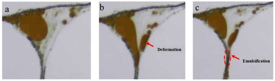
Figure 6.
Blind-end heavy oil emulsification. (a) The beginning of the process of blind-end heavy oil emulsification. (b) The middle of the process of blind-end heavy oil emulsification. (c) The end of the process of blind-end heavy oil emulsification.
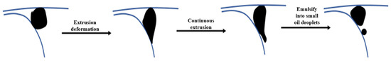
Figure 7.
The process of blind-end emulsification.
3.1.3. Channel-Extrusion Emulsification
Figure 8 displays channel-extrusion emulsification. Figure 8 shows the process of channel-extrusion emulsification. As shown in Figure 8 and Figure 9, when oil drops flowed through small channels, large oil drops were emulsified into the small oil drops. This process was the result of the joint effects of channel extrusion and viscosity reducer’s amphiphilic properties. First, when oil drops entered small channels, a large degree of deformation occurred. A deformation was the main factor for the large oil dropping to be emulsified. At the same time, due to the amphiphilic nature of viscosity-reducer solution, the oil–water interfacial tension was reduced, which made the oil droplets more easily emulsified into small oil droplets.
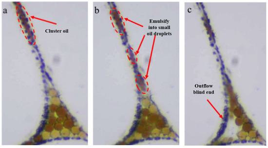
Figure 8.
Channel-extrusion emulsification. (a) The beginning of the process of channel-extrusion emulsification. (b) The middle of the process of channel-extrusion emulsification. (c) The end of the process of channel-extrusion emulsification.
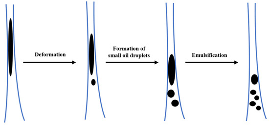
Figure 9.
The process of channel-extrusion emulsification.
3.2. Dispersing Emulsification in Viscosity-Reducer Flooding
In the late stage of high water saturation, controlling the fluidity of the injection fluid and expanding the swept volume are the keys to improving the recovery efficiency of heavy oil. The emulsion can control the mobility of water, depending on the Jamin effect, and play the role of improving the oil flooding efficiency, relying on its deformation microforce. Therefore, the formed emulsion is required to play the role of profile control. However, pore size and shear rate may lead to a dispersing emulsification. It is necessary to explore the effect of pore size and shear rate on the dispersing emulsification.
3.2.1. The Shear Rate Effect on Dispersing Emulsification
Due to the role of pore throat and pore channel, when the flooding phase percolates in the model, it has a certain shear effect on the flooding phase, and the shear rate (γ) is related to porosity (ϕ), permeability (k), and flooding speed (υ). Christopher and Middlemen’s formula was commonly used to calculate the shear rate in the oilfield. The formula is shown in Formula (1):
There is a relationship between shear rate (γ), shear stress (τ), and fluid viscosity, which is shown in Formula (1). After defining the shear rate and corresponding fluid viscosity value, the shear stress in the model can be calculated [15].
Wherein: γ—Shear rate (s−1); k—Water permeability (D); ϕ—Porosity; ν—Flooding linear velocity (μm/s).
There is a relationship between shear rate, shear stress, and fluid viscosity, which is shown in Formula (2). After defining the shear rate and corresponding fluid viscosity, the shear stress in the model could be calculated.
Wherein: γ—Shear rate (s−1); τ—Shear stress (Pa); η—Fluid viscosity (Pa·s).
In this experiment, the permeability was 0.07D, and the porosity was 0.15. Figure 10 shows the relationship between average particle size and shear stress of emulsified oil droplets with a shear rate. As shown in Figure 10, the shear stress increased with the expansion of the shear rate, and the oil droplet size in the model decreased with the increase of the shear. When the shear rate in the model was greater than 7 s−1, the emulsified oil droplets between model pores were smaller than the average diameter of the pore channel (30 μm). The pore throat emulsion was formed, which was conducive to enhancing heavy oil recovery. Considering all factors comprehensively, in the following research, the effect of pore throat channel size on the dispersing emulsification of heavy oil in the model was investigated at the shear rate of 7 s−1.
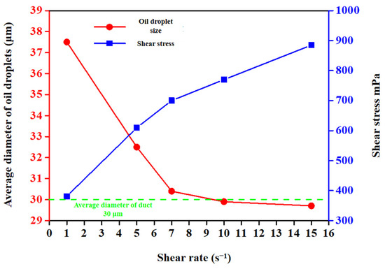
Figure 10.
The relationship between average particle size and shear stress with a shear rate.
3.2.2. Effect of Pore Size on Dispersing Emulsification
The microscopic models with different pore throat and pore channel sizes were selected. The shear rate in the models with different sizes was 7 s−1 and the shear stress was 700 mPa by controlling the flooding speed. The flooding velocity in different permeability and porosity models is shown in Table 4. Figure 11 shows the effect of different pore throat sizes on the emulsification and dispersion of heavy oil. Figure 12(a1–a3) shows the sticking phenomenon when the oil droplet passed through the pore throat with a diameter of 10 μm, and Figure 12(b1–b3) shows the phenomenon when the diameter of the oil droplet was 50 μm. As shown in Figure 11, when a large oil droplet with a diameter of 40 μm flowed through a small pore throat with a diameter of 10 μm, it broke down into small oil droplets, while when oil droplets of the same size flowed through a pore throat of 50 μm, the pore throat had no blocking effect on the oil droplet, and the oil droplets were coalesced to form oil droplets with a larger particle size. The blocking mechanism is an important mechanism for the generation of emulsion in rock porous media. During the process of residual oil passing through the pore throat, because the pressure is not enough to overcome the capillary resistance at the throat, the front end of the residual oil is cut off, while a large amount of residual oil at the rear edge is bound in the throat, and the separated residual oil quickly becomes spherical or ellipsoidal, forming a pore throat level emulsion that moves forward. Generally, the particle size of the emulsified oil droplets formed by the blocking action is large, and it is easy to form pore throat emulsion.
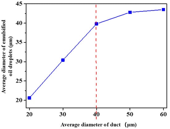
Figure 11.
The effect of different pore throat sizes on the emulsification and dispersion of heavy oil.
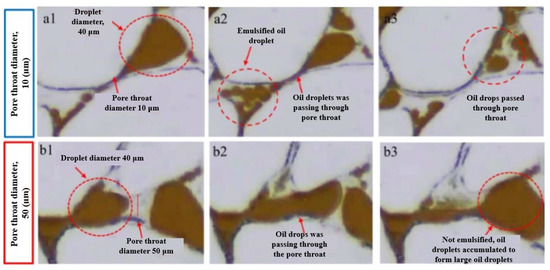
Figure 12.
The effect of different pore throat sizes (10 μm and 50 μm) on the emulsification and dispersion of heavy oil. (a1) The beginning of the process of emulsification and dispersion when the pore throat is 10 μm. (a2) The middle of the process of emulsification and dispersion when the pore throat is 10 μm. (a3) The end of the process of emulsification and dispersion when the pore throat is 10 μm. (b1) The beginning of the process of emulsification and dispersion when the pore throat is 50 μm. (b2) The middle of the process of emulsification and dispersion when the pore throat is 50 μm. (b3) The end of the process of emulsification and dispersion when the pore throat is 50 μm.
In addition to the blocking mechanism of pore throat, the shearing action of viscosity-reducer solution is also the main mechanism of viscous oil emulsification between pores. There is a velocity gradient between viscosity-reducer solution and residual oil. In porous media, the large residual oil film and the residual oil at the blind end are usually stripped away due to the shearing action of viscosity-reducer solution. When the viscosity-reducer solution flowed through the blind end, the blind-end oil is deformed due to the shear action of the viscosity-reducer solution. When the deformation reached a certain degree, small oil droplets flowed away with the viscosity-reducer solution. Generally, the particle size of emulsified oil droplets which is formed by shearing of viscosity-reducer solution is small.
Figure 13 shows the effect of different pore throat sizes on the emulsification and dispersion of heavy oil. Figure 13(a1–a3) shows the sticking phenomenon when the oil droplet passed through the pore throat with a diameter of 60 μm, and Figure 13(b1–b3) shows the phenomenon when the diameter of the oil droplet is 20 μm. The migration of heavy oil emulsion between pores is directly related to the recovery efficiency of heavy oil. When the pore diameter was larger than the size of emulsified oil droplets, oil droplets were able to pass through the pores smoothly and flowed out from the outlet end with the viscosity-reducer solution. When the pore diameter was smaller than the particle size of oil droplets, the mobility of oil droplets between pores was poor, and these oil droplets easily accumulated at the blind end to form residual oil. As shown in Figure 13, when the hole diameter was 60 μm, the maximum oil droplet diameter through the hole was 45 μm. The viscous oil emulsion flowing through could pass through the duct smoothly, and when the duct diameter was 20 μm, the oil droplets were larger than the diameter of the hole, and the oil droplets could pass through the hole smoothly only after being extruded and deformed. Due to the slow flow rate, the oil droplets gathered at the blind end and passed through to form the residual oil at the blind end with a larger particle size.
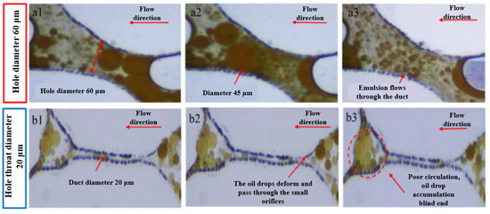
Figure 13.
The effect of different hole sizes (60 μm and 20 μm) on the emulsification and dispersion of heavy oil. (a1) The beginning of the process of emulsification and dispersion when the hole diameter is 60 μm. (a2) The middle of the process of emulsification and dispersion when the hole diameter is 60 μm. (a3) The end of the process of emulsification and dispersion when the hole diameter is 60 μm. (b1) The beginning of the process of emulsification and dispersion when the hole diameter is 20 μm. (b2) The middle of the process of emulsification and dispersion when the hole diameter is 20 μm. (b3) The end of the process of emulsification and dispersion when the hole diameter is 20 μm.
3.3. Heavy Oil Recovery in Viscosity-Reducer Flooding
The professional software “Photoshop” was used to process the image, and the heavy oil recovery factor was calculated according to Formula (3), through the change of remaining oil pixel points in the model before and after viscosity-reducer flooding:
In the actual flooding process, the heavy oil recovery in different areas of the microscopic model is different. Therefore, in order to analyze the effect of viscosity reducer as comprehensively as possible, the model was divided into four parts, according to the flow direction of the flooding phase for analysis: A—inlet end, B—middle of the model, C—outlet end, and D—edge area, as shown in Figure 14.
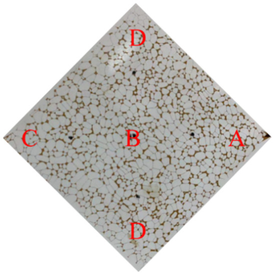
Figure 14.
Division of different regions of the microscopic model.
To further clarify the displacement effect of viscosity-reducer solution on heavy oil, the distribution of residual oil in different regions (inlet end, middle, outlet end, and edge) of the model was compared after water flooding and viscosity-reducer flooding, which is as shown in Figure 15, and the heavy oil recovery in each region after water flooding and viscosity-reducer flooding were calculated, according to Formula (3). The results are shown in Table 5.
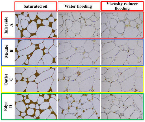
Figure 15.
Distribution characteristics of residual oil in different regions of model after flooding.
Table 5.
Heavy oil recovery in different areas of different flooding fluids.
It can be seen from Figure 15 that the displacement effect at the inlet end and the middle area was high, and there still was a lot of residual oil at the outlet end and the edge of the model after water flooding. The types of residual oil are mainly oil drop residual oil, blind-end residual oil, and cluster residual oil. There was no obvious residual oil distribution at the inlet, middle, and outlet of the model after viscosity-reducer flooding, and there still was a small amount of residual oil in the edge area, which was mainly at the blind end. The results of experiments show that viscosity-reducer solution can significantly increase the sweep area compared with water.
It can be seen from Table 5 that the heavy oil recovery at the inlet end was 82.56%, at the edge area it was 40.36%, and at the middle area and the outlet end, it was 48.12% and 40.36% after water flooding, respectively. This was because the flooding phase near the inlet end had a large flow rate and a large shear force on the residual oil when passing through the pores. The residual oil was easily emulsified and flowed well. When the flooding phase entered the edge area, the mobility decreased significantly and the shear force on the oil droplets decreased. Therefore, the ability of water to flood residual oil decreased. Compared with water flooding, the heavy oil recovery in each area of the model significantly improved after viscosity-reducer flooding, with the recovery factor in the edge area of the model improving by up to 24.22%. The results of experiments show that the viscosity-reducer solution has a significant displacement effect on the residual oil in the edge area of the model.
4. Conclusions
- (1)
- Compared with water flooding, the oil-in-water (O/W) emulsion formed easily between the pores of the model in viscosity-reducer flooding because viscosity reducer is amphiphilic. There are mainly the following three types of emulsifications between pores: pore throat-breaking emulsification, blind-end emulsification, and pore channel extrusion emulsification. The processes and mechanisms of the three types of emulsifications have been explored.
- (2)
- The shear stress increased with the expansion of the shear rate, and the oil droplet size in the model decreased with the increase of the shear. When the shear rate in the model was greater than 7 s−1, the emulsified oil droplets between model pores were smaller than the average diameter of the pore channel (30 μm).
- (3)
- The blocking mechanism of the pore throat and the shearing action of viscosity-reducer solution is the main mechanism of viscous oil emulsification between pores. Generally, the particle size of the emulsified oil droplets, which are formed by the blocking action is large, and it is easy to form a pore throat emulsion. The particle size of emulsified oil droplets, which are formed by shearing of viscosity-reducer solution is small. When the pore diameter is smaller than the particle size of oil droplets, the mobility of oil droplets between pores is poor, and they easily accumulate at the blind end to form residual oil.
- (4)
- Compared with water flooding, the heavy oil recovery in each area of the model significantly improved after viscosity-reducer flooding, with the recovery factor in the edge area of the model improving by up to 24.22%.
Author Contributions
Y.J. and B.W. designed and conducted the experiments, as well as writing the main manuscript text; C.W. and F.Z. conducted numerical simulation; Z.Q. and G.L. (Guoliang Liu) revised the main manuscript text; J.Z. and Y.Z. designed the experiment; G.L. (Guofeng Lian) prepared all of the Figures. As the corresponding author, P.L. made substantial contributions to the conception/design of the work and approved the final version to be published; And Y.J. agree to be accountable for all aspects of the work in ensuring that questions related to the accuracy or integrity of any part of the work are appropriately investigated. All authors have read and agreed to the published version of the manuscript.
Funding
This work was financially supported by the Scientific Research and Technology Development Project of China National Petroleum Corporation (2021DJ1406) and Fundamental Research Funds of China National Petroleum Corporation (2017D-5008-04).
Data Availability Statement
Not applicable.
Acknowledgments
The authors would like to thank the research team members for their contributions to this work.
Conflicts of Interest
The authors declare no conflict of interest. The funders had no role in the design of the study, in the collection, analyses, or interpretation of data, in the writing of the manuscript, or in the decision to publish the results.
References
- Li, J.N.; Liu, Q. On the Position of Heavy Oil in Energy in the 21st Century. Oil-Gas Field Surf. Eng. 2000, 19, 4–6. [Google Scholar]
- Wang, J.; Dong, M. Simulation of O/W Emulsion Flow in Alkaline/Surfactant Flood for Heavy Oil Recovery. J. Can. Pet. Technol. 2010, 49, 46–52. [Google Scholar] [CrossRef]
- Rashid, Z.; Wilfred, C.D.; Gnanasundaram, N.; Arunagiri, A.; Murugesan, T. A comprehensive review on the recent advances on the petroleum asphaltene aggregation. J. Pet. Sci. Eng. 2019, 176, 249–268. [Google Scholar] [CrossRef]
- Afra, S.; Nasr, H.A.; Socci, D.; Cui, Z. Green phenolic amphiphile as a viscosity modifier and asphaltenes dispersant for heavy and extra-heavy oil. Fuel 2018, 220, 481–489. [Google Scholar] [CrossRef]
- Daaou, M.; Larbi, A.; Martinez, B.; Rogalski, M. A comparative study of the chemical structure of asphaltenes from algerian petroleum collected at different stages of extraction and processing. J. Pet. Sci. Eng. 2016, 138, 50–56. [Google Scholar] [CrossRef]
- Umar, A.A.; Saaid, I.B.; Sulaimon, A.A.; Pilus, R.B.M. A review of petroleum emulsions and recent progress on water-in-heavy oil emulsions stabilized by natural surfactants and solids. J. Pet. Sci. Eng. 2018, 165, 673–690. [Google Scholar] [CrossRef]
- Xu, M.J.; Li, M.Y.; Peng, B.; Lin, M.Q.; Guo, J.X. Relationship between interfacial shear viscosity of resins and asphaltenes and emulsion stability in water-in-oil emulsions. Acta Pet. Sin. 2007, 3, 107–110. [Google Scholar]
- Abdul, H.J.; Ali, S.M.F. Combined Polymer and Emulsion Flooding Methods for Oil Reservoirs With a Water Leg. J. Can. Pet. Technol. 2003, 42, 35–40. [Google Scholar] [CrossRef]
- Leopoldino, R.; Carvalho, M.; Souza, A.; Hirasaki, G.J.; Miller, C.A. A Comparative Study of Emulsion Flooding and other IOR Methods for Heavy Oil Fields. Soc. Pet. Eng. 2012, 12, 105–117. [Google Scholar]
- Chen, L.; Zhang, G.; Ge, J.; Jiang, P.; Tang, J.; Liu, Y. Research of the heavy oil displacement mechanism by using alkaline/surfactant flooding system. Colloids Surf. A Physicochem. Eng. Asp. 2013, 434, 63–71. [Google Scholar] [CrossRef]
- Bryan, J.; Mai, A.; Kantzas, A. Processes responsible for heavy-oil recovery by alkali/surfactant flooding. J. Pet. Technol. 2009, 61, 52–54. [Google Scholar]
- Dong, M.; Ma, S.; Liu, Q. Enhanced heavy oil recovery through interfacial instability: A study of chemical flooding for brintnell heavy oil. Fuel 2009, 133, 454–460. [Google Scholar] [CrossRef]
- Pei, H.; Zhang, G.; Ge, J.; Jin, L.; Ma, C. Potential of alkaline flooding to enhance heavy oil recovery through water-in-oil emulsification. Fuel 2013, 121, 323–331. [Google Scholar] [CrossRef]
- Zhengbin, W.; Huiqing, L.; Xue, W.; Zhang, Z. Emulsification and improved oil recovery with viscosity reducer during steam injection process for heavy oil. J. Ind. Eng. Chem. 2018, 23, 1253–1257. [Google Scholar]
- Yang, F.; Li, C.X.; Lin, M.Z.; Guo, G. Effect of emulsification conditions on rheology of O/W heavy oil emulsion. J. Petrochem. Univ. 2009, 22, 51–54. [Google Scholar]
Disclaimer/Publisher’s Note: The statements, opinions and data contained in all publications are solely those of the individual author(s) and contributor(s) and not of MDPI and/or the editor(s). MDPI and/or the editor(s) disclaim responsibility for any injury to people or property resulting from any ideas, methods, instructions or products referred to in the content. |
© 2023 by the authors. Licensee MDPI, Basel, Switzerland. This article is an open access article distributed under the terms and conditions of the Creative Commons Attribution (CC BY) license (https://creativecommons.org/licenses/by/4.0/).